JP5146039B2 - Reinforcement structure of automotive front fender - Google Patents
Reinforcement structure of automotive front fender Download PDFInfo
- Publication number
- JP5146039B2 JP5146039B2 JP2008077238A JP2008077238A JP5146039B2 JP 5146039 B2 JP5146039 B2 JP 5146039B2 JP 2008077238 A JP2008077238 A JP 2008077238A JP 2008077238 A JP2008077238 A JP 2008077238A JP 5146039 B2 JP5146039 B2 JP 5146039B2
- Authority
- JP
- Japan
- Prior art keywords
- front fender
- edge
- fender
- reinforcing member
- vehicle
- Prior art date
- Legal status (The legal status is an assumption and is not a legal conclusion. Google has not performed a legal analysis and makes no representation as to the accuracy of the status listed.)
- Active
Links
- 230000002787 reinforcement Effects 0.000 title claims description 22
- 230000003014 reinforcing effect Effects 0.000 claims description 55
- 239000000853 adhesive Substances 0.000 claims description 18
- 230000001070 adhesive effect Effects 0.000 claims description 18
- 230000002093 peripheral effect Effects 0.000 claims description 16
- 230000008878 coupling Effects 0.000 description 4
- 238000010168 coupling process Methods 0.000 description 4
- 238000005859 coupling reaction Methods 0.000 description 4
- 238000003466 welding Methods 0.000 description 3
- 238000005187 foaming Methods 0.000 description 2
- 239000002184 metal Substances 0.000 description 2
- 229920001807 Urea-formaldehyde Polymers 0.000 description 1
- 238000005452 bending Methods 0.000 description 1
- 230000007423 decrease Effects 0.000 description 1
- 238000003795 desorption Methods 0.000 description 1
- 238000001035 drying Methods 0.000 description 1
- 230000000694 effects Effects 0.000 description 1
- 239000004088 foaming agent Substances 0.000 description 1
- 238000009434 installation Methods 0.000 description 1
- 239000000463 material Substances 0.000 description 1
- 238000007591 painting process Methods 0.000 description 1
- 239000005011 phenolic resin Substances 0.000 description 1
- 238000004080 punching Methods 0.000 description 1
Images


Landscapes
- Body Structure For Vehicles (AREA)
Description
本発明は自動車用フロントフェンダの張り剛性を強化する補強構造に関する。 The present invention relates to a reinforcing structure that reinforces the stiffness of an automobile front fender.
従来、図7に示すように、自動車の車体前部の側面を被覆するフロントフェンダ1は、外周縁に設けられた複数の結合部100,100,・・を車体側に脱着可能に結合して車体前部の側面を覆うように取付けられる。
一般に、図7に示したセミボンネットタイプのミニバンなどの車両では、フロントフェンダ1はその上下幅が乗用車のフロントフェンダのそれよりも広く、またその縦断面形状は、車外側へ膨出する湾曲形状の乗用車のものに比べ、決められた車体幅に対して車室幅を最大に設定するために、図8に示すようにほぼ垂直な平坦形状とされている。なお、図例のフロントフェンダ1はその上部、中間部および下部とで、若干傾斜を変えているものの全体的にほぼ垂直平面をなす。
Conventionally, as shown in FIG. 7, a
In general, in a vehicle such as a semi-bonnet type minivan shown in FIG. 7, the
ところで、車外側へ膨出する湾曲形状の縦断面を有する乗用車のフロントフェンダでは、車外側から人が接触してこれを押すように作用する外力に対して十分な張り剛性を発揮するが、ミニバンのフロントフェンダ1では縦断面が垂直平面なため、上記外力(図8の白矢印)に対して張り剛性が充分とは言えず、上記外力により車内側へ凹み、特に上下中間位置がベコベコするといった問題があった。
By the way, in the front fender of a passenger car having a curved longitudinal section that bulges to the outside of the vehicle, the minivan can exhibit sufficient tension rigidity against an external force acting so that a person contacts and pushes from the outside of the vehicle. In the
フェンダの補強構造としてはリヤフェンダの場合、下記特許文献1に記載されたように、車体の側部後方の骨格部材たるリヤピラーのピラーリィンフォースメントの車外面および上記リヤピラーから後方へ延びるベルトラインリィンフォースメントの車外面にリヤフェンダの車内面を固着してリヤフェンダを補強することが提案されている。
しかしながら、車体に脱着可能に設置されるフロントフェンダ1では、特許文献1の構造のように、車体の骨格部材に固着することができない。フロントフェンダ1の張り剛性を強化するためにフロントフェンダ1の板厚を厚くすると車体重量の増加やこれに伴うコストの増加、およびプレス成形されるフロントフェンダの生産性が低下する。
そこで本発明は、板厚を厚くすることなく、フロントフェンダの張り剛性を強化する補強構造を提供することを課題としてなされたものである。
However, the
Therefore, the present invention has been made to provide a reinforcing structure that reinforces the tension rigidity of the front fender without increasing the plate thickness.
本発明は、車体の前部側面を被覆し、外周縁を車体側に結合した自動車のフロントフェンダにおいて、フロントフェンダの車内面には、その上下中間位置に、上記車内面に沿うように前後方向に帯状に延びる補強部材を設け、該補強部材は、その前端部および後端部をそれぞれフロントフェンダの外周前縁および外周後縁に結合せしめるとともに、上記補強部材の前後中間部は、その上縁部および下縁部を前後方向に間隔を置いて複数個所で、かつ前後方向に上縁部と下縁部を交互位置でフロントフェンダの車内面に接着剤により接着せしめる(請求項1)。
フロントフェンダの車内面に沿って補強部材を設けたので、補強部材により車外側から作用する外力に対してフロントフェンダの張り剛性を強化することができる。またフロントフェンダの車内面を直接的に車体の骨格部材に取付けていないので、フロントフェンダの脱着性に影響はない。
The present invention is directed to a front fender of an automobile in which a front side surface of a vehicle body is covered and an outer peripheral edge is coupled to the vehicle body side. a reinforcing member that extends in a strip shape provided, reinforcing members, together with allowed to bind its front and rear ends of the outer peripheral front edge and the outer peripheral rear edge of each front fender, the intermediate portion before and after the reinforcing member, the upper edge The upper and lower edge portions are adhered to the vehicle inner surface of the front fender with an adhesive at a plurality of locations at intervals in the front-rear direction and at the upper and lower edge portions alternately in the front- rear direction .
Since the reinforcing member is provided along the vehicle inner surface of the front fender, the tension rigidity of the front fender can be strengthened against the external force acting from the outside of the vehicle by the reinforcing member. Since not attached to the body of the frame member directly the interior surface of the front fender, it affects the desorption of the front fender does not.
上記接着剤として発泡接着剤を用いる(請求項2)。
発泡接着剤を用いることで、補強部材とフェンダ内面との間の隙間で接着剤が容易に膨張して確実に両者を接着することができる。
A foamed adhesive is used as the adhesive.
By using the foamed adhesive, the adhesive easily expands in the gap between the reinforcing member and the inner surface of the fender, so that both can be securely bonded.
上記フロントフェンダの外周前縁には、車体の前面に設置されたヘッドランプの後縁に対応して後方へ凹状に切欠いたランプ対応部が形成され、かつ該ランプ対応部の周縁沿いには車内側に該周縁を補強するリィンフォースメントが設置され、上記補強部材はその前端を上記リィンフォースメントに結合し、後端をフロントフェンダの後縁に結合せしめるとともに、中間部をフロントフェンダの車内面に接着せしめる(請求項3)。
フロントフェンダの外周前縁に補強部材用の結合部を設けることなく、補強部材はその前端をフロントフェンダの外周前縁に設けられたリィンフォースメントに容易に結合できる。
The front fender has an outer peripheral front edge formed with a lamp-corresponding portion that is recessed backward corresponding to the rear edge of the headlamp installed on the front surface of the vehicle body. A reinforcement that reinforces the periphery is installed on the inner side, and the reinforcing member has a front end coupled to the reinforcement, a rear end coupled to a rear edge of the front fender, and an intermediate portion disposed on the inner surface of the front fender. (Claim 3).
The reinforcing member can be easily coupled to the reinforcement provided at the front outer periphery of the front fender without providing a connecting portion for the reinforcing member at the front outer periphery of the front fender.
上記補強部材は車外側に向けて開口する断面ハット形に形成し、上記上縁部および下縁部の前端を上記フロントフェンダの外周前縁または上記リィンフォースメントに結合し、上記補強部材の後端に形成した結合部をフロントフェンダの後縁に屈曲形成されて車内側へ張り出す後縁フランジに結合せしめる(請求項4)。
断面ハット形の補強部材は小型細幅のものでも充分に剛性があり、フロントフェンダの補強に好適である。
The reinforcing member is formed into cross-sectional hat shape opening toward the vehicle exterior side, the front end of the upper edge portion and lower edge portion bonded to the outer peripheral front edge or the reinforcement member of the front fender, after the reinforcing member The connecting portion formed at the end is bent at the rear edge of the front fender and is connected to the rear edge flange projecting toward the vehicle interior.
The cross-sectional hat-shaped reinforcing member is sufficiently rigid even if it has a small and narrow width, and is suitable for reinforcing the front fender.
上記補強部材は、複数の抜き穴を設けて軽量となす(請求項5)。
補強部材の軽量化が図れる。上記外力は人の手が押す程度の外力を想定しており補強部材の強度は充分である。
The reinforcing member is lightened by providing a plurality of punched holes.
The weight of the reinforcing member can be reduced. The external force is assumed to be an external force pressed by a human hand, and the strength of the reinforcing member is sufficient.
上記補強部材を、ほぼ垂直平面をなし、かつ車体に脱着可能に取付けられたフロントフェンダに取付ける(請求項6)。
垂直平面のフロントフェンダは張り剛性が不十分で、補強部材により好適に剛性強化できる。
The reinforcing member is attached to a front fender having a substantially vertical plane and detachably attached to the vehicle body.
The vertical plane front fender has insufficient tension rigidity and can be suitably reinforced by the reinforcing member.
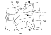
本発明をミニバン等の車両のフロントフェンダに適用した実施形態を説明する。フロントフェンダは左右対称な構造で一方の構造を説明する。図1に示すように、フロントフェンダ1は車体の前部側面を被覆する形状としてあり、その上下寸法は乗用車のフロントフェンダに比べて大きく設定してある。車体の前部外面をなすフロントフェンダ1の一般部10は、その縦断面形状がほぼ垂直な平面としてある。
An embodiment in which the present invention is applied to a front fender of a vehicle such as a minivan will be described. The front fender is a symmetrical structure, and one structure will be described. As shown in FIG. 1, the
フロントフェンダ1には、外周縁をなす外周前縁11に、前方に向けて開口する断面ほぼコ字形をなす切欠きを形成し、車両のヘッドランプユニット4の側面部を嵌合するようにランプ対応部11aが形成してある。ランプ対応部11aの奥縦縁には水平断面ほぼZ字状に屈曲形成してフロントフェンダ1の一般部10よりも車内側に変位せしめた結合フランジ111が形成してある(図2参照)。
また外周前縁11の下半部は車両のフロントバンパ5の側部に対応し、該下半部にはフロントバンパ5と結合する取付部100が設けてある。
The
The lower half portion of the outer peripheral
フロントフェンダ1の外周上縁12は、その前半部が車体のエンジンルームの開口側縁に沿って緩やかな前下がりの傾斜状をなし、フロントピラー6の下端を被覆する中間の突出部13より後方の後半部は車体のフィックスウィンドウ開口7の下縁に沿ってほぼ水平に形成してある。
外周上縁12の前半部および突出部13の下縁にはそれぞれ、車体のエプロンメンバ上縁およびフィックスウィンドウ開口7の周縁に結合する複数の取付部100,100,・・が設けてある
The front edge of the
The front half of the outer peripheral
車体のフロントドア開口8の前縁に沿うフロントフェンダ1の外周後縁14には車内へ屈曲形成した後縁フランジ141が設けてある(図3参照)。後縁フランジ141にはその上端および上下中間に、後縁フランジ141を車両のフロントドア開口8の前縁をなすフロントピラーの下半部へ結合する複数の取付部100,100が形成してある。
A
更にフロントフェンダ1には、車体のフロントホイールハウスをなすアーチ状の外周下縁15の前後中間位置および下端末に複数の取付部100,100,・・を有する。
Further, the
フロントフェンダ1の一般部10の車内面には上下中間位置に、これに沿って前後方向にほぼ水平に帯状に延び、外周前縁11の結合フランジ111および後縁14の後縁フランジ141間を架け渡すように補強部材2が設置してある。
The inner surface of the
図1ないし図3に示すように、補強部材2は金属板からなり、車内側に向けて開口する浅い断面ほぼハット形で、奥壁部20、上縁部21および下縁部22を備えている。補強部材2の前端部24は上縁部21および下縁部22の前端をそれぞれ、フロントフェンダ1の前縁フランジ111にその車内側から重ね合わせてスポット溶接SPして結合してある。なお、結合フランジ111と補強部材2の前端結合部はヘッドランプユニット4の側部後縁で覆い隠される。
As shown in FIG. 1 to FIG. 3, the reinforcing
補強部材2の後端部25には奥壁部20の端末からフロントフェンダ1の後縁フランジ141に対応して車内側へ屈曲形成した結合部251が形成してある。補強部材2の後端部25は結合部251をフロントフェンダ1の後縁フランジ141と前後方向に重ね合わせてスポット溶接SPにより結合してある。
The
更に、補強部材2はその上縁部21および下縁部22にそれぞれ、上下の幅を若干拡大した拡大部が前後に間隔を置いて複数形成してあり、これら拡大部を接着剤26によりフロントフェンダ1の車内面に接着してある。なお、上縁部21および下縁部22のフロントフェンダ1への接着部は前後方向に交互に設定してある。
Further, the reinforcing
接着剤26として、ユリア樹脂あるいはフェノール樹脂接着剤に特殊な発泡剤を添加し、熱により発泡硬化する発泡接着剤を用いる。補強部材2は前端24および後端25をフロントフェンダ1の前縁フランジ111および後縁フランジ141に溶接しておき、塗装工程の熱乾燥により、予め補強部材2の上縁部21および下縁部22に付着しておいた接着剤26を発泡硬化させて接着する。
As the
また補強部材1は、その奥壁部20に前後方向に間隔をおいて前後方向に長径の複数の抜き穴23が形成してあり、軽量化を図っている。
Further, the reinforcing
フロントフェンダ1は、上縁12、後縁14およびその端末の結合部100,100,・・を車体の骨格部材たるエプロンメンバ上縁、フロントピラー6の下半部およびロッカー9の前端にボルト締めまたはクランプ止めにより結合してある。また、前縁11下半部と下縁15の取付部100,100,・・をフロントバンパ5の側部およびホイールハウス内のフェンダライナーに締結してある。
In the
本実施形態によれば、フロントフェンダ1の上下中間位置に、前後端24,25をフェンダの前後の端縁111,141に溶接結合し、前後中間部をフェンダの車内面に接着(26,26,・・)した補強部材を設けたので、フロントフェンダ1の一般部10の張り剛性が強化され、人の手などが接触して車内側へ押されてもフロントフェンダ1は撓まずベコベコしない。
またフロントフェンダ1はその車内面および補強部材2を車両の骨格部材に結合していないので、フロントフェンダ1の脱着性能に支障はない。
According to the present embodiment, the front and
Moreover, since the
補強部材は比較的上下幅の細いものでよく、かつ複数の抜き穴26,26,・・を設けて軽量化してあるので、重量増も最小限で済む。またこのようにしても、補強部材2は上記人の手の接触などによる外力に対して充分に補強効果を発揮できる。または補強部材は必ずしも、図例の位置に限らず設置を変更することで、問題の起こりやすい部位を直接補強することができる。
The reinforcing member may have a relatively narrow vertical width and is lightened by providing a plurality of punched
また接着剤26に発泡接着剤を用いたので、接着剤26が膨張硬化することで、フロントフェンダ1の車内面と補強部材1の接着部とを車幅方向に隙間なく接着して確実にフロントフェンダ1の撓みを防止できる。
Further, since a foamed adhesive is used for the adhesive 26, the adhesive 26 expands and hardens so that the vehicle inner surface of the
次に、図5、図6に基いて本発明の他の実施形態を説明する。本実施形態の基本構造は、先の実施形態のそれとほぼ同じで、相違点を中心に説明する。図において、同一部材は同一符号で表し、これらの説明を省略する。
近時、自動車ではヘッドランプユニット4の側面部の意匠を後方へ拡張する傾向がある。この場合、フロントフェンダ1の前縁11には、前方に向けて開口し、上記ヘッドランプユニット4の側面部に対応して奥行寸法を大きく切欠いたランプ対応部11bが形成してある。
Next, another embodiment of the present invention will be described with reference to FIGS. The basic structure of the present embodiment is almost the same as that of the previous embodiment, and differences will be mainly described. In the drawings, the same members are denoted by the same reference numerals, and description thereof is omitted.
Recently, automobiles tend to extend the design of the side surface of the
このようにランプ対応部11bを大きくしたフロントフェンダ1では、ランプ対応部11b周辺の強度が低下する。そこで、強度を強化するため、ランプ対応部11bの周縁の車内側に、これを囲むようにリィンフォースメント3が設置してある。リィンフォースメント3は浅い凹凸断面形状を有する金属板からなり、前方に向けて開口するほぼU字状をなす。
Thus, in the
リィンフォースメント3は、その前部上縁31をフロントフェンダ1の上縁12の上縁フランジに溶接結合し、前部下端32をフロントフェンダ1の前縁11の下端の取付部100に溶接結合するとともに、ランプ対応部11bの周縁に沿う内周縁の複数個所を接着剤33,33,33によりフロントフェンダ1の車内面に接着してある。
The
フロントフェンダ1の車内面の上下中間位置でフェンダの張り剛性を補強する補強部材2は、その前端部24がリィンフォースメント3に結合してある。補強部材2の前端部24を上縁部21および下縁部22をリィンフォースメント3の板面に重ね合わせてスポット溶接SPしてある。
補強部材2の後端部25および中間は先の実施形態と同様に、後端部25をフロントフェンダ1の後縁14に溶接結合し、中間の複数個所を接着剤26,26,26でフロントフェンダ1の車内面に接着してある。
The
As in the previous embodiment, the
本実施形態によれば、先の実施形態の同様の作用効果を発揮し、補強部材2により人の接触等による外力に対するフロントフェンダ1の張り剛性を強化する。また、補強部材2の前端部24を、リィンフォースメント3を利用してこれに結合したので、フロントフェンダ1の前縁11に補強部材2の前端を溶接結合するための専用部を設けなくてよい。
According to this embodiment, the same effect as the previous embodiment is exhibited, and the reinforcing rigidity of the
本発明はミニバンに限らず、フロントフェンダが垂直平面をなす車種に適用してもよい。 The present invention is not limited to a minivan, and may be applied to a vehicle type in which a front fender forms a vertical plane.
1 フロントフェンダ
11 外周前縁
11b ランプ対応部
14 外周後縁
141 後縁フランジ
2 補強部材
21 上縁部
22 下縁部
23 抜き穴
24 前端部
25 後端部
251 結合部
3 リィンフォースメント
4 ヘッドランプ
DESCRIPTION OF
Claims (6)
フロントフェンダの車内面には、その上下中間位置に、上記車内面に沿うように前後方向に帯状に延びる補強部材を設け、
該補強部材は、その前端部および後端部をそれぞれフロントフェンダの外周前縁および外周後縁に結合せしめるとともに、上記補強部材の前後中間部は、その上縁部および下縁部を前後方向に間隔を置いて複数個所で、かつ前後方向に上縁部と下縁部を交互位置でフロントフェンダの車内面に接着剤により接着せしめたことを特徴とする自動車用フロントフェンダの補強構造。 In the front fender of a car that covers the front side of the car body and the outer periphery is connected to the car body side,
On the vehicle inner surface of the front fender, a reinforcing member extending in a belt shape in the front-rear direction along the vehicle inner surface is provided at the upper and lower intermediate positions,
The reinforcing member has its front end and rear end joined to the outer front edge and rear outer edge of the front fender, respectively, and the front and rear intermediate parts of the reinforcing member have their upper and lower edges in the front-rear direction. A reinforcing structure for a front fender for an automobile , wherein an upper edge portion and a lower edge portion are adhered to a vehicle inner surface of the front fender with an adhesive at a plurality of positions at intervals and alternately in the front- rear direction .
上記補強部材はその前端を上記リィンフォースメントに結合し、後端をフロントフェンダの後縁に結合せしめるとともに、中間部をフロントフェンダの車内面に接着せしめた請求項1または2に記載の自動車用フロントフェンダの補強構造。 The front fender has an outer peripheral front edge formed with a lamp-corresponding portion that is recessed backward corresponding to the rear edge of the headlamp installed on the front surface of the vehicle body. Reinforcement that reinforces the periphery is installed inside,
3. The automobile use according to claim 1, wherein the reinforcing member has a front end coupled to the reinforcement, a rear end coupled to a rear edge of the front fender, and an intermediate portion adhered to the inner surface of the front fender. Front fender reinforcement structure.
Priority Applications (1)
| Application Number | Priority Date | Filing Date | Title |
|---|---|---|---|
| JP2008077238A JP5146039B2 (en) | 2008-03-25 | 2008-03-25 | Reinforcement structure of automotive front fender |
Applications Claiming Priority (1)
| Application Number | Priority Date | Filing Date | Title |
|---|---|---|---|
| JP2008077238A JP5146039B2 (en) | 2008-03-25 | 2008-03-25 | Reinforcement structure of automotive front fender |
Publications (2)
| Publication Number | Publication Date |
|---|---|
| JP2009227188A JP2009227188A (en) | 2009-10-08 |
| JP5146039B2 true JP5146039B2 (en) | 2013-02-20 |
Family
ID=41243095
Family Applications (1)
| Application Number | Title | Priority Date | Filing Date |
|---|---|---|---|
| JP2008077238A Active JP5146039B2 (en) | 2008-03-25 | 2008-03-25 | Reinforcement structure of automotive front fender |
Country Status (1)
| Country | Link |
|---|---|
| JP (1) | JP5146039B2 (en) |
Cited By (1)
| Publication number | Priority date | Publication date | Assignee | Title |
|---|---|---|---|---|
| CN112046619A (en) * | 2020-07-28 | 2020-12-08 | 东风汽车集团有限公司 | Fender mounting bracket, white automobile body and vehicle |
Families Citing this family (5)
| Publication number | Priority date | Publication date | Assignee | Title |
|---|---|---|---|---|
| JP5994568B2 (en) * | 2012-10-26 | 2016-09-21 | マツダ株式会社 | Car side structure |
| JP6642477B2 (en) * | 2017-02-21 | 2020-02-05 | トヨタ自動車株式会社 | Vehicle front structure |
| JP7040341B2 (en) | 2018-07-26 | 2022-03-23 | トヨタ自動車株式会社 | Vehicle fender structure |
| CN109398499B (en) * | 2018-12-07 | 2024-05-28 | 上汽通用五菱汽车股份有限公司 | Reinforcing plate of fender |
| CN114906228B (en) * | 2022-02-10 | 2024-06-04 | 中国第一汽车股份有限公司 | Novel carbon fiber composite material fender |
Family Cites Families (4)
| Publication number | Priority date | Publication date | Assignee | Title |
|---|---|---|---|---|
| JPS6467484A (en) * | 1987-09-08 | 1989-03-14 | Mazda Motor | Reinforcing structure for vehicle outside plate |
| JP2001151145A (en) * | 1999-11-29 | 2001-06-05 | Mitsubishi Motors Corp | Body structure |
| JP2007069857A (en) * | 2005-09-09 | 2007-03-22 | Toyota Auto Body Co Ltd | Structure for reinforcing panel of vehicle |
| US8163116B2 (en) * | 2006-05-09 | 2012-04-24 | Zephyros, Inc. | Joints and a system and method of forming the joints |
-
2008
- 2008-03-25 JP JP2008077238A patent/JP5146039B2/en active Active
Cited By (1)
| Publication number | Priority date | Publication date | Assignee | Title |
|---|---|---|---|---|
| CN112046619A (en) * | 2020-07-28 | 2020-12-08 | 东风汽车集团有限公司 | Fender mounting bracket, white automobile body and vehicle |
Also Published As
| Publication number | Publication date |
|---|---|
| JP2009227188A (en) | 2009-10-08 |
Similar Documents
| Publication | Publication Date | Title |
|---|---|---|
| JP5515778B2 (en) | Vehicle back door structure | |
| JP5141834B2 (en) | Body structure | |
| JP4638926B2 (en) | Car body side structure | |
| JP5146039B2 (en) | Reinforcement structure of automotive front fender | |
| JP2001219873A (en) | Body lower part structure of vehicle | |
| JP2019084886A (en) | Automotive pillar structure | |
| JP2010143453A (en) | Vehicle door structure | |
| JP5561541B2 (en) | Vehicle door structure | |
| JP5434809B2 (en) | Vehicle front pillar structure | |
| WO2013094314A1 (en) | Vehicle body side structure | |
| JP2007203895A (en) | Vehicle side structure | |
| JP2011148464A (en) | Back door structure of vehicle | |
| JP5896138B2 (en) | Vehicle door structure | |
| JP3818856B2 (en) | Belt line reinforcement structure for vehicle doors | |
| JP5034846B2 (en) | Vehicle back door reinforcement structure | |
| JP2009067230A (en) | Vehicle body rear part structure for vehicle | |
| JP2014125001A (en) | Vehicle body side part structure | |
| CN111824263A (en) | Vehicle body front structure | |
| CN111824264B (en) | Vehicle body front structure | |
| JP4577059B2 (en) | Door structure | |
| JP6074815B2 (en) | Auto body structure | |
| JP6873192B2 (en) | Rear structure of the car body | |
| JPH1129067A (en) | Roof structure for automobile | |
| JP4193529B2 (en) | Rear body structure of the vehicle | |
| JP4883393B2 (en) | Body superstructure |
Legal Events
| Date | Code | Title | Description |
|---|---|---|---|
| A621 | Written request for application examination |
Free format text: JAPANESE INTERMEDIATE CODE: A621 Effective date: 20100823 |
|
| A977 | Report on retrieval |
Free format text: JAPANESE INTERMEDIATE CODE: A971007 Effective date: 20120127 |
|
| A131 | Notification of reasons for refusal |
Free format text: JAPANESE INTERMEDIATE CODE: A131 Effective date: 20120207 |
|
| A521 | Request for written amendment filed |
Free format text: JAPANESE INTERMEDIATE CODE: A523 Effective date: 20120403 |
|
| TRDD | Decision of grant or rejection written | ||
| A01 | Written decision to grant a patent or to grant a registration (utility model) |
Free format text: JAPANESE INTERMEDIATE CODE: A01 Effective date: 20121030 |
|
| A61 | First payment of annual fees (during grant procedure) |
Free format text: JAPANESE INTERMEDIATE CODE: A61 Effective date: 20121112 |
|
| R150 | Certificate of patent or registration of utility model |
Ref document number: 5146039 Country of ref document: JP Free format text: JAPANESE INTERMEDIATE CODE: R150 Free format text: JAPANESE INTERMEDIATE CODE: R150 |
|
| FPAY | Renewal fee payment (event date is renewal date of database) |
Free format text: PAYMENT UNTIL: 20151207 Year of fee payment: 3 |
|
| R250 | Receipt of annual fees |
Free format text: JAPANESE INTERMEDIATE CODE: R250 |
|
| R250 | Receipt of annual fees |
Free format text: JAPANESE INTERMEDIATE CODE: R250 |
|
| R250 | Receipt of annual fees |
Free format text: JAPANESE INTERMEDIATE CODE: R250 |
|
| R250 | Receipt of annual fees |
Free format text: JAPANESE INTERMEDIATE CODE: R250 |
|
| R250 | Receipt of annual fees |
Free format text: JAPANESE INTERMEDIATE CODE: R250 |
|
| R250 | Receipt of annual fees |
Free format text: JAPANESE INTERMEDIATE CODE: R250 |
|
| R250 | Receipt of annual fees |
Free format text: JAPANESE INTERMEDIATE CODE: R250 |
|
| R250 | Receipt of annual fees |
Free format text: JAPANESE INTERMEDIATE CODE: R250 |
|
| R250 | Receipt of annual fees |
Free format text: JAPANESE INTERMEDIATE CODE: R250 |
|
| R250 | Receipt of annual fees |
Free format text: JAPANESE INTERMEDIATE CODE: R250 |