JP5145656B2 - Optical system for optical communication and optical communication apparatus - Google Patents
Optical system for optical communication and optical communication apparatus Download PDFInfo
- Publication number
- JP5145656B2 JP5145656B2 JP2006152713A JP2006152713A JP5145656B2 JP 5145656 B2 JP5145656 B2 JP 5145656B2 JP 2006152713 A JP2006152713 A JP 2006152713A JP 2006152713 A JP2006152713 A JP 2006152713A JP 5145656 B2 JP5145656 B2 JP 5145656B2
- Authority
- JP
- Japan
- Prior art keywords
- diffraction grating
- light
- optical
- optical communication
- volume
- Prior art date
- Legal status (The legal status is an assumption and is not a legal conclusion. Google has not performed a legal analysis and makes no representation as to the accuracy of the status listed.)
- Expired - Fee Related
Links
Images


Description
本発明は光通信用光学系とそれを備えた光通信装置に関するものであり、例えば、離散的に異なる複数のチャンネル周波数(channel wavelength)を分岐・結合する光通信用光学系と、それを備えた光通信装置に関するものである。 The present invention relates to an optical communication optical system and an optical communication apparatus including the optical communication optical system, and includes, for example, an optical communication optical system that branches and couples a plurality of discretely different channel frequencies. The present invention relates to an optical communication device.
離散的に異なる複数のチャンネル周波数を分岐・結合する光通信用光学系として、多層膜フィルターの波長に対する透過・反射特性を利用したもの、回折格子やAWG(Arrayed-waveguide grating)の波長分散作用を利用したもの等が従来より知られている(例えば、非特許文献1,2参照。)。
しかし、従来の光通信用光学系には問題がある。例えば、多層膜フィルタは作製工程が複雑であり、また、1フィルターあたり2分岐する構成であるため、多チャンネル分岐を実現しようとするとフィルター枚数が増大してしまう。したがって、多層膜フィルタを用いた光学系にはコストが高くなるという問題がある。また、入射光と正反射光とを空間的に分離するために、フィルターへの入射角度を垂直にすることができない。したがって、フィルターが斜めになる分、光路長が長くなってしまう。さらに、多分岐のために複数のフィルターが必要なこともあり、サイズが大きくなることも問題である。AWGは数十以上の多チャンネルに分岐する場合に適しているが、分岐数が少ない場合には構成が複雑なことによりコスト及び損失が大きくなるという問題がある。 However, there is a problem with the conventional optical system for optical communication. For example, since a multilayer filter has a complicated manufacturing process and has a structure in which two filters are branched into two, the number of filters increases when attempting to realize multi-channel branching. Therefore, there is a problem that the optical system using the multilayer filter is expensive. In addition, since the incident light and the regular reflection light are spatially separated, the incident angle to the filter cannot be made vertical. Therefore, the optical path length becomes longer as the filter is inclined. In addition, a plurality of filters may be necessary for the multi-branching, and the size increases. AWG is suitable for branching to multiple channels of several tens or more. However, when the number of branches is small, there is a problem that cost and loss increase due to a complicated configuration.
一方、回折格子としては、体積型回折格子の波長選択性を利用した分岐による構成が知られているが(例えばONDAX社製品)、1つの体積型回折格子で2分岐する構成であるため、多チャンネル分岐を実現しようとすると体積型回折格子の枚数が増大してしまう。したがって、体積型回折格子を用いた光学系にはコストが高くなるという問題がある。また、体積型回折格子への入射角度が垂直ではないため、体積型回折格子が斜めになる分、光路長が長くなりサイズが大きくなるという問題もある。 On the other hand, as the diffraction grating, a structure by branching utilizing the wavelength selectivity of the volume type diffraction grating is known (for example, a product of ONDAX), and it is a structure in which one volume type diffraction grating is bifurcated. If channel branching is to be realized, the number of volume diffraction gratings will increase. Therefore, the optical system using the volume diffraction grating has a problem that the cost is increased. In addition, since the incident angle to the volume type diffraction grating is not vertical, there is a problem that the optical path length is increased and the size is increased as the volume type diffraction grating is inclined.
本発明はこのような状況に鑑みてなされたものであって、その目的は、体積型回折格子を用いて離散的に異なる複数の波長帯域を分岐することの可能な小型で低コストの光通信用光学系と、それを備えた光通信装置を提供することにある。 The present invention has been made in view of such a situation, and an object of the present invention is to provide a compact and low-cost optical communication capable of branching a plurality of discretely different wavelength bands using a volume diffraction grating. It is to provide an optical system for use and an optical communication device including the same.
上記目的を達成するために、第1の発明の光通信用光学系は、離散的に異なる複数の波長帯域を分岐・結合する光通信用光学系であって、周期的な屈折率変調により回折を行う体積型回折格子を有し、その屈折率変調の方向が回折格子基板面の法線に対して垂直ではなく、前記複数の波長帯域における任意の光線の波長について、短波長帯域の光が前記体積型回折格子を非回折で透過し、長波長帯域の光が前記体積型回折格子で回折され、前記体積型回折格子に対する各波長帯域の入射光及び短波長帯域の透過光が回折格子基板面に対して垂直又は略垂直であることを特徴とする。 In order to achieve the above object, an optical communication optical system according to a first aspect of the present invention is an optical communication optical system that branches and combines a plurality of discretely different wavelength bands, and is diffracted by periodic refractive index modulation. The direction of the refractive index modulation is not perpendicular to the normal line of the diffraction grating substrate surface, and light of a short wavelength band is not obtained for any wavelength of the light in the plurality of wavelength bands. Non-diffracting through the volume diffraction grating, light in a long wavelength band is diffracted by the volume diffraction grating, and incident light in each wavelength band and transmitted light in a short wavelength band with respect to the volume diffraction grating are diffraction grating substrates It is characterized by being perpendicular or substantially perpendicular to the surface.
第2の発明の光通信用光学系は、上記第1の発明において、前記屈折率変調の方向が回折格子基板面の法線に対して60°〜80°であり、以下の条件式(1)を満足することを特徴とする。
10000<h/(Δn・Λ)<15000 …(1)
ただし、
h:体積型回折格子の基板厚み、
Λ:体積型回折格子の屈折率変調の周期、
Δn:体積型回折格子の屈折率変調量、
である。
The optical system for optical communication according to a second aspect of the present invention is the optical system for optical communication according to the first aspect, wherein the direction of the refractive index modulation is 60 ° to 80 ° with respect to the normal line of the diffraction grating substrate surface. ) Is satisfied.
10000 <h / (Δn · Λ) <15000 (1)
However,
h: substrate thickness of volume type diffraction grating,
Λ: period of refractive index modulation of volume type diffraction grating,
Δn: Refractive index modulation amount of volume type diffraction grating,
It is.
第3の発明の光通信用光学系は、上記第1又は第2の発明において、前記体積型回折格子が、フィルムを積層し圧延することにより構成されていることを特徴とする。 The optical system for optical communication according to a third aspect is characterized in that, in the first or second aspect, the volume type diffraction grating is formed by laminating and rolling a film.
第4の発明の光通信用光学系は、上記第1又は第2の発明において、前記体積型回折格子が、塗布により形成されるフィルムの積層により構成されていることを特徴とする。 An optical system for optical communication according to a fourth aspect of the present invention is the optical system for optical communication according to the first or second aspect, characterized in that the volume type diffraction grating is formed by laminating films formed by coating.
第5の発明の光通信用光学系は、上記第1〜第4のいずれか1つの発明において、前記体積型回折格子が、2種類以上の屈折率変調を有することを特徴とする。 An optical system for optical communication according to a fifth aspect of the present invention is the optical system for optical communication according to any one of the first to fourth aspects, wherein the volume type diffraction grating has two or more types of refractive index modulation.
第6の発明の光通信装置は、上記第1〜第5のいずれか1つの発明に係る光通信用光学系を備えたことを特徴とする。 An optical communication apparatus according to a sixth aspect includes the optical system for optical communication according to any one of the first to fifth aspects.
本発明によれば、体積型回折格子に対する各波長帯域の入射光及び短波長帯域の透過光が回折格子基板面に対して垂直又は略垂直な構成になっているため、体積型回折格子を用いているにもかかわらず小型・低コストであり、離散的に異なる複数の波長帯域を分岐することの可能な光通信用光学系と、それを備えた光通信装置を実現することができる。 According to the present invention, since the incident light in each wavelength band and the transmitted light in the short wavelength band with respect to the volume diffraction grating are configured to be perpendicular or substantially perpendicular to the diffraction grating substrate surface, the volume diffraction grating is used. In spite of this, it is possible to realize an optical system for optical communication that is small in size and low in cost and can branch a plurality of discretely different wavelength bands, and an optical communication apparatus including the optical system.
以下、本発明を実施した光通信用光学系,光通信装置等を、図面を参照しつつ説明する。なお、その用途は光通信に限らず、光情報の伝送を行う他の技術(例えば、光情報の記録・再生技術)にも応用可能である。 Hereinafter, an optical system for optical communication, an optical communication apparatus and the like embodying the present invention will be described with reference to the drawings. The application is not limited to optical communication, but can also be applied to other technologies for transmitting optical information (for example, optical information recording / reproducing technology).
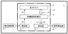
図1に、光通信用光学系,光通信装置の一実施の形態を模式的に示す。光通信装置1は、基地局と末端機との間での光通信に用いられる末端機側の送受信用装置であり、光通信用光学系2,発光制御部7,信号検出部8等で構成されている。光学系2は、光ファイバ3,体積型回折格子4,発光部5,受光部6等を備えており、光ファイバ3は、送信情報を有する光束S1を外部に伝送し、受信情報を有する光束L1,L2を外部から取り込む構成になっている。体積型回折格子4は、発光部5からの光束S1を光ファイバ3に入射させ、光ファイバ3からの光束L1,L2を分岐して受光部6に入射させる。光束S1,L1,L2の波長帯域は互いに異なっており、光束S1は短波長帯域の光から成っており、光束L1,L2は長波長帯域の光から成っている。つまり、発光部5から体積型回折格子4に対し短波長帯域の光束S1が射出され、光ファイバ3から体積型回折格子4に対し長波長帯域の光束L1,L2が射出される。なお、各波長帯域の数は上記場合に限るものではなく、採用する規格に応じて設定される。
FIG. 1 schematically shows an embodiment of an optical system for optical communication and an optical communication apparatus. The
発光部5は、例えばLD(laser diode)等により構成され、その発光の制御を発光制御部7が行うことにより、発光部5から射出する光束S1に送信情報を載せる。受光部6は、光束L1,L2を受ける光学要素であり、2チャンネルの波長帯域の光に対応可能となっている。例えば、受光部6に光ファイバを用いる場合、2本の光ファイバを並べて、それらの端面で受光面を構成する。受光面から光ファイバに入射した光束L1,L2は、例えば、PD(photodiode)等の光電変換素子で受光量を表す信号に変換され、その出力信号を信号検出部8が検出することにより、光束L1,L2の受信情報を電気信号として出力する。光ファイバを用いずに、2つの光電変換素子(PD等)で受光部6の受光面を構成してもよい。その場合、光電変換素子は受光素子面で光束L1,L2を直接受光し、受光量を表す信号を出力する。その出力信号を信号検出部8が検出して、光束L1,L2が持っている受信情報を電気信号として出力する。
The
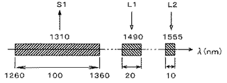
ここで、図1の実施の形態で採用している、光通信分野での3波BIDI規格を説明する。図2に、3波BIDI規格の通信において分岐・結合される波長帯域を示す。3波BIDI規格は上り1波,下り2波の通信規格である。上りは末端機から基地局への送信であって、1310nmチャンネル,帯域幅(bandwidth)100nm(1260〜1360nm)である。一方、下りは基地局から末端機への送信であって、1490nmチャンネル,帯域幅20nm;1555nmチャンネル,帯域幅10nmである。
Here, the three-wave BIDI standard in the optical communication field employed in the embodiment of FIG. 1 will be described. FIG. 2 shows wavelength bands that are branched and combined in the three-wave BIDI standard communication. The 3-wave BIDI standard is an upstream 1-wave and downstream 2-wave communication standard. Uplink is transmission from the terminal device to the base station, and has a 1310 nm channel and a bandwidth of 100 nm (1260 to 1360 nm). On the other hand, the downlink is transmission from the base station to the terminal, and has a 1490 nm channel, a
離散的に異なる複数のチャンネル周波数を分岐・結合するのに適した体積型回折格子4の構成を以下に検討する。体積型回折格子において、等間隔平行の層構造による屈折率変調の周期(層の間隔)と、格子面に入射する角度と、をブラッグ回折となるようにすれば、回折効率を大きくすることができる。そのとき、回折格子基板面の向き又は回折格子基板面の法線方向とブラッグ回折とは無関係である。したがって、回折格子基板面の向きと独立して体積型回折格子の層方向を設定することにより、入射光及び回折光の回折格子基板面に対する方向を任意に定めることが可能である。そして、この特性を利用することにより、体積型回折格子の回折格子基板面に対して垂直又は略垂直に入射する光線を波長分岐することが可能となり、これにより光路長を短縮することができるため光学系の小型化が可能となる。また、そのような体積型回折格子を複数枚重ねて配置することにより、多チャンネル分岐をコンパクトな構成で実現することが可能となる。 The configuration of the volume diffraction grating 4 suitable for branching / combining a plurality of discretely different channel frequencies will be discussed below. In a volume type diffraction grating, if the period of refractive index modulation (layer spacing) due to a parallel layer structure with equal intervals and the angle of incidence on the grating surface are set to be Bragg diffraction, the diffraction efficiency can be increased. it can. At that time, the direction of the diffraction grating substrate surface or the normal direction of the diffraction grating substrate surface is independent of Bragg diffraction. Therefore, by setting the layer direction of the volume type diffraction grating independently of the direction of the diffraction grating substrate surface, it is possible to arbitrarily determine the direction of incident light and diffracted light with respect to the diffraction grating substrate surface. By utilizing this characteristic, it becomes possible to branch the wavelength of light incident perpendicularly or substantially perpendicularly to the diffraction grating substrate surface of the volume type diffraction grating, thereby shortening the optical path length. The optical system can be miniaturized. Further, by arranging a plurality of such volume type diffraction gratings in a stacked manner, multi-channel branching can be realized with a compact configuration.
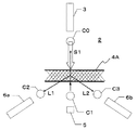
表1に、屈折率n=1.5,屈折率変調量Δn=0.01で構成された体積型回折格子4Aの仕様と性能を示し、図3に、体積型回折格子4Aと光束S1,L1,L2との関係を示す。体積型回折格子4Aの格子傾き角度αは、回折格子基板面4sの法線から左回りを正とする。回折格子基板面4sの法線に対して屈折率変調の方向が成す角度をβとすると、|α|+|β|=90度である。図3に示すように、周期Λは回折格子基板面4sに対し平行な方向にとっており、表1中のΔn幅は(n+Δn)の屈折率を有する媒質の幅に相当する。また、PDL(Polarization Dependent Loss)は偏光依存性を評価する数値であり、これは偏光の効率比の(10を底とする)対数の10倍(絶対値)で表される。PDLは小さいほど良く、実用的には下り信号について1〜2程度以下が必要である。
Table 1 shows the specifications and performance of the volume
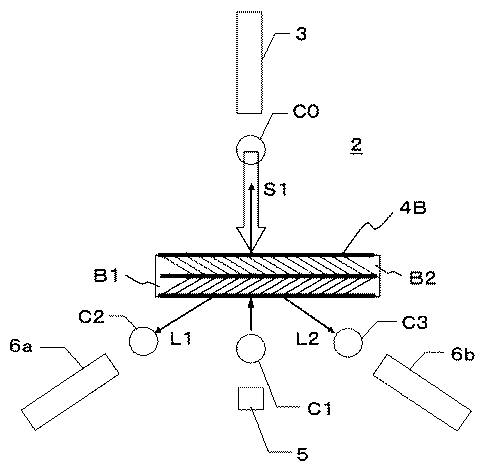
図3に示すように、上り信号の光束S1及び下り信号の光束L1,L2は、いずれも回折格子基板面4sに対して垂直に入射する。直進する非回折光(透過光)が1310nmチャンネルの上り信号であり、正方向に偏向する回折光が1490nmチャンネルの下り信号であり、負方向に偏向する回折光が1555nmチャンネルの下り信号である。体積型回折格子4Aの材料内には、格子傾き角度αが正負の2種類の方向の屈折率変調があるため、一方の屈折率変調による回折光に対して他方の屈折率変調による回折光は異なる象限に回折されることになる。ここでは、一方の回折光が1490nmチャンネルに相当し、他方の回折光が1555nmチャンネルに相当する。なお、回折格子仕様に対応する、単一方向の屈折率変調の体積型回折格子を2枚積層しても同等の特性が得られる。
As shown in FIG. 3, both the upstream signal beam S1 and the downstream signal beams L1 and L2 are perpendicularly incident on the diffraction grating substrate surface 4s. Non-diffracted light (transmitted light) traveling straight is an upstream signal of the 1310 nm channel, diffracted light deflected in the positive direction is a downstream signal of the 1490 nm channel, and diffracted light deflected in the negative direction is a downstream signal of the 1555 nm channel. In the material of the volume
図4に、体積型回折格子4Aでの各回折光の波長と効率との関係をグラフで示す。それぞれ波長依存性が大きく効率が大きくなる箇所でチャンネル中心波長程度となる。なお凡例中のp,sは偏光を示している。
FIG. 4 is a graph showing the relationship between the wavelength of each diffracted light and the efficiency in the volume
図5に、上述した体積型回折格子4A(第1のタイプの体積型回折格子)を有する光通信用光学系2の一例を示す。図5において、C0〜C3はコリメータレンズ(例えばボールレンズ)であり、受光部6a,6bは前記受光部6(図1)に相当するものである。
FIG. 5 shows an example of an optical system for
基地局へとつながる光ファイバ3の端面からは下り信号の光束L1,L2が発散し、コリメータレンズC0(ボールレンズ等)でコリメートされた後、体積型回折格子4Aに入射する。そして、体積型回折格子4Aにより回折されて、1490nmチャンネル帯域の光束L1と1555nmチャンネル帯域の光束L2とに分光される。回折後の光束L1,L2は、コリメータレンズ(ボールレンズ等)C2,C3によりそれぞれ集光され、受光部6a,6bに対してそれぞれ結像する。つまり、光束L1はコリメータレンズC2での集光により受光部6aへと結合され、光束L2はコリメータレンズC3での集光により受光部6bへと結合される。なお、受光部6a,6bとしては、例えば光ファイバ又は光電変換素子が用いられる。
Downstream light beams L1 and L2 diverge from the end face of the
一方、上り信号を構成する発光部(例えばLD)5aから発散される1310nmチャンネル帯域の光束S1は、コリメータレンズC1(ボールレンズ等)でコリメートされた後、体積型回折格子4Aを非回折で透過する。そして、コリメータレンズC0(ボールレンズ等)で集光された後、光ファイバ3の端面で結像する。このとき、1310nmチャンネル帯域の光束S1は非回折であるため、波長分散によるスポットの拡大が生じない。このため、シングルモードファイバ等のコア径(つまりファイバ受光部)の小さな物に対しても効率良い結合が可能となる。
On the other hand, the light beam S1 in the 1310 nm channel band that diverges from the light emitting unit (for example, LD) 5a constituting the upstream signal is collimated by the collimator lens C1 (ball lens or the like) and then transmitted non-diffracted through the volume
次に、体積型回折格子4の作製方法を説明する。その作製方法は2種類考えられ、第1の作製方法は二光束干渉露光法であり、第2の作製方法は異なる屈折率の層を積層する方法である。二光束干渉露光法は、互いにコヒーレントな光束の干渉縞を感光性ポリマー材料中に記録することにより行われる。露光波長又は干渉角度(二光束のなす角度)、基板に対する入射角度を変えることにより、任意の周期と格子傾き角度を有する屈折率変調の体積型回折格子を作製することが可能である。二光束の入射角度を異なるように配置することにより、回折格子基板面に対して傾いた格子角度とすることが可能である。また、体積型回折格子4Aのように1つの基板中に複数の屈折率変調を有するものは、それぞれの屈折率変調を二光束干渉露光で形成することにより作製可能である。
Next, a method for manufacturing the
第2の作製方法は、屈折率の異なる厚み1〜2μmの層を積層することにより行われる。積層方法としては2種類考えられる。第1の積層方法は塗布によるものであり、2種類の屈折率材料を厚み1〜2μmで交互に塗布することで積層が行われる。第2の積層方法はフィルムの積層によるものであり、2種類の屈折率材料フィルム(厚み20μm程度)を接着又は融着で積層し、圧延工程により所望の厚みとすることで積層が行われる。これらの積層方法により積層されたものを所望の厚みと方向で切り出すことにより、任意の周期と格子傾き角度を有する屈折率変調の体積型回折格子を作製することが可能である。また、そのような体積型回折格子を複数枚重ねて配置することにより、多チャンネル分岐をコンパクトな構成で実現することが可能となる。 The second manufacturing method is performed by laminating layers having different refractive indexes and thicknesses of 1 to 2 μm. There are two possible lamination methods. The first laminating method is based on coating, and laminating is performed by alternately coating two types of refractive index materials with a thickness of 1 to 2 μm. The second laminating method is by laminating films, and laminating is performed by laminating two kinds of refractive index material films (thickness of about 20 μm) by adhesion or fusion, and by making a desired thickness by a rolling process. By cutting out the layers laminated by these lamination methods in a desired thickness and direction, it is possible to produce a refractive index modulated volume type diffraction grating having an arbitrary period and grating inclination angle. Further, by arranging a plurality of such volume type diffraction gratings in a stacked manner, multi-channel branching can be realized with a compact configuration.
図6に、1種類の屈折率変調を有する体積型回折格子を2枚積層して成る体積型回折格子4B(第2のタイプの体積型回折格子)を有する光通信用光学系2の一例を示す。図6に示す光通信用光学系2は、体積型回折格子のタイプが異なるほかは図5に示すものと同じ構成を有している。体積型回折格子4Bは、1490nmチャンネル帯域の光束L1を分離するための体積型回折格子B1と、1555nmチャンネル帯域の光束L2を分離するための体積型回折格子B2と、から成っている。表2に、体積型回折格子B1,B2の仕様と性能を示す。
FIG. 6 shows an example of an optical system for
以上説明した各形態の特徴は、離散的に異なる複数の波長帯域を分岐・結合する光学系,それを備えた光通信装置における適用において一般化が可能である。例えば光通信用光学系は、離散的に異なる複数の波長帯域を分岐・結合する光通信用光学系であって、周期的な屈折率変調により回折を行う体積型回折格子を有し、その屈折率変調の方向が回折格子基板面の法線に対して垂直ではなく、前記複数の波長帯域における任意の光線の波長について、短波長帯域の光が前記体積型回折格子を非回折で透過し、長波長帯域の光が前記体積型回折格子で回折され、前記体積型回折格子に対する各波長帯域の入射光及び短波長帯域の透過光が回折格子基板面に対して垂直又は略垂直であることが望ましい。 The features of the embodiments described above can be generalized in applications in an optical system that branches and combines a plurality of discretely different wavelength bands and an optical communication apparatus including the optical system. For example, an optical communication optical system is an optical communication optical system that branches and combines a plurality of discretely different wavelength bands, and has a volume diffraction grating that performs diffraction by periodic refractive index modulation. The direction of the rate modulation is not perpendicular to the normal line of the diffraction grating substrate surface, and the light of a short wavelength band passes through the volume diffraction grating non-diffractingly about the wavelength of an arbitrary light beam in the plurality of wavelength bands, Long wavelength band light is diffracted by the volume diffraction grating, and incident light of each wavelength band and transmitted light of short wavelength band with respect to the volume diffraction grating are perpendicular or substantially perpendicular to the diffraction grating substrate surface. desirable.
この構成により、光路長を縮小することができるため、体積型回折格子を用いても小型化・低コスト化が可能であり、離散的に異なる複数の波長帯域を分岐することが可能である。また、短波長帯域の光が体積型回折格子を非回折で透過する構成では、例えば、光通信における上り短波長帯域でのスポット径を小さくして良好な光結合を達成することが可能となる。 With this configuration, since the optical path length can be reduced, it is possible to reduce the size and cost even if a volume diffraction grating is used, and it is possible to branch a plurality of discretely different wavelength bands. Further, in a configuration in which light in a short wavelength band is transmitted through a volume diffraction grating without diffraction, for example, it is possible to reduce the spot diameter in the short wavelength band in optical communication and achieve good optical coupling. .
前記屈折率変調の方向が回折格子基板面の法線に対して60°〜80°であり、以下の条件式(1)を満足することが望ましい。
10000<h/(Δn・Λ)<15000 …(1)
ただし、
h:体積型回折格子の基板厚み、
Λ:体積型回折格子の屈折率変調の周期、
Δn:体積型回折格子の屈折率変調量、
である。
It is desirable that the direction of the refractive index modulation is 60 ° to 80 ° with respect to the normal line of the diffraction grating substrate surface, and the following conditional expression (1) is satisfied.
10000 <h / (Δn · Λ) <15000 (1)
However,
h: substrate thickness of volume type diffraction grating,
Λ: period of refractive index modulation of volume type diffraction grating,
Δn: Refractive index modulation amount of volume type diffraction grating,
It is.
図3において、屈折率変調の方向が回折格子基板面4sの法線に対して成す角度βは、90°−|α|に相当するので、例えば、α=16.97°の場合にはβ=73.03°、α=−17.84°の場合にはβ=72.16°である。この条件範囲の下限値(60°)を下回ると、回折効率を高くするために周期Λを小さくする必要が生じるため、体積型回折格子の作製が困難になる。逆に、条件範囲の上限値(80°)を上回ると、回折効率を高くするために回折格子基板を傾けて構成する必要が生じるため、光路長が長くなることにより光学系の小型化が阻害されてしまう。 In FIG. 3, the angle β formed by the direction of the refractive index modulation with respect to the normal line of the diffraction grating substrate surface 4s corresponds to 90 ° − | α |. For example, when α = 16.97 °, β = 73.03 °, α = -17.84 °, β = 72.16 °. Below the lower limit (60 °) of this condition range, it is necessary to reduce the period Λ in order to increase the diffraction efficiency, making it difficult to produce a volume diffraction grating. Conversely, if the upper limit of the condition range (80 °) is exceeded, the diffraction grating substrate needs to be tilted in order to increase the diffraction efficiency. Will be.
また、条件式(1)の下限を下回ると、波長選択性が弱くなるため、透過光である1310nmチャンネルの効率低下を招くことになる。逆に、条件式(1)の上限を上回ると、波長選択性が強くなりすぎるため、帯域幅の上限・下限で回折効率の低下が発生する。なお、前述した具体的な数値:Λ=1.79(μm),h=233(μm),Δn=0.01を用いた条件式(1)の対応値:h/(Λ・Δn)=13017である。 On the other hand, if the lower limit of conditional expression (1) is not reached, the wavelength selectivity becomes weak, which leads to a decrease in efficiency of the 1310 nm channel that is transmitted light. On the other hand, if the upper limit of conditional expression (1) is exceeded, the wavelength selectivity becomes too strong, and the diffraction efficiency decreases at the upper and lower limits of the bandwidth. Incidentally, the above-mentioned specific numerical values: Λ = 1.79 (μm), h = 233 (μm), and the corresponding value of the conditional expression (1) using Δn = 0.01: h / (Λ · Δn) = 13017.
体積型回折格子は、前述したように、フィルムを積層し圧延することにより作製可能であり、塗布により形成されるフィルムの積層により作製可能である。また、体積型回折格子が2種類以上の屈折率変調を有することにより多分岐が可能となり、光学系の小型化を効果的に達成することが可能となる。その場合、1つの材料中に2種類以上の屈折率変調を有する構成でもよく、1つの材料中に1種類の屈折率変調を有する体積型回折格子を2以上積層する構成でもよい。 As described above, the volume diffraction grating can be produced by laminating and rolling a film, and can be produced by laminating films formed by coating. Further, since the volume type diffraction grating has two or more types of refractive index modulation, multi-branching is possible, and it is possible to effectively reduce the size of the optical system. In that case, the structure which has two or more types of refractive index modulation in one material may be sufficient, and the structure which laminates | stacks two or more volume type diffraction gratings which have one type of refractive index modulation in one material may be sufficient.
1 光通信装置
2 光通信用光学系
3 光ファイバ
4,4A,4B 体積型回折格子
4s 回折格子基板面
5 発光部(LD)
6,6a,6b 受光部(PD,光ファイバ)
7 発光制御部
8 信号検出部
C0〜C3 コリメータレンズ(ボールレンズ)
S1 短波長帯域の光束
L1,L2 長波長帯域の光束
DESCRIPTION OF
6, 6a, 6b Light-receiving part (PD, optical fiber)
7 Light
S1 Light flux in short wavelength band L1, L2 Light flux in long wavelength band
Claims (6)
10000<h/(Δn・Λ)<15000 …(1)
ただし、
h:体積型回折格子の基板厚み、
Λ:体積型回折格子の屈折率変調の周期、
Δn:体積型回折格子の屈折率変調量、
である。 An optical system for optical communication that branches and couples a plurality of discrete wavelength bands, and has a volume type diffraction grating that performs multiple diffractions by two or more types of periodic refractive index modulation. None of the directions are perpendicular to the normal of the diffraction grating substrate surface, and light of a short wavelength band passes through the volume type diffraction grating in a non-diffracting manner with respect to the wavelength of an arbitrary ray in the plurality of wavelength bands, A plurality of light in a long wavelength band is diffracted by the volume diffraction grating, and incident light in each wavelength band and transmitted light in a short wavelength band with respect to the volume diffraction grating are perpendicular or substantially perpendicular to the diffraction grating substrate surface. Ri, any direction of the refractive index modulation is 60 ° to 80 ° to the normal of the diffraction grating substrate surface, characterized that you satisfied even following condition for any of the refractive index modulation (1) Optical communication optical system ;
10000 <h / (Δn · Λ) <15000 (1)
However,
h: substrate thickness of volume type diffraction grating,
Λ: period of refractive index modulation of volume type diffraction grating,
Δn: Refractive index modulation amount of volume type diffraction grating,
It is .
Priority Applications (1)
| Application Number | Priority Date | Filing Date | Title |
|---|---|---|---|
| JP2006152713A JP5145656B2 (en) | 2006-05-31 | 2006-05-31 | Optical system for optical communication and optical communication apparatus |
Applications Claiming Priority (1)
| Application Number | Priority Date | Filing Date | Title |
|---|---|---|---|
| JP2006152713A JP5145656B2 (en) | 2006-05-31 | 2006-05-31 | Optical system for optical communication and optical communication apparatus |
Publications (2)
| Publication Number | Publication Date |
|---|---|
| JP2007322739A JP2007322739A (en) | 2007-12-13 |
| JP5145656B2 true JP5145656B2 (en) | 2013-02-20 |
Family
ID=38855604
Family Applications (1)
| Application Number | Title | Priority Date | Filing Date |
|---|---|---|---|
| JP2006152713A Expired - Fee Related JP5145656B2 (en) | 2006-05-31 | 2006-05-31 | Optical system for optical communication and optical communication apparatus |
Country Status (1)
| Country | Link |
|---|---|
| JP (1) | JP5145656B2 (en) |
Family Cites Families (10)
| Publication number | Priority date | Publication date | Assignee | Title |
|---|---|---|---|---|
| JPS5342043A (en) * | 1976-09-28 | 1978-04-17 | Nec Corp | Optical multichannel system |
| JPS5455456A (en) * | 1977-10-12 | 1979-05-02 | Canon Inc | Method of composing and separating plural beams |
| JPS61221723A (en) * | 1985-10-25 | 1986-10-02 | Canon Inc | Method for multiplexing plural beams |
| JPS6236628A (en) * | 1986-07-26 | 1987-02-17 | Canon Inc | Method for synthesizing plural beams |
| JP3157852B2 (en) * | 1991-06-12 | 2001-04-16 | シャープ株式会社 | Unidirectional optical transmission module |
| JPH05288910A (en) * | 1992-04-14 | 1993-11-05 | Dainippon Printing Co Ltd | Diffraction grating |
| JPH07104154A (en) * | 1993-10-07 | 1995-04-21 | Hitachi Ltd | Optical transmission module and optical transmitting device |
| JPH07281015A (en) * | 1994-04-08 | 1995-10-27 | Hideo Shingu | Manufacture of laminated optical grating |
| JP2003322764A (en) * | 2002-04-30 | 2003-11-14 | Alps Electric Co Ltd | Optical communication module |
| JP2005275060A (en) * | 2004-03-25 | 2005-10-06 | Konica Minolta Holdings Inc | Optical element and optical communication module |
-
2006
- 2006-05-31 JP JP2006152713A patent/JP5145656B2/en not_active Expired - Fee Related
Also Published As
| Publication number | Publication date |
|---|---|
| JP2007322739A (en) | 2007-12-13 |
Similar Documents
| Publication | Publication Date | Title |
|---|---|---|
| CN103999303B (en) | Integrated sub-wave length grating system | |
| US6449066B1 (en) | Polarization insensitive, high dispersion optical element | |
| US9485046B1 (en) | Optical spot array pitch compressor | |
| US20100290128A1 (en) | Optical module | |
| WO2002021169A1 (en) | Optical element having wavelength selectivity | |
| US7403681B2 (en) | Wavelength selective optical device and method of tuning wavelength characteristics | |
| US6999663B2 (en) | Fiber optic tap | |
| EP1312181A2 (en) | Device and method for optical performance monitoring in an optical communications network | |
| US6724533B2 (en) | Lamellar grating structure with polarization-independent diffraction efficiency | |
| JP5145656B2 (en) | Optical system for optical communication and optical communication apparatus | |
| JP4505313B2 (en) | Optical device and optical control method | |
| US6829096B1 (en) | Bi-directional wavelength division multiplexing/demultiplexing devices | |
| JP2000131542A (en) | Optical transmission and reception module | |
| US20040156596A1 (en) | Fiber optic tap with compensated spectral filter | |
| US20040201892A1 (en) | Diffraction grating element, optical module and optical communications system | |
| JP2004240215A (en) | Optical communication device and optical communication system | |
| JP4816258B2 (en) | Optical device with surface reflection diffraction grating | |
| JP3933062B2 (en) | Wavelength division duplexer | |
| JP2010060653A (en) | Optical device and optical signal selection method | |
| JP2002169054A (en) | Device for multiplexing and branching wavelengths | |
| US20050031257A1 (en) | Optical component with spectral separation | |
| JPS58106516A (en) | Optical demultiplexer | |
| JP2008242450A (en) | Optical multiplexer/demultiplexer and optical transmitter-receiver using the same | |
| JP2004309650A (en) | Diffraction grating element, optical module, and optical communication system | |
| JP6134713B2 (en) | Wavelength multiplexer / demultiplexer, optical module, and server using the same |
Legal Events
| Date | Code | Title | Description |
|---|---|---|---|
| A621 | Written request for application examination |
Free format text: JAPANESE INTERMEDIATE CODE: A621 Effective date: 20090428 |
|
| RD03 | Notification of appointment of power of attorney |
Free format text: JAPANESE INTERMEDIATE CODE: A7423 Effective date: 20120425 |
|
| A131 | Notification of reasons for refusal |
Free format text: JAPANESE INTERMEDIATE CODE: A131 Effective date: 20120703 |
|
| A521 | Written amendment |
Free format text: JAPANESE INTERMEDIATE CODE: A523 Effective date: 20120830 |
|
| TRDD | Decision of grant or rejection written | ||
| A01 | Written decision to grant a patent or to grant a registration (utility model) |
Free format text: JAPANESE INTERMEDIATE CODE: A01 Effective date: 20121030 |
|
| A61 | First payment of annual fees (during grant procedure) |
Free format text: JAPANESE INTERMEDIATE CODE: A61 Effective date: 20121112 |
|
| R150 | Certificate of patent (=grant) or registration of utility model |
Free format text: JAPANESE INTERMEDIATE CODE: R150 |
|
| FPAY | Renewal fee payment (prs date is renewal date of database) |
Free format text: PAYMENT UNTIL: 20151207 Year of fee payment: 3 |
|
| S533 | Written request for registration of change of name |
Free format text: JAPANESE INTERMEDIATE CODE: R313533 |
|
| R350 | Written notification of registration of transfer |
Free format text: JAPANESE INTERMEDIATE CODE: R350 |
|
| LAPS | Cancellation because of no payment of annual fees |