JP5144510B2 - Microneedle array application device - Google Patents
Microneedle array application device Download PDFInfo
- Publication number
- JP5144510B2 JP5144510B2 JP2008519435A JP2008519435A JP5144510B2 JP 5144510 B2 JP5144510 B2 JP 5144510B2 JP 2008519435 A JP2008519435 A JP 2008519435A JP 2008519435 A JP2008519435 A JP 2008519435A JP 5144510 B2 JP5144510 B2 JP 5144510B2
- Authority
- JP
- Japan
- Prior art keywords
- patch
- microneedle array
- microneedle
- application device
- housing
- Prior art date
- Legal status (The legal status is an assumption and is not a legal conclusion. Google has not performed a legal analysis and makes no representation as to the accuracy of the status listed.)
- Active
Links
- 239000011248 coating agent Substances 0.000 claims description 7
- 238000000576 coating method Methods 0.000 claims description 7
- 210000003491 skin Anatomy 0.000 description 54
- 230000001133 acceleration Effects 0.000 description 26
- 230000007246 mechanism Effects 0.000 description 17
- 239000003814 drug Substances 0.000 description 10
- 238000000034 method Methods 0.000 description 10
- 230000037317 transdermal delivery Effects 0.000 description 9
- 239000000853 adhesive Substances 0.000 description 7
- 230000001070 adhesive effect Effects 0.000 description 7
- 210000000434 stratum corneum Anatomy 0.000 description 7
- 238000003491 array Methods 0.000 description 6
- 230000014759 maintenance of location Effects 0.000 description 6
- 229940124597 therapeutic agent Drugs 0.000 description 6
- 238000013461 design Methods 0.000 description 4
- 229940079593 drug Drugs 0.000 description 4
- 239000000758 substrate Substances 0.000 description 4
- 239000012530 fluid Substances 0.000 description 3
- 230000003116 impacting effect Effects 0.000 description 3
- 150000002605 large molecules Chemical class 0.000 description 3
- 229920002521 macromolecule Polymers 0.000 description 3
- 238000002493 microarray Methods 0.000 description 3
- 239000000126 substance Substances 0.000 description 3
- 230000008901 benefit Effects 0.000 description 2
- 238000006073 displacement reaction Methods 0.000 description 2
- 238000012377 drug delivery Methods 0.000 description 2
- 239000000463 material Substances 0.000 description 2
- 229910052751 metal Inorganic materials 0.000 description 2
- 239000002184 metal Substances 0.000 description 2
- 230000035515 penetration Effects 0.000 description 2
- 238000003825 pressing Methods 0.000 description 2
- 230000002035 prolonged effect Effects 0.000 description 2
- 238000005070 sampling Methods 0.000 description 2
- 210000001519 tissue Anatomy 0.000 description 2
- 229940122361 Bisphosphonate Drugs 0.000 description 1
- 108010041986 DNA Vaccines Proteins 0.000 description 1
- 229940021995 DNA vaccine Drugs 0.000 description 1
- CWYNVVGOOAEACU-UHFFFAOYSA-N Fe2+ Chemical compound [Fe+2] CWYNVVGOOAEACU-UHFFFAOYSA-N 0.000 description 1
- HTTJABKRGRZYRN-UHFFFAOYSA-N Heparin Chemical compound OC1C(NC(=O)C)C(O)OC(COS(O)(=O)=O)C1OC1C(OS(O)(=O)=O)C(O)C(OC2C(C(OS(O)(=O)=O)C(OC3C(C(O)C(O)C(O3)C(O)=O)OS(O)(=O)=O)C(CO)O2)NS(O)(=O)=O)C(C(O)=O)O1 HTTJABKRGRZYRN-UHFFFAOYSA-N 0.000 description 1
- DGAQECJNVWCQMB-PUAWFVPOSA-M Ilexoside XXIX Chemical compound C[C@@H]1CC[C@@]2(CC[C@@]3(C(=CC[C@H]4[C@]3(CC[C@@H]5[C@@]4(CC[C@@H](C5(C)C)OS(=O)(=O)[O-])C)C)[C@@H]2[C@]1(C)O)C)C(=O)O[C@H]6[C@@H]([C@H]([C@@H]([C@H](O6)CO)O)O)O.[Na+] DGAQECJNVWCQMB-PUAWFVPOSA-M 0.000 description 1
- 108091028043 Nucleic acid sequence Proteins 0.000 description 1
- 229910000639 Spring steel Inorganic materials 0.000 description 1
- 229910000831 Steel Inorganic materials 0.000 description 1
- 230000003213 activating effect Effects 0.000 description 1
- DCSBSVSZJRSITC-UHFFFAOYSA-M alendronate sodium trihydrate Chemical compound O.O.O.[Na+].NCCCC(O)(P(O)(O)=O)P(O)([O-])=O DCSBSVSZJRSITC-UHFFFAOYSA-M 0.000 description 1
- 239000003242 anti bacterial agent Substances 0.000 description 1
- 229940088710 antibiotic agent Drugs 0.000 description 1
- 150000004663 bisphosphonates Chemical class 0.000 description 1
- 229960004755 ceftriaxone Drugs 0.000 description 1
- VAAUVRVFOQPIGI-SPQHTLEESA-N ceftriaxone Chemical compound S([C@@H]1[C@@H](C(N1C=1C(O)=O)=O)NC(=O)\C(=N/OC)C=2N=C(N)SC=2)CC=1CSC1=NC(=O)C(=O)NN1C VAAUVRVFOQPIGI-SPQHTLEESA-N 0.000 description 1
- 238000004891 communication Methods 0.000 description 1
- 210000003811 finger Anatomy 0.000 description 1
- 229920002313 fluoropolymer Polymers 0.000 description 1
- 239000004811 fluoropolymer Substances 0.000 description 1
- 239000011888 foil Substances 0.000 description 1
- 150000004676 glycans Chemical class 0.000 description 1
- 229960002897 heparin Drugs 0.000 description 1
- 229920000669 heparin Polymers 0.000 description 1
- 230000028993 immune response Effects 0.000 description 1
- 238000011081 inoculation Methods 0.000 description 1
- 238000003780 insertion Methods 0.000 description 1
- 230000037431 insertion Effects 0.000 description 1
- 239000000696 magnetic material Substances 0.000 description 1
- 238000012986 modification Methods 0.000 description 1
- 230000004048 modification Effects 0.000 description 1
- 230000001537 neural effect Effects 0.000 description 1
- NJPPVKZQTLUDBO-UHFFFAOYSA-N novaluron Chemical compound C1=C(Cl)C(OC(F)(F)C(OC(F)(F)F)F)=CC=C1NC(=O)NC(=O)C1=C(F)C=CC=C1F NJPPVKZQTLUDBO-UHFFFAOYSA-N 0.000 description 1
- 239000002861 polymer material Substances 0.000 description 1
- 229920001282 polysaccharide Polymers 0.000 description 1
- 239000005017 polysaccharide Substances 0.000 description 1
- 229920001296 polysiloxane Polymers 0.000 description 1
- 238000005381 potential energy Methods 0.000 description 1
- 230000008569 process Effects 0.000 description 1
- 102000004196 processed proteins & peptides Human genes 0.000 description 1
- 108090000765 processed proteins & peptides Proteins 0.000 description 1
- 108090000623 proteins and genes Proteins 0.000 description 1
- 102000004169 proteins and genes Human genes 0.000 description 1
- 230000000717 retained effect Effects 0.000 description 1
- 150000003839 salts Chemical group 0.000 description 1
- 238000007789 sealing Methods 0.000 description 1
- 150000003384 small molecules Chemical class 0.000 description 1
- 229910052708 sodium Inorganic materials 0.000 description 1
- 239000011734 sodium Substances 0.000 description 1
- 239000010959 steel Substances 0.000 description 1
- 230000000638 stimulation Effects 0.000 description 1
- 238000013268 sustained release Methods 0.000 description 1
- 239000012730 sustained-release form Substances 0.000 description 1
- 230000001225 therapeutic effect Effects 0.000 description 1
- 210000003813 thumb Anatomy 0.000 description 1
- 230000000699 topical effect Effects 0.000 description 1
- 238000013271 transdermal drug delivery Methods 0.000 description 1
- 238000002255 vaccination Methods 0.000 description 1
- 229960005486 vaccine Drugs 0.000 description 1
- 239000012646 vaccine adjuvant Substances 0.000 description 1
- 229940124931 vaccine adjuvant Drugs 0.000 description 1
Images


Classifications
-
- A—HUMAN NECESSITIES
- A61—MEDICAL OR VETERINARY SCIENCE; HYGIENE
- A61M—DEVICES FOR INTRODUCING MEDIA INTO, OR ONTO, THE BODY; DEVICES FOR TRANSDUCING BODY MEDIA OR FOR TAKING MEDIA FROM THE BODY; DEVICES FOR PRODUCING OR ENDING SLEEP OR STUPOR
- A61M5/00—Devices for bringing media into the body in a subcutaneous, intra-vascular or intramuscular way; Accessories therefor, e.g. filling or cleaning devices, arm-rests
- A61M5/14—Infusion devices, e.g. infusing by gravity; Blood infusion; Accessories therefor
- A61M5/158—Needles for infusions; Accessories therefor, e.g. for inserting infusion needles, or for holding them on the body
-
- A—HUMAN NECESSITIES
- A61—MEDICAL OR VETERINARY SCIENCE; HYGIENE
- A61B—DIAGNOSIS; SURGERY; IDENTIFICATION
- A61B17/00—Surgical instruments, devices or methods, e.g. tourniquets
- A61B17/20—Surgical instruments, devices or methods, e.g. tourniquets for vaccinating or cleaning the skin previous to the vaccination
- A61B17/205—Vaccinating by means of needles or other puncturing devices
-
- A—HUMAN NECESSITIES
- A61—MEDICAL OR VETERINARY SCIENCE; HYGIENE
- A61M—DEVICES FOR INTRODUCING MEDIA INTO, OR ONTO, THE BODY; DEVICES FOR TRANSDUCING BODY MEDIA OR FOR TAKING MEDIA FROM THE BODY; DEVICES FOR PRODUCING OR ENDING SLEEP OR STUPOR
- A61M37/00—Other apparatus for introducing media into the body; Percutany, i.e. introducing medicines into the body by diffusion through the skin
- A61M37/0015—Other apparatus for introducing media into the body; Percutany, i.e. introducing medicines into the body by diffusion through the skin by using microneedles
-
- A—HUMAN NECESSITIES
- A61—MEDICAL OR VETERINARY SCIENCE; HYGIENE
- A61M—DEVICES FOR INTRODUCING MEDIA INTO, OR ONTO, THE BODY; DEVICES FOR TRANSDUCING BODY MEDIA OR FOR TAKING MEDIA FROM THE BODY; DEVICES FOR PRODUCING OR ENDING SLEEP OR STUPOR
- A61M5/00—Devices for bringing media into the body in a subcutaneous, intra-vascular or intramuscular way; Accessories therefor, e.g. filling or cleaning devices, arm-rests
- A61M5/14—Infusion devices, e.g. infusing by gravity; Blood infusion; Accessories therefor
- A61M5/158—Needles for infusions; Accessories therefor, e.g. for inserting infusion needles, or for holding them on the body
- A61M2005/1585—Needle inserters
-
- A—HUMAN NECESSITIES
- A61—MEDICAL OR VETERINARY SCIENCE; HYGIENE
- A61M—DEVICES FOR INTRODUCING MEDIA INTO, OR ONTO, THE BODY; DEVICES FOR TRANSDUCING BODY MEDIA OR FOR TAKING MEDIA FROM THE BODY; DEVICES FOR PRODUCING OR ENDING SLEEP OR STUPOR
- A61M37/00—Other apparatus for introducing media into the body; Percutany, i.e. introducing medicines into the body by diffusion through the skin
- A61M37/0015—Other apparatus for introducing media into the body; Percutany, i.e. introducing medicines into the body by diffusion through the skin by using microneedles
- A61M2037/0023—Drug applicators using microneedles
Description
(関連出願に対する相互対照)
本出願は、2005年6月27日出願の米国仮特許出願第60/694,447号及び2006年5月3日出願の米国仮特許出願第60/746,298号の優先権を主張し、それらの全体が本明細書に記載されているものとみなす。
(Mutual contrast for related applications)
This application claims priority to US Provisional Patent Application No. 60 / 694,447 filed June 27, 2005 and US Provisional Patent Application No. 60 / 746,298 filed May 3, 2006, All of which are considered to be described herein.
(発明の分野)
本発明は、マイクロニードルアレイ適用装置及びマイクロニードルアレイを適用する方法に関する。
(Field of Invention)
The present invention relates to a microneedle array application apparatus and a method of applying a microneedle array.
治療的価値が実証された分子は、支援のない、又は受動的な経皮的薬物送達を介して、皮膚を通して限定数しか運搬することができない。皮膚を通して分子を運搬することに対する主な障害は、角質層(皮膚の最も外側の層)である。 Molecules that have demonstrated therapeutic value can only be transported through the skin through unassisted or passive transdermal drug delivery. The main obstacle to carrying molecules through the skin is the stratum corneum (the outermost layer of the skin).
治療薬及び他の物質を、皮膚又は他の表面を通して送達することに関連して使用される、マイクロニードル又はマイクロピンと称されることがある、比較的小さな構造のアレイを包含する装置が開示されてきた。装置は、典型的には、角質層に孔をあけて、治療薬及び他の物質が角質層を通過し、その下の組織に入り込むことができるようにするために、皮膚に押し付けられる。マイクロニードルは、マイクロニードルアレイを支える貼付剤を使用して送達することができ、それは、治療薬及び他の物質の送達を容易にする。 Disclosed is a device that includes an array of relatively small structures, sometimes referred to as microneedles or micropins, used in connection with delivering therapeutic agents and other substances through the skin or other surface. I came. The device is typically pressed against the skin to puncture the stratum corneum and allow therapeutic agents and other substances to pass through the stratum corneum and enter the underlying tissue. Microneedles can be delivered using patches that support the microneedle array, which facilitates the delivery of therapeutic agents and other substances.
マイクロニードルアレイ及び貼付剤は、多くの異なる回数使用することができる適用装置を用いて配置することができる。マイクロニードルアレイ及び貼付剤は、一般に、一度使用され、廃棄される。適用装置には、新しいマイクロニードルアレイ及び貼付剤を繰り返し再装填することができる。 The microneedle array and patch can be placed using an application device that can be used many different times. Microneedle arrays and patches are generally used once and discarded. The application device can be repeatedly reloaded with a new microneedle array and patch.
本発明は、代替マイクロニードルアレイ適用装置を提供する。 The present invention provides an alternative microneedle array application device.
本発明の第1の態様では、マイクロニードルアレイ適用装置は、ハウジング及び衝突体を包含する。ハウジングは、目標部位に配置される開口部を画定する、肌当て面を有する。衝突体は、マイクロニードルアレイを衝突して、マイクロニードルアレイを目標部位に向かって加速させることができる。衝突体は、更に、弓状の経路に沿って動いて、マイクロニードルアレイを目標部位に向かって動かすことができる。 In the first aspect of the present invention, the microneedle array application device includes a housing and a collision body. The housing has a skin contact surface that defines an opening disposed at the target site. The colliding body can collide with the microneedle array and accelerate the microneedle array toward the target site. The impactor can also move along an arcuate path to move the microneedle array toward the target site.
本発明の別の態様では、マイクロニードル適用装置は、開口部と共に肌当て面を有するハウジングと、ハウジングに取り付けられた固定端部から可動端部まで延びる長さを有する駆動部材とを包含する。駆動部材はその長さ部分に沿って屈曲可能であり、駆動部材の可動端部は、マイクロニードルアレイに接触して推進させることができるように構成される。一実施形態では、駆動部材は板ばねを含む。 In another aspect of the present invention, the microneedle application device includes a housing having a skin contact surface together with an opening, and a drive member having a length extending from a fixed end attached to the housing to a movable end. The drive member is bendable along its length, and the movable end of the drive member is configured to be propelled in contact with the microneedle array. In one embodiment, the drive member includes a leaf spring.
本発明の別の態様では、適用装置は、ハウジング、ハウジングによって旋回可能に支持された衝突体、及びねじりばねを包含する。衝突体は、第1の位置と第2の位置の間で実質的に弓状の経路に沿って動くことができる衝突部分を有する。ねじりばねは、衝突体をハウジングに対して付勢することができる。 In another aspect of the invention, the application device includes a housing, an impactor pivotably supported by the housing, and a torsion spring. The impactor has an impact portion that can move along a substantially arcuate path between a first position and a second position. The torsion spring can bias the impactor against the housing.
本発明の別の態様では、マイクロニードル適用装置は、肌当て面を有するハウジングを包含する。ハウジングの肌当て面に沿って窪みが画定され、窪みは底部分を有する。窪みの底部分内には開口部が画定され、開口部は目標部位の上に配置することができる。目標部位に適用する前に、マイクロニードルアレイを支える貼付剤を保持するため、少なくとも1つの保持面が、窪みの底部分に沿って、且つ開口部に隣接して配置される。保持面は窪みの底部分にほぼ平行であり、マイクロニードルアレイは開口部の下に整列させることができる。 In another aspect of the invention, the microneedle application device includes a housing having a skin contact surface. A recess is defined along the skin-bearing surface of the housing, and the recess has a bottom portion. An opening is defined in the bottom portion of the depression, and the opening can be disposed over the target site. Prior to application to the target site, at least one retaining surface is disposed along the bottom portion of the recess and adjacent to the opening to retain the patch that supports the microneedle array. The holding surface is substantially parallel to the bottom portion of the depression and the microneedle array can be aligned below the opening.
本発明の別の態様では、マイクロニードルアレイ適用装置は、ハウジング及び衝突体を包含する。ハウジングは、目標部位に配置される開口部を画定する肌当て面を有する。衝突体は、マイクロニードルアレイを衝突して、マイクロニードルアレイを目標部位に向かって加速させることができる。衝突体は、磁気マイクロニードル貼付剤を解放可能に保持するのに適した磁石を含む。 In another aspect of the invention, the microneedle array application device includes a housing and an impactor. The housing has a skin contact surface that defines an opening disposed at the target site. The colliding body can collide with the microneedle array and accelerate the microneedle array toward the target site. The impactor includes a magnet suitable for releasably holding the magnetic microneedle patch.
本発明の別の態様では、マイクロニードルアレイを適用する方法は、マイクロニードルアレイを目標部位に向かって加速させることができる、マイクロニードルアプリケーション装置を提供する工程と、マイクロニードルアレイをマイクロニードルアレイアプリケーション装置上に実装する工程と、マイクロニードルアレイを、実質的に弓状の経路に沿って目標部位に向かって移動する工程とを包含する。 In another aspect of the present invention, a method of applying a microneedle array includes providing a microneedle application device that can accelerate the microneedle array toward a target site; and Mounting on the device, and moving the microneedle array along a substantially arcuate path toward the target site.
本発明の別の態様では、マイクロニードルアレイを適用する方法は、マイクロニードルアレイを目標部位に向かわせることができるマイクロニードル適用装置を提供する工程と、マイクロニードルアレイをマイクロニードルアレイ適用装置上に実装する工程と、衝突体を実質的に弓状の経路に沿って移動して、マイクロニードルアレイを目標部位と接触させる工程とを包含する。 In another aspect of the present invention, a method of applying a microneedle array includes providing a microneedle application device capable of directing the microneedle array to a target site, and placing the microneedle array on the microneedle array application device. Mounting and moving the impactor along a substantially arcuate path to bring the microneedle array into contact with the target site.
上記の要約は、本発明の開示された各実施形態、またはあらゆる実施を記載するものではない。図面及び以下の詳細な説明は、実例の実施形態をより具体的に例証する。 The above summary is not intended to describe each disclosed embodiment or every implementation of the present invention. The drawings and the following detailed description illustrate example embodiments more specifically.
マイクロニードルアレイは、分子の経皮的又は皮内送達に使用することができ、具体的には、本来は受動的な経皮的送達によって送達することが困難な大きな分子を送達する有用性を有してもよい。場合によっては、マイクロニードルアレイは、例えば、皮膚に付着し、アレイを皮膚と緊密に接触した状態に保つ助けとなるように設計された貼付剤の形態であってもよい、マイクロニードル装置の一部として適用されてもよい。本明細書で使用する時、「アレイ」は、角質層に孔をあけて、治療薬の経皮的送達、又は皮膚を通して若しくは皮膚に対して流体のサンプリングを行うことを容易にする1以上の構造を包含する、本明細書に記載される医療用装置を指す。「ミクロ構造」、「マイクロニードル」、又は「マイクロアレイ」は、角質層に孔をあけて、治療薬の経皮的送達、又は皮膚を通して流体のサンプリングを行うことを可能にする、アレイに関連付けられた特定の微視的構造を指す。一例として、ミクロ構造は、角質層に孔をあけることができる他の構造と同様にニードル又はニードル状構造を包含することができる。マイクロニードルアレイは、マイクロニードルアレイを移動して患者の皮膚上の位置などの目標位置と接触させる、適用装置を使用して展開することができる。 Microneedle arrays can be used for transdermal or intradermal delivery of molecules, and in particular have utility for delivering large molecules that are inherently difficult to deliver by passive transdermal delivery. You may have. In some cases, the microneedle array may be in the form of a patch that is designed to help adhere to the skin and keep the array in intimate contact with the skin, for example. It may be applied as a part. As used herein, an “array” is one or more that facilitates perforating the stratum corneum to facilitate transdermal delivery of a therapeutic agent, or fluid sampling through or against the skin. Refers to the medical device described herein, including the structure. A “microstructure”, “microneedle”, or “microarray” is associated with an array that allows the stratum corneum to be perforated for transdermal delivery of therapeutic agents, or for fluid sampling through the skin. Refers to a specific microscopic structure. As an example, the microstructure can include needles or needle-like structures as well as other structures that can perforate the stratum corneum. The microneedle array can be deployed using an application device that moves the microneedle array into contact with a target location, such as a location on the patient's skin.
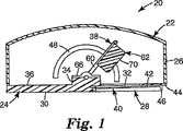
図1は、基部24及び上部カバー構造26を包含するハウジング22を有する、適用装置20の断面図である。基部24は、一般に矩形の形状であり、その底面30上に位置する窪み28を有する。一般に円形の開口部32は、基部24の窪み28の中に画定される。貼付剤加速又は貼付剤アプリケータアセンブリ38を保持するため、隆起部分34が基部24の上面36上に形成される。
FIG. 1 is a cross-sectional view of an
適用装置20の取付け構造又は保持部分は、第1の保持具及び第2の保持具とも称される、基部24に接続された一対の保持具40によって形成される(図1では1つの保持具40のみが見えている)。保持具部材40は一般に細長く、それぞれ、窪み28の底面44にほぼ平行であってそれに面し、且つ基部24の底面30(即ち、肌当て面)から間隔を空けた実質的に平坦な上面42を有する。一対の保持部材40は、開口部32の両側に配置され、窪み28の一方の側で基部24に接続される。保持部材40は、一方の端部で開口部46を画定して、保持部材40と窪み28の底部分44との間に貼付剤を受け入れる。保持部材40の上面42は、非粘着面又は剥離面であってもよい。非粘着面又は剥離面は、例えば、上面42に塗布された非付着コーティング又は剥離コーティングによって達成することができる。非粘着コーティング又は剥離コーティングは、適用装置20の所望の用途にしたがって選択することができる。例えば、低表面エネルギーのシリコーン、フルオロポリマー、又はフルオロシリコーン剥離コーティングなどの剥離コーティングを、貼付剤適用装置20を使用して塗布される貼付剤と共に使用される接着剤に基づいて選択することができる。更なる実施形態では、品目の部分を適用装置に取り付けられた貼付剤から分離するため、ブレード又は他の切断手段を、取付け構造の一部として提供することができる。
The attachment structure or holding portion of the
上部カバー構造26は、基部24の周辺又はその付近で基部24に接続される。上部カバー構造26は、基部24上に適合するように形作られ、貼付剤加速アセンブリ38のための空間を提供するように選択された体積を画定する。いくつかの実施形態では、ハウジング22も、アプリケータ装置20によって最終的に展開するため、貼付剤(例えば、貼付剤のロール)を保存する空間を提供してもよい。スロット48は、上部カバー構造26の側部内に画定される。図1に示される実施形態では、スロット48は弓状の形状で、一般に半円に似ており、半円の開いた部分がハウジング22の基部24に向いている。
The
基部24及び上部カバー構造26は両方とも、ポリマー材料で形成することができる。
Both
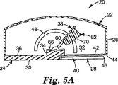
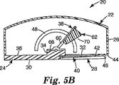
図2は、上部カバー部分26を省略して装置20の内部を示している、適用装置20の一部分の斜視図である。図2に示されるように、貼付剤加速アセンブリ38は、フレーム部材60、衝突体62、ハンドル64、ブラケット66、およびねじりばね68を包含する。ねじりばね68は、衝突体をハウジングに対して付勢する駆動部材として作用する。ブラケット66は、ハウジング22の基部24の隆起部分34に取り付けられ、フレーム部材60を旋回可能に保持する。場合によっては、ブラケット66は、例えば、基部がねじりばね68を配置できるような十分な厚さを有する場合、基部24に直接固着されてもよい。フレーム部材60は、矩形のループとして形成されたワイヤであることができる。衝突体62は、ブラケット66の反対側でフレーム部材60に取り付けられており、貼付剤と連動してそれを動かす(即ち、それを加速させる)貼付剤加速アセンブリ38の一部分であり、即ち装置の貼付剤に接する部分である。衝突体62は、例えば、適用される貼付剤の形状に基づいて、所望の適用の特性にしたがって構成された、貼付剤に接する表面70を有する。図1に示される実施形態では、貼付剤に接する表面70は、フレーム部材60にほぼ平行であってそれと整列されるように構成される。更に、装置20が完全に展開されたとき、その底面30とほぼ整列する。他の実施形態では、貼付剤に接する表面70は、フレーム部材60に対して、且つ装置20が完全に展開されたとき、その底面30に対して、別の角度であるように構成されてもよい。他のそのような角度は、代替の貼付剤に接する表面を有する装置の一部分を示す図5A、Bに示される。一実施形態では、貼付剤に接する表面70が、フレーム部材の面と4〜15°の角度を形成するように整列されるのが望ましいことがある。1つの態様では、貼付剤に接する表面70の角度は、貼付剤に接する表面70が貼付剤に接触するとき、保持部材40上の貼付剤架台の背面と整列するように選択されてもよい。衝突体62はポリマー材料で形成することができる。ハンドル64は、衝突体62から延び、衝突体62と一体に形成することができる。ハンドル64は、ハウジング22の上部カバー構造26内のスロット48を通って突出するように配置され、それにより、衝突体62の位置をハウジング22の外部から操作することが可能になる。図1は単に、貼付剤加速アセンブリ38を操作する1つの構成を表していることが理解されるべきである。例えば、スロットは、上部カバー部分26上に提供され、それによって、ハンドル64又は他のいかなる好適な作動突出部が、上部カバー部分26を通って突出することが可能になってもよい。更に、貼付剤加速アセンブリ38を操作する方法は、直接の機械的接続を用いなくてもよい。例えば、ハウジング22の外部のボタン又はノブを押して、又は回して貼付剤加速アセンブリ38を操作してもよいように、様々な連結又は歯車が提供されてもよい。更なる1つの実施例では、貼付剤加速アセンブリ38は、ハウジング22の外部のボタン又はノブによって電気的に制御される、モータ又はソレノイドによって動かされてもよい。
FIG. 2 is a perspective view of a portion of the
ねじりばね68は、貼付剤加速アセンブリ38のフレーム60をハウジング22の基部24に対して付勢する。ねじりばね68は、従来のコイルばねの鋼製ねじりばねであることができる。初期設定では、ねじりばね68は、フレーム60を、したがって衝突体62も、ハウジング22の基部24内の開口部32に向かって付勢する。実質的に電源が切られた状態では、衝突体は停止し、ハウジング22の基部24内の開口部32付近に配置される。ハンドル64を動かして、衝突体62を開口部から離し、ハウジング22の上部カバー構造26内のスロット48に沿ってハンドル64を動かすことによって画定することができる弓状の経路に沿って配置することにより、操作者は、ねじりばね68にポテンシャルエネルギーを保存することができる。ねじりばね68に保存されたエネルギーは、衝突体62を貼付剤に向かって加速させ、且つ衝突体62に接触している貼付剤を加速させるのに使用することができる。ねじりばね68に保存されたエネルギーの量は、開口部32から離れる、且つ弓状の経路に沿った衝突体62の変位量に大きく依存する。適切なねじりばね定数は、貼付剤加速アセンブリの質量、貼付剤の質量、貼付剤加速アセンブリがそれを通って移動する弧の長さ、及び表面と衝突するときの貼付剤の所望の速度など、多数のパラメータに依存する。ねじりばね定数は、多くの場合、約0.5N・mm/度超過、場合によっては約2.0N・mm/度超過になる。ねじりばね定数は、多くの場合、約5.0N・mm/度未満、場合によっては約4.0N・mm/度未満になる。衝突体62は、手動で、あるいはいくつかの実施形態では、ハウジング22の上部カバー構造26内のスロット48に沿って、ハンドル64に係合しそれを一時的に固定する保持手段(図示なし)を用いて、弓状の経路に沿って様々な地点で保持することができる。更なる実施形態では、弓状の経路に沿った衝突体62の変位の特定の度合に関連付けられた力のレベルを示すため、境界又は他の指標(例えば、力読出し表示部)を提供することができる。
The
貼付剤加速アセンブリの角移動の範囲は、多くの場合、約170°未満、場合によっては約110°未満になる。貼付剤加速アセンブリの角移動の範囲は、多くの場合、約10°超過、場合によっては約60°超過になる。貼付剤加速アセンブリの質量は、多くの場合、約1グラム超過、場合によっては約5グラム超過になる。貼付剤加速アセンブリの質量は、多くの場合、約100グラム未満、場合によっては約30グラム未満になる。 The range of angular movement of the patch acceleration assembly is often less than about 170 ° and in some cases less than about 110 °. The range of angular movement of the patch acceleration assembly is often greater than about 10 ° and in some cases greater than about 60 °. The mass of the patch acceleration assembly is often greater than about 1 gram and in some cases greater than about 5 grams. The mass of the patch acceleration assembly is often less than about 100 grams and in some cases less than about 30 grams.
図3は、アプリケータ装置20に取り付けられた貼付剤72(例えば、マイクロニードルアレイ74を支える貼付剤72)の斜視図である。貼付剤72は、保持具部材40とハウジング22の基部24内の窪み28の底部分44との間に配置される。マイクロニードルアレイ74は、ハウジング22の基部24内の開口部32から離れる方向に向いている。貼付剤72は、貼付剤適用装置20から離れる方向に向いている表面上のマイクロニードルアレイ74を取り囲む接着剤を有してもよく、保持具部材40の上面42に接触するが、一般に、上面42の剥離特性のため、保持具部材40にしっかりとは接着されない。図3に示されるように、完全に取り付けられた位置では、貼付剤72上で支えられたマイクロニードルアレイは、一般に、ハウジング22の基部24内の開口部32に対して整列される(開口部32は図3には見られない)。
FIG. 3 is a perspective view of a patch 72 (for example, a
保持具部材40は切欠部分76を有し、それが、一般に、ハウジング22の基部24の窪み28の底部分44上にある開口部32と整列された、拡大された部分的に円形の開放領域を提供する。切欠部分76によって画定されたより広い開放領域により、展開中に必要な貼付剤72の変形量を低減し、貼付剤72を適用装置20上の取付け位置から目標位置に移動することによって、貼付剤の適用が容易になる。そのような切欠部分76は任意であり、例えば、貼付剤がほぼ矩形の形状を有する場合、不要であってもよい。
The
図4は、適用装置20上に取り付けられた貼付剤72及びカバー82を有する、マイクロニードルアレイカートリッジ80の部分断面図である。適用装置20上の貼付剤72の取付けは、次の工程を包含する。カートリッジ80は、保持具部材40上に部分的に滑動される。次に、カートリッジ80は、保持具部材40に沿って更に滑動され、同時に、貼付剤72が適用装置20上に完全に取り付けられるまで、カバー82を貼付剤72から分離する(例えば、マイクロニードルアレイ74が、窪み28の底部分44内に画定された開口部32と整列するように)。カバー82は、貼付剤72から除去され(即ち、それから分離され)て、マイクロニードルを展開する前に、マイクロニードルアレイ74のカバーを外し、露出させる。
FIG. 4 is a partial cross-sectional view of a
図3及び4に示される貼付剤取付け構造は一例として提供され、限定するものではないことが認識されるべきである。更なる実施形態では、貼付剤をアプリケータ装置20上に取り付ける他の手段を使用することができ、取付け構造の設計は、一般に、アプリケータ装置20の他の構成要素の設計とは別個である。例えば、更なる実施形態では、1以上の貼付剤を適用の前にハウジング22内部に保存し、次に目標部位に適用するために分配することができる。貼付剤72のマイクロニードルアレイ74は、次のように展開することができる。操作者は、ハンドル64を使用して貼付剤加速アセンブリ38を「装填」又は「通電」して、衝突体62及びフレーム60を弓状の経路に沿って移動することにより、ねじりばね68のポテンシャルエネルギーを保存する。操作者は、貼付剤72が装置20に取り付けられる前又は後のいずれかに、貼付剤加速アセンブリ38を「装填」することができる。ねじりばね68に保存されるエネルギーの量は、所望の貼付剤適用部位の特性に基づいて選択することができ、異なる目標部位に対して変わってもよく、又は異なる貼付剤に対して変わってもよい。異なる量のエネルギーをねじりばね68に保存することにより、貼付剤加速アセンブリ38によって移動される貼付剤の加速度を調節することが可能になる。
It should be appreciated that the patch attachment structure shown in FIGS. 3 and 4 is provided by way of example and not limitation. In further embodiments, other means of attaching the patch onto the
適用装置20は、また、適用面に対して配置され、開口部32は、貼付剤を送達する目標部位に対して配置される。患者の皮膚上のマイクロニードル貼付剤を適用するのに適した部位は変化し、操作者は、アプリケータ装置20の適切な位置及び配向を選択しなければならない。貼付剤加速アセンブリ38が通電されるとき、貼付剤72はアプリケータ装置20に完全に取り付けられ、装置20は目標位置に対して配置され、次に、操作者はねじりばね68に保存されたエネルギーを解放することによって衝突体62を作動し、それが、衝突体62を貼付剤72に向かって、ハウジング22内のスロット48によって画定される弓状の経路に対応することができる弓状の経路に沿って移動する。衝突体62の貼付剤に接する表面70は、次に、貼付剤72に接触して、貼付剤72にエネルギーを伝達し、それを目標部位に向かって加速させる。保存されたエネルギーの解放は、ボタンを押すかノブを回してラッチ又は他の係止機構を解放し、それによって貼付剤加速アセンブリ38が貼付剤72を目標部位に向かって加速させることを可能にするなど、あらゆるの適切な手段によって行われてもよい。図示されるように、スロット48によって画定された弓状の経路は、円形の一部分(又は弧)である。他の実施形態では、衝突体は、あらゆるタイプの弓状の(即ち、湾曲した)経路に沿って動いてもよいことが理解されるべきである。更に、経路は実質的に弓状であってもよく、即ち、主に湾曲しているが、湾曲していない経路の小さな部分があってもよい。
The
一実施形態(図示なし)では、貼付剤は、直接固着されるか、別の方法で貼付剤加速アセンブリによって解放可能に保持されてもよい。例えば、貼付剤は、磁力によって衝突体に解放可能に保持されてもよい。衝突体は磁石を含んでもよく、貼付剤は、磁力で引き付けることができる金属を含んでもよい。衝突体は、例えば、永久磁石又は電磁石であってもよく、貼付剤の裏材は、磁力で引き付けることができる金属を含んでもよい。例えば、第一鉄ホイルの薄層が貼付剤の裏材に組み込まれてもよい。そのような磁力により、貼付剤が皮膚に接触するまで、貼付剤が衝突体に保持されるようにすることができる。その結果、貼付剤と皮膚の間の接着は、貼付剤加速アセンブリが、したがってアプリケータが貼付剤から除去されることができると同時に、貼付剤が皮膚の上で適所に残ることができるのに十分であり得る。貼付剤と皮膚の間の接着力は、典型的には、貼付剤と衝突体の間の磁力よりも大きい。場合によっては、貼付剤と皮膚の間の接着力は、貼付剤と衝突体の間の磁力の約2倍程度よりも大きくてもよい。適切な量の磁力は、容易に決定されてもよく、貼付剤と皮膚の間の接着力の大きさ、適用装置の設計、及び、貼付剤が皮膚に適用された後の貼付剤からのアプリケータの除去方法など、多数の要因に依存する。別の方法として、貼付剤は磁石を組み込んでもよく、衝突体は、鋼製の板ばねなどの磁性材料で作ることができる。解放可能な磁気取付け具は、前述及び後述の実施形態のいずれかのもの、並びに適用装置の他の実施形態、例えば、米国特許出願公開2002−0087182及び国際特許出願公開WO05/123173に記載のものに使用されてもよく、これらの開示を参照により本明細書に組み込む。 In one embodiment (not shown), the patch may be secured directly or otherwise releasably retained by the patch acceleration assembly. For example, the patch may be releasably held on the collision body by magnetic force. The collision body may include a magnet, and the patch may include a metal that can be attracted by a magnetic force. The collision body may be, for example, a permanent magnet or an electromagnet, and the backing material of the patch may include a metal that can be attracted by a magnetic force. For example, a thin layer of ferrous foil may be incorporated into the backing of the patch. Such a magnetic force allows the patch to be held by the collision body until the patch contacts the skin. As a result, the adhesion between the patch and the skin is such that the patch acceleration assembly, and thus the applicator can be removed from the patch, while the patch can remain in place on the skin. May be sufficient. The adhesive force between the patch and the skin is typically greater than the magnetic force between the patch and the impactor. In some cases, the adhesive force between the patch and the skin may be greater than about twice the magnetic force between the patch and the impactor. The appropriate amount of magnetic force may be easily determined, the magnitude of the adhesive force between the patch and the skin, the design of the application device, and the application from the patch after the patch has been applied to the skin. Depends on a number of factors, such as the removal method. Alternatively, the patch may incorporate a magnet and the impactor can be made of a magnetic material such as a steel leaf spring. The releasable magnetic fixture may be any of the embodiments described above and below, as well as other embodiments of the applicator, such as those described in US Patent Application Publication No. 2002-0087182 and International Patent Application Publication No. WO 05/123173. Which disclosures are incorporated herein by reference.
弱い接着剤接合、スナップ嵌め機構、又はフック・ループ式取付けなどの他の解放可能な取付けもまた、貼付剤を衝突体に接続するのに適していることがある。更に別の実施形態では、貼付剤は、保持機構の一部分に解放可能に取り付けられてもよい。例えば、衝突体は、その可動端部に開口部又は穴を有する板ばねなど、細長い駆動部材であってもよい。貼付剤は、板ばねの開口部又は穴を通って位置し、保持機構によって把持することができる、その背面から延びるスタブ又は他の突出部を有してもよい。板ばねは、その結果、貼付剤と保持機構の間で固定されるので、曲げられた位置でも適所で保持される。貼付剤のその取付け部から保持機構への解放、及び板ばねのその起上位置からの解放は、したがって、トリガーを起動させることによって同時に生じる。一実施形態では、単回使用の使い捨てユニットが、既に起動位置にある貼付剤加速アセンブリ38と共に提供されてもよいので、装置は、ボタンを押すことによって配置され発射されてもよい。
Other releasable attachments such as weak adhesive joints, snap-fit mechanisms, or hook and loop attachments may also be suitable for connecting the patch to the impactor. In yet another embodiment, the patch may be releasably attached to a portion of the retention mechanism. For example, the collision body may be an elongated drive member such as a leaf spring having an opening or a hole at the movable end thereof. The patch may have a stub or other protrusion that extends from its back surface that can be positioned through the opening or hole in the leaf spring and gripped by the retention mechanism. As a result, the leaf spring is fixed between the patch and the holding mechanism, so that it is held in place even in a bent position. Release of the patch from its attachment to the holding mechanism and release of the leaf spring from its raised position therefore occur simultaneously by activating the trigger. In one embodiment, a single use disposable unit may be provided with the
貼付剤72は、衝突体62がその弓状の経路に沿って移動すると、貼付剤72が移動して衝突体62と接触するときなど、少なくとも部分的に弓状の経路に沿って目標部位に向かって移動することができる。貼付剤72はまた、衝突体62が瞬間的に貼付剤72に接触し、その運動エネルギーを貼付剤72に伝達する(それは次に、衝突体62の弓状の経路とは異なるほぼ直線の経路に沿って移動する)場合など、衝突体62に接触した後、目標部位に向かって直線状に動くことができる。展開された貼付剤72は、分子を送達するため、所望のように目標部位に付着することができる。
The
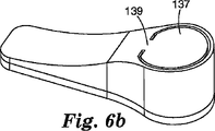
図6Aは、基部124及び上部カバー構造126を包含するハウジング122を有する、適用装置120の別の実施形態の斜視図である。装置は細長い形状であり、第1の先細の端部127及び第2の端部129を有する。第2の端部129は、タブ133を有する頂部の可剥性封止部131と、タブ135を有する底部の可剥性封止部132とによって封止された頂部および底部を有する(タブ135のみが図6Aに見られる)。図6Bは、可剥性封止部131、132が除去された後の適用装置を示す。トリガー137は、ハウジング122の上面に一体に形成される。トリガーは、単一の取付け点139でハウジングの上面に接続されるので、トリガーが、図6Dに示されるように親指又は指の圧力によって下向きに変形することが可能になる。
FIG. 6A is a perspective view of another embodiment of an
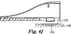
図6Cは、衝突体170に取り付けられた貼付剤172を示す装置の断面図である。衝突体170は、ハウジング122に取り付けられた固定端部167から可動端部169まで延びる長さを有する駆動部材166と一体に形成される。駆動部材166はその長さ部に沿って屈曲可能である。ラッチの形態の保持機構は、ハウジング122に取り付けられたフック125を使用する。フック125は、駆動部材166の可動端部169にあるスロット171と係合して、駆動部材166の可動端部169をハウジング122の肌当て面124から離して保持する。駆動部材は、いずれかの細長い屈曲可能な部材、例えば板ばねなどであってもよい。使用中、図6Cに示されるような装置は、皮膚表面(図示なし)などの目標表面に対して定置される。図6Dに示されるように、トリガー137を押し下げることにより、フック125が旋回し、その結果、駆動部材166の可動端部169が解放され、駆動部材166が貼付剤172を肌当て面124に向かって付勢することが可能になる。図6Eは、完全に展開され、貼付剤172を肌当て面124を越えて推進させている駆動部材166を示し、その結果、貼付剤は皮膚表面(図示なし)に押し付けられている。図6Fは、皮膚表面181から除去された装置120を示し、貼付剤172は、マイクロニードルアレイ174と共に皮膚表面181上の適所に残っている。図示されるように、衝突体170は、板ばねの巻かれた端部として示されており、これによって、(板ばねの可動端部169にあるスロット171を介して)保持機構を提供する従来手段が可能になると共に、別個の貼付剤に接する且つそれを保持する表面も提供される。しかしながら、駆動部材166の可動端部169には、巻かれた端部を有さない平坦な板ばねなど、いずれかの様々な適切な形状を使用してもよい。
FIG. 6C is a cross-sectional view of the apparatus showing the
図7Aは、基部224及び上部カバー構造226を包含するハウジング222を有する、適用装置220の別の実施形態の上面斜視図である。トリガー237は上部カバー構造226から延びる。図7Bは、ハンドル249を示し、図3に示した貼付剤保持構造に類似の、マイクロニードルアレイ274を備えたマイクロニードル貼付剤272を保持する保持具240を有する、適用装置220の下面斜視図である。図7Cは、ハウジング222に取り付けられた固定端部267から可動端部269まで延びる長さを有する、駆動部材266と一体に形成された衝突体270を示す断面図である。駆動部材266はその長さ部に沿って屈曲可能である。ラッチの形態の保持機構は、ハウジング222に取り付けられたフック225を使用する。フック225は、駆動部材266の可動端部269にあるスロット271と係合して、駆動部材266の可動端部269をハウジング222の肌当て面224から離して保持する。持上げ機構251は高い位置で示される。持上げ機構251は、ハンドル249(アプリケータの背面に破線で示される)に動作可能に接続され、やはり、駆動部材266を、駆動部材266が持ち上げられフック225に締結されている、図7Cに示されるような位置に持ち上げることができるように構成される。使用中、図7Cに示されるような装置は、皮膚表面(図示なし)などの目標表面に対して定置される。駆動部材266が、保持機構によって適所に係止された後、ハンドル249が解放され、それによって、持上げ機構251が図7Dに示されるような下に下がった位置まで解放されてもよい。トリガー237は、図7Dに示されるように横方向に押されてもよいので、駆動部材266の可動端部269は解放され、駆動部材266が、衝突体270を貼付剤272及び肌当て面224に向かって付勢することが可能になる。図7Dに示されるように、衝突体270は、貼付剤272を保持具240から肌当て面224を越えるところまで駆動するので、貼付剤は皮膚表面(図示なし)に押し付けられる。図7Eは、マイクロニードルアレイ274と共に貼付剤272を皮膚表面281上の適所に残して、皮膚表面281から除去された装置220を示す。
FIG. 7A is a top perspective view of another embodiment of an
適用装置220は、次の方法で複数の貼付剤を貼付するのに使用されてもよい。貼付剤を貼付した後、ハンドル249は持ち上げられて、それによって持上げ機構251及びしたがって駆動部材266が、図7Cに示されるような高い位置まで持ち上げられてもよく、トリガー237は、適所まで押し戻されて、駆動部材266を高い位置で係止してもよい。トリガー237は、手動で適所に動かされて、駆動部材266を係止してもよい。別の方法として、トリガー237は、それを係止位置に向かって付勢するばね(図示なし)によって、又は、駆動部材266がハンドルによって持ち上げられるとトリガー237を係止位置に移動する、ハンドル249に接続された機構(図示なし)によって、適所に動かされて駆動部材266を係止してもよい。あらゆる他の好適なトリガー及び再起上機構が使用されてもよい。別の貼付剤が次に、保持機構に装填され、上述のように適用されてもよい。
The
本発明のアプリケータ装置は、多数の利益及び利点を提供してもよい。ハウジングは、パーソナルコンピュータのマウスにほぼ似せて形作られてもよい。この形状は、例えば銃の形状をした適用装置又は他のドラッグ・デリバリー用品よりも患者を怖がらせない。ハウジングはまた、貼付剤加速アセンブリを保護し、任意に適用前の貼付剤の保存空間を提供する、適切な内容量を提供する。貼付剤の取付けは、迅速且つ容易に達成されてもよく、これは集団接種及び他の用途に有用である。しかしながら、あらゆる好適なハウジング形状が使用されてもよいことが理解されるべきである。例えば、ハウジングは、いくつかの実施形態では、円形、正方形、又は矩形の断面を有してもよく、特定の実施形態では、多面体であってもよい(即ち、ハウジングは平面によって形成される体積を画定してもよい)。いくつかの実施形態では、ハウジングは、1以上の矩形面を有する多面体、即ち矩形多面体であってもよい。いくつかの実施形態では、ハウジングは、側面が連続的に湾曲した、平坦な又は平面の基部を有してもよい。必須ではないが、貼付剤加速アセンブリは、(ハンドルを除いて)ハウジング内に完全に収容されることが好ましい。それに加えて、ねじりばね又は板ばねにより、適用装置を用いて貼付剤を適用するのに使用される力の単純で有効な調節が可能になり、適用装置を、様々な状況で使用し、様々な所望の貼付剤部位に貼付剤を適用することが可能になる。本発明の適用装置を使用してマイクロニードルアレイを適用する方法は、マイクロニードルアレイをマイクロニードルアレイアプリケーション装置に取り付ける工程と、マイクロニードルアレイを目標部位に向かって実質的に弓状の経路に沿って動かす工程とを含む。アレイは、例えば、上述したように、装置内の衝突体に固着されてもよい。衝突体を解放することにより、アレイが、実質的に弓状の経路に沿って目標部位に向かって移動することが可能になる。 The applicator device of the present invention may provide a number of benefits and advantages. The housing may be shaped substantially like a personal computer mouse. This shape does not scare the patient more than an application device or other drug delivery article, for example in the form of a gun. The housing also provides a suitable internal volume that protects the patch acceleration assembly and optionally provides a storage space for the patch prior to application. Patch application may be accomplished quickly and easily, which is useful for mass inoculation and other applications. However, it should be understood that any suitable housing shape may be used. For example, the housing may have a circular, square, or rectangular cross-section in some embodiments, and in certain embodiments may be a polyhedron (ie, the volume is defined by a flat surface). May be defined). In some embodiments, the housing may be a polyhedron having one or more rectangular surfaces, ie, a rectangular polyhedron. In some embodiments, the housing may have a flat or planar base that is continuously curved on the sides. Although not required, it is preferred that the patch acceleration assembly be fully contained within the housing (except for the handle). In addition, torsion springs or leaf springs allow a simple and effective adjustment of the force used to apply the patch using the application device, which can be used in various situations, The patch can be applied to any desired patch site. A method of applying a microneedle array using an applicator device of the present invention includes attaching the microneedle array to a microneedle array application device, and attaching the microneedle array to a target site along a substantially arcuate path. And moving the process. The array may be secured to an impactor in the device, for example, as described above. Release of the impactor allows the array to move toward the target site along a substantially arcuate path.
別の方法として、本発明の適用装置を使用してマイクロニードルアレイを適用する方法は、マイクロニードルアレイをマイクロニードルアレイ適用装置に取り付ける工程と、衝突体を実質的に弓状の経路に沿って移動して、マイクロニードルアレイを目標部位と接触させる工程とを含む。例えば、アレイは、図3に示されるような、衝突体とは別個の保持具を使用して、適用装置内に取り付けられてもよく、衝突体は、装填位置(即ち、保存されたエネルギーを含むところ)に配置され、次に弓状の経路に沿って移動するように解放されてもよい。衝突体は、次に、マイクロニードルアレイ(又はマイクロニードルアレイを保持する貼付剤)に接触し、マイクロニードルアレイを目標部位と接触させる。 Alternatively, a method of applying a microneedle array using the applicator of the present invention includes attaching the microneedle array to the microneedle array applicator and passing the impactor along a substantially arcuate path. Moving to bring the microneedle array into contact with the target site. For example, the array may be mounted in the application device using a holder that is separate from the impactor, as shown in FIG. 3, and the impactor has a loading position (ie, stored energy). And then released to move along an arcuate path. The colliding body then contacts the microneedle array (or the patch that holds the microneedle array), bringing the microneedle array into contact with the target site.
更に別の代替例では、本発明の適用装置を使用してマイクロニードルアレイを適用する方法は、マイクロニードル貼付剤を目標部位上に、又はそれに隣接して配置する工程を含む。本発明の適用装置は、マイクロニードルアレイと整列され、衝突体がマイクロニードルアレイを目標部位に押し込むように起動されてもよい。マイクロニードル貼付剤は、2005年6月24日出願の米国特許出願公開第60/693,901号に記載されているような折り畳み式の貼付剤を使用するなど、いずれかの好適な手段によって適用装置と接触する前に、皮膚表面上で適所に保持されてもよく、この開示を参照により本明細書に組み込む。 In yet another alternative, a method of applying a microneedle array using the application device of the present invention includes placing a microneedle patch on or adjacent to a target site. The application apparatus of the present invention may be aligned with the microneedle array and activated so that the impactor pushes the microneedle array into the target site. The microneedle patch is applied by any suitable means such as using a foldable patch as described in US Patent Application Publication No. 60 / 693,901 filed June 24, 2005. Prior to contacting the device, it may be held in place on the skin surface, the disclosure of which is incorporated herein by reference.
本発明の適用装置を使用してマイクロニードルアレイを適用する方法は、マイクロニードルアレイを、マイクロニードルを皮膚に突き通すのに有効な所望の速度に到達させる工程を伴う。所望の速度は、好ましくは、下にある神経組織の刺激を制限する、又は防ぐように制御される。皮膚に衝突する際にマイクロニードルアレイによって達成される最大速度は、多くの場合、毎分20メートル(m/s)以下、場合によっては15m/s以下、恐らくは10m/s以下である。場合によっては、最大速度は8m/s以下である。別の場合では、皮膚に衝突する際にマイクロニードルアレイによって達成される最小速度は、多くの場合、2m/s以上、場合によっては4m/s以上、恐らくは6m/s以上である。 The method of applying a microneedle array using the application device of the present invention involves causing the microneedle array to reach a desired velocity effective to penetrate the microneedle through the skin. The desired rate is preferably controlled to limit or prevent stimulation of the underlying neural tissue. The maximum velocity achieved by the microneedle array upon impacting the skin is often 20 meters per minute (m / s) or less, sometimes 15 m / s or less, and possibly 10 m / s or less. In some cases, the maximum speed is 8 m / s or less. In other cases, the minimum velocity achieved by the microneedle array upon impacting the skin is often 2 m / s or higher, in some cases 4 m / s or higher, and possibly 6 m / s or higher.
マイクロニードルアレイを皮膚内に駆動する装置の部分の質量は、好ましくは、不必要な不快感を患者に与えることを回避するのに十分に軽い。場合によっては、衝突体の質量は、約6グラム未満、場合によっては約4グラム未満、恐らくは約2グラム未満である。衝突体の質量は、典型的には、約0.4グラム超過、場合によっては約0.8グラム超過、恐らくは約1.2グラム超過である。図6Cに示されるような、衝突体が駆動部材と一体に形成された実施形態において、衝突体の質量を決定するため、衝突体は、一般に、マイクロニードルアレイの上方及び後方の部分を包含するが、駆動部材の可動端部から離れて、且つ駆動部材の固定端部に向かって延びる駆動部材の部分を包含しないものと見なされる。 The mass of the portion of the device that drives the microneedle array into the skin is preferably light enough to avoid imparting unnecessary discomfort to the patient. In some cases, the mass of the impactor is less than about 6 grams, in some cases less than about 4 grams, and possibly less than about 2 grams. The impactor mass is typically greater than about 0.4 grams, in some cases greater than about 0.8 grams, and perhaps greater than about 1.2 grams. In an embodiment where the impactor is integrally formed with the drive member, as shown in FIG. 6C, the impactor generally includes the upper and rear portions of the microneedle array to determine the mass of the impactor. Are not considered to include portions of the drive member that extend away from the movable end of the drive member and toward the fixed end of the drive member.
一実施形態では、皮膚との衝突時にマイクロニードルアレイによって達成される速度は、約4m/s〜8m/sになり、衝突体の質量は、約0.4グラム〜約2グラムになる。板ばねをマイクロニードル貼付剤に直接結合された駆動部材として使用することにより、比較的低い質量の衝突体と組み合わせて、装置が皮膚との衝突時に所望の速度を得ることが可能になるので、特に有利なことがある。 In one embodiment, the velocity achieved by the microneedle array upon impact with the skin will be about 4 m / s to 8 m / s and the impactor mass will be about 0.4 grams to about 2 grams. By using the leaf spring as a drive member directly coupled to the microneedle patch, it becomes possible to obtain a desired speed when the device collides with the skin in combination with a relatively low mass impactor. It can be particularly advantageous.
そのような高速低質量の送達は、多数のマイクロニードルを有するマイクロニードルアレイを適用するとき、特に有利なことがある。理論によって束縛されることを望まないが、多数のマイクロニードルを有するアレイのモーメントは、非常に低く、依然として許容可能なマイクロニードルの角質層への浸透を達成することができるが、これは、各マイクロニードルが非常に小さな質量を有し、比較的短い距離しか皮膚に浸透しないためである。特に、100個を超える、多くの場合、500個を超える、場合によっては1000個を超えるマイクロニードルを有するマイクロニードルアレイの挿入は、上述の装置を使用して実行した場合に特に有効であり得る。 Such fast, low mass delivery may be particularly advantageous when applying microneedle arrays having a large number of microneedles. Although not wishing to be bound by theory, the moment of the array with a large number of microneedles is very low and can still achieve acceptable microneedle penetration into the stratum corneum, This is because microneedles have a very small mass and penetrate only a relatively short distance into the skin. In particular, the insertion of a microneedle array having more than 100, often more than 500, and possibly more than 1000 microneedles can be particularly effective when performed using the above-described apparatus. .
マイクロニードルの浸透の深さは、マイクロニードル及びマイクロニードルアレイ両方のサイズ及び設計などの多数の要因によって、並びにアレイが皮膚に衝突する速度によって変わる。一実施形態では、マイクロニードルは、40μm超過、場合によっては80μm超過、場合によっては100μm超過の深さまで浸透する。一実施形態では、マイクロニードルは、300μm未満、場合によっては200μm未満、場合によっては150μm未満の深さまで浸透する。別の実施形態では、マイクロニードルは、マイクロニードルの全高の20%超過、場合によっては40%超過、場合によっては50%超過の深さまで浸透する。別の実施形態では、マイクロニードルは、マイクロニードルの全高の約80%未満、場合によっては60%未満、場合によっては50%未満の深さまで浸透する。 The depth of penetration of the microneedles depends on a number of factors such as the size and design of both the microneedles and the microneedle array and the speed at which the array impacts the skin. In one embodiment, the microneedles penetrate to a depth of more than 40 μm, possibly more than 80 μm, and sometimes more than 100 μm. In one embodiment, the microneedles penetrate to a depth of less than 300 μm, in some cases less than 200 μm, and in some cases less than 150 μm. In another embodiment, the microneedles penetrate to a depth of more than 20%, sometimes more than 40%, and sometimes more than 50% of the total height of the microneedle. In another embodiment, the microneedles penetrate to a depth of less than about 80%, sometimes less than 60%, and sometimes less than 50% of the total microneedle height.
マイクロニードルは、典型的には高さ500ミクロン未満、場合によっては高さ300ミクロン未満である。マイクロニードルは、典型的には高さ20ミクロン超過、多くの場合、高さ50ミクロン超過、場合によっては高さミクロン超過である。マイクロニードルの高さは、平坦な基部又は基板から突出する距離として測定されてもよい。一実施形態では、マイクロニードルは、不均一な基板から突出してもよく、例えば、各マイクロニードルは、それ自体が平面の基板から突出している平坦な基部又は台座上に載置されてもよい。 Microneedles are typically less than 500 microns in height and in some cases less than 300 microns in height. Microneedles are typically over 20 microns in height, often over 50 microns in height, and in some cases over micron in height. The height of the microneedles may be measured as the distance protruding from the flat base or substrate. In one embodiment, the microneedles may protrude from a non-uniform substrate, for example, each microneedle may rest on a flat base or pedestal that itself protrudes from a planar substrate.
皮膚の位置及び異なる個人の付属肢のサイズにばらつきがあることにより、任意に、適用装置は、適用装置に対する皮膚の位置及び付属肢のサイズのばらつきに適応するのに十分な距離にわたって、マイクロニードルアレイが所望の最小速度以上の速度で移動するように設計される。例えば、適用装置内のマイクロニードルアレイは、1ミリメートル以上の距離にわたって、最小速度以上で移動してもよい。いくつかの実施形態では、マイクロニードルアレイは、5ミリメートル以上の距離にわたって、最小速度以上で移動してもよい。 Due to variations in skin location and different individual appendage sizes, the application device optionally allows the microneedles to span a distance sufficient to accommodate variations in skin position and appendage size relative to the application device. The array is designed to move at a speed above the desired minimum speed. For example, the microneedle array in the application device may move above a minimum speed over a distance of 1 millimeter or more. In some embodiments, the microneedle array may move at a minimum speed or more over a distance of 5 millimeters or more.
本発明の様々な実施形態において有用なマイクロニードルアレイは、以下の特許及び特許出願に記載されているような様々な構成のいずれかを含んでもよく、それらの開示を参照により本明細書に組み込む。マイクロニードルアレイの一実施形態は、米国特許出願公開2003/0045837に開示の構造を含む。上述の特許出願に開示されるミクロ構造は、各マイクロニードルの外側表面に形成された少なくとも1つのチャネルを包含する、先細の構造を有するマイクロニードルの形態である。マイクロニードルは、一方向に細長い基部を有してもよい。細長い基部を有するマイクロニードルのチャネルは、細長い基部の端部の1つからマイクロニードルの先端に向かって延びてもよい。マイクロニードルの側部に沿って形成されたチャネルは、任意に、マイクロニードルの先端の手前で終端してもよい。マイクロニードルアレイはまた、マイクロニードルアレイが上に配置される基板の表面上に形成された導管構造を包含してもよい。マイクロニードルのチャネルは、導管構造と流体連通していてもよい。マイクロニードルアレイの別の実施形態は、頂部を切断した円錐形の先細形状及び制御されたアスペクト比を有するマイクロニードルを記載している、米国特許出願公開2005/0261631に開示の構造を含んでもよい。マイクロニードルの更に別の実施形態は、皮膚に孔をあけるためのブレード状のミクロ突出部を記載している、米国特許第6,091,975号(ダドナ(Daddona)ら)に開示されている構造を含む。マイクロニードル装置の更に別の実施形態は、中空の中央チャネルを有する先細構造を記載している、米国特許第6,313,612号(シャーマン(Sherman)ら)に開示されている構造を含む。マイクロアレイの更に別の実施形態は、マイクロニードルの先端の上面に少なくとも1つの長手方向のブレードを有する中空のマイクロニードルを記載している、米国特許第6,379,324号(ガートスタイン(Gartstein)ら)に開示されている構造を含む。 Microneedle arrays useful in various embodiments of the present invention may include any of a variety of configurations as described in the following patents and patent applications, the disclosures of which are incorporated herein by reference. . One embodiment of a microneedle array includes the structure disclosed in US Patent Application Publication 2003/0045837. The microstructure disclosed in the aforementioned patent application is in the form of a microneedle having a tapered structure that includes at least one channel formed in the outer surface of each microneedle. The microneedle may have an elongated base in one direction. A channel of a microneedle having an elongated base may extend from one of the ends of the elongated base toward the tip of the microneedle. The channel formed along the side of the microneedle may optionally terminate before the tip of the microneedle. The microneedle array may also include a conduit structure formed on the surface of the substrate on which the microneedle array is disposed. The channel of the microneedle may be in fluid communication with the conduit structure. Another embodiment of a microneedle array may include the structure disclosed in US Patent Application Publication No. 2005/0261631 describing a microneedle having a conical tapering shape with a truncated top and a controlled aspect ratio. . Yet another embodiment of the microneedle is disclosed in US Pat. No. 6,091,975 (Daddona et al.), Which describes a blade-like microprotrusion for piercing the skin. Includes structure. Yet another embodiment of a microneedle device includes the structure disclosed in US Pat. No. 6,313,612 (Sherman et al.) Describing a tapered structure having a hollow central channel. Yet another embodiment of the microarray describes US Pat. No. 6,379,324 (Gartstein), which describes a hollow microneedle having at least one longitudinal blade on the top surface of the microneedle tip. And the like.
本発明のマイクロニードルアレイ及びマイクロニードル貼付剤は、薬物(いずれかの1つ又は複数の治療薬を包含する)を、様々な経皮的送達において皮膚を通して、又は予防接種などの皮内若しくは局所治療のために皮膚まで送達するのに使用されてもよい。 The microneedle arrays and microneedle patches of the present invention can be used to deliver drugs (including any one or more therapeutic agents) through the skin in various transdermal delivery, or intradermal or topical, such as vaccinations. It may be used to deliver to the skin for treatment.
1つの態様では、分子量が大きな薬物は経皮的に送達されてもよい。薬物の分子量が増加すると、典型的には、支援されない経皮的送達が減少する。本発明のマイクロニードルアレイは、本来は受動的な経皮的送達によって送達することが困難な、大きな分子の送達に有用である。そのような大きな分子の例としては、タンパク質、ペプチド、ヌクレオチド配列、モノクローナル抗体、DNAワクチン、ヘパリンなどの多糖類、及びセフトリアキソンなどの抗生物質が挙げられる。 In one embodiment, a high molecular weight drug may be delivered transdermally. Increasing the molecular weight of the drug typically reduces unassisted transdermal delivery. The microneedle array of the present invention is useful for delivery of large molecules that are inherently difficult to deliver by passive transdermal delivery. Examples of such large molecules include proteins, peptides, nucleotide sequences, monoclonal antibodies, DNA vaccines, polysaccharides such as heparin, and antibiotics such as ceftriaxone.
別の態様では、本発明のマイクロニードルアレイ及びマイクロニードル貼付剤は、別の方法では受動的な経皮的送達によって送達するのが困難又は不可能な、小さな分子の経皮的送達を強化する、又は可能にするのに有用なことがある。そのような分子の例としては、塩の形態、ビスホスホネート、好ましくはアレンドロネートナトリウム又はパメドロネート(pamedronate)ナトリウムなどのイオン分子、受動的な経皮的送達に寄与しない物理化学的特性を有する分子が挙げられる。 In another aspect, the microneedle arrays and microneedle patches of the present invention enhance transdermal delivery of small molecules that are otherwise difficult or impossible to deliver by passive transdermal delivery. Or may be useful to enable. Examples of such molecules include salt forms, bisphosphonates, preferably ionic molecules such as sodium alendronate or pamedronate sodium, molecules with physicochemical properties that do not contribute to passive transdermal delivery. Can be mentioned.
別の態様では、本発明のマイクロニードルアレイ及びマイクロニードル貼付剤は、外皮治療、ワクチン送達などにおいて分子を皮膚に送達するのを強化するのに、或いはワクチン補助剤の免疫反応を強化するのに有用なことがある。 In another aspect, the microneedle array and microneedle patch of the present invention enhances the delivery of molecules to the skin, such as in skin treatment, vaccine delivery, or to enhance the immune response of vaccine adjuvants. Sometimes useful.
マイクロニードルアレイ及びマイクロニードル貼付剤は、適用部位に適用されそこから即座に除去される、即時の送達に使用されてもよく、或いは、数分から1週間程度までの範囲であってもよい長時間の間、適所に残されてもよい。1つの態様では、適用し即座に除去することによって得られるよりも十分な薬物の送達を可能にするため、長時間の送達は、1〜30分間であってもよい。別の態様では、長時間の送達は、薬物の持続放出を提供するため、4時間〜1週間であってもよい。 The microneedle array and microneedle patch may be used for immediate delivery, applied to the application site and immediately removed therefrom, or may be in the range of minutes to a week or so May be left in place. In one aspect, prolonged delivery may be from 1 to 30 minutes to allow sufficient drug delivery than obtained by application and immediate removal. In another aspect, prolonged delivery may be from 4 hours to 1 week to provide sustained release of the drug.
いくつかの代替実施形態を参照して本発明を記載してきたが、当業者であれば、本発明の趣旨及び範囲から逸脱することなく、形態及び詳細を変更してもよいことを認識するであろう。 Although the invention has been described with reference to several alternative embodiments, those skilled in the art will recognize that changes may be made in form and detail without departing from the spirit and scope of the invention. I will.
上記の図面は本発明のいくつかの実施形態を説明するが、考察において記載したように、他の実施形態もまた想到される。すべての場合において、本開示は、代表例によって本発明を表しており、限定を意味するものではない。多数の他の修正例及び実施形態が当業者によって考案でき、それらは本発明の原理の範囲及び趣旨の範囲内にあることが理解されるべきである。図面は縮尺通りに描かれていない場合がある。図面全体を通して、類似の部分を表すために類似の参照番号が使用されている。 While the above drawings illustrate some embodiments of the present invention, other embodiments are also contemplated, as described in the discussion. In all cases, this disclosure presents the invention by way of representation and is not meant to be limiting. It should be understood that many other modifications and embodiments can be devised by those skilled in the art and are within the scope and spirit of the principles of the present invention. The drawings may not be drawn to scale. Throughout the drawings, like reference numerals are used to denote like parts.
Claims (4)
目標部位に配置可能な開口部を画定する肌当て面を有するハウジングと、
前記マイクロニードルアレイに衝突して前記マイクロニードルアレイを前記目標部位に向かって加速させる衝突体と、を備え、
前記衝突体が、実質弓状の経路に沿って移動して、前記マイクロニードルアレイを前記目標部位に向かって移動させることができ、
前記衝突体を前記ハウジングに対して付勢する駆動部材を更に備え、
前記駆動部材が、前記ハウジングに取り付けられた固定端部から可動端部まで延びる長さ部分を有し、前記駆動部材が前記長さ部分に沿って屈曲可能であり、前記駆動部材の前記可動端部が、前記マイクロニードルアレイに接触して該マイクロニードルアレイを推進させることができるように構成され、前記駆動部材の前記可動端部が前記衝突体として作用する、適用装置。An application device for applying a microneedle array,
A housing having a skin contact surface that defines an opening that can be disposed at a target site;
A collision body that collides with the microneedle array and accelerates the microneedle array toward the target site,
The impactor may move along a substantially arcuate path to move the microneedle array toward the target site ;
A drive member for urging the collision body against the housing;
The drive member has a length portion extending from a fixed end portion attached to the housing to a movable end portion, the drive member is bendable along the length portion, and the movable end of the drive member An application device, wherein a portion is configured to contact the microneedle array to propel the microneedle array, and the movable end of the drive member acts as the collision body .
Applications Claiming Priority (5)
| Application Number | Priority Date | Filing Date | Title |
|---|---|---|---|
| US69444705P | 2005-06-27 | 2005-06-27 | |
| US60/694,447 | 2005-06-27 | ||
| US74629806P | 2006-05-03 | 2006-05-03 | |
| US60/746,298 | 2006-05-03 | ||
| PCT/US2006/024671 WO2007002521A2 (en) | 2005-06-27 | 2006-06-23 | Microneedle array applicator device |
Publications (3)
| Publication Number | Publication Date |
|---|---|
| JP2008543527A JP2008543527A (en) | 2008-12-04 |
| JP2008543527A5 JP2008543527A5 (en) | 2009-06-18 |
| JP5144510B2 true JP5144510B2 (en) | 2013-02-13 |
Family
ID=37054466
Family Applications (1)
| Application Number | Title | Priority Date | Filing Date |
|---|---|---|---|
| JP2008519435A Active JP5144510B2 (en) | 2005-06-27 | 2006-06-23 | Microneedle array application device |
Country Status (7)
| Country | Link |
|---|---|
| US (2) | US8784363B2 (en) |
| EP (2) | EP1901799B1 (en) |
| JP (1) | JP5144510B2 (en) |
| CN (1) | CN101208130B (en) |
| AU (1) | AU2006261898B2 (en) |
| CA (1) | CA2613111C (en) |
| WO (1) | WO2007002521A2 (en) |
Families Citing this family (97)
| Publication number | Priority date | Publication date | Assignee | Title |
|---|---|---|---|---|
| GB0402131D0 (en) | 2004-01-30 | 2004-03-03 | Isis Innovation | Delivery method |
| US8267889B2 (en) | 2004-11-18 | 2012-09-18 | 3M Innovative Properties Company | Low-profile microneedle array applicator |
| US10035008B2 (en) | 2005-04-07 | 2018-07-31 | 3M Innovative Properties Company | System and method for tool feedback sensing |
| JP2008543528A (en) | 2005-06-27 | 2008-12-04 | スリーエム イノベイティブ プロパティズ カンパニー | Microneedle cartridge assembly and application method |
| US9119945B2 (en) | 2006-04-20 | 2015-09-01 | 3M Innovative Properties Company | Device for applying a microneedle array |
| GB2448493B (en) | 2007-04-16 | 2009-10-14 | Dewan Fazlul Hoque Chowdhury | Microneedle transdermal delivery device |
| US8911749B2 (en) | 2007-04-16 | 2014-12-16 | Corium International, Inc. | Vaccine delivery via microneedle arrays |
| EP2146689B1 (en) | 2007-04-16 | 2020-08-12 | Corium, Inc. | Solvent-cast microneedle arrays containing active |
| CA2745339C (en) | 2007-12-24 | 2016-06-28 | The University Of Queensland | Coating method |
| WO2009097660A1 (en) | 2008-02-07 | 2009-08-13 | The University Of Queensland | Patch production |
| WO2009140735A1 (en) | 2008-05-23 | 2009-11-26 | The University Of Queensland | Analyte detection by microneedle patch with analyte selective reagents. |
| EP2355887B1 (en) | 2008-11-18 | 2017-08-02 | 3M Innovative Properties Company | Hollow microneedle array |
| EP2399643A4 (en) | 2009-02-23 | 2012-08-22 | Medrx Co Ltd | Applicator for microneedle array |
| US20120277629A1 (en) | 2011-04-29 | 2012-11-01 | Seventh Sense Biosystems, Inc. | Systems and methods for collection and/or manipulation of blood spots or other bodily fluids |
| WO2012018486A2 (en) | 2010-07-26 | 2012-02-09 | Seventh Sense Biosystems, Inc. | Rapid delivery and/or receiving of fluids |
| WO2010101620A2 (en) | 2009-03-02 | 2010-09-10 | Seventh Sense Biosystems, Inc. | Systems and methods for creating and using suction blisters or other pooled regions of fluid within the skin |
| EP3354312A1 (en) | 2009-07-31 | 2018-08-01 | 3M Innovative Properties Co. | Hollow microneedle arrays |
| JP5663792B2 (en) * | 2009-08-07 | 2015-02-04 | 株式会社 メドレックス | Kenzan microneedle applicator device |
| CN103096970B (en) | 2010-01-22 | 2016-10-26 | 株式会社医药处方 | The adhesion patch aid of skin patch is adhered to for micropin |
| WO2011094573A1 (en) | 2010-01-28 | 2011-08-04 | Seventh Sense Biosystems, Inc. | Monitoring or feedback systems and methods |
| GB201007207D0 (en) * | 2010-04-29 | 2010-06-16 | Univ Cork | Method |
| JP6327852B2 (en) | 2010-05-04 | 2018-05-23 | コリウム インターナショナル, インコーポレイテッド | Methods and devices for transdermal delivery of parathyroid hormone using microprojection arrays |
| ES2734560T3 (en) | 2010-05-04 | 2019-12-10 | Corium Int Inc | Microneedle applicators |
| WO2011163347A2 (en) | 2010-06-23 | 2011-12-29 | Seventh Sense Biosystems, Inc. | Sampling devices and methods involving relatively little pain |
| JP5562138B2 (en) | 2010-06-24 | 2014-07-30 | シスメックス株式会社 | Micropore forming device |
| WO2012006677A1 (en) * | 2010-07-14 | 2012-01-19 | The University Of Queensland | Patch applying apparatus |
| WO2012009613A1 (en) | 2010-07-16 | 2012-01-19 | Seventh Sense Biosystems, Inc. | Low-pressure environment for fluid transfer devices |
| WO2012021801A2 (en) | 2010-08-13 | 2012-02-16 | Seventh Sense Biosystems, Inc. | Systems and techniques for monitoring subjects |
| US20120089118A1 (en) * | 2010-10-08 | 2012-04-12 | A Nevada Corporation | Delivery of bisphosphonates by microinjection systems |
| WO2012064802A1 (en) | 2010-11-09 | 2012-05-18 | Seventh Sense Biosystems, Inc. | Systems and interfaces for blood sampling |
| US8795234B2 (en) | 2010-11-30 | 2014-08-05 | Becton, Dickinson And Company | Integrated spring-activated ballistic insertion for drug infusion device |
| US9950109B2 (en) | 2010-11-30 | 2018-04-24 | Becton, Dickinson And Company | Slide-activated angled inserter and cantilevered ballistic insertion for intradermal drug infusion |
| US8814831B2 (en) | 2010-11-30 | 2014-08-26 | Becton, Dickinson And Company | Ballistic microneedle infusion device |
| WO2012075375A1 (en) * | 2010-12-02 | 2012-06-07 | Lanco Biosciences, Inc. | Delivery of parathyroid hormones by microinjection systems |
| WO2012075209A1 (en) * | 2010-12-02 | 2012-06-07 | Lanco Biosciences, Inc. | Delivery of triptans by microinjection systems |
| US20120143119A1 (en) * | 2010-12-02 | 2012-06-07 | Lanco Biosciences, Inc. | Delivery of Serotonin Receptor Antagonists By Microinjection Systems |
| WO2012075339A1 (en) * | 2010-12-02 | 2012-06-07 | Lanco Biosciences, Inc. | Delivery of heparins by microinjection systems |
| AU2011349277A1 (en) | 2010-12-22 | 2013-06-27 | Valeritas, Inc. | Microneedle patch applicator |
| IT1403293B1 (en) | 2010-12-27 | 2013-10-17 | Fond Don Carlo Gnocchi Onlus | NEEDLE APPLIANCE FOR TRANSDERMIC DRUG ADMINISTRATION. |
| CN102727992A (en) * | 2011-03-31 | 2012-10-17 | 株式会社汉比特科技与创新 | Stamp type needle assembly |
| US20130158468A1 (en) | 2011-12-19 | 2013-06-20 | Seventh Sense Biosystems, Inc. | Delivering and/or receiving material with respect to a subject surface |
| WO2012149155A1 (en) | 2011-04-29 | 2012-11-01 | Seventh Sense Biosystems, Inc. | Systems and methods for collecting fluid from a subject |
| EP2701600B1 (en) | 2011-04-29 | 2016-06-08 | Seventh Sense Biosystems, Inc. | Delivering and/or receiving fluids |
| WO2013036602A1 (en) * | 2011-09-07 | 2013-03-14 | 3M Innovative Properties Company | Delivery system for hollow microneedle arrays |
| JP5921557B2 (en) * | 2011-09-16 | 2016-05-24 | 久光製薬株式会社 | applicator |
| NL2007461C2 (en) | 2011-09-23 | 2013-03-26 | Ambro B V | System for transporting fluid across or into a biological barrier, device and capsule as part of the system. |
| WO2013053022A1 (en) | 2011-10-12 | 2013-04-18 | The University Of Queensland | Delivery device |
| AU2012323392A1 (en) * | 2011-10-12 | 2014-04-24 | 3M Innovative Properties Company | Integrated microneedle array delivery system |
| JP6305924B2 (en) * | 2011-10-12 | 2018-04-04 | スリーエム イノベイティブ プロパティズ カンパニー | Integrated microneedle array delivery system |
| ES2788517T3 (en) * | 2012-12-21 | 2020-10-21 | Hisamitsu Pharmaceutical Co | Applicator |
| JP6865524B2 (en) | 2012-12-21 | 2021-04-28 | コリウム, インコーポレイテッド | Microarrays and usages for delivering therapeutic agents |
| KR102236575B1 (en) * | 2012-12-21 | 2021-04-05 | 쓰리엠 이노베이티브 프로퍼티즈 컴파니 | Adhesive assemblies and microneedle injection apparatuses comprising same |
| WO2014105458A1 (en) | 2012-12-27 | 2014-07-03 | 3M Innovative Properties Company | Article with hollow microneedles and method of making |
| US10245422B2 (en) | 2013-03-12 | 2019-04-02 | Corium International, Inc. | Microprojection applicators and methods of use |
| CA2903583C (en) | 2013-03-15 | 2021-12-28 | Corium International, Inc. | Microarray for delivery of therapeutic agent, methods of use, and methods of making |
| EP2968751B1 (en) | 2013-03-15 | 2022-11-30 | Corium, Inc. | Multiple impact microprojection applicators |
| CN105246458B (en) | 2013-03-15 | 2020-09-15 | 考里安公司 | Microarrays for therapeutic agent delivery and methods of use thereof |
| EP2968116A1 (en) | 2013-03-15 | 2016-01-20 | Corium International, Inc. | Microarray with polymer-free microstructures, methods of making, and methods of use |
| SG11201509722PA (en) | 2013-05-31 | 2015-12-30 | 3M Innovative Properties Co | Microneedle injection apparatus comprising a dual cover |
| US9682222B2 (en) * | 2013-05-31 | 2017-06-20 | 3M Innovative Properties Company | Microneedle injection apparatus comprising an inverted actuator |
| JP6494601B2 (en) | 2013-05-31 | 2019-04-03 | スリーエム イノベイティブ プロパティズ カンパニー | Microneedle injection and injection device and method of use thereof |
| WO2015017561A1 (en) | 2013-07-30 | 2015-02-05 | Zosano Pharma, Inc. | Low-profile microneedle patch applicator |
| JP6434521B2 (en) * | 2013-09-05 | 2018-12-05 | サノフィ−アベンティス・ドイチュラント・ゲゼルシャフト・ミット・ベシュレンクテル・ハフツング | Drive mechanism for needle insertion device |
| US10086183B2 (en) | 2013-11-05 | 2018-10-02 | Hisamitsu Pharmaceutical Co., Inc. | Applicator |
| JP6199702B2 (en) * | 2013-11-06 | 2017-09-20 | 久光製薬株式会社 | applicator |
| WO2015168219A1 (en) * | 2014-04-30 | 2015-11-05 | Kimberly-Clark World Wide, Inc. | Controller portion of transdermal drug delivery apparatus and methods |
| WO2016036866A1 (en) | 2014-09-04 | 2016-03-10 | Corium International, Inc. | Microstructure array, methods of making, and methods of use |
| US10292734B1 (en) | 2014-10-24 | 2019-05-21 | Verily Life Sciences Llc | Micro-structures with magnetic removal capability and optionally clear optical path |
| WO2016121499A1 (en) * | 2015-01-27 | 2016-08-04 | 凸版印刷株式会社 | Transdermal administration device |
| US11147954B2 (en) | 2015-02-02 | 2021-10-19 | Vaxxas Pty Limited | Microprojection array applicator and method |
| WO2017004067A1 (en) | 2015-06-29 | 2017-01-05 | Corium International, Inc. | Microarray for delivery of therapeutic agent, methods of use, and methods of making |
| USD776263S1 (en) | 2015-07-30 | 2017-01-10 | Becton, Dickinson And Company | Medical injector |
| USD767120S1 (en) | 2015-07-30 | 2016-09-20 | Becton, Dickinson And Company | Medical injector |
| USD794776S1 (en) | 2015-07-30 | 2017-08-15 | Becton, Dickinson And Company | Medical injector |
| USD776264S1 (en) | 2015-07-30 | 2017-01-10 | Becton, Dickinson And Company | Medical injector |
| USD774640S1 (en) | 2015-07-30 | 2016-12-20 | Becton, Dickinson And Company | Medical injector |
| USD776262S1 (en) | 2015-07-30 | 2017-01-10 | Becton, Dickinson And Company | Medical injector |
| USD776265S1 (en) | 2015-07-30 | 2017-01-10 | Becton, Dickinson And Company | Medical injector |
| CN108136165B (en) | 2015-09-02 | 2020-11-06 | 久光制药株式会社 | Applicator |
| US11103259B2 (en) | 2015-09-18 | 2021-08-31 | Vaxxas Pty Limited | Microprojection arrays with microprojections having large surface area profiles |
| EP3496681A4 (en) * | 2016-08-08 | 2020-07-22 | Avedro, Inc. | Systems and methods for cross-linking treatments of an eye |
| KR101746048B1 (en) * | 2016-09-13 | 2017-06-12 | 주식회사 라파스 | Microneedle patch applicator |
| ES2960937T3 (en) | 2017-03-31 | 2024-03-07 | Vaxxas Pty Ltd | Device and method for coating surfaces |
| US11175128B2 (en) | 2017-06-13 | 2021-11-16 | Vaxxas Pty Limited | Quality control of substrate coatings |
| MA49562A (en) | 2017-07-14 | 2020-05-20 | Amgen Inc | NEEDLE INSERTION-RETRACTION SYSTEM FEATURING A DOUBLE-TORSION SPRING SYSTEM |
| US11464957B2 (en) | 2017-08-04 | 2022-10-11 | Vaxxas Pty Limited | Compact high mechanical energy storage and low trigger force actuator for the delivery of microprojection array patches (MAP) |
| DE102017007485A1 (en) * | 2017-08-09 | 2019-02-14 | Lts Lohmann Therapie-Systeme Ag | Adapter system with frame, active ingredient pad and lid |
| US11642505B2 (en) | 2017-11-30 | 2023-05-09 | Hisamitsu Pharmaceutical Co., Inc. | Applicator, cartridge and application kit |
| US10786203B1 (en) * | 2018-01-30 | 2020-09-29 | Daniel M. Besser | Medical patch applicator device |
| WO2019166572A1 (en) | 2018-02-28 | 2019-09-06 | Pharming Intellectual Property B.V. | Pharmaceutical system for transdermal administration of a c1 -esterase inhibitor |
| DE102019001251A1 (en) * | 2019-02-21 | 2020-08-27 | Lts Lohmann Therapie-Systeme Ag | Microneedle plaster applicator |
| JP2023504540A (en) * | 2019-12-05 | 2023-02-03 | フォリカ,インコーポレーテッド | lancing device and penetration depth |
| US20210393201A1 (en) * | 2020-06-17 | 2021-12-23 | Biolinq, Inc. | Devices and Methods For Application Of Microneedle Arrays Using Radial And Axial Accelerations |
| US11389376B2 (en) | 2020-12-21 | 2022-07-19 | Mediccene Inc. | Wearable intravenous fluid delivery system |
| US11672965B2 (en) | 2021-09-28 | 2023-06-13 | Biolinq Incorporated | Microneedle enclosure and applicator device for microneedle array based continuous analyte monitoring device |
| US11877848B2 (en) | 2021-11-08 | 2024-01-23 | Satio, Inc. | Dermal patch for collecting a physiological sample |
| CN114081538B (en) * | 2021-11-12 | 2023-09-15 | 江西中医药大学 | Microneedle device for skin tissue fluid puncture |
Family Cites Families (110)
| Publication number | Priority date | Publication date | Assignee | Title |
|---|---|---|---|---|
| US3123212A (en) * | 1964-03-03 | Multiple disposable intracutaneous injector package | ||
| USRE25637E (en) * | 1964-09-08 | Means for vaccinating | ||
| US3072122A (en) * | 1959-01-15 | 1963-01-08 | Rosenthal Sol Roy | Package for transcutaneous injection |
| US3034507A (en) * | 1960-05-10 | 1962-05-15 | American Cyanamid Co | Intracutaneous injection device |
| US3136314A (en) * | 1960-08-01 | 1964-06-09 | Kravitz Harvey | Vaccinating devices |
| US3246647A (en) * | 1962-07-23 | 1966-04-19 | American Cyanamid Co | Disposable intracutaneous injector |
| US3221740A (en) * | 1962-08-31 | 1965-12-07 | Rosenthal Sol Roy | Injection device |
| GB1080986A (en) | 1964-09-02 | 1967-08-31 | Allen And Hanburys Surgical En | Multiple puncture apparatus |
| US3322121A (en) * | 1965-11-26 | 1967-05-30 | Oscar H Banker | Skin-puncturing unit with a collapsible protective cover |
| US3510933A (en) * | 1967-05-26 | 1970-05-12 | American Cyanamid Co | Apparatus and method for continuously forming intracutaneous injectors |
| US3466131A (en) * | 1967-09-07 | 1969-09-09 | Becton Dickinson Co | Dispensing applicator package |
| US3512520A (en) * | 1967-11-01 | 1970-05-19 | Michael N Cowan | Antigenic test applicator |
| US3596660A (en) * | 1969-05-12 | 1971-08-03 | Illinois Tool Works | Injection device |
| US3675766A (en) * | 1970-02-04 | 1972-07-11 | Sol Roy Rosenthal | Multiple puncture injector device |
| US3688764A (en) * | 1970-08-20 | 1972-09-05 | Bard Hamilton Co Inc | Intracutaneous injection system |
| US3964482A (en) * | 1971-05-17 | 1976-06-22 | Alza Corporation | Drug delivery device |
| US3678150A (en) * | 1971-07-27 | 1972-07-18 | American Cyanamid Co | Process for improving the stability of ppd, qt and histoplasmin on tine applicators |
| DE2250293A1 (en) * | 1972-10-13 | 1974-04-25 | Bayern Freistaat | Inoculation stamps for cutaneous smallpox inoculation using dry vaccine |
| OA05448A (en) * | 1975-10-16 | 1981-03-31 | Manufrance Manufacture Francai | Multi-penetrating vaccine device. |
| US4304241A (en) * | 1978-09-05 | 1981-12-08 | Aller-Screen, Inc. | Skin testing device |
| US4237906A (en) * | 1978-12-06 | 1980-12-09 | Havstad Harold R | Antigen injection assembly |
| GB2064329B (en) | 1979-11-01 | 1983-06-22 | Matburn Holdings Ltd | Multiple puncture apparatus |
| FR2474856A1 (en) * | 1980-01-31 | 1981-08-07 | Merieux Inst | SCARIFIER DEVICE |
| US4360016A (en) * | 1980-07-01 | 1982-11-23 | Transidyne General Corp. | Blood collecting device |
| US4503856A (en) * | 1981-06-29 | 1985-03-12 | Sherwood Medical Company | Lancet injector |
| US4517978A (en) * | 1983-01-13 | 1985-05-21 | Levin Paul D | Blood sampling instrument |
| US4627445A (en) * | 1985-04-08 | 1986-12-09 | Garid, Inc. | Glucose medical monitoring system |
| GB8710470D0 (en) * | 1987-05-01 | 1987-06-03 | Mumford Ltd Owen | Blood sampling devices |
| US4850973A (en) * | 1987-10-16 | 1989-07-25 | Pavel Jordon & Associates | Plastic device for injection and obtaining blood samples |
| GB2221394B (en) | 1988-08-05 | 1992-03-04 | Eilert Eilertsen | An injection device |
| US4924879A (en) * | 1988-10-07 | 1990-05-15 | Brien Walter J O | Blood lancet device |
| US4920977A (en) * | 1988-10-25 | 1990-05-01 | Becton, Dickinson And Company | Blood collection assembly with lancet and microcollection tube |
| US4983178A (en) * | 1988-11-14 | 1991-01-08 | Invictus, Inc. | Lancing device |
| CA2016900A1 (en) | 1989-07-06 | 1991-01-06 | Ronald J. Filipski | Tines structure in clinical applicator |
| EP0429842B1 (en) * | 1989-10-27 | 1996-08-28 | Korea Research Institute Of Chemical Technology | Device for the transdermal administration of protein or peptide drug |
| US5402798A (en) * | 1991-07-18 | 1995-04-04 | Swierczek; Remi | Disposable skin perforator and blood testing device |
| DE4212315A1 (en) * | 1992-04-13 | 1993-10-14 | Boehringer Mannheim Gmbh | Blood lancet device for drawing blood for diagnostic purposes |
| JP2630197B2 (en) * | 1993-04-28 | 1997-07-16 | 株式会社ニッショー | Blood suction device |
| JP2551742B2 (en) * | 1994-05-23 | 1996-11-06 | 三星電機株式会社 | Skin wound forming device for drug administration |
| US5487726A (en) * | 1994-06-16 | 1996-01-30 | Ryder International Corporation | Vaccine applicator system |
| WO1996010630A1 (en) | 1994-09-30 | 1996-04-11 | Rutgers, The State University | Direct introduction of foreign materials into cells |
| WO1996037256A1 (en) * | 1995-05-22 | 1996-11-28 | Silicon Microdevices, Inc. | Micromechanical patch for enhancing the delivery of compounds through the skin |
| AU5740496A (en) * | 1995-05-22 | 1996-12-11 | General Hospital Corporation, The | Micromechanical device and method for enhancing delivery of compounds through the skin |
| DE19525607A1 (en) * | 1995-07-14 | 1997-01-16 | Boehringer Ingelheim Kg | Transcorneal drug delivery system |
| CA2265906C (en) * | 1996-09-17 | 2003-11-11 | Deka Products Limited Partnership | System for delivery of drugs by transport |
| US6797276B1 (en) * | 1996-11-14 | 2004-09-28 | The United States Of America As Represented By The Secretary Of The Army | Use of penetration enhancers and barrier disruption agents to enhance the transcutaneous immune response |
| EP1037687B8 (en) * | 1997-12-11 | 2008-10-22 | Alza Corporation | Device for enhancing transdermal agent flux |
| AU739616B2 (en) * | 1997-12-11 | 2001-10-18 | Alza Corporation | Device for enhancing transdermal agent flux |
| CA2575064C (en) * | 1997-12-31 | 2010-02-02 | Medtronic Minimed, Inc. | Insertion device for an insertion set and method of using the same |
| US6091975A (en) * | 1998-04-01 | 2000-07-18 | Alza Corporation | Minimally invasive detecting device |
| US6503231B1 (en) * | 1998-06-10 | 2003-01-07 | Georgia Tech Research Corporation | Microneedle device for transport of molecules across tissue |
| WO1999064580A1 (en) * | 1998-06-10 | 1999-12-16 | Georgia Tech Research Corporation | Microneedle devices and methods of manufacture and use thereof |
| GB9817662D0 (en) * | 1998-08-13 | 1998-10-07 | Crocker Peter J | Substance delivery |
| US6532386B2 (en) * | 1998-08-31 | 2003-03-11 | Johnson & Johnson Consumer Companies, Inc. | Electrotransort device comprising blades |
| CN2347607Y (en) * | 1998-10-08 | 1999-11-10 | 郭文学 | Automatic syringe |
| US6713291B2 (en) * | 1999-01-28 | 2004-03-30 | Alan D. King | Electrodes coated with treating agent and uses thereof |
| CN1191872C (en) * | 1999-01-28 | 2005-03-09 | 塞托·帕尔斯科技公司 | Delivery of macromolecules into cells |
| TW480759B (en) | 1999-03-18 | 2002-03-21 | Seiko Epson Corp | Electronic machine, charged electronic machine and control method of electronic machine |
| US6743211B1 (en) * | 1999-11-23 | 2004-06-01 | Georgia Tech Research Corporation | Devices and methods for enhanced microneedle penetration of biological barriers |
| US6611707B1 (en) * | 1999-06-04 | 2003-08-26 | Georgia Tech Research Corporation | Microneedle drug delivery device |
| US6256533B1 (en) * | 1999-06-09 | 2001-07-03 | The Procter & Gamble Company | Apparatus and method for using an intracutaneous microneedle array |
| US6312612B1 (en) * | 1999-06-09 | 2001-11-06 | The Procter & Gamble Company | Apparatus and method for manufacturing an intracutaneous microneedle array |
| US6379324B1 (en) * | 1999-06-09 | 2002-04-30 | The Procter & Gamble Company | Intracutaneous microneedle array apparatus |
| US6623457B1 (en) * | 1999-09-22 | 2003-09-23 | Becton, Dickinson And Company | Method and apparatus for the transdermal administration of a substance |
| US20020095134A1 (en) * | 1999-10-14 | 2002-07-18 | Pettis Ronald J. | Method for altering drug pharmacokinetics based on medical delivery platform |
| DE60022540T2 (en) | 1999-11-15 | 2006-06-14 | Velcro Ind | FASTENING ELEMENT FOR THE SKIN |
| JP4312407B2 (en) * | 1999-12-10 | 2009-08-12 | アルザ・コーポレーション | Skin treatment device for sustained transdermal drug delivery |
| DE60024312T2 (en) * | 1999-12-10 | 2006-08-17 | Alza Corp., Mountain View | Transdermal drug delivery of macromolecular agents and device therefor |
| US6595947B1 (en) * | 2000-05-22 | 2003-07-22 | Becton, Dickinson And Company | Topical delivery of vaccines |
| US6565532B1 (en) | 2000-07-12 | 2003-05-20 | The Procter & Gamble Company | Microneedle apparatus used for marking skin and for dispensing semi-permanent subcutaneous makeup |
| AU2001275138A1 (en) * | 2000-06-02 | 2001-12-17 | The University Of Utah Research Foundation | Active needle devices with integrated functionality |
| US6537242B1 (en) * | 2000-06-06 | 2003-03-25 | Becton, Dickinson And Company | Method and apparatus for enhancing penetration of a member for the intradermal sampling or administration of a substance |
| US6589202B1 (en) * | 2000-06-29 | 2003-07-08 | Becton Dickinson And Company | Method and apparatus for transdermally sampling or administering a substance to a patient |
| US6440096B1 (en) * | 2000-07-14 | 2002-08-27 | Becton, Dickinson And Co. | Microdevice and method of manufacturing a microdevice |
| GB0017999D0 (en) * | 2000-07-21 | 2000-09-13 | Smithkline Beecham Biolog | Novel device |
| KR20030068136A (en) * | 2000-10-13 | 2003-08-19 | 알자 코포레이션 | Apparatus and method for piercing skin with microprotrusions |
| ES2317940T3 (en) * | 2000-10-13 | 2009-05-01 | Alza Corporation | RETAINING DEVICE FOR A MICROSALIENT ELEMENT FOR IMPACT APPLICATOR. |
| CA2425537C (en) * | 2000-10-13 | 2009-09-08 | Alza Corporation | Microblade array impact applicator |
| US7131987B2 (en) * | 2000-10-16 | 2006-11-07 | Corium International, Inc. | Microstructures and method for treating and conditioning skin which cause less irritation during exfoliation |
| WO2002045771A2 (en) * | 2000-11-09 | 2002-06-13 | Biovalve Technologies, Inc. | Microneedle adapter |
| EP2554196B1 (en) * | 2000-11-30 | 2018-10-17 | Valeritas, Inc. | Fluid delivery and measurement systems |
| WO2002064193A2 (en) * | 2000-12-14 | 2002-08-22 | Georgia Tech Research Corporation | Microneedle devices and production thereof |
| US6591124B2 (en) * | 2001-05-11 | 2003-07-08 | The Procter & Gamble Company | Portable interstitial fluid monitoring system |
| US20060024673A1 (en) | 2001-06-05 | 2006-02-02 | Lori Friedman | Slc2as as modifiers of the p53 pathway and methods of use |
| US7186235B2 (en) * | 2001-06-08 | 2007-03-06 | Becton, Dickinson And Company | Device for manipulating a needle or abrader array and method of use |
| BR0210628A (en) * | 2001-06-29 | 2004-08-10 | Becton Dickinson Co | Intradermal release of vaccines and genetic therapeutic agents via microcannula |
| US6881203B2 (en) | 2001-09-05 | 2005-04-19 | 3M Innovative Properties Company | Microneedle arrays and methods of manufacturing the same |
| AU2002333554C1 (en) * | 2001-09-12 | 2008-12-11 | Becton, Dickinson And Company | Microneedle-based pen device for drug delivery and method for using same |
| DE60239229D1 (en) * | 2001-09-21 | 2011-03-31 | Valeritas Inc | GAS PRESSURE-OPERATED MICRONADEL ARRANGEMENTS AND ASSOCIATED SYSTEMS AND METHODS THEREOF |
| US7429258B2 (en) * | 2001-10-26 | 2008-09-30 | Massachusetts Institute Of Technology | Microneedle transport device |
| US6908453B2 (en) * | 2002-01-15 | 2005-06-21 | 3M Innovative Properties Company | Microneedle devices and methods of manufacture |
| WO2003066126A2 (en) * | 2002-02-04 | 2003-08-14 | Becton, Dickinson And Company | Dermal access member |
| US7004928B2 (en) * | 2002-02-08 | 2006-02-28 | Rosedale Medical, Inc. | Autonomous, ambulatory analyte monitor or drug delivery device |
| US6780171B2 (en) * | 2002-04-02 | 2004-08-24 | Becton, Dickinson And Company | Intradermal delivery device |
| BR0312671A (en) | 2002-07-19 | 2005-04-26 | 3M Innovative Properties Co | Micro-needle device, method for using a micro-needle device, and method for applying a micro-needle device |
| CN100479875C (en) * | 2002-07-22 | 2009-04-22 | 贝克顿·迪金森公司 | Patch-like infusion device |
| ES2537171T3 (en) * | 2002-08-29 | 2015-06-03 | Becton Dickinson And Company | Micro-scraper with controlled scraping characteristics |
| DE10255133B3 (en) * | 2002-11-26 | 2004-04-08 | Disetronic Licensing Ag | Apparatus for inserting needle unit, especially infusion head, into tissue comprises casing, to which a swiveling arm is attached which has mounting for unit at one end and can be lowered by release button on casing |
| JP4509100B2 (en) * | 2003-05-08 | 2010-07-21 | ノボ・ノルデイスク・エー/エス | Infusion device attachable to skin with removable needle insertion actuation |
| AU2004251699A1 (en) * | 2003-06-04 | 2005-01-06 | Georgia Tech Research Corporation | Drilling microneedle device |
| TW200513280A (en) * | 2003-07-02 | 2005-04-16 | Alza Corp | Microprojection array immunization patch and method |
| EP2609947B1 (en) * | 2003-08-12 | 2020-04-15 | Becton, Dickinson and Company | Patch-like infusion device |
| US8353861B2 (en) * | 2003-09-18 | 2013-01-15 | Texmac, Inc. | Applicator for applying functional substances into human skin |
| AU2004285484A1 (en) * | 2003-10-24 | 2005-05-12 | Alza Corporation | Pretreatment method and system for enhancing transdermal drug delivery |
| CN100571643C (en) * | 2003-10-31 | 2009-12-23 | 阿尔扎公司 | The self-driven applicator that is used for microprotrusion array |
| AU2004292953A1 (en) | 2003-11-21 | 2005-06-09 | Alza Corporation | Ultrasound assisted transdermal vaccine delivery method and system |
| CN1886171A (en) | 2003-11-28 | 2006-12-27 | 艾克若克斯Dds有限公司 | Method and system for rapid transdermal administration |
| JP2007516781A (en) | 2003-12-29 | 2007-06-28 | スリーエム イノベイティブ プロパティズ カンパニー | Medical device and kit including the medical device |
| EP1773444B1 (en) | 2004-06-10 | 2017-09-20 | 3M Innovative Properties Company | Patch application device and kit |
| EP1868501B1 (en) * | 2005-04-07 | 2015-10-14 | Becton Dickinson and Company | Finger activated lancet device |
-
2006
- 2006-06-23 AU AU2006261898A patent/AU2006261898B2/en not_active Ceased
- 2006-06-23 CA CA2613111A patent/CA2613111C/en not_active Expired - Fee Related
- 2006-06-23 US US11/993,137 patent/US8784363B2/en active Active
- 2006-06-23 JP JP2008519435A patent/JP5144510B2/en active Active
- 2006-06-23 EP EP06773934A patent/EP1901799B1/en not_active Not-in-force
- 2006-06-23 CN CN2006800233630A patent/CN101208130B/en not_active Expired - Fee Related
- 2006-06-23 WO PCT/US2006/024671 patent/WO2007002521A2/en active Application Filing
- 2006-06-23 EP EP12163072.7A patent/EP2474338B1/en not_active Not-in-force
-
2014
- 2014-07-17 US US14/333,676 patent/US9789249B2/en not_active Expired - Fee Related
Also Published As
| Publication number | Publication date |
|---|---|
| WO2007002521A3 (en) | 2007-06-21 |
| CN101208130B (en) | 2012-05-16 |
| WO2007002521A2 (en) | 2007-01-04 |
| US9789249B2 (en) | 2017-10-17 |
| EP2474338A1 (en) | 2012-07-11 |
| US8784363B2 (en) | 2014-07-22 |
| CN101208130A (en) | 2008-06-25 |
| AU2006261898B2 (en) | 2011-11-03 |
| AU2006261898A1 (en) | 2007-01-04 |
| CA2613111C (en) | 2015-05-26 |
| JP2008543527A (en) | 2008-12-04 |
| US20140330209A1 (en) | 2014-11-06 |
| CA2613111A1 (en) | 2007-01-04 |
| EP1901799B1 (en) | 2012-06-13 |
| EP1901799A2 (en) | 2008-03-26 |
| EP2474338B1 (en) | 2013-07-24 |
| US20100222743A1 (en) | 2010-09-02 |
Similar Documents
| Publication | Publication Date | Title |
|---|---|---|
| JP5144510B2 (en) | Microneedle array application device | |
| JP4927752B2 (en) | Microneedle array applicator and holding device | |
| US8758298B2 (en) | Low-profile microneedle array applicator | |
| US20080009811A1 (en) | Non-Skin-Contacting Microneedle Array Applicator | |
| JP5336538B2 (en) | Microneedle device and microneedle delivery device | |
| EP2766067B1 (en) | Integrated microneedle array delivery system | |
| EP3329960A1 (en) | Patch application device and kit | |
| JP2008534152A (en) | Apparatus and method for puncturing skin with microprojections | |
| KR20030068136A (en) | Apparatus and method for piercing skin with microprotrusions | |
| JP2016517707A (en) | Microneedle applicator with counter assembly | |
| MXPA03003303A (en) | Microprotrusion member retainer for impact applicator. | |
| AU2012200649A1 (en) | Microneedle array applicator device | |
| AU2012201016B2 (en) | Low-profile microneedle array applicator | |
| KR20230109662A (en) | Applicator for intradermal microneedle array patch |
Legal Events
| Date | Code | Title | Description |
|---|---|---|---|
| A521 | Request for written amendment filed |
Free format text: JAPANESE INTERMEDIATE CODE: A523 Effective date: 20090428 |
|
| A621 | Written request for application examination |
Free format text: JAPANESE INTERMEDIATE CODE: A621 Effective date: 20090428 |
|
| A131 | Notification of reasons for refusal |
Free format text: JAPANESE INTERMEDIATE CODE: A131 Effective date: 20110322 |
|
| A601 | Written request for extension of time |
Free format text: JAPANESE INTERMEDIATE CODE: A601 Effective date: 20110621 |
|
| A602 | Written permission of extension of time |
Free format text: JAPANESE INTERMEDIATE CODE: A602 Effective date: 20110628 |
|
| A521 | Request for written amendment filed |
Free format text: JAPANESE INTERMEDIATE CODE: A523 Effective date: 20110909 |
|
| A131 | Notification of reasons for refusal |
Free format text: JAPANESE INTERMEDIATE CODE: A131 Effective date: 20120327 |
|
| A601 | Written request for extension of time |
Free format text: JAPANESE INTERMEDIATE CODE: A601 Effective date: 20120626 |
|
| A602 | Written permission of extension of time |
Free format text: JAPANESE INTERMEDIATE CODE: A602 Effective date: 20120703 |
|
| TRDD | Decision of grant or rejection written | ||
| A01 | Written decision to grant a patent or to grant a registration (utility model) |
Free format text: JAPANESE INTERMEDIATE CODE: A01 Effective date: 20121023 |
|
| A01 | Written decision to grant a patent or to grant a registration (utility model) |
Free format text: JAPANESE INTERMEDIATE CODE: A01 |
|
| A61 | First payment of annual fees (during grant procedure) |
Free format text: JAPANESE INTERMEDIATE CODE: A61 Effective date: 20121122 |
|
| FPAY | Renewal fee payment (event date is renewal date of database) |
Free format text: PAYMENT UNTIL: 20151130 Year of fee payment: 3 |
|
| R150 | Certificate of patent or registration of utility model |
Ref document number: 5144510 Country of ref document: JP Free format text: JAPANESE INTERMEDIATE CODE: R150 Free format text: JAPANESE INTERMEDIATE CODE: R150 |
|
| R250 | Receipt of annual fees |
Free format text: JAPANESE INTERMEDIATE CODE: R250 |
|
| R250 | Receipt of annual fees |
Free format text: JAPANESE INTERMEDIATE CODE: R250 |
|
| R250 | Receipt of annual fees |
Free format text: JAPANESE INTERMEDIATE CODE: R250 |
|
| R250 | Receipt of annual fees |
Free format text: JAPANESE INTERMEDIATE CODE: R250 |
|
| R250 | Receipt of annual fees |
Free format text: JAPANESE INTERMEDIATE CODE: R250 |
|
| R250 | Receipt of annual fees |
Free format text: JAPANESE INTERMEDIATE CODE: R250 |
|
| S111 | Request for change of ownership or part of ownership |
Free format text: JAPANESE INTERMEDIATE CODE: R313113 |
|
| R350 | Written notification of registration of transfer |
Free format text: JAPANESE INTERMEDIATE CODE: R350 |
|
| RD02 | Notification of acceptance of power of attorney |
Free format text: JAPANESE INTERMEDIATE CODE: R3D02 |
|
| R250 | Receipt of annual fees |
Free format text: JAPANESE INTERMEDIATE CODE: R250 |
|
| R250 | Receipt of annual fees |
Free format text: JAPANESE INTERMEDIATE CODE: R250 |
|
| R250 | Receipt of annual fees |
Free format text: JAPANESE INTERMEDIATE CODE: R250 |