JP5132548B2 - Inflatable cushion film - Google Patents
Inflatable cushion film Download PDFInfo
- Publication number
- JP5132548B2 JP5132548B2 JP2008510159A JP2008510159A JP5132548B2 JP 5132548 B2 JP5132548 B2 JP 5132548B2 JP 2008510159 A JP2008510159 A JP 2008510159A JP 2008510159 A JP2008510159 A JP 2008510159A JP 5132548 B2 JP5132548 B2 JP 5132548B2
- Authority
- JP
- Japan
- Prior art keywords
- transverse
- film
- longitudinal
- seal
- chamber
- Prior art date
- Legal status (The legal status is an assumption and is not a legal conclusion. Google has not performed a legal analysis and makes no representation as to the accuracy of the status listed.)
- Active
Links
- 239000012528 membrane Substances 0.000 claims description 102
- 239000012530 fluid Substances 0.000 claims description 36
- 238000007789 sealing Methods 0.000 claims description 24
- 239000000463 material Substances 0.000 claims description 17
- 238000004891 communication Methods 0.000 claims description 14
- 238000000926 separation method Methods 0.000 claims description 8
- 238000005304 joining Methods 0.000 claims description 3
- 238000000034 method Methods 0.000 description 21
- 238000005520 cutting process Methods 0.000 description 3
- 238000009826 distribution Methods 0.000 description 3
- 238000005452 bending Methods 0.000 description 2
- 239000004700 high-density polyethylene Substances 0.000 description 2
- 230000001788 irregular Effects 0.000 description 2
- 229920001684 low density polyethylene Polymers 0.000 description 2
- 239000004702 low-density polyethylene Substances 0.000 description 2
- -1 metallocene Substances 0.000 description 2
- 238000012986 modification Methods 0.000 description 2
- 230000004048 modification Effects 0.000 description 2
- 239000005022 packaging material Substances 0.000 description 2
- 238000004806 packaging method and process Methods 0.000 description 2
- 239000007787 solid Substances 0.000 description 2
- 239000002699 waste material Substances 0.000 description 2
- 238000003466 welding Methods 0.000 description 2
- 241001553178 Arachis glabrata Species 0.000 description 1
- 229920010126 Linear Low Density Polyethylene (LLDPE) Polymers 0.000 description 1
- 239000004698 Polyethylene Substances 0.000 description 1
- 230000001154 acute effect Effects 0.000 description 1
- 238000007792 addition Methods 0.000 description 1
- 229910003460 diamond Inorganic materials 0.000 description 1
- 239000010432 diamond Substances 0.000 description 1
- 238000005516 engineering process Methods 0.000 description 1
- 230000002708 enhancing effect Effects 0.000 description 1
- 239000005038 ethylene vinyl acetate Substances 0.000 description 1
- 239000006260 foam Substances 0.000 description 1
- 229920001903 high density polyethylene Polymers 0.000 description 1
- 229920004889 linear high-density polyethylene Polymers 0.000 description 1
- 238000002844 melting Methods 0.000 description 1
- 230000008018 melting Effects 0.000 description 1
- 239000000203 mixture Substances 0.000 description 1
- 235000020232 peanut Nutrition 0.000 description 1
- 229920000573 polyethylene Polymers 0.000 description 1
- 230000001681 protective effect Effects 0.000 description 1
- 229920005989 resin Polymers 0.000 description 1
- 239000011347 resin Substances 0.000 description 1
- 238000003892 spreading Methods 0.000 description 1
- 238000003860 storage Methods 0.000 description 1
- 238000013022 venting Methods 0.000 description 1
Images


Classifications
-
- B—PERFORMING OPERATIONS; TRANSPORTING
- B65—CONVEYING; PACKING; STORING; HANDLING THIN OR FILAMENTARY MATERIAL
- B65D—CONTAINERS FOR STORAGE OR TRANSPORT OF ARTICLES OR MATERIALS, e.g. BAGS, BARRELS, BOTTLES, BOXES, CANS, CARTONS, CRATES, DRUMS, JARS, TANKS, HOPPERS, FORWARDING CONTAINERS; ACCESSORIES, CLOSURES, OR FITTINGS THEREFOR; PACKAGING ELEMENTS; PACKAGES
- B65D31/00—Bags or like containers made of paper and having structural provision for thickness of contents
- B65D31/04—Bags or like containers made of paper and having structural provision for thickness of contents with multiple walls
-
- B—PERFORMING OPERATIONS; TRANSPORTING
- B32—LAYERED PRODUCTS
- B32B—LAYERED PRODUCTS, i.e. PRODUCTS BUILT-UP OF STRATA OF FLAT OR NON-FLAT, e.g. CELLULAR OR HONEYCOMB, FORM
- B32B27/00—Layered products comprising a layer of synthetic resin
- B32B27/06—Layered products comprising a layer of synthetic resin as the main or only constituent of a layer, which is next to another layer of the same or of a different material
- B32B27/08—Layered products comprising a layer of synthetic resin as the main or only constituent of a layer, which is next to another layer of the same or of a different material of synthetic resin
-
- B—PERFORMING OPERATIONS; TRANSPORTING
- B32—LAYERED PRODUCTS
- B32B—LAYERED PRODUCTS, i.e. PRODUCTS BUILT-UP OF STRATA OF FLAT OR NON-FLAT, e.g. CELLULAR OR HONEYCOMB, FORM
- B32B27/00—Layered products comprising a layer of synthetic resin
- B32B27/30—Layered products comprising a layer of synthetic resin comprising vinyl (co)polymers; comprising acrylic (co)polymers
- B32B27/306—Layered products comprising a layer of synthetic resin comprising vinyl (co)polymers; comprising acrylic (co)polymers comprising vinyl acetate or vinyl alcohol (co)polymers
-
- B—PERFORMING OPERATIONS; TRANSPORTING
- B32—LAYERED PRODUCTS
- B32B—LAYERED PRODUCTS, i.e. PRODUCTS BUILT-UP OF STRATA OF FLAT OR NON-FLAT, e.g. CELLULAR OR HONEYCOMB, FORM
- B32B27/00—Layered products comprising a layer of synthetic resin
- B32B27/32—Layered products comprising a layer of synthetic resin comprising polyolefins
- B32B27/327—Layered products comprising a layer of synthetic resin comprising polyolefins comprising polyolefins obtained by a metallocene or single-site catalyst
-
- B—PERFORMING OPERATIONS; TRANSPORTING
- B32—LAYERED PRODUCTS
- B32B—LAYERED PRODUCTS, i.e. PRODUCTS BUILT-UP OF STRATA OF FLAT OR NON-FLAT, e.g. CELLULAR OR HONEYCOMB, FORM
- B32B7/00—Layered products characterised by the relation between layers; Layered products characterised by the relative orientation of features between layers, or by the relative values of a measurable parameter between layers, i.e. products comprising layers having different physical, chemical or physicochemical properties; Layered products characterised by the interconnection of layers
- B32B7/04—Interconnection of layers
- B32B7/05—Interconnection of layers the layers not being connected over the whole surface, e.g. discontinuous connection or patterned connection
-
- B—PERFORMING OPERATIONS; TRANSPORTING
- B65—CONVEYING; PACKING; STORING; HANDLING THIN OR FILAMENTARY MATERIAL
- B65D—CONTAINERS FOR STORAGE OR TRANSPORT OF ARTICLES OR MATERIALS, e.g. BAGS, BARRELS, BOTTLES, BOXES, CANS, CARTONS, CRATES, DRUMS, JARS, TANKS, HOPPERS, FORWARDING CONTAINERS; ACCESSORIES, CLOSURES, OR FITTINGS THEREFOR; PACKAGING ELEMENTS; PACKAGES
- B65D81/00—Containers, packaging elements, or packages, for contents presenting particular transport or storage problems, or adapted to be used for non-packaging purposes after removal of contents
- B65D81/02—Containers, packaging elements, or packages, for contents presenting particular transport or storage problems, or adapted to be used for non-packaging purposes after removal of contents specially adapted to protect contents from mechanical damage
- B65D81/05—Containers, packaging elements, or packages, for contents presenting particular transport or storage problems, or adapted to be used for non-packaging purposes after removal of contents specially adapted to protect contents from mechanical damage maintaining contents at spaced relation from package walls, or from other contents
- B65D81/051—Containers, packaging elements, or packages, for contents presenting particular transport or storage problems, or adapted to be used for non-packaging purposes after removal of contents specially adapted to protect contents from mechanical damage maintaining contents at spaced relation from package walls, or from other contents using pillow-like elements filled with cushioning material, e.g. elastic foam, fabric
- B65D81/052—Containers, packaging elements, or packages, for contents presenting particular transport or storage problems, or adapted to be used for non-packaging purposes after removal of contents specially adapted to protect contents from mechanical damage maintaining contents at spaced relation from package walls, or from other contents using pillow-like elements filled with cushioning material, e.g. elastic foam, fabric filled with fluid, e.g. inflatable elements
-
- B—PERFORMING OPERATIONS; TRANSPORTING
- B32—LAYERED PRODUCTS
- B32B—LAYERED PRODUCTS, i.e. PRODUCTS BUILT-UP OF STRATA OF FLAT OR NON-FLAT, e.g. CELLULAR OR HONEYCOMB, FORM
- B32B2250/00—Layers arrangement
- B32B2250/24—All layers being polymeric
-
- B—PERFORMING OPERATIONS; TRANSPORTING
- B32—LAYERED PRODUCTS
- B32B—LAYERED PRODUCTS, i.e. PRODUCTS BUILT-UP OF STRATA OF FLAT OR NON-FLAT, e.g. CELLULAR OR HONEYCOMB, FORM
- B32B2270/00—Resin or rubber layer containing a blend of at least two different polymers
-
- B—PERFORMING OPERATIONS; TRANSPORTING
- B32—LAYERED PRODUCTS
- B32B—LAYERED PRODUCTS, i.e. PRODUCTS BUILT-UP OF STRATA OF FLAT OR NON-FLAT, e.g. CELLULAR OR HONEYCOMB, FORM
- B32B2307/00—Properties of the layers or laminate
- B32B2307/30—Properties of the layers or laminate having particular thermal properties
- B32B2307/31—Heat sealable
-
- B—PERFORMING OPERATIONS; TRANSPORTING
- B32—LAYERED PRODUCTS
- B32B—LAYERED PRODUCTS, i.e. PRODUCTS BUILT-UP OF STRATA OF FLAT OR NON-FLAT, e.g. CELLULAR OR HONEYCOMB, FORM
- B32B2307/00—Properties of the layers or laminate
- B32B2307/50—Properties of the layers or laminate having particular mechanical properties
- B32B2307/558—Impact strength, toughness
-
- B—PERFORMING OPERATIONS; TRANSPORTING
- B32—LAYERED PRODUCTS
- B32B—LAYERED PRODUCTS, i.e. PRODUCTS BUILT-UP OF STRATA OF FLAT OR NON-FLAT, e.g. CELLULAR OR HONEYCOMB, FORM
- B32B2307/00—Properties of the layers or laminate
- B32B2307/50—Properties of the layers or laminate having particular mechanical properties
- B32B2307/56—Damping, energy absorption
-
- B—PERFORMING OPERATIONS; TRANSPORTING
- B32—LAYERED PRODUCTS
- B32B—LAYERED PRODUCTS, i.e. PRODUCTS BUILT-UP OF STRATA OF FLAT OR NON-FLAT, e.g. CELLULAR OR HONEYCOMB, FORM
- B32B2307/00—Properties of the layers or laminate
- B32B2307/70—Other properties
- B32B2307/724—Permeability to gases, adsorption
- B32B2307/7242—Non-permeable
-
- B—PERFORMING OPERATIONS; TRANSPORTING
- B32—LAYERED PRODUCTS
- B32B—LAYERED PRODUCTS, i.e. PRODUCTS BUILT-UP OF STRATA OF FLAT OR NON-FLAT, e.g. CELLULAR OR HONEYCOMB, FORM
- B32B2439/00—Containers; Receptacles
- B32B2439/40—Closed containers
- B32B2439/46—Bags
-
- B—PERFORMING OPERATIONS; TRANSPORTING
- B32—LAYERED PRODUCTS
- B32B—LAYERED PRODUCTS, i.e. PRODUCTS BUILT-UP OF STRATA OF FLAT OR NON-FLAT, e.g. CELLULAR OR HONEYCOMB, FORM
- B32B2439/00—Containers; Receptacles
- B32B2439/70—Food packaging
-
- B—PERFORMING OPERATIONS; TRANSPORTING
- B32—LAYERED PRODUCTS
- B32B—LAYERED PRODUCTS, i.e. PRODUCTS BUILT-UP OF STRATA OF FLAT OR NON-FLAT, e.g. CELLULAR OR HONEYCOMB, FORM
- B32B2553/00—Packaging equipment or accessories not otherwise provided for
- B32B2553/02—Shock absorbing
- B32B2553/026—Bubble films
-
- Y—GENERAL TAGGING OF NEW TECHNOLOGICAL DEVELOPMENTS; GENERAL TAGGING OF CROSS-SECTIONAL TECHNOLOGIES SPANNING OVER SEVERAL SECTIONS OF THE IPC; TECHNICAL SUBJECTS COVERED BY FORMER USPC CROSS-REFERENCE ART COLLECTIONS [XRACs] AND DIGESTS
- Y10—TECHNICAL SUBJECTS COVERED BY FORMER USPC
- Y10T—TECHNICAL SUBJECTS COVERED BY FORMER US CLASSIFICATION
- Y10T428/00—Stock material or miscellaneous articles
- Y10T428/13—Hollow or container type article [e.g., tube, vase, etc.]
- Y10T428/1303—Paper containing [e.g., paperboard, cardboard, fiberboard, etc.]
-
- Y—GENERAL TAGGING OF NEW TECHNOLOGICAL DEVELOPMENTS; GENERAL TAGGING OF CROSS-SECTIONAL TECHNOLOGIES SPANNING OVER SEVERAL SECTIONS OF THE IPC; TECHNICAL SUBJECTS COVERED BY FORMER USPC CROSS-REFERENCE ART COLLECTIONS [XRACs] AND DIGESTS
- Y10—TECHNICAL SUBJECTS COVERED BY FORMER USPC
- Y10T—TECHNICAL SUBJECTS COVERED BY FORMER US CLASSIFICATION
- Y10T428/00—Stock material or miscellaneous articles
- Y10T428/13—Hollow or container type article [e.g., tube, vase, etc.]
- Y10T428/1352—Polymer or resin containing [i.e., natural or synthetic]
- Y10T428/1355—Elemental metal containing [e.g., substrate, foil, film, coating, etc.]
- Y10T428/1359—Three or more layers [continuous layer]
-
- Y—GENERAL TAGGING OF NEW TECHNOLOGICAL DEVELOPMENTS; GENERAL TAGGING OF CROSS-SECTIONAL TECHNOLOGIES SPANNING OVER SEVERAL SECTIONS OF THE IPC; TECHNICAL SUBJECTS COVERED BY FORMER USPC CROSS-REFERENCE ART COLLECTIONS [XRACs] AND DIGESTS
- Y10—TECHNICAL SUBJECTS COVERED BY FORMER USPC
- Y10T—TECHNICAL SUBJECTS COVERED BY FORMER US CLASSIFICATION
- Y10T428/00—Stock material or miscellaneous articles
- Y10T428/13—Hollow or container type article [e.g., tube, vase, etc.]
- Y10T428/1352—Polymer or resin containing [i.e., natural or synthetic]
- Y10T428/139—Open-ended, self-supporting conduit, cylinder, or tube-type article
Landscapes
- Engineering & Computer Science (AREA)
- Mechanical Engineering (AREA)
- Chemical & Material Sciences (AREA)
- Chemical Kinetics & Catalysis (AREA)
- Buffer Packaging (AREA)
- Laminated Bodies (AREA)
- Bag Frames (AREA)
Description
本出願の主題はフィルム構造体に関する。より具体的には、本出願の主題は膨張したクッションを作成するのに使用され、それを作成するフィルムに関する。 The subject of this application relates to film structures. More specifically, the subject matter of the present application relates to a film that is used to create and makes inflated cushions.
様々な膨張したクッションが広く知られ、様々な包装用途に用いられている。例えば、膨張したクッションは、隙間を埋める梱包材として、発泡スチロールの粒(foam peanuts)、破砕紙片および同様の製品と同様の方法またはそれらに代えてしばしば使用されている。また例えば、膨張したクッションは、成型または押出包装部材に代えて保護包装材としてしばしば使用されている。 Various inflated cushions are widely known and used in various packaging applications. For example, inflated cushions are often used as a packaging material to fill gaps in a manner similar to or in place of foam peanuts, crushed paper pieces and similar products. Also, for example, inflated cushions are often used as protective packaging materials in place of molded or extruded packaging members.
一般に、膨張したクッションは、シールによって互いに接合された2つの層を有するフィルムから形成される。シールは、膨張可能なチャンバを有するフィルム構造体を画するため、空気を中に入れ込むように膨張させると同時にまたは膨張に先立って行うことができる。膨張可能なチャンバは、空気またはその他のガスで膨らまされ、その後、空気またはガスが逃げ出すことを抑制し、または防止するためにシールされる。 In general, an inflated cushion is formed from a film having two layers joined together by a seal. Sealing can be done at the same time or prior to inflation to enclose air into the film structure to define an inflatable chamber. The inflatable chamber is inflated with air or other gas and then sealed to prevent or prevent the air or gas from escaping.
そのようなフィルム構造体は、筒体または扇形に折られた矩形体(fan-folded boxes)の形で保管され、そこでは互いに隣接する膨張可能なクッションはミシン目により互いに分離される。使用中は、フィルム構造体は膨らまされてクッションを形成し、隣接するクッションまたはクッションの隣接する房はミシン目に沿って互いに分離される。 Such film structures are stored in the form of cylinders or fan-folded boxes where adjacent inflatable cushions are separated from one another by perforations. In use, the film structure is inflated to form a cushion, and adjacent cushions or adjacent tufts of cushions are separated from one another along the perforation.
現在、様々なフィルム構造体が利用できる。これらのフィルム構造体の多くは、材料を無駄にし、隣接する膨張したクッションの分離を妨げ、および/または膨張が足りないか漏出に弱い膨張したクッションを形成してしまう傾向があるシール構造を含み、そのため、実用性を阻害する。 Currently, various film structures are available. Many of these film structures include sealing structures that tend to waste material, prevent the separation of adjacent inflated cushions, and / or form inflated cushions that are poorly inflated or vulnerable to leakage. Therefore, it impedes practicality.
以下、膨張可能なクッション用のフィルムが開示される。 Hereinafter, an inflatable cushion film is disclosed.
一般に、開示されるフィルムの各々は、一対の膜層(web layer)を含み、一対の膜層は、概ね同一に広がるように並べられ、膨張可能なチャンバの境界を画する長手方向(longitudinal)および/または横断方向(transverse)のシールにより互いにシールされる。 In general, each of the disclosed films includes a pair of web layers, the pair of membrane layers being aligned to extend generally the same and longitudinally delimiting the inflatable chamber. And / or sealed together by a transverse seal.
本発明の一態様によれば、一対の膜層は、第1長手端縁と第2長手端縁を有する第1膜層と、第1長手端縁と第2長手端縁を有する第2膜層と、を含む。第2膜層は、第1膜層と実質的に同一に広がるように並べられる。第1膜層と第2膜層とを接合するために、長手方向シール(longitudinal seal)が設けられる。特に、長手方向シールは連続的に延び、第1膜層の第1端縁と第2膜層の第1端縁の少なくとも1つから横断方向に距離をあけて配置される。このようにして、長手方向シールと第1端縁の少なくとも1つとの間にスカートが形成される。 According to one aspect of the present invention, the pair of membrane layers includes a first membrane layer having a first longitudinal edge and a second longitudinal edge, and a second membrane having a first longitudinal edge and a second longitudinal edge. And a layer. The second film layer is arranged so as to spread substantially the same as the first film layer. A longitudinal seal is provided to join the first film layer and the second film layer. In particular, the longitudinal seal extends continuously and is spaced transversely from at least one of the first edge of the first membrane layer and the first edge of the second membrane layer. In this way, a skirt is formed between the longitudinal seal and at least one of the first edges.
本発明の別の態様によれば、長手方向シールから第1膜層の第2端縁および第2膜層の第2端縁に向かって延びる一連の横断シール(transverse seal)が設けられる。長手方向シールと一対の隣接する横断シールとによって形成される境界の範囲にチャンバが画される。 According to another aspect of the invention, a series of transverse seals are provided that extend from the longitudinal seal toward the second edge of the first membrane layer and the second edge of the second membrane layer. A chamber is defined within the boundary formed by the longitudinal seal and a pair of adjacent transverse seals.
本発明の別の態様によれば、フィルムは、第1膜層、第2膜層および一連の横断シールを備える。第1膜層は、第1長手端縁と第2長手端縁とを有し、第2膜層は第1長手端縁と第2長手端縁とを有し第1膜層と実質的に同一に広がるように配置されている。一連の横断シールは第2膜層の第1長手端縁近傍から第1および第2膜層の第2長手方向端縁に向かって延びる。第1および第2膜層の第1長手端縁と一対の隣接する横断シールとにより形成される境界の範囲にチャンバが画される。各チャンバは、複数の多角形状チャンバ部分に分割される。隣接するチャンバ部分は、互いの間で流体連通する流体通路によって互いに接続される。 According to another aspect of the invention, the film comprises a first membrane layer, a second membrane layer and a series of transverse seals. The first membrane layer has a first longitudinal edge and a second longitudinal edge, and the second membrane layer has a first longitudinal edge and a second longitudinal edge and is substantially the same as the first membrane layer. It is arranged so that it spreads equally. A series of transverse seals extends from near the first longitudinal edge of the second membrane layer toward the second longitudinal edge of the first and second membrane layers. A chamber is defined in the region of the boundary formed by the first longitudinal edge of the first and second membrane layers and a pair of adjacent transverse seals. Each chamber is divided into a plurality of polygonal chamber portions. Adjacent chamber portions are connected to each other by fluid passages in fluid communication with each other.
本発明の別の態様によれば、フィルムは、第1膜層、第2膜層、一連の横断シールおよび少なくとも1つの長手方向シール片を備える。第1膜層は、第1長手端縁と第2長手端縁とを有し、第2膜層は、第1長手端縁と第2長手端縁とを有し第1膜層と実質的に同一に広がるように配置される。一連の横断シールは、第1膜層の第1端縁と第2膜層の第1端縁の近傍から、第1膜層の第2端縁と第2膜層の第2端縁に向かって延びる。第1膜層の第1端縁、第2膜層の第1端縁および一対の隣接した横断シールによって形成される境界の範囲にチャンバが画される。チャンバの隣接する横断シールの間に少なくとも1つの長手方向シール片が配置される。 According to another aspect of the invention, the film comprises a first membrane layer, a second membrane layer, a series of transverse seals and at least one longitudinal seal piece. The first membrane layer has a first longitudinal edge and a second longitudinal edge, and the second membrane layer has a first longitudinal edge and a second longitudinal edge and is substantially the same as the first membrane layer. It is arranged so that it spreads out to the same. The series of transverse seals is from the vicinity of the first edge of the first film layer and the first edge of the second film layer to the second edge of the first film layer and the second edge of the second film layer. Extend. A chamber is defined within the boundary defined by the first edge of the first membrane layer, the first edge of the second membrane layer, and a pair of adjacent transverse seals. At least one longitudinal seal piece is disposed between adjacent transverse seals of the chamber.
開示されるフィルムのこれらの、および他の特徴は、次の詳細な記述および添付の図面を参照することによってより完全に理解されうる。図面は原寸通りに描かれてはおらず、相対的な寸法のみを示す。 These and other features of the disclosed film can be more fully understood with reference to the following detailed description and the accompanying drawings. The drawings are not drawn to scale and only show relative dimensions.
開示されるフィルムについて総合的な理解をもたらすため、複数の実施態様が記述される。説明用の実施態様の1以上の例が図に示される。当業者には、開示されるフィルムはそれぞれ、他の用途に向けてフィルムの他の態様を提供するために適合および改変され得、また、本開示の範囲から外れることなく開示されるフィルムに他の付加や改変がなされ得ることが理解されよう。例えば、実施態様のある特徴は、組み合わされ、分離され、交換されかつ/または再構築されて別の実施態様を生み出しうる。そのような改変やバリエーションは、本開示の範囲内に含まれると意図される。 Several embodiments are described to provide a comprehensive understanding of the disclosed films. One or more examples of illustrative embodiments are shown in the figures. To those skilled in the art, each of the disclosed films may be adapted and modified to provide other aspects of the film for other uses, and others may be disclosed without departing from the scope of this disclosure. It will be understood that additions and modifications can be made. For example, certain features of an embodiment may be combined, separated, exchanged and / or reconstructed to produce another embodiment. Such modifications and variations are intended to be included within the scope of the present disclosure.
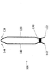
本発明の一態様によれば、膨張可能なクッション用のフィルムが提供される。フィルムは、第1長手端縁と第2長手端縁とを有する第1膜層、および第1長手端縁と第2長手端縁とを有する第2膜層を含む。第2膜層は、第1膜層と実質的に同一に広がるように並べられる。図1Aと1Bは、サイド膨張チャネルを画するように接合された第1および第2膜層を有するフィルムの見本となる態様の平面図および側面図である。図1Aと1Bに示すように、見本となるフィルム100は、第1および第2長手端縁122と124を備える第1膜層120と、第1および第2長手端縁142と144を備える第2膜層140を含む。第1および第2膜層120と140は実質的に同一に広がるように配置され、すなわち、少なくともそれぞれの第1端縁122と142は互いに揃えられ、および/またそれぞれの第2端縁124と144は互いに揃えられている。
According to one aspect of the present invention, an inflatable cushion film is provided. The film includes a first membrane layer having a first longitudinal edge and a second longitudinal edge, and a second membrane layer having a first longitudinal edge and a second longitudinal edge. The second film layer is arranged so as to spread substantially the same as the first film layer. 1A and 1B are plan and side views of a sample embodiment of a film having first and second membrane layers joined to define a side expansion channel. As shown in FIGS. 1A and 1B, a
図1Bに示されるように、見本となるフィルム100において揃えられた第1端縁122と142は互いに接合されておらず、一方、第2端縁124と144は互いに接合されている。このような構造は、膜材料(web material)の単一のシート、スリットが開けられた1つの端縁を有する膜材料を平らにしたチューブ、または2枚の膜材料から形成できる。例えば、第1および第2膜層120と140は、接合された第2端縁124と144をなすように折られた(例えば「c字状に折られたフィルム」)膜材料でできた一枚のシートを含みうる。あるいは、例えば、第1および第2膜層120と140は、揃えられた第1端縁122と142に沿って裂かれた膜材料のチューブ(例えば平たくされたチューブ)を含んでよい。さらに例えば、第1および第2膜層120と140は、揃えられた第2端縁124と144に沿って互いに接合、シール、またはその他の方法でくっつけられた2枚の互いに独立した膜材料を含んでもよい。
As shown in FIG. 1B, the
見本となるフィルム100は、当業者に知られた様々な膜材料のどれからも形成されうる。そのような膜材料は、限定はされないが、エチレン酢酸ビニル(EVA)、メタロセン、(低密度ポリエチレン(LDPE)、直鎖状低密度ポリエチレン(LLDPE)および高密度ポリエチレン(HDPE)のような)ポリエチレン樹脂、またはそれらの混合物を含む。開示されるフィルムは、中空チューブやソリッドコアに巻きつけられ、または扇形に折られた矩形体に、もしくは保管および出荷用の他の好ましい態様に折られてよい。
A
本発明の別の態様では、第1膜層と第2膜層を互いに接合する長手方向シールが設けられる。特に、ここでの態様としては、長手方向シールは、第1膜層の第1端縁および第2膜層の第1端縁の少なくとも1つ沿って連続的に延び、かつ、そこから横断方向に距離をあけて配置される。このようにして、長手方向シールと少なくとも1つの第1端縁との間にスカートが形成される。例えば、図1Aおよび1Bに描かれているここでの態様としては、見本のフィルム100は、第1および第2膜層120と140を接合し、揃えられた第1端縁122と142に沿って連続的に延びそこから距離をあけて配置された長手方向シール150を含む。長手方向シールは、揃えられた第1端縁122と142から距離Dで横断方向にずらして配置され、揃えられた第1端縁122と142と長手方向シール150との間に延び横断方向の幅Dを有するスカート160を形成する。所望により、第1端縁122と142は揃えなくてもよい。例えば、第2膜層140の第1端縁142は長手方向シール150に沿って配置され、スカート160は第1膜層120のみによって画される。ここでさらに述べられるように、スカート160は、ユーザが膨張したクッション190をつかむこと、また、ある態様では隣接する膨張したクッション190を分離することを容易にする。
In another aspect of the invention, a longitudinal seal is provided that joins the first and second membrane layers together. In particular, in this embodiment, the longitudinal seal extends continuously along at least one of the first edge of the first membrane layer and the first edge of the second membrane layer and transversely therefrom. Placed at a distance. In this way, a skirt is formed between the longitudinal seal and the at least one first edge. For example, in the embodiment illustrated herein in FIGS. 1A and 1B, the
長手方向シール150は、必須ではないが好ましくは実質的にまっすぐで、揃えられた第1および第2端縁122と142に実質的に平行であることが好ましい。長手方向シール150の他の変形もまた可能である。例えば、ある態様では、長手方向シール150は、第1および第2端縁122と142に沿って連続的に延びる波状のパターンあるいはジグザグ・パターン(当業者に理解されるものとしての波状およびジグザグとして)を含み、フィルム100の長手方向の広がりに沿って異なる横断方向の幅Dを備えるスカート160を形成する。さらに例えば、ある態様では、長手方向シール150は揃えられた第1端縁122と142に対して鋭角をなすよう傾斜される。
本発明の別の態様では、長手方向シールから第1膜層の第2端縁および第2膜層の第2端縁に向かって延びる一連の横断シールが設けられる。長手方向シールと隣接する一対の横断シールとにより形成される境界内にチャンバが画される。例えば、ここで図1Aに描かれる態様のように、見本のフィルム100は、フィルム100の長手方向への広がり沿って配置された一連の横断シール170を含む。各横断シール170は長手方向シール150の少なくとも近傍から接合された第2端縁124と144に向かって延びる。好ましくは、横断シール170は長手方向シール150を出発点として、接合された第2端縁124と144の方へ延びる。各横断シール170は、長手方向シール150近傍の第1端172と、フィルム100の接合された第2端縁124と144の近傍ではあるが好ましくは少し離れた位置にある第2端174とを有する。
In another aspect of the invention, a series of transverse seals are provided that extend from the longitudinal seal toward the second edge of the first membrane layer and the second edge of the second membrane layer. A chamber is defined within the boundary formed by the longitudinal seal and a pair of adjacent transverse seals. For example, as in the embodiment depicted herein in FIG. 1A, the
図1Aに具体的に示された各横断シール170は、実質的にまっすぐで、長手方向シール150に対して実質的に垂直に延びる。横断シール170の別のアレンジも可能である。例えば、ある態様では、横断シール170はここでさらに述べるように、波状のパターンかジグザグ・パターンを有する。
Each
図1Aに示すように、横断シール170は、長手方向シール150と実質的に直角に交差し、「T」字形をなす。あるいは、1以上の横断シール170の各々の一部が長手方向シール150の下まで延び、概ね「t」字形を持つ頂点をなすように、1以上の横断シール170が長手方向シール150を超えて延びて交差してもよい。
As shown in FIG. 1A, the
本発明の別の態様によれば、横断シールはそれぞれ、長手方向シール近傍の第1端と、第1膜層の第2端縁および第2膜層の第2端縁から横断方向に距離をあけて配置された第2端と、を有する。フィルムには、横断シールの第2端と第1および第2膜層の第2端縁との間に、長手方向チャネルが画される。長手方向チャネルは、フィルム中に画されたチャンバと流体連通する。例えば、ここで図1Aに描かれる態様のように、横断シール170の第2端174は、揃えられた第2端縁124と144から横断方向の寸法dで離れて配置され、揃えられた第2端縁124と144および第2端174の間に延びて横断方向の幅dを有する長手方向チャネル180を形成する。ここでさらに述べるように、長手方向チャネル180は、膨張可能なチャンバ190のためのサイド膨張チャネルとして機能する。
According to another aspect of the invention, the transverse seals are each transversely spaced from the first end near the longitudinal seal, the second edge of the first membrane layer and the second edge of the second membrane layer. And a second end disposed open. The film has a longitudinal channel defined between the second end of the transverse seal and the second edge of the first and second membrane layers. The longitudinal channel is in fluid communication with a chamber defined in the film. For example, as in the embodiment depicted herein in FIG. 1A, the
所望により、横断方向の距離Dと横断方向の寸法dは同程度の大きさで、その結果、スカート160と長手方向チャネル180とは同じ大きさとなる。ある態様では、横断方向の距離Dと横断方向の寸法dとは、対称となるよう実質的に等しい。別の方法として、他の態様では、横断方向の距離Dは横断方向の寸法dより実質的に小さい。しかしながらこのような態様でも横断方向の距離Dは、隣接する膨張チャンバ190をつかみ、分離することをスカート160が容易にするよう、十分な距離をとっていることが好ましい。
If desired, the transverse distance D and the transverse dimension d are of similar magnitude, so that the
長手方向シール150および横断シール170は(ここでさらに述べられる長手方向シール片と同様に)、当業者に知られた様々な技術のどれからでも形成可能である。そのような技術には、限定はされないが接着、摩擦溶接、溶融、ヒートシール、レーザーシール、また超音波溶接が含まれる。
1つの好ましい態様では、横断シール170の第2端174は、揃えられた第2端縁124と144から横断方向の寸法dで実質的に均一の距離で配置される。第2端174の他のアレンジも可能である。例えば、ある態様では、第2端174は、横断方向の異なる寸法dで、揃えられた第2端縁124と144から離れて配置され、フィルム100の長手方向の広がりに沿って異なる横断方向の幅dを持つ長手方向チャネルを形成する。このような態様の1つでは、隣接する一対の横断シール170の第2端の174の1つは、もう一方の第2端174に比べて揃えられた第2端縁124と144により近い距離にある。当業者には理解されようが、このようなアレンジは、膨張チャネル180からチャンバ190へのガスの流れを促進しうる。
In one preferred embodiment, the
長手方向シール150および隣接する一対の横断シール170は、共同して膨張可能なチャンバ190の境界を画する。図1Aに示すように、膨張可能なチャンバ190はそれぞれ、長手方向チャネル180に向かって開く開口198を介して長手方向チャネル180と流体連通し、ここでさらに述べられる膨張可能なチャンバ190の膨張を可能にする。
A
本発明の別の態様によれば、フィルムの第1膜層および第2膜層を横切って横断方向に延びる一連の脆弱なラインが提供される。横断方向の脆弱なラインはそれぞれ、第1および第2膜層の第1端縁と第1および第2膜層の第2端縁との間を延びる。例えば、ここで図1Aに描かれる態様のように見本のフィルム100は、フィルム100の長手方向の広がりに沿って配置され、第1および第2膜層120と140を横断方向に横切って延びる一連の脆弱なライン195を含む。横断方向の脆弱なライン195はそれぞれ、揃えられた第1端縁122と142の少なくとも近傍から、接合された第2端縁124と144に向かって延びる。好ましくは、横断方向の脆弱なライン195はそれぞれ、揃えられた第1端縁122と142から出発して長手方向シール150を横切り接合された第2端縁124と144まで延びて、隣接する膨張可能なクッションの分離を容易にする。
In accordance with another aspect of the present invention, a series of fragile lines are provided that extend transversely across the first and second membrane layers of the film. Each transverse line of weakness extends between the first edge of the first and second membrane layers and the second edge of the first and second membrane layers. For example, as in the embodiment depicted herein in FIG. 1A, a
横断方向の脆弱なライン195は、当業者に知られた種々の脆弱なラインのいずれを含んでもよい。例えば、ある態様では、横断方向の脆弱なライン195は、ミシン目の列を含み、一列のミシン目は列の横断方向への広がりに沿って間隔をあけて交互に配置されたランドとスリットを含む。ランドとスリットとは、列の横断方向の広がりに沿って規則正しく、または不規則に出現してよい。別の方法では、例えば、ある態様では横断方向の脆弱なラインは膜材料に形成された分割ラインまたはその同種のものを含む。
The transverse
横断方向の脆弱なライン195は、当業者に知られた様々な技術のどれからも形成しうる。限定はされないが、そのような技術には、カッティング(例えば棒、ブレード、ブロック、ローラおよびホイールのようなカッティング用の、またはギザギザの部材を用いる技術)および/または切り目つけ(スコアリング:例えば電磁気の(例えばレーザ)スコアリングおよび機械的なスコアリングのような、第1および第2膜層120と140の材料の強度や厚さを少なくする技術)を含む。
The transverse
見本のフィルム100の横断方向の脆弱なライン195はそれぞれ、隣接する一対のチャンバ190の間に配置される。より具体的には、横断方向の脆弱なライン195はそれぞれ、長手方向シール150と共同して隣接する膨張可能なチャンバ190の境界をなす、隣接する横断シール170の隣り合う2ペア177と179の間に配置される。
Each transverse
図1Aに示されるように、横断方向の脆弱なライン195それぞれと隣接し、それぞれを間にして配置される横断シール170(このような横断シールの組は図1Aでは176とラベルされている)は、幅wで分離されている。ある態様では、横断シール170のペア176はそれぞれ、やや幅狭の別の横断シール170のペアよりむしろ、幅Wのやや幅広の1つの横断シールを含む。このような態様の幾つかでは、横断方向の脆弱なライン195は、やや幅広のシールの幅wと揃えられその幅まで広がる。
As shown in FIG. 1A,
見本のフィルム100は、当業者に知られている様々な膨張およびシーリング技術のどれでもを使用して膨張され、シールされうる。このような技術は、フィルム構造体がサイド膨張チャネルに沿って膨張し、サイド膨張チャネルに隣接し結果的に膨らまされたチャンバをシールすることを可能とする膨張およびシーリング技術を含み、限定はされないが、米国特許第6,789,376号、米国特許出願第2004/0154728号、および英国特許出願公開第2,384,459Aの1以上に開示されているような技術を含む。好ましいシーリング技術では、結果として脹らまされたクッションはサイド膨張チャネルの近くでシールされ、揃えられた第1および第2膜層の第2端縁から分離される。例えば、このようなシーリング技術の1つでは、チャンバ190を膨張させた後、第1および第2膜層120と140は、接合された第2端縁124と144に連続的に沿って延び好ましくはそこから離れている長手方向シール領域Sで互いにシールされる。その後、フィルム100は、接合された第2端縁124と144に沿ってカットされ、スリットを入れられ、またはその他の方法で分離される。好ましい態様では、膨張チャネル180は、第1スカート160の反対側に第2スカート180をなすように第2端縁124と144に沿って裂かれる。別の方法では、第2端縁124と144の間の接合には、ミシン目が打たれ、あるいは他の方法で脆弱なラインが設けられてよく、チャンバを膨張およびシールした後に分離される。シーリングとカッティング操作は、同時に、または連続的に行なうことができる。図1Aにおいて、長手方向シール領域はSとラベルされたラインで概略、示されている。図1Aで示唆されるように、長手方向シール領域Sは、横断シール170の第2端174およびチャンバ190の開口198に沿って第1および第2膜層120と140を互いに接合する。膨張およびシール後、フィルム100は膨張したクッション199を形成し、そこではこのような膨張したクッション199はそれぞれ1つの膨張したチャンバ190を含む。フィルム100中の隣接する1以上の膨張したクッション199の房は、スカート160および/またはスカート180(つまり、長手方向シール領域Sと裂かれた第2端縁124と144との間に形成されたスカート)に沿ってつかまれ、横断方向の脆弱なライン195に沿って互いに分離されうる。
The
図2Aおよび2Bは、内側膨張チャネルを持つフィルムの見本となる態様の平面面および側面図である。図2Aおよび2Bに示されるように、見本のフィルム200は、図1Aおよび1Bに示された見本のフィルム100と多くの点で類似する。例えばフィルム200は、第1および第2長手端縁222と224を備える第1膜層220と、第1および第2長手端縁242と244を備える第2膜層240を含み、そこでは第1および第2膜層220と240は、互いに対して実質的に同一に広がるように配置されている。さらにここでさらに述べられるように、見本のフィルム200は、長手方向シール250a、250b、スカート260a、260b、横断シール270a、270b、開口298a、298を有する膨張可能なチャンバ290a、290b、および横断方向の脆弱なライン295を含む。図2Aに示されるように、フィルム200は、フィルム100のようなサイドチャネル180ではなく、チャンバ290を膨張させる内側(例えば、中央)長手方向チャンネル280を含む。
2A and 2B are plan and side views of a sample embodiment of a film having an inner inflation channel. As shown in FIGS. 2A and 2B, the
本発明の別の態様では、第1膜層および第2膜層を接合する第2長手方向シールが設けられる。第2長手方向シールは、第1膜層の第2端縁および第2膜層の第2端縁の少なくとも1つに沿って連続的に延び、それから横断方向に離れて配置される。第2長手方向シールと、少なくとも1つの第2端縁との間に第2スカートが形成される。例えば、また、ここで図2Aの中で描かれる態様ように、見本のフィルム200は、第1端縁222と242に沿って連続的に延びる第1長手方向シール250a、および第2端縁224と244に沿って連続的に延びる第2長手方向シール250bを含み、各々のシール250aと250bは、第1膜層220を第2膜層240に接合する。第1長手方向シール250aは、揃えられた第1端縁222と242から距離Daで横断方向にずれた位置に配置されて第1スカート260aを形成し、第2長手方向シール250bは、揃えられた第2端縁224と244から距離Dbで横断方向にずれた位置に配置されて第2スカート260bを形成する。横断方向の距離DaとDbは、膨張可能なチャンバ290a、290bの所望の相対的なサイズを基礎に選択しうる。対応する第1端縁122と142、対応する第2端縁124と144は、所望によって互いに接合してよく、または、接合しなくてもよい。
In another aspect of the invention, a second longitudinal seal is provided that joins the first membrane layer and the second membrane layer. The second longitudinal seal extends continuously along at least one of the second edge of the first membrane layer and the second edge of the second membrane layer, and is spaced transversely therefrom. A second skirt is formed between the second longitudinal seal and at least one second edge. For example, and as depicted herein in FIG. 2A, a
さらに、本発明では、第2長手方向シールから第1端縁へ延びる一連の第2横断シールが提供される。第2長手方向シールと隣接する一対の第2横断シールによって形成される境界の範囲に第2チャンバが画される。例えば、ここで図2Aの中で描かれる態様のように、見本のフィルム200はさらに、第1および第2膜層220と240を互いに接合する第1および第2の一連の横断シール270aと270bを含む。第1横断シール270aはそれぞれ、第1長手方向シール250aから第2端縁224と244へ延び、第2横断シール270bはそれぞれ、第2長手方向シール250bから第1端縁22と242へ延びる。第1横断シール270aはそれぞれ、第1長手方向シール250aの近傍の第1端272aと、第1長手方向シール250aから横断方向に離れた(つまり、第2端縁224と244の方向に離れた)第2端274aを有し、第2横断シール270bもまたそれぞれ、第2長手方向シール250bの近傍の第1端272bと、第2長手方向シール250bから横断方向に離れた(つまり、第1端縁222と242の方向に離れた)第2端274bを有する。図2Aの中で描かれるように、第1および第2横断シール270aと270bは互いに揃えてよく、所望によっては互いにずれていてもよい。
Furthermore, the present invention provides a series of second transverse seals extending from the second longitudinal seal to the first edge. A second chamber is defined in the region of the boundary formed by the pair of second transverse seals adjacent to the second longitudinal seal. For example, as in the embodiment depicted herein in FIG. 2A, the
本発明の別の態様によれば、第1チャンバおよび第2チャンバの間に配置される長手チャネルが設けられる。特に、第1横断シールの第2端と第2横断シールの第2端との間に長手方向チャンネルが画される。長方向チャネルは、第1チャンバおよび第2チャンバと流体連通する。例えば、ここで図2Aの中で描かれる態様のように、長手方向チャンネル280は、第1および第2横断シール270aと270bの第2端274aと274bとの間に画される。
According to another aspect of the invention, a longitudinal channel is provided that is disposed between the first chamber and the second chamber. In particular, a longitudinal channel is defined between the second end of the first transverse seal and the second end of the second transverse seal. The longitudinal channel is in fluid communication with the first chamber and the second chamber. For example, as in the embodiment depicted herein in FIG. 2A, the
第1長手方向シール250aと隣接する一対の第1横断シール270aは共同で、第1の膨張可能なチャンバ290aの境界を画し、第2長手方向シール250bと隣接する一対の第2横断シール270は共同で第2の膨張可能なチャンバ290bの境界を画する。第1および第2の膨張可能なチャンバ290aと290bは、長手方向チャネル280に向かって開いた開口298aと298bを介して長手方向チャネル280と流体連通し、長手方向チャネル280は第1および第2の膨張可能なチャンバ290aと290bの間に配置される。
A pair of first
見本のフィルム200は、当業者に知られた様々な膨張およびシーリング技術のどれでもを使用して、膨張およびシールされうる。このような技術は、フィルム構造体が内側(例えば中央の)膨張チャネルに沿って膨張し、内側チャネルに隣接しその結果膨らまされたチャンバをシールすることを可能とする膨張およびシーリング技術を含み、限定はされないが、ここで先に言及された特許または特許出願の1以上に開示された技術を含む。ここで、「内側膨張チャネル」という語は、膨張可能なチャンバの2つの隣接する房を分離する膨張チャネルを含むと理解されてよい。好ましいシーリング技術では、結果として脹らまされたクッションは内側膨張チャネルの近くでシールされ、揃えられた第1および第2の膜層の第2端縁から分離される。例えば、このようなシーリング技術の1つでは、チャンバ290aと290bを膨張させた後、フィルム200の長手方向の広がりに沿って連続的に延びる長手方向シール領域SaとSbに沿って第1および第2膜層220と240は互いにシールされ、フィルム200は、長手方向シール領域SaとSbの間に配置された分離領域Cに沿ってカットされ、スリットを入れられ、またはその他の方法で分離される。好ましい態様では、膨張チャネル280は、第1スカート260a、bの反対側に第2スカート260c、dをなすように分離領域Cに沿って裂かれる。別の方法では、分離領域Cには、ミシン目が打たれ、あるいは他の方法で脆弱なラインが設けられてよく、チャンバ290を膨張およびシールした後に分離される。図2Aで示唆されるように、長手方向シール領域Saは、横断シール270aの第2端274aおよび開口298aに沿って第1および第2膜層220と240を互いに接合し、長手方向シール領域Sbは、横断シール270bの第2端274bおよび開口298bに沿って第1および第2膜層220と240を互いに接合する。膨張およびシール後、フィルム200は膨張したクッション299aと299bを形成し、そこではこのような膨張したクッション299a、299bはそれぞれ単一の膨張したチャンバ290aと290bを含む。隣接する膨張したクッション299aと299bの房は、それぞれ、スカート260aおよび/またはスカート260c(つまり、長手方向シール領域Saと、分離領域Cとの間に形成されたスカート)およびスカート260bおよび/またはスカート260d(つまり、長手方向シール領域Sbと、分離領域Cとの間に形成されたスカート)に沿ってつかまれ、横断方向の脆弱なライン295に沿って互いに分離されうる。
The
図3A〜3Eは、本発明の別の態様であって、横断シールの間に配置された長手方向シール片を有するフィルム構造体の平面図である。図1Aおよび1Bの見本のフィルムについての別の態様が示されるが、当業者はこの別の態様の1以上の特徴は図2Aおよび2Bに示した見本のフィルムと組み合わせてもよいことを理解するだろう。さらに、図3A〜3Eのシールのアレンジは、所望により、従来のc字状の折り目や平たくされたチューブ状のフィルム構造体で用いることができる。 3A-3E are plan views of another embodiment of the present invention, a film structure having longitudinal seal pieces disposed between transverse seals. Although another embodiment for the sample film of FIGS. 1A and 1B is shown, those skilled in the art will appreciate that one or more features of this alternative embodiment may be combined with the sample film shown in FIGS. 2A and 2B. right. In addition, the seal arrangements of FIGS. 3A-3E can be used with conventional c-shaped folds or flattened tubular film structures as desired.
図3A〜3Eに示されるように、見本のフィルム300は、図1Aおよび1Bに示された見本のフィルム100と多くの点で類似する。例えば、フィルム300は、第1および第2長手端縁322と324を備える第1膜層320と、第1および第2長手端縁342と344を備える第2膜層340を含み、そこでは第1および第2膜層320と340は、互いに対して実質的に同一に広がるように配置されている。また例えば、見本のフィルム300は、長手方向シール350、横断シール370、サイド膨張チャネル380、サイド膨張チャネル380に向かって開く開口398を有する膨張可能なチャンバ390、および所望により、スカート360と同様、横断方向の脆弱なライン395を含む。横断シール370は、フィルム300の長手方向の広がりに沿って等間隔、一定していない、またはランダムな間隔で配置され得る。
As shown in FIGS. 3A-3E, the
本発明の別の態様では、チャンバの隣接する一対の横断シールの間に配置された少なくとも1つの長手方向シール片が設けられる。少なくとも1つの長手方向シール片は、隣接するチャンバ部分の間に流体通路を備えるチャンバの範囲にチャンバ部分を画する。例えば、ここで図3A〜3Eに描かれる態様のように、フィルム300はまた、第1および第2膜320と340を互いに接合する長手方向シール片352を含む。長手方向シール片352は、チャンバ390の横断シール370の間に配置され、チャンバ部分392と流体連絡路394を画する。図3A〜3Eに示されるチャンバ部分392は、図4、5、6Aおよび6Bに示されるチャンバ部分と同様に、多角形状である。
In another aspect of the invention, at least one longitudinal seal piece is provided disposed between a pair of adjacent transverse seals in the chamber. At least one longitudinal seal piece defines a chamber portion in the region of the chamber comprising a fluid passage between adjacent chamber portions. For example, as in the embodiment depicted herein in FIGS. 3A-3E, the
図3A〜3Eに示されるように、フィルム300中のチャンバ390はそれぞれ、チャンバ390の横断方向への広がりに沿って配置された長手方向シール片352を含む。一般に、長手方向シール片352によって画されたチャンバ部分392および流体通路394は、膨張チャンバ390にかかる衝撃負荷の分散を促進でき、それによって、膨張チャンバ390の空間充填および性能特性を高める。当業者に理解され、また、図3Aに示唆されるように、相互接続されたチャンバ部分396に沿って第1チャンバ391にまたはその近くにかかる衝撃負荷を分散させるため、流体通路394は、第1チャンバ部分、例えばチャンバ部分391の気体(またはガス)の体積および圧力が、流体通路394を介して接続されたチャンバ部分に送られることを可能とする。流体通路394はまた、膨張したフィルム300が包装される物体の形に合わせられるよう、流体通路394を通るラインに沿って膨張チャンバ390を曲げ、折り目をつけ、折り畳むことを容易にする。
As shown in FIGS. 3A-3E, each
図3A〜3Eに示されるように、長手方向シール片352はそれぞれ、長手方向シール350と共同で膨張可能なチャンバ390の境界を画する一対の横断シール370の間に配置される。長手方向シール片352はそれぞれ、横断方向の幅を有し、長手方向の寸法で互いに隔てられた一対の向かい合う端354と356を含む。図3A〜3Eに描くように、端354と356は、隣接する横断シール370からずらされている場合、コーナーの領域で空気(またはガス)の体積または圧力が集積するのを妨げ、または防ぐために丸く、あるいは他の方法でなだらかにされたコーナー(つまり、終端部分)を好ましくは含み、それによりチャンバ部分392の間で衝撃負荷が分散されることを容易にする。流体通路394はそれぞれ、長手方向シール片352の長手方向の寸法より短いが、チャンバ部分392の間での衝撃負荷の分散(例えば通気)を許容するに十分なだけの長手方向の寸法を有する。好ましい態様の長手方向シール片352は実質的にまっすぐで、長手方向シール350に対して実質的に平行に延びる。
As shown in FIGS. 3A-3E, each
図3Aに示されるように、各チャンバ390長手方向シール片352は、チャンバ390の各横断シールの間に、長手方向の距離xで等間隔に距離をあけて中心に配置される。チャンバ390の長手方向シール片352の別のアレンジも可能である。例えば、図3Bに示されるように、長手方向シール片352はチャンバ390内に交互に、あるいはずらして配置してもよく、横断シール370に対して長手方向シール片352の端354と356から、x≠yであるような、長手方向に異なる距離xとyで離れた位置に端354と356が配置されるようにしてもよい。また、例えば図3Cに示すように長手方向シール片352は、x>yとなるように、チャンバ390の横断シールの1つに近づいて配置されてもよい。
As shown in FIG. 3A, each
図3A〜3Cに示されるように、長手方向シール片352はチャンバ390内で横断方向に実質的に均一な間隔で配置され、その結果、チャンバ390の長手方向シール片352はそれぞれ、他のチャンバ390それぞれの長手方向シール片352と横断方向に揃えられている。図3Aに示される態様のようないくつかの態様では、長手方向シール片352は、チャンバ390の長手方向の寸法Wcと実質的に同一であるような横断方向の間隔Tで配され、実質的に矩形のチャンバ部分を形成する。チャンバ390の長手方向シール片352の他のアレンジも可能である。例えば図3Dに示されるように長手方向シール辺352は、チャンバ(例えばチャンバ395)の少なくとも1つの長手方向シール片(例えば片353)が隣接するチャンバ(例えばチャンバ397)の隣接する一対の長手方向シール片(例えば片355と357)の間において横断方向にずらされているように、チャンバ390に配置されてもよい
As shown in FIGS. 3A-3C, the
図3A〜3Eに示される見本となるフィルム300は、ここで先に述べられたような膨張およびシーリング技術を用いて膨張およびシールされ得る。例えば、図3Aで示唆されるように、第1および第2膜層320と340は、長手方向シール領域Sに沿ってシールされ、接合された第2端縁324と344に沿って裂かれ、カットされ、あるいはミシン目打ちやそれに類するような他の方法で分離される。膨張およびシーリングの後、フィルム300は膨張したクッション399を形成し、膨張したクッション399はそれぞれ少なくとも1つ、好ましくは1より多い独立の膨張したチャンバ390を含み、独立の膨張したチャンバ390はそれぞれチャンバ部分392と流体通路394を含む。隣接する膨張したクッション399は、備えられていればスカート360aおよび/または380(つまり、長手方向シール領域Sと裂かれた第2端縁324と344との間に形成されたスカート)に沿ってつかまれ、横断方向の脆弱なライン395に沿って互いに分離され得る。
The
図3A〜3Eに示すように、長手方向シール片352は膨張可能なチャンバ390の開口398を画し、開口398は膨張チャネル380と流体連通可能とする。他の態様では、長手方向シール片352は、開口398の近傍に配置された長手方向シール片を含む。
As shown in FIGS. 3A-3E, the
本発明の他の態様では、チャンバの開口近傍に配置された、少なくとも1つの長手方向シール片が設けられる。例えば、また、ここで図3Eに描かれる態様のように、長手方向シール片352は、チャンバ390の開口398近傍に配置され、横断シール370からずらされた(例えばそれらの間の中央に配置された)長手方向シール片362を含む。長手方向シール片362はそれぞれ、チャンバ390の一対の横断シール370の第2端374と横断方向に実質的に揃えられている。好ましくは、長手方向シール片362はそれぞれ、チャンバ390内に配置された長手方向シール片352の横断方向の幅より大きい横断方向の幅を有する。好ましくは、長手方向シール片は先に述べたように丸く、またはなだらかにされたコーナーを備える。長手方向シール片362の横断方向の幅が大きいほど、チャンバ390の膨張後、長手方向シール領域Sに沿ってチャンバ390の開口398を終局的にシールしやすくなる。
In another aspect of the invention, at least one longitudinal seal piece is provided that is disposed near the opening of the chamber. For example, also as in the embodiment depicted herein in FIG. 3E, the
一般的に、長手方向シール領域Sは長手方向シール片362を横切る。ある態様では、長手方向シール領域Sは長手方向シール片362の中央部分を横切る。例えば、図3Eに示すように好ましい態様では、長手方向シール領域Sは、長手方向シール片362を概ね二つに分けるが、長手方向シール領域Sおよび長手方向シール片362の他の横断配置もまた可能である。
In general, the longitudinal seal region S traverses the
図1Aおよび1Bの態様と同様、一連の脆弱なラインが設けられる。所望により、図1Aに示すように隣接する一対の横断シール370の間に脆弱なラインが配置されるように、一対の横断シール370が図3A〜3Eの態様に備えられてもよい。図3Eに示すように、脆弱なライン395はそれぞれ、特定のチャンバ390を横断してよく、これによりその特定のチャンバ390を膨張させられない状態とする。あるいは、また、先に述べたとおり、脆弱なライン395は選ばれた横断シール370と揃えられてもよい。所望により、図3A〜3Eに示すフィルムの横断シール370は、少なくとも幾つかの比較的幅狭のシールと少なくとも幾つかの比較的幅広のシール370を含んでもよい。このようにして脆弱なライン395はそれぞれ、比較的幅広のシール370に隣接するチャンバ390を横切ることなく比較的幅広の横断シール370と並べられてそれを通って延び、それにより隣接するチャンバ390が膨張される可能性を残す。横断シールおよび横断方向の脆弱なラインのこのようなアレンジは、ここで開示されるそれぞれのフィルムに適用されうる。
Similar to the embodiment of FIGS. 1A and 1B, a series of fragile lines are provided. If desired, a pair of
図3Eに示すように、チャンバ390の一対の横断シール370の第2端374と、チャンバ390の開口近傍に配置された長手方向シール片362とは、共同して膨張チャネル380からチャンバ390に向かう2つの独立した入口ポート398aと398bを画する。膨張可能なチャンバ390はそれぞれ、独立した2つの流体流路を介して膨張チャネル380と流体連通する。さらに、膨張可能なチャンバ390はそれぞれ、2つの独立した流体流路を介して他の膨張可能なチャンバ390と連通する。
As shown in FIG. 3E, the
膨張チャネルから膨張可能なチャンバに向かう、または隣接するチャンバ部分の間の入口ポートの他のアレンジも可能である。例えば、他の態様では、各チャンバはチャンバの開口近傍に配置された2またはそれ以上の長手方向シール片を含んでよく、そこでは、長手方向シール片と各チャンバの隣接する一対の横断シールの第2端は、3以上の入口ポートをチャンバの中に画する。 Other arrangements of the inlet port from the expansion channel to the inflatable chamber or between adjacent chamber portions are possible. For example, in another aspect, each chamber may include two or more longitudinal seal pieces disposed near the chamber opening, wherein the longitudinal seal pieces and a pair of adjacent transverse seals in each chamber are included. The second end defines three or more inlet ports into the chamber.
図3A〜3Eに示すように、フィルム300において横断方向の脆弱なライン395は横断シール370に対して長手方向にランダムな間隔で配置される。そのため、横断方向の脆弱なライン395はチャンバ390を通って(例えば、チャンバ390の長手方向シール片352と362を通って)延びてよい。あるいは、図1A、1B、2Aおよび2Bに関して示して述べたような間隔と同様、横断方向の脆弱なライン395は横断シール370に対してフィルム300で長手方向に規則正しい間隔で配置されてもよい。
As shown in FIGS. 3A-3E, transverse
図4は、本発明の他の態様に関し、横断シールから延びる長手方向シール片を有するフィルムの他の態様の平面図である。図1Aと1Bの見本のフィルムについて別の態様のフィルムが記載されるが、この別の態様の1以上の特徴は図2Aおよび2Bに示した見本のフィルムと組み合わせられてもよい。さらに、スカートが設けられないよう、従来のc字状の折り目や平たくされたチューブ構造体が用いられてもよい。 FIG. 4 is a plan view of another embodiment of a film having a longitudinal seal piece extending from a transverse seal in accordance with another embodiment of the present invention. Although another embodiment of the film is described for the sample film of FIGS. 1A and 1B, one or more features of this alternate embodiment may be combined with the sample film shown in FIGS. 2A and 2B. Further, a conventional c-shaped fold or flattened tube structure may be used so that no skirt is provided.
図4に示すように、見本のフィルム400は図1Aおよび1Bに示された見本のフィルム100および図3A〜3Eに示された見本のフィルム300と類似する。例えば、フィルム400は、第1および第2長手端縁422と424を備える第1膜層420と、第1および第2長手端縁424と444を備える第2膜層440を含み、そこでは第1および第2膜層420と440は、互いに対して実質的に同一に広がるように配置されている。また例えば、見本のフィルム400は、長手方向シール450、第1および第2端472と474を有する横断シール470、膨張チャネル480、サイド膨張チャネル480に向かって開いた膨張可能なチャンバ490、および所望により、スカート460と同様、横断方向の脆弱なライン495を含む。
As shown in FIG. 4, the
本発明の他の態様では、少なくとも1つの横断シールから延びる少なくとも1つの長手方向シール片が設けられる。例えばここで図4に描いた態様のように、見本のフィルム400はまた、チャンバ490の横断シール470から延び、チャンバ部分492と流体連絡路494を画する長手方向シール片433を含む。
In another aspect of the invention, at least one longitudinal seal piece extending from at least one transverse seal is provided. For example, as in the embodiment depicted herein in FIG. 4, the
長手方向シール433はそれぞれ、チャンバ490の横断シール470の1つから延びて横断シール470を向かい側にして配置されるコーナー(つまり終端部)439を含む。好ましくは、終端部439は、終端部439の領域で空気(またはガス)の体積または圧力が集積するのを妨げ、または防ぐために丸くされた、あるいは他の方法でなだらかにされている。図4に示すように、長手方向シール片433は好ましくは横断シールの第2端474の近傍に配置された長手方向シール片473を含む。長手方向シール473はそれぞれ、チャンバ490の横断シール470の1つの第2端474から延びて、第2端474を向かい側とするコーナー(つまり終端部)479を含む。チャンバ490の長手方向のシール片473の終端部479は、長手方向膨張チャネル480からチャンバ490に向かう入口ポート485を共同して画する。好ましくは、入口ポート485は、流体通路494の長手方向の寸法と実質的に等しいが長手方向シール片433と473の長手方向の寸法より短い長手方向の寸法を有する。長手方向シール片473は、チャンバ390を膨張させた後、長手方向シール領域Sに沿ってチャンバ490の入口ポート485を終局的にシールしやすくする。図3Eの長手方向シール片362のように、長手方向シール片473は、入口ポート485のシールをさらに容易にするために、広げられたあるいはより大きい横断方向の幅を有してもよい。
Each
図4に示すように、長手方向シール片433と473は実質的に同じ長手方向寸法を有し、フィルム400において実質的に均一な横断方向の間隔で配置されている。長手方向シール片433と473についての別の配置やサイズもまた可能である。例えば、ある態様では長手方向シール片433の長手方向の寸法は長手方向シール片473の長手方向幅と異なってもよい。また例えば、ある態様では長手方向シール片433および/または473は、図3Bおよび3Dのフィルム300の長手方向シール片352の交互配置と同様に、フィルム400中で交互にまたはずらして配置してもよい。
As shown in FIG. 4, the
図5は、図1Aおよび1Bに示したフィルムの別の態様であって、横断シールと、横断シールから延びる長手方向シール片との間に配置される長手方向シール片を備えるものの平面図である。図1Aおよび1Bの見本のフィルムについての別の態様が示されるが、この別の態様の1以上の特徴は図2Aおよび2Bに示される見本のフィルムと組み合わされてもよい。あるいは、スカートが設けられないように、従来のc字状の折り目や平たくされたチューブ状のフィルム構造体も使用されうる。 FIG. 5 is a plan view of another embodiment of the film shown in FIGS. 1A and 1B, comprising a longitudinal seal piece disposed between a transverse seal and a longitudinal seal piece extending from the transverse seal. . Although another embodiment for the sample film of FIGS. 1A and 1B is shown, one or more features of this alternative embodiment may be combined with the sample film shown in FIGS. 2A and 2B. Alternatively, a conventional c-shaped fold or flattened tube-like film structure may be used so that no skirt is provided.
図5に示すように、見本となるフィルム500は図1Aおよび1Bに示す見本となるフィルム100および図3A〜3Eに示す見本となるフィルム300と多くの点で類似する。例えば、フィルム500は、第1および第2長手端縁522と524を備える第1膜層520と、第1および第2長手端縁542と544を備える第2膜層540を含み、そこでは第1および第2膜層520と540は、互いに対して実質的に同一に広がるように配置されている。また例えば、見本のフィルム500は、長手方向シール550、第1および第2端572と574を有する横断シール570、膨張チャネル580、膨張チャネル580に向かって開く膨張可能なチャンバ590、および所望により、スカート560と同様、横断方向の脆弱なライン595を含む。さらに、見本となるフィルム500は、チャンバ590の横断シール570の間に配置され、チャンバ部分592と流体連絡路594とを画する長手方向シール片552を含む。図5に示すように、見本となるフィルム500はまた、横断シール570の第2端574から延びる長手方向シール片564を含む。
As shown in FIG. 5, the
長手方向シール片564はそれぞれ、チャンバ590の一対の横断シール570の1つの第2端574から延び、第2端574を向かい側として配置されるコーナー(つまり終端部)566を含む。好ましくは、終端部5669は、終端部566の領域で空気(またはガス)の体積または圧力が集積するのを妨げ、または防ぐために丸くされた、あるいは他の方法でなだらかにされている。チャンバ590の終端部566は、長手方向膨張チャネル580からチャンバ590に向かう入口ポート585を共同して画する。好ましくは、入口ポート585は、長手方向シール片552の長手方向の寸法より小さく流体通路594の長手方向の幅より大きい長手方向の寸法を有する。また好ましくは、長手方向シール片564はそれぞれ、長手方向シール片552の横断方向幅より大きい横断方向の幅を有する。当業者に理解される通り、長手方向シール片564の横断方向の幅を増やすと、膨張後、長手方向シール領域Sに沿ってチャンバ590の入口ポート585を終局的にシールしやすくなる。
Each
図6A〜6Dは、ジグザグ・パターンの横断シールを備える、図1Aと1Bに示したフィルムの別の態様の平面図である。図1Aおよび1Bの見本のフィルムについての別の態様が示されるが、この別の態様の1以上の特徴は図2Aおよび2Bに示される見本のフィルムと組み合わされてもよい。さらに、スカートを備えないように、従来のc字状の折り目や平たくされたチューブ状のフィルム構造体も使用されうる。 6A-6D are plan views of another embodiment of the film shown in FIGS. 1A and 1B with a zigzag pattern of transverse seals. Although another embodiment for the sample film of FIGS. 1A and 1B is shown, one or more features of this alternative embodiment may be combined with the sample film shown in FIGS. 2A and 2B. Further, a conventional c-shaped fold or flattened tube-like film structure may be used so as not to have a skirt.
図6A〜6Dに示すように、見本となるフィルム600は図1Aおよび1Bに示す見本となるフィルム100と多くの点で類似する。例えば、フィルム600は、第1および第2長手端縁622と624を備える第1膜層620と、第1および第2長手端縁642と644を備える第2膜層640を含み、そこでは第1および第2膜層620と640は、互いに対して実質的に同一に広がるように配置されている。また例えば、見本のフィルム600は、長手方向シール650、第1および第2端672と674を有する横断シール670、膨張チャネル680、膨張チャネル680に向かって開く膨張可能なチャンバ690、および所望により、スカート660と同様、横断方向の脆弱なライン695を含む。
As shown in FIGS. 6A-6D, the
図1Aおよび1Bに示すフィルム100について述べたとおり、スカート660は、膨張したチャンバ690をつかむこと、また、ある態様では隣接する膨張したチャンバ690を分離することを容易にする。一般的に、スカートがどの程度、膨張したチャンバのつかみと分離を容易にするかはチャンバが形成される横断方向の拡がりによる。スカートは、設けられていれば、比較的小さな横断方向の幅を有するフィルムで形成された膨張したチャンバに比べて、比較的大きな横断方向の幅(例えば36インチまたはそれ以上の幅)を有するフィルムで形成された膨張したチャンバの分離をより容易にする。
As described for the
本発明の別の態様によれば、複数の横断シールはそれぞれジグザグ・パターンを有する。例えば、ここで図6A〜6Dに描かれている態様のように、見本となるフィルム600の横断シール670はそれぞれ、ジグザグ・パターンを含む。ここでは「ジグザグ・パターン」という語は、急峻な(つまり、不連続な)カーブやコーナーを有するパターンを含む。
According to another aspect of the invention, each of the plurality of transverse seals has a zigzag pattern. For example, as in the embodiment depicted herein in FIGS. 6A-6D, each
ジグザグ・パターンを有する横断シール670はそれぞれ、長手方向シール650の少なくとも近傍から第1および第2膜層620と640の接合された第2端縁624と644に向かって延びる。チャンバ690は、長手方向シール650と隣接する一対の横断シール670とにより画される。図3A〜3E、4、および5のフィルム構造体と同様に、またさらに本発明の別の態様によれば、各チャンバ390はおおむね多角形の複数のチャンバ部分に分けられる。各チャンバの隣接するチャンバ部分は流体通路で相互接続され互いに流体連通する。
A
ある態様では、図6A、6Bおよび6Cに示すように、横断シール670はそれぞれ、比較的まっすぐな一群のシール片671を含み、隣接するシール片同士は急に曲がるコーナー673を形成する。あるいはある態様では図6Dに示す態様のように横断シール670はそれぞれ、クロスハッチの、あるいはベタの一群のシール片631を含み、隣接するクロスハッチ模様のシール片631は互いに向き合いコーナー673を形成する。
In one aspect, as shown in FIGS. 6A, 6B, and 6C, each
先に述べたように、横断シールの各ペアのジグザグ・パターンは、隣接するチャンバ部分の間に流体通路を形成した状態で、チャンバ内に実質的に多角形状の複数のチャンバ部分を画する。例えば、ここで図6A〜6Dに描かれる態様のように、チャンバ690の横断シール670のペアはそれぞれ、チャンバ内に多角形状のチャンバ部分692と、チャンバ部分694を接続する流体通路694を画する。多角形状のチャンバ部分は規則正しい多角形(つまり各辺が同じ長さで全ての辺が共通の中心の周囲に対照的に配置されているn面形状)または不規則な多角形状を有してよい。ここで、「多角形状のチャンバ部分」という語は、文脈からそうでないことが示唆されない限り、規則正しいおよび不規則な多角形状を有する多角形状部分を含む。
As previously mentioned, the zigzag pattern of each pair of transverse seals defines a plurality of substantially polygonal chamber portions within the chamber with fluid passages formed between adjacent chamber portions. For example, as in the embodiment depicted herein in FIGS. 6A-6D, each pair of
横断シール670は、図6Aおよび6Bに示される見本のフィルム600では概ね六角形のチャンバ部分を画し、図6Cおよび6Dに示される見本のフィルム600では概ね八角形のチャンバ部分を画する。チャンバ部分の他の形もまた、可能である。例えば、横断シール670は単独でまたは長手方向シール片とともに、先に述べたとおり4面のチャンバ部分(例えば長方形、ひし形、正方形、または台形のチャンバ部分)、5面の多角形チャンバ部分(例えば5角形のチャンバ部分)、および他のn面のチャンバ部分を画してよい。
The
好ましい態様では、また、図6A〜6Dに示すようにチャンバ690の横断シール670は、チャンバ690の横断方向の軸を通る鏡面の周囲で互いに実質的に鏡像となる(つまり、180度位相がずれている)。隣接する横断シール670の間のこのような関係は、第1チャンバ690において規則正しい多角形状のチャンバ部分692を形成し、隣接する第2チャンバ690において横断方向にずらされた多角形状のチャンバ部分692を形成する。例えば、図6Aに示すように、チャンバ(例えばチャンバ695)の少なくとも1つのチャンバ部分(例えば部分692a)は、隣接するチャンバ(例えばチャンバ697)における隣接する一対のチャンバ部分(例えば部分692bと692c)の間で横断方向にずらされている。このような関係はまた、隣接する第2チャンバ690のチャンバ部分692と横断方向で並べられた流体通路694を第1チャンバ690において形成する(例えば、隣接するチャンバ部分692の中心を通る長手方向軸にある流体通路694)。例えば、図6Aに示すように、第1チャンバ(例えばチャンバ697)の流体通路694は、隣接するチャンバのチャンバ部分(例えばチャンバ695の部分692a)と横断方向で揃えられる(つまりその中心を通る長手方向軸上にある)。
In a preferred embodiment, and as shown in FIGS. 6A-6D, the
図6A〜6Dに示すように、見本のフィルム600は好ましくは横断シール670の第2端に配置されたシールアーム643を含む。各シールアーム643は、横断シール670の第2端674並びに第1および第2膜層620と640の第2端縁624と644の間に配置される。隣接するシールアーム643の各ペアはチャンバ690に対して入口ポート685を画する。好ましくは、チャンバ690の隣接するシールアーム643は、チャンバ690の横断方向の軸の周囲で互いに実質的に鏡像となっている。シールアーム643は膨張後、長手方向シール領域Sに沿ってチャンバ690の入口ポート685の終局的にシールすることを容易にする。
As shown in FIGS. 6A-6D, the
図6A〜6Dに示すように、そしてここでの好ましい態様として、少なくとも幾つかの横断方向の脆弱なライン695が横断シール670およびこれに接続されたシールアーム643と揃えられ、これを通って延びる。ここで先に述べたアレンジのように、横断方向の脆弱なライン695の他のアレンジもまた可能である。
As shown in FIGS. 6A-6D, and as a preferred embodiment herein, at least some transverse
ある態様では、見本のフィルム600は長手方向シール片を含む。例えば、図6Bおよび6Dに示すように、見本のフィルム600は、各チャンバ690の横断シール670から延びる長手方向シール片633を含む。チャンバ690の長手方向シール片633は、チャンバ690内で多角形状のチャンバ部692と流体通路694とを画する。長手方向シール片673aは、膨張したチャンバ690を曲げ、折り目を付け、折り畳み、および/またはその他の方法で変形することを容易にし、フィルム600で包装される物体の形に合うようにする。好ましくは、チャンバ690の長手方向シール片633は、チャンバ690の図6Bに描かれるように、横断シール670に画される隣接したコーナー673から延びる。このような配置はチャンバ部分692の体積を大きくする傾向がある。図6Bおよび6Dに示すように、チャンバ690の長手方向シール片633は互いに横断方向に揃えられ、一方、隣接するチャンバ690の長手方向シール片633は互いに対して横断方向にずらされている。図6B〜6Dに示すように、長手方向シール片633は比較的幅狭の長手方向シール片(つまり、図6Bおよび6Dの長手シール片633のように、長手方向シール片が延びる起点となっている横断シール670の長手方向寸法と概ね同じか短い横断方向の幅を持つ長手方向シール片)、または比較的幅広の長手方向シール片(つまり、図6Cの長手シール片633のように、長手方向シール片が延びる起点となっている横断シール670の長手方向寸法より大きい横断方向の幅を持つ長手方向シール片)を含んでよい。ここで先に述べたアレンジのように、長手方向シール片633の他のアレンジも可能である。
In one embodiment, the
ここで具体的に示され、図6Aおよび6Bに描かれるように、見本となるフィルム600では隣接するチャンバ690の間にデッドスペース(つまり、フィルム600の膨張させられない部分)はなく、あるいは小さなものでしかない。隣接するチャンバ690の間のこのような近接した間隔は、第1および第2膜層の材料の無駄を低減する傾向がある。
As specifically shown here and depicted in FIGS. 6A and 6B, the
図示された態様を参照して、開示に係るフィルムが示され、説明されてきたが、本開示および添付の請求項の範囲内で変形が可能である。 While the disclosed film has been shown and described with reference to the illustrated embodiments, variations are possible within the scope of this disclosure and the appended claims.
例えば、見本となるフィルムはそれぞれ、互いに実質的に同一の広がりを持つように揃えられた第1および第2膜層を含む。ここで開示されるフィルムは、所望により、互いに実質的に同一ではなく広がる第1および第2膜層を含んでよい。 For example, each sample film includes first and second film layers that are aligned to be substantially coextensive with one another. The films disclosed herein may optionally include first and second membrane layers that are not substantially identical to each other and that extend.
また例えば、見本のフィルムはそれぞれ、接合されていない第1端縁と接合された第2端縁を有する第1および第2膜層を含んでもよい。ここで開示されるフィルムは第1および第2端縁の両方に沿って、または第1および第2端縁のどちらにも沿わずに接合された第1および第2膜層を含んでもよい。例えば、第1および第2膜層は、接合された第2端縁の周囲で折り曲げられ第1端縁に沿って互いにシールされた膜材料でできた単一のシート、第1端縁および第2端縁に沿って接合された膜材料でできたチューブ、または第1端縁および第2端縁に沿って互いに接合され、シールされ、あるいは他の方法でくっつけられた膜材料でできた2枚の独立したシートを含んでもよい。 Also, for example, each sample film may include first and second membrane layers having a first edge that is not joined and a second edge that is joined. The films disclosed herein may include first and second membrane layers joined along both the first and second edges, or along neither the first or second edges. For example, the first and second membrane layers may be a single sheet of membrane material that is folded around the joined second edges and sealed together along the first edges, the first edges and the first edges. A tube made of membrane material joined along two edges, or made of membrane material joined together, sealed, or otherwise attached together along the first and second edges It may include one independent sheet.
また例えば、見本となるフィルムのそれぞれは、第1および第2膜層を互いに接合する長手方向シールに対して実質的に垂直な向きの横断シールを含んでもよい。ここで開示されるフィルムは、また代わりに、長手方向シールに対してある角度の向きの横断シールを含んでもよい。 Also, for example, each of the sample films may include a transverse seal oriented substantially perpendicular to the longitudinal seal joining the first and second membrane layers together. The films disclosed herein may also alternatively include a transverse seal oriented at an angle with respect to the longitudinal seal.
また例えば、見本となるフィルムのそれぞれは、第1および第2膜層を互いに接合する長手方向シールを含む。所望により、ここで開示されるフィルムは、このような長手方向シールのない第1および第2膜層を含んでもよい。例えば、ここで開示されるフィルムは、それぞれの第1端縁およびそれぞれの第2端縁に沿って互いに接合され、シールされ、あるいはその他の方法でくっつけられた第1および第2膜層を含んでよく、そこでは横断シールが、接合された第1端縁の少なくとも近傍から接合された第2端縁に向かって延びる。 Also, for example, each of the sample films includes a longitudinal seal that joins the first and second membrane layers together. If desired, the films disclosed herein may include first and second membrane layers without such a longitudinal seal. For example, the films disclosed herein include first and second membrane layers that are bonded together, sealed, or otherwise attached together along respective first edges and respective second edges. Wherein the transverse seal extends from at least the vicinity of the joined first edge toward the joined second edge.
以上のように、ここで述べられたフィルムと方法はここで述べられた態様に限定されず、言及された以外の実践態様を含んでよく、流布している法律の下で許され得る限り広く解されるべきである。 As described above, the films and methods described herein are not limited to the embodiments described herein, but may include practical embodiments other than those mentioned, and are as broad as permitted under the spreading law. Should be understood.
断らない限り、「a」や「an」はここでは名詞を修飾するために用いられ、1またはそれ以上の修飾されたその名詞を含むと解され得る。 Unless stated otherwise, “a” and “an” are used herein to modify a noun and may be understood to include one or more modified nouns.
Claims (13)
第1膜層と、前記第1膜層と接合される第2膜層と、
前記第1膜層と前記第2膜層との間の空間に含まれる、流体、空気、又はガスのいずれかを受け入れる開口を有する長手方向の膨張チャネルと、前記第1膜層と前記第2膜層とを接合する複数の横断シールにより定義されて前記長手方向の膨張チャネルと流体連通される複数の横断方向のチャンバと、
前記複数の横断方向のチャンバの開口部にそれぞれ配置されて前記長手方向の膨張チャネルと前記複数の横断方向のチャンバとの間にそれぞれ前記長手方向の膨張チャネルと前記横断方向のチャンバとの間で流体連通させる複数のチャネルを定義する複数のシール片と、を備え、
前記複数のシール片は、前記長手方向に所定の長さで前記第1膜層と前記第2膜層とを接合して形成されることを特徴とするフィルム。An inflatable cushion film,
A first film layer; a second film layer joined to the first film layer;
A longitudinal expansion channel having an opening for receiving either fluid, air, or gas, contained in a space between the first membrane layer and the second membrane layer, the first membrane layer, and the second membrane layer; A plurality of transverse chambers defined by a plurality of transverse seals joining the membrane layer and in fluid communication with the longitudinal inflation channel;
Between each of the longitudinal inflation channel and the transverse direction of the chamber between the front Symbol plurality of respectively arranged in the opening of the transverse chamber said longitudinal inflation channel and the plurality of transverse chambers comprising a plurality of seal segments defining a plurality of channels providing fluid communication in a,
Wherein the plurality of sealing pieces, and the longitudinal direction is formed by bonding the second film layer and the first layer at a predetermined length, wherein Rukoto film.
前記複数の長手方向シール片は、前記複数の長手方向シール片の各々の端と隣接する前記複数の横断シールのいずれか一つとの間にそれぞれ複数の流体通路を定義するように配置されることを特徴とする請求項1に記載のフィルム。A plurality of longitudinal seals arranged to join the first membrane layer and the second membrane layer and to define a plurality of substantially square chamber portions, respectively, within the plurality of transverse chambers. Further including a piece,
The plurality of longitudinal seal pieces are arranged to define a plurality of fluid passages, respectively, between each end of the plurality of longitudinal seal pieces and any one of the adjacent transverse seals. The film according to claim 1.
前記複数の長手方向シール片は、前記フィルムを膨張させたときに前記複数の長手方向シール片の各々に沿って、前記フィルムを、前記横断方向とほぼ直角な方向である長手方向に折ることを容易にするように構成されることを特徴とする請求項2に記載のフィルム。The plurality of transverse seals are configured to facilitate the transverse folding of the film along each of the plurality of transverse seals when the film is expanded;
The plurality of longitudinal seal pieces fold the film in a longitudinal direction that is substantially perpendicular to the transverse direction along each of the plurality of longitudinal seal pieces when the film is expanded. The film of claim 2, wherein the film is configured to facilitate.
前記複数の多角形状チャンバ部分は、隣接する前記横断シールの前記直線状のシール片の間がもっとも狭くなる位置で、隣接するもの同士が互いに流体連通されることを特徴とする請求項11に記載のフィルム。The linear seal piece is arranged to divide the transverse chamber into a plurality of polygonal chamber portions;
12. The plurality of polygonal chamber portions are adjacent to each other in fluid communication with each other at a position where the space between the linear seal pieces of the adjacent transverse seals is the narrowest. Film.
Applications Claiming Priority (3)
| Application Number | Priority Date | Filing Date | Title |
|---|---|---|---|
| US11/123,090 US7862870B2 (en) | 2005-05-06 | 2005-05-06 | Films for inflatable cushions |
| US11/123,090 | 2005-05-06 | ||
| PCT/US2006/016971 WO2006121725A2 (en) | 2005-05-06 | 2006-05-03 | Films for inflatable cushions |
Related Child Applications (1)
| Application Number | Title | Priority Date | Filing Date |
|---|---|---|---|
| JP2011252718A Division JP5264975B2 (en) | 2005-05-06 | 2011-11-18 | Inflatable cushion film |
Publications (3)
| Publication Number | Publication Date |
|---|---|
| JP2008542130A JP2008542130A (en) | 2008-11-27 |
| JP2008542130A5 JP2008542130A5 (en) | 2009-06-18 |
| JP5132548B2 true JP5132548B2 (en) | 2013-01-30 |
Family
ID=37075089
Family Applications (2)
| Application Number | Title | Priority Date | Filing Date |
|---|---|---|---|
| JP2008510159A Active JP5132548B2 (en) | 2005-05-06 | 2006-05-03 | Inflatable cushion film |
| JP2011252718A Active JP5264975B2 (en) | 2005-05-06 | 2011-11-18 | Inflatable cushion film |
Family Applications After (1)
| Application Number | Title | Priority Date | Filing Date |
|---|---|---|---|
| JP2011252718A Active JP5264975B2 (en) | 2005-05-06 | 2011-11-18 | Inflatable cushion film |
Country Status (9)
| Country | Link |
|---|---|
| US (3) | US7862870B2 (en) |
| EP (2) | EP1899160B1 (en) |
| JP (2) | JP5132548B2 (en) |
| CN (2) | CN102529185B (en) |
| AU (1) | AU2006244506A1 (en) |
| CA (1) | CA2606075C (en) |
| MX (4) | MX353565B (en) |
| PL (2) | PL2345536T3 (en) |
| WO (1) | WO2006121725A2 (en) |
Families Citing this family (13)
| Publication number | Priority date | Publication date | Assignee | Title |
|---|---|---|---|---|
| US7862870B2 (en) * | 2005-05-06 | 2011-01-04 | Pregis Innovative Packaging, Inc. | Films for inflatable cushions |
| US8567653B2 (en) * | 2008-05-15 | 2013-10-29 | Pregis Innovative Packaging, Inc. | Automated air pillow dispenser |
| EP2141007B1 (en) | 2008-07-01 | 2018-11-14 | Pregis Innovative Packaging LLC | Inflation and sealing device with rotary cutter |
| US8889047B2 (en) | 2010-01-12 | 2014-11-18 | Greenrock, Ltd. | Paper-like film and process for making it |
| WO2013120061A1 (en) * | 2012-02-10 | 2013-08-15 | Trlby Innovative Llc | Expandable structure constructed from sealed films |
| US20150033669A1 (en) | 2013-07-31 | 2015-02-05 | Pregis Innovative Packaging, Inc. | Multilayer film with enhanced interlayer adhesion |
| US9718155B2 (en) | 2014-01-20 | 2017-08-01 | Turbotec Products, Inc. | Insulated heat exchanger tube assembly and methods of making and using same |
| WO2015160861A1 (en) * | 2014-04-14 | 2015-10-22 | Pregis Innovative Packaging Llc | Bi-directional flexible structure with angled perforations |
| US11858712B2 (en) | 2014-04-14 | 2024-01-02 | Pregis Innovative Packaging Llc | Flexible structure with perforation-free inflation channel |
| KR101563191B1 (en) * | 2015-03-31 | 2015-10-26 | 주식회사 레코 | Shock-absorbing packs with multilayer air cells |
| US20190112120A1 (en) * | 2017-10-17 | 2019-04-18 | Eventide Inc. | Reusable Inflated Article |
| JP2020100416A (en) * | 2018-12-20 | 2020-07-02 | 大和製罐株式会社 | Self-supporting container comprising sheet material |
| US11845600B2 (en) * | 2019-08-28 | 2023-12-19 | Sealed Air Corporation (Us) | Inflatable packaging material with non-continuous longitudinal channels |
Family Cites Families (141)
| Publication number | Priority date | Publication date | Assignee | Title |
|---|---|---|---|---|
| US2877609A (en) * | 1957-09-17 | 1959-03-17 | Stephen M Bodolay | Machine for making bags from a continuous web |
| US2987114A (en) * | 1958-08-15 | 1961-06-06 | Klepper Raphael | Inflatable cushion |
| US3303628A (en) | 1962-12-17 | 1967-02-14 | Royal Packaging Equipment Inc | Packaging machine and method of forming packages |
| US3254828A (en) * | 1963-12-18 | 1966-06-07 | Automated Packaging Corp | Flexible container strips |
| DE1225537B (en) * | 1964-10-30 | 1966-09-22 | Dohmeier & Strothotte K G | Process and device for the continuous production of bags filled with large pieces of bulk goods |
| US3389534A (en) | 1965-09-16 | 1968-06-25 | John M. Pendleton | Machine for making cushioning packaging material or the like |
| US3575757A (en) * | 1967-12-08 | 1971-04-20 | Reinforced Air Corp | Process for making inflated articles |
| US3568227A (en) * | 1968-04-10 | 1971-03-09 | Philips Maine Corp | Inflatable cushion and apparatus for making same |
| US3559874A (en) | 1968-05-08 | 1971-02-02 | Dow Chemical Co | Series bag construction |
| US3596428A (en) * | 1968-10-07 | 1971-08-03 | American Maize Prod Co | Packaging process and apparatus |
| US3660189A (en) | 1969-04-28 | 1972-05-02 | Constantine T Troy | Closed cell structure and methods and apparatus for its manufacture |
| US3667593A (en) | 1970-03-30 | 1972-06-06 | John M Pendleton | Flowable dunnage apparatus and method of packaging with flowable and compliable inflated dunnage material |
| US3791573A (en) * | 1971-11-15 | 1974-02-12 | Basic Packaging Sys Inc | Bag construction |
| US3817803A (en) | 1972-06-19 | 1974-06-18 | Fmc Corp | Method of making a cellular cushioning structure |
| US3813845A (en) | 1972-06-23 | 1974-06-04 | Gen Films Inc | Filling and sealing system |
| US3868285A (en) | 1973-07-18 | 1975-02-25 | Constantine T Troy | Methods and apparatus for the manufacture of cellular cushioning materials |
| US4021283A (en) * | 1974-01-24 | 1977-05-03 | Weikert Roy J | Method of making aseptic packaging |
| US3914917A (en) | 1974-05-08 | 1975-10-28 | John E Young | Method and apparatus for hermetically sealing packages |
| US4049854A (en) | 1974-05-20 | 1977-09-20 | Minnesota Mining And Manufacturing Company | System for inflation and sealing of air cushions |
| US3938298A (en) * | 1974-05-20 | 1976-02-17 | Minnesota Mining And Manufacturing Company | System for inflation and sealing of air cushions |
| FR2291114A2 (en) | 1974-11-12 | 1976-06-11 | Normos Norbert | Pneumatic inflatable wedge for securing packed articles - has annular inflatable sacks successively filled |
| US4017351A (en) | 1975-12-24 | 1977-04-12 | Minnesota Mining And Manufacturing Company | System and device for inflating and sealing air inflated cushioning material |
| US4169002A (en) * | 1975-12-24 | 1979-09-25 | Minnesota Mining And Manufacturing Company | Method for forming air inflated cushioning material |
| US4096306A (en) * | 1975-12-24 | 1978-06-20 | Minnesota Mining And Manufacturing Company | Strip material used in forming air inflated cushioning material |
| US4076872A (en) * | 1977-03-16 | 1978-02-28 | Stephen Lewicki | Inflatable cellular assemblies of plastic material |
| US4169344A (en) * | 1978-01-30 | 1979-10-02 | Sagan Industries, Inc. | Apparatus for fabricating cushioning and insulating material |
| US4415398A (en) | 1979-09-14 | 1983-11-15 | Ranpak Corp. | Cushioning dunnage apparatus |
| US4412879A (en) | 1981-11-02 | 1983-11-01 | Ranpak Corp. | Cushioning dunnage apparatus and method |
| US4714506A (en) | 1982-07-01 | 1987-12-22 | Hiroshi Yamashiro | Method for making a dunnage shock absorber |
| US4847126A (en) | 1982-07-01 | 1989-07-11 | Hiroshi Yamashiro | Elongated plastic material |
| JPS60134874A (en) * | 1983-11-11 | 1985-07-18 | オリヒロ株式会社 | Method and device for manufacturing cushioning material |
| US4584822A (en) | 1984-03-07 | 1986-04-29 | Sealed Air Corporation | Method of packing objects and packing therefor |
| US4644733A (en) * | 1984-04-26 | 1987-02-24 | The Dow Chemical Company | Dunnage material |
| US4576669A (en) | 1984-11-09 | 1986-03-18 | Caputo Garry L | "On demand" apparatus and method for producing air-cushioning product |
| US4619635A (en) * | 1985-11-04 | 1986-10-28 | Ranpak Corp. | Automatic feed circuit for dunnage converter |
| DE3612136A1 (en) | 1986-04-10 | 1987-10-15 | Ver Papierwarenfab Gmbh | DEVICE FOR MANUFACTURING AIR PILLOW SHIPPING BAGS |
| DE3627955A1 (en) | 1986-08-18 | 1988-03-03 | Johannes Loersch | ARCHIVABLE STORAGE BAG FOR FILM MATERIAL AND POCKET DEVICE THEREFOR |
| NL8602817A (en) | 1986-11-06 | 1988-06-01 | Audion Elektro Bv | DEVICE FOR PACKING PRODUCTS. |
| JPH0825565B2 (en) * | 1987-04-28 | 1996-03-13 | 富士写真フイルム株式会社 | Single gazette bag for photographic material |
| JPH01164142U (en) * | 1987-10-30 | 1989-11-16 | ||
| DE3738178A1 (en) | 1987-11-10 | 1989-05-24 | Sillner Georg | METHOD FOR PACKING PACKAGING GOODS IN PACKAGING BAGS USING A TUBE FILM AND DEVICE FOR CARRYING OUT THIS METHOD |
| US4894265A (en) | 1988-01-15 | 1990-01-16 | Free-Flow Packaging Corporation | Bubble-type cushioning and packaging sheet and method of manufacture |
| FR2626252B1 (en) | 1988-01-26 | 1990-05-18 | Bull Sa | PACKAGING SHIM, CONTAINER FOR SUCH A SHIM AND PACKAGING METHOD USING SUCH A SHIM |
| SE8802003L (en) | 1988-05-30 | 1989-12-01 | Akerlund & Rausing Ab | SUPPOSITIVE PACKAGING AND PROCEDURES FOR THE PREPARATION OF THE SAME |
| DE3819040A1 (en) | 1988-06-04 | 1989-12-07 | Fix Peter Steimel Gmbh & Co Kg | METHOD AND DEVICE FOR THE PRODUCTION, FILLING AND WELDING OF PLASTIC BAGS |
| IT1233694B (en) | 1989-05-24 | 1992-04-14 | Ciardella S N C Di Giovanni & | AIR BUBBLES INCORPORATING PLASTIC FILM, PARTICULARLY IN HIGH DENSITY POLYETHYLENE, ITS MANUFACTURING METHOD AND RELATED EQUIPMENT |
| DE3922802A1 (en) * | 1989-07-11 | 1991-01-24 | Becker Rolf | INFLATABLE FILM BAG, ESPECIALLY FOR PACKAGING PURPOSES AND METHOD FOR THE PRODUCTION THEREOF |
| WO1991011345A1 (en) * | 1990-01-26 | 1991-08-08 | Pillet Jean Francois | Gas cushion, process and device for producing it |
| US5070675A (en) | 1990-01-29 | 1991-12-10 | Jen-Wei Lin | Inflating and heat sealing apparatus for plastic packing bags |
| FR2658118B1 (en) | 1990-02-09 | 1992-06-12 | Plateau Bernard | MACHINE FOR THE MANUFACTURE OF AIR CUSHIONS BAGS BAGS IN THERMOPLASTIC MATERIAL AND ALLOWING BAGGING. |
| ATE125486T1 (en) * | 1991-05-03 | 1995-08-15 | Michel Chappuis | PADDING ELEMENT FOR PACKAGING BODIES AND DEVICE FOR PRODUCING A PADDING ELEMENT. |
| US5203761A (en) | 1991-06-17 | 1993-04-20 | Sealed Air Corporation | Apparatus for fabricating dunnage material from continuous web material |
| US5500067A (en) * | 1991-10-01 | 1996-03-19 | Jenkner; Brian D. | Apparatus and methods for forming, filling and sealing fluid filled cavities |
| US5216868A (en) * | 1992-01-28 | 1993-06-08 | Andrew K. Cooper | Packaging product and machine for making same |
| NL9201713A (en) | 1992-10-02 | 1994-05-02 | Henk Schram | Device for manufacturing a cushion filled with gaseous medium. |
| US5427830A (en) * | 1992-10-14 | 1995-06-27 | Air Packaging Technologies, Inc. | Continuous, inflatable plastic wrapping material |
| US5454642A (en) | 1993-07-16 | 1995-10-03 | Novus Packaging Corporation | Inflatable flat bag packaging cushion and methods of operating and making the same |
| US6128889A (en) | 1993-08-02 | 2000-10-10 | Free-Flow Packaging International, Inc. | Protective packing with vacuum formed cushions |
| DE69317309T2 (en) | 1993-11-05 | 1998-08-13 | Shinwa Corp., Kobe, Hyogo | GAS INSERTION DEVICE FOR BAGS WITH CONTINUOUSLY INDEPENDENT GAS CHAMBERS |
| EP0683111B1 (en) * | 1993-12-03 | 1998-06-10 | Shinwa Corporation | Air bag bendable after expanded |
| DK0689929T3 (en) | 1993-12-28 | 1999-06-21 | Shinwa Corp | Apparatus for continuous manufacture of an upholstery film with inflatable air pockets |
| GB9401913D0 (en) | 1994-02-01 | 1994-03-30 | Watkins David L | Bag sealing apparatus |
| DE69519068T2 (en) | 1994-03-24 | 2001-03-22 | Idemitsu Petrochemical Co., Ltd. | METHOD AND DEVICE FOR PRODUCING AIR PILLOWS |
| WO1996003603A1 (en) * | 1994-07-21 | 1996-02-08 | Nicholas Paolo De Luca | Flutter valve assembly for inflatable packaging |
| US5552003A (en) * | 1994-10-04 | 1996-09-03 | Hoover; Gregory A. | Method for producing inflated dunnage |
| US5693163A (en) | 1994-10-04 | 1997-12-02 | Hoover; Gregory A. | Inflated dunnage and method for its production |
| USRE36759E (en) * | 1994-10-04 | 2000-07-04 | Automated Packaging Systems, Inc. | Inflated dunnage and method for its production |
| US5791485A (en) | 1994-10-24 | 1998-08-11 | Raytheon Company | Electrostatic discharge protection bag |
| US5535888A (en) * | 1994-11-23 | 1996-07-16 | Novus Packaging Corporation | Thermal insulating and cushioning package and method of making the same |
| JPH08175523A (en) | 1994-12-23 | 1996-07-09 | Ishida Co Ltd | Bag making and packaging machine |
| DE69504212D1 (en) | 1995-01-25 | 1998-09-24 | Sealed Air Corp | INFLATABLE PILLOW AND PRODUCTION METHOD |
| NL9500359A (en) * | 1995-02-23 | 1996-10-01 | Hendrik Schram | Method and device for manufacturing one or more air-filled cushions. |
| US5660662A (en) * | 1995-04-25 | 1997-08-26 | Testone Enterprises, Inc. | Method and apparatus for forming filled cushions, and filled cushions |
| US5673541A (en) * | 1995-10-31 | 1997-10-07 | Emplex Systems, Inc. | Apparatus and method for forming, filling and sealing a bag |
| US5588533A (en) | 1995-12-01 | 1996-12-31 | Sealed Air Corporation | Inflatable packaging cushion |
| JP2801881B2 (en) | 1996-02-01 | 1998-09-21 | 日立電子サービス株式会社 | Equipment for manufacturing cushioning members |
| US5981028A (en) | 1996-03-22 | 1999-11-09 | Asahi Chemical Polyflex Co., Ltd. | Film for multiple bag |
| US6629599B2 (en) | 1996-04-03 | 2003-10-07 | Sealed Air Corporation | Foam in bag packaging system |
| CA2468377C (en) | 1996-05-13 | 2008-01-08 | B. Braun Medical, Inc. | Sacrificial port for filling flexible, multiple-compartment drug container |
| US5620096A (en) * | 1996-05-21 | 1997-04-15 | Sealed Air Corporation | Inflatable packaging cushion with pocket |
| DE69715973T2 (en) | 1996-06-28 | 2003-09-11 | Free-Flow Packaging International, Inc. | Device and method for producing packaging cushion cushions filled with pourable material |
| NL1004307C2 (en) | 1996-10-18 | 1998-04-21 | Free Flow Packaging Int Inc | Device for manufacturing a cushion filled with a gaseous medium. |
| US5776510A (en) | 1996-11-01 | 1998-07-07 | Sealed Air Corporation | On-demand production of foam cushions with defined three-dimensional geometry |
| US5862914A (en) | 1996-11-25 | 1999-01-26 | Sealed Air Corporation | Inflatable package for protecting an article |
| US5875589A (en) | 1996-12-10 | 1999-03-02 | Minnesota Mining And Manufacturing Company | Structures having damped floors and a method of damping floors |
| US5942076A (en) * | 1997-03-13 | 1999-08-24 | Sealed Air Corporation | Inflatable cushion forming machine |
| ES2209162T3 (en) | 1997-07-07 | 2004-06-16 | Sealed Air (Nz) Limited | APPARATUS AND METHOD FOR MANUFACTURING BAGS OF DIFFERENT DIMENSIONS. |
| KR20010030614A (en) * | 1997-09-18 | 2001-04-16 | 제임스 제이. 코베트 | Dunnage pad production and packaging system |
| IL123041A (en) * | 1998-01-25 | 2001-05-20 | Nova Tek Technologies Ltd | Apparatus and method for making pouches |
| US5899325A (en) | 1998-03-13 | 1999-05-04 | Sealed Air Corporation | Foam in bag packaging system and method for producing the same |
| ATE286451T1 (en) | 1998-03-13 | 2005-01-15 | Sealed Air Corp | PACKAGING SYSTEM WITH FOAM-FILLED BAGS AND METHOD FOR THE PRODUCTION THEREOF |
| US6015047A (en) * | 1998-04-08 | 2000-01-18 | Greenland; Steven J. | Inflatable package cushioning and method of using same |
| US6253919B1 (en) * | 1998-04-13 | 2001-07-03 | Sealed Air Corporation | Inflatable packing material |
| DE29807718U1 (en) | 1998-04-29 | 1999-09-09 | HM-Betonfertigteilwerk Hans Mauthe GmbH & Co. KG, 88319 Aitrach | Precast concrete |
| US7033625B1 (en) | 1998-09-10 | 2006-04-25 | General Mills, Inc. | Labelless, rolled food item and its fabrication |
| US6170227B1 (en) | 1998-11-05 | 2001-01-09 | Storopack, Inc. | Cushioning product and machine and method for producing same |
| US6116000A (en) * | 1998-12-08 | 2000-09-12 | Novus Packaging Corporation | Method of and apparatus for manufacturing air-filled sheet plastic and the like |
| US6536183B1 (en) | 1998-12-21 | 2003-03-25 | Free-Flow Packaging International, Inc. | Air-filled packing cushion delivery system |
| US6519916B1 (en) * | 1998-12-21 | 2003-02-18 | Free-Flow Packaging International, Inc. | System and method for conveying air-filled packing cushions |
| NL1011095C2 (en) | 1999-01-20 | 2000-07-21 | Free Flow Packaging Int Inc | Device for manufacturing cushions filled with a gaseous medium. |
| NL1011096C2 (en) | 1999-01-20 | 2000-07-21 | Free Flow Packaging Int Inc | Stock roll made of plastic film, stock roll made of plastic tubular film, stock roll made of plastic centerfold film, plastic tubular film, and plastic centerfold film. |
| US7536837B2 (en) * | 1999-03-09 | 2009-05-26 | Free-Flow Packaging International, Inc. | Apparatus for inflating and sealing pillows in packaging cushions |
| US6209286B1 (en) | 1999-03-09 | 2001-04-03 | Novus Packaging Corporation | Machine and method for manufacturing a continuous production of pneumatically filled inflatable packaging pillows |
| EP1138596A1 (en) | 1999-03-19 | 2001-10-04 | Christian Reitterer | Pieces of cleaning product with their wrapping as well as the method and the machine for wrapping |
| DE19913408C2 (en) | 1999-03-25 | 2003-04-10 | Johannes Loersch | Plastic hose for the production of gas-filled packing elements and method for their production and device for carrying out the method |
| NL1011809C2 (en) | 1999-04-15 | 2000-10-17 | Cps Case Packaging Sales Europ | Device for manufacturing cushions filled with a gaseous medium. |
| US6423166B1 (en) | 1999-04-22 | 2002-07-23 | Ebrahim Simhaee | Method of making collapsed air cell dunnage suitable for inflation |
| US6460313B1 (en) | 1999-05-24 | 2002-10-08 | Andrew Cooper | Packaging filler product and machine for producing same |
| US20010000719A1 (en) * | 1999-05-20 | 2001-05-03 | Automated Packaging Systems, Inc. | Dunnage material and process |
| US6199349B1 (en) * | 1999-05-20 | 2001-03-13 | Automated Packaging Systems, Inc. | Dunnage material and process |
| US6453644B1 (en) * | 1999-06-14 | 2002-09-24 | Storopack, Inc. | Method and means for producing, conveying, storing and utilizing air pillows |
| US6874394B1 (en) * | 1999-06-30 | 2005-04-05 | Mcneil-Ppc, Inc. | Continuous method of providing individual sheets from a continuous web |
| DE69919909T2 (en) | 1999-09-22 | 2005-01-20 | Pactiv Corp., Lake Forest | METHOD AND DEVICE FOR PRODUCING AIR CUSHIONS |
| US6582800B2 (en) * | 2000-01-20 | 2003-06-24 | Free-Flow Packaging International, Inc. | Method for making pneumatically filled packing cushions |
| ES2160539B1 (en) * | 2000-02-10 | 2003-04-01 | Jimenez Belinchon S A | APPLICABLE CAMOUFLAGE PROVISION ON TOWERS SUPPORT OF ANTENNAS OF TECHNELOMUNICATIONS OR SIMILAR. |
| US6569283B1 (en) * | 2000-03-15 | 2003-05-27 | Sealed Air Corporation (Us) | Inflator/sealer device for inflatable packaging cushion |
| DE60118724T3 (en) | 2000-05-08 | 2010-07-01 | Free-Flow Packaging International, Inc., Redwood City | DEVICE FOR PRODUCING AIR CUSHIONS |
| DE50009687D1 (en) * | 2000-09-27 | 2005-04-07 | Johannes Loersch | GAS-FILLED FILLING BODIES |
| US6410119B1 (en) | 2000-11-21 | 2002-06-25 | Free-Flow Packaging International, Inc. | Inflatable, cushioning, bubble wrap product having multiple, interconnected, bubble structures |
| US6550229B2 (en) | 2001-01-12 | 2003-04-22 | Sealed Air Corporation (Us) | Device for sealing two plies of film together, particularly for enclosing a foamable composition in a flexible container |
| US6598373B2 (en) | 2001-02-13 | 2003-07-29 | Sealed Air Corporation (Us) | Apparatus and method for forming inflated containers |
| US6651406B2 (en) | 2001-02-13 | 2003-11-25 | Sealed Air Corporation (Us) | Apparatus and method for forming inflated containers |
| GB0107984D0 (en) | 2001-03-30 | 2001-05-23 | Easypack Ltd | Air bags |
| US7220476B2 (en) * | 2001-05-10 | 2007-05-22 | Sealed Air Corporation (Us) | Apparatus and method for forming inflated chambers |
| US20020189752A1 (en) | 2001-06-13 | 2002-12-19 | Wetsch Thomas D. | Air cushion film laminate and method of making same |
| US6800162B2 (en) | 2001-08-22 | 2004-10-05 | Sealed Air Corporation (Us) | Integrated process for making inflatable article |
| US6666004B2 (en) * | 2001-08-30 | 2003-12-23 | Converting Biophile Laboratories, Inc. | Rotary heat sealing system |
| ATE359973T1 (en) | 2001-11-16 | 2007-05-15 | 3M Innovative Properties Co | CHECK VALVE FOR INFLATABLE PACKAGING |
| GB2384459A (en) | 2002-01-25 | 2003-07-30 | John Stuart Greenwood | Manufacture of air cushions from tubing with a gas injector continuously within the tubing |
| USD480971S1 (en) * | 2002-09-17 | 2003-10-21 | Free-Flow Packaging International, Inc. | Inflatable packing material |
| US7223461B2 (en) * | 2002-11-22 | 2007-05-29 | Sealed Air Corporation (Us) | High strength high gas barrier cellular cushioning product |
| US6932134B2 (en) | 2003-02-07 | 2005-08-23 | Pactiv Corporation | Devices and methods for manufacturing packaging materials |
| TWM246317U (en) * | 2003-11-19 | 2004-10-11 | Camry Packing Ind Ltd | Air packing bag |
| WO2005105251A1 (en) * | 2004-04-29 | 2005-11-10 | Norbert Hirsch | Inflatable building block |
| US7165677B2 (en) * | 2004-08-10 | 2007-01-23 | Air-Paq, Inc. | Structure of air-packing device |
| US7807253B2 (en) * | 2005-03-21 | 2010-10-05 | Sealed Air Corporation (Us) | Formed inflatable cellular cushioning article and method of making same |
| US7225599B2 (en) | 2005-04-05 | 2007-06-05 | Sealed Air Corporation | Apparatus and method for forming inflated articles |
| US7482051B2 (en) * | 2005-04-11 | 2009-01-27 | Air-Paq, Inc. | Structure of inflatable air-packing device having check valve and multiple air bubbles |
| US7862870B2 (en) * | 2005-05-06 | 2011-01-04 | Pregis Innovative Packaging, Inc. | Films for inflatable cushions |
| JP5023595B2 (en) | 2006-07-26 | 2012-09-12 | 住友電気工業株式会社 | Surface emitting laser element |
| US9205622B2 (en) * | 2009-02-27 | 2015-12-08 | Automated Packaging Systems, Inc. | Web and method for making fluid filled units |
-
2005
- 2005-05-06 US US11/123,090 patent/US7862870B2/en active Active
-
2006
- 2006-03-03 MX MX2012003218A patent/MX353565B/en unknown
- 2006-03-03 MX MX2017010198A patent/MX367221B/en unknown
- 2006-05-03 EP EP06752155.9A patent/EP1899160B1/en active Active
- 2006-05-03 EP EP11159222.6A patent/EP2345536B1/en active Active
- 2006-05-03 WO PCT/US2006/016971 patent/WO2006121725A2/en active Application Filing
- 2006-05-03 PL PL11159222T patent/PL2345536T3/en unknown
- 2006-05-03 CA CA2606075A patent/CA2606075C/en active Active
- 2006-05-03 PL PL06752155T patent/PL1899160T3/en unknown
- 2006-05-03 AU AU2006244506A patent/AU2006244506A1/en not_active Abandoned
- 2006-05-03 MX MX2007013891A patent/MX2007013891A/en active IP Right Grant
- 2006-05-03 JP JP2008510159A patent/JP5132548B2/en active Active
- 2006-05-03 CN CN201110436906.4A patent/CN102529185B/en active Active
- 2006-05-03 CN CN2006800155203A patent/CN101171125B/en active Active
-
2007
- 2007-11-06 MX MX2019009493A patent/MX2019009493A/en unknown
-
2010
- 2010-12-30 US US12/982,598 patent/US8906478B2/en active Active
-
2011
- 2011-11-18 JP JP2011252718A patent/JP5264975B2/en active Active
-
2014
- 2014-12-08 US US14/563,912 patent/US20150093525A1/en not_active Abandoned
Also Published As
| Publication number | Publication date |
|---|---|
| JP2008542130A (en) | 2008-11-27 |
| JP2012046251A (en) | 2012-03-08 |
| MX353565B (en) | 2018-01-18 |
| WO2006121725A2 (en) | 2006-11-16 |
| CA2606075C (en) | 2013-07-23 |
| CN102529185B (en) | 2015-10-28 |
| US7862870B2 (en) | 2011-01-04 |
| CN101171125B (en) | 2012-02-22 |
| US8906478B2 (en) | 2014-12-09 |
| EP1899160B1 (en) | 2017-03-22 |
| CA2606075A1 (en) | 2006-11-16 |
| MX367221B (en) | 2019-08-09 |
| MX2019009493A (en) | 2019-09-27 |
| WO2006121725A8 (en) | 2007-11-29 |
| PL1899160T3 (en) | 2017-09-29 |
| EP2345536B1 (en) | 2014-11-05 |
| JP5264975B2 (en) | 2013-08-14 |
| CN102529185A (en) | 2012-07-04 |
| WO2006121725A3 (en) | 2007-01-18 |
| MX2007013891A (en) | 2008-04-04 |
| US20060251833A1 (en) | 2006-11-09 |
| EP2345536A3 (en) | 2013-01-23 |
| CN101171125A (en) | 2008-04-30 |
| EP1899160A2 (en) | 2008-03-19 |
| EP2345536A2 (en) | 2011-07-20 |
| PL2345536T3 (en) | 2015-04-30 |
| US20150093525A1 (en) | 2015-04-02 |
| US20110097521A1 (en) | 2011-04-28 |
| AU2006244506A1 (en) | 2006-11-16 |
Similar Documents
| Publication | Publication Date | Title |
|---|---|---|
| JP5132548B2 (en) | Inflatable cushion film | |
| US6213167B1 (en) | Inflatable package cushioning and method of using same | |
| ES2698399T3 (en) | Bags produced from open mesh material | |
| US11858712B2 (en) | Flexible structure with perforation-free inflation channel | |
| US10836553B2 (en) | Bi-directional flexible structure with angled perforations | |
| CA2434199C (en) | Cellular cushioning material and a method for its production | |
| EP3150369A3 (en) | Web for making fluid filled units | |
| CN103260866A (en) | Easy open bag | |
| JP2016532611A (en) | Web for creating fluid filling units | |
| BR112016020501B1 (en) | METHOD AND TRAINING GUIDE TO CONFORM A BLANKET | |
| JP2019031013A (en) | Method for manufacturing packaging bag | |
| US11542082B2 (en) | Inflatable packaging with variable tie tear initiation features | |
| US11305929B2 (en) | Inflatable cellular web with multiple inflatable panels | |
| JP2023536791A (en) | Packaging with sealing material with different sealing conditions | |
| AU2012201159A1 (en) | Films for Inflatable Cushions | |
| JP4269814B2 (en) | Easy-to-fold plastic foam sheet and laminated cushion packaging material using the same | |
| JP2023056226A (en) | Plural-row vertical filling and packaging machine and plural-row package | |
| WO2017179332A1 (en) | Packaging bag, pair of rotating bodies, and manufacturing device | |
| JP2006248550A (en) | Large-sized garbage bag, package of large-sized garbage bags, and their manufacturing method | |
| US20110030528A1 (en) | Method and an apparatus for perforating polymeric film | |
| IT201600093534A1 (en) | METHOD AND MACHINE FOR THE CONSTRUCTION OF A SEMI-FINISHED FOR AIR-INFLATABLE INFLATABLES AND MACHINE FOR THE FILLING OF SEMI-FINISHED PRODUCTS | |
| JP2014046990A (en) | Four-side solid-shaped packing body and manufacturing device of four-side solid-shaped packing body | |
| BRPI1013746B1 (en) | INFLATABLE POST PACKING |
Legal Events
| Date | Code | Title | Description |
|---|---|---|---|
| A521 | Request for written amendment filed |
Free format text: JAPANESE INTERMEDIATE CODE: A523 Effective date: 20090427 |
|
| A621 | Written request for application examination |
Free format text: JAPANESE INTERMEDIATE CODE: A621 Effective date: 20090427 |
|
| A131 | Notification of reasons for refusal |
Free format text: JAPANESE INTERMEDIATE CODE: A131 Effective date: 20110719 |
|
| A601 | Written request for extension of time |
Free format text: JAPANESE INTERMEDIATE CODE: A601 Effective date: 20111017 |
|
| A602 | Written permission of extension of time |
Free format text: JAPANESE INTERMEDIATE CODE: A602 Effective date: 20111024 |
|
| A521 | Request for written amendment filed |
Free format text: JAPANESE INTERMEDIATE CODE: A523 Effective date: 20111118 |
|
| A02 | Decision of refusal |
Free format text: JAPANESE INTERMEDIATE CODE: A02 Effective date: 20120306 |
|
| A521 | Request for written amendment filed |
Free format text: JAPANESE INTERMEDIATE CODE: A523 Effective date: 20120703 |
|
| A911 | Transfer to examiner for re-examination before appeal (zenchi) |
Free format text: JAPANESE INTERMEDIATE CODE: A911 Effective date: 20120816 |
|
| TRDD | Decision of grant or rejection written | ||
| A01 | Written decision to grant a patent or to grant a registration (utility model) |
Free format text: JAPANESE INTERMEDIATE CODE: A01 Effective date: 20121009 |
|
| A01 | Written decision to grant a patent or to grant a registration (utility model) |
Free format text: JAPANESE INTERMEDIATE CODE: A01 |
|
| A61 | First payment of annual fees (during grant procedure) |
Free format text: JAPANESE INTERMEDIATE CODE: A61 Effective date: 20121106 |
|
| FPAY | Renewal fee payment (event date is renewal date of database) |
Free format text: PAYMENT UNTIL: 20151116 Year of fee payment: 3 |
|
| R150 | Certificate of patent or registration of utility model |
Free format text: JAPANESE INTERMEDIATE CODE: R150 Ref document number: 5132548 Country of ref document: JP Free format text: JAPANESE INTERMEDIATE CODE: R150 |
|
| R250 | Receipt of annual fees |
Free format text: JAPANESE INTERMEDIATE CODE: R250 |
|
| R250 | Receipt of annual fees |
Free format text: JAPANESE INTERMEDIATE CODE: R250 |
|
| R250 | Receipt of annual fees |
Free format text: JAPANESE INTERMEDIATE CODE: R250 |
|
| R250 | Receipt of annual fees |
Free format text: JAPANESE INTERMEDIATE CODE: R250 |
|
| R250 | Receipt of annual fees |
Free format text: JAPANESE INTERMEDIATE CODE: R250 |
|
| R250 | Receipt of annual fees |
Free format text: JAPANESE INTERMEDIATE CODE: R250 |
|
| R250 | Receipt of annual fees |
Free format text: JAPANESE INTERMEDIATE CODE: R250 |
|
| R250 | Receipt of annual fees |
Free format text: JAPANESE INTERMEDIATE CODE: R250 |
|
| R250 | Receipt of annual fees |
Free format text: JAPANESE INTERMEDIATE CODE: R250 |