JP5129460B2 - Stud, ferrule and welding method using them - Google Patents
Stud, ferrule and welding method using them Download PDFInfo
- Publication number
- JP5129460B2 JP5129460B2 JP2006149807A JP2006149807A JP5129460B2 JP 5129460 B2 JP5129460 B2 JP 5129460B2 JP 2006149807 A JP2006149807 A JP 2006149807A JP 2006149807 A JP2006149807 A JP 2006149807A JP 5129460 B2 JP5129460 B2 JP 5129460B2
- Authority
- JP
- Japan
- Prior art keywords
- stud
- ferrule
- insertion hole
- welding
- shield
- Prior art date
- Legal status (The legal status is an assumption and is not a legal conclusion. Google has not performed a legal analysis and makes no representation as to the accuracy of the status listed.)
- Active
Links
Images


Description
本願発明は、スタッド溶接に用いるスタッドおよびフェルール、並びにこれらを用いたスタッド溶接方法に関する。 The present invention relates to a stud and a ferrule used for stud welding, and a stud welding method using them.
スタッド溶接を行うためのスタッド溶接装置の構成は、たとえば、特許文献1に開示されているが、このようなスタッド溶接装置を用いた溶接は、大略、次のようにして行われる。 The configuration of a stud welding device for performing stud welding is disclosed in, for example, Patent Document 1, and welding using such a stud welding device is generally performed as follows.
溶接装置の先端チャックに所定のスタッドがその基端において保持される。本体ハウジングを把持した作業者は、本体ハウジングに付設されているフェルール押しつけガイドによって、スタッドの先端に外嵌させたフェルールを母材に押しつけるようにする。フェルールは、スタッドに対して軸方向相対移動可能に外嵌されているので、このとき、スタッドは、駆動主軸を押し出し方向に付勢するばねの弾力により、先端が母材に押しつけられた格好となる。この状態を保持したまま本体ハウジングの適部に配置された起動スイッチを押すと、駆動主軸ないしスタッドは、電磁力によって所定距離引き上げられ、スタッドの先端と母材との間には所定のすきまができる。次いで、給電ケーブルから溶接電流が給電される。スタッドの先端と母材との間にアーク放電が起こり、この放電エネルギによってスタッド先端が溶融する。上記の電磁力は適時オフされ、上記のばねにより、スタッドには母材に向けた押しつけ力が作用させられる。そして、溶融金属がフェルールの内部空間を満たすとともにやがて固化し、母材に対するスタッド先端の溶接が完了する。溶接完了後、フェルールは、破砕除去される。 A predetermined stud is held at the proximal end of the distal end chuck of the welding apparatus. An operator holding the main body housing presses the ferrule externally fitted to the tip of the stud against the base material by using a ferrule pressing guide attached to the main body housing. Since the ferrule is externally fitted so as to be axially movable relative to the stud, at this time, the stud has a shape in which the tip is pressed against the base material by the elasticity of the spring that urges the drive main shaft in the pushing direction. Become. When the start switch arranged at an appropriate part of the main body housing is pressed while this state is maintained, the drive main shaft or stud is pulled up by a predetermined distance by electromagnetic force, and a predetermined clearance is provided between the tip of the stud and the base material. it can. Next, a welding current is supplied from the power supply cable. An arc discharge occurs between the tip of the stud and the base material, and the tip of the stud is melted by this discharge energy. The electromagnetic force is turned off at an appropriate time, and a pressing force directed toward the base material is applied to the stud by the spring. The molten metal fills the inner space of the ferrule and then solidifies, completing the welding of the stud tip to the base material. After the welding is completed, the ferrule is crushed and removed.
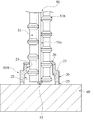
このようなスタッド溶接は、母材に対して鉄筋を突き当て溶接する場合によく用いられる。スタッドとしては、一様円形断面をもつ丸棒鋼のほか、鉄筋としてコンクリートに対する付着力を高めるために、図9に示すように、円柱の表面に軸線方向のリブおよび周方向の節とからなる突起bを形成した、いわゆる異形スタッドaが用いられる場合がある。 Such stud welding is often used when a reinforcing bar is abutted and welded to a base material. As a stud, in addition to a round steel bar having a uniform circular cross section, as shown in FIG. 9, a protrusion comprising an axial rib and a circumferential node on the surface of a cylinder in order to increase adhesion to concrete as a reinforcing bar. A so-called deformed stud a in which b is formed may be used.
この場合、フェルールcの上部開口dとこれを通るスタッドaとの間にできるだけすきまが生じないように、上記スタッドaには、図9に表れているように、その先端から、上記フェルールcの上部開口dを通過する可能性のある部位までの範囲において、上記の突起bを除去して使用するのが通例であった。その理由は、外部空気がフェルール内に侵入し、アーク放電による熱によって溶融している金属に空気が混入して生じるブローホールと呼ばれる溶接欠陥を防止するためである。 In this case, as much as possible the gap between the upper opening d and stud a therethrough ferrule c does not occur, the above-mentioned stud a, as appearing in FIG. 9, from the tip of the ferrule c In the range up to a portion that may pass through the upper opening d , it is usual to remove the projection b and use it. The reason for this is to prevent welding defects called blowholes, which are generated when external air enters the ferrule and air is mixed into the molten metal due to heat generated by arc discharge.
しかしながら、上記のような従来の異形スタッドを用いた溶接方法においては、異形棒鋼の所定範囲の突起を切除するという前工程が必要であるために、コスト上昇が避けられないという問題があった。また、異形棒鋼は、その一部のリブが除去された状態で母材に溶接されているため、鉄筋としての強度が長手方向について不均一となり、溶接部位において応力が集中してしまう溶接強度上の問題も潜在する。 However, in the welding method using the conventional deformed stud as described above, there is a problem that an increase in cost is inevitable because a pre-process of cutting a predetermined range of protrusions of the deformed steel bar is necessary. In addition, because the deformed steel bar is welded to the base metal with some ribs removed, the strength as a reinforcing bar becomes uneven in the longitudinal direction, and stress is concentrated in the welded part. The problem is also latent.
本願発明は、上記の事情のもとで考え出されたものであり、棒鋼の外周に突起を有する異形スタッドに対して突起を切除するといった前加工を必要とすることなしに、この異形スタッドを適正にスタッド溶接することがきるようにすることを課題とし、より具体的には、改良したフェルール、ならびにこの改良したフェルールを用いたスタッド溶接方法を提供し、あわせて、この方法に用いると好適な異形スタッドをも提供しようとするものである。 The present invention has been conceived under the above circumstances, and this deformed stud can be used without requiring a pre-processing such as cutting out the protrusion from the deformed stud having the protrusion on the outer periphery of the steel bar. It is an object to enable proper stud welding, and more specifically, an improved ferrule and a stud welding method using the improved ferrule are provided and are preferably used in this method. It is also intended to provide a specially shaped stud.
上記の課題を解決するため、本願発明では、次の技術的手段を採用している。 In order to solve the above problems, the present invention employs the following technical means.
本願発明の第1の側面に係るスタッド溶接用フェルールは、全体として軸方向両端が開口する筒状を呈するとともに、軸方向一端側にスタッド挿通孔を有し、軸方向他端側に上記スタッド挿通孔と連続する内部空間を備えるフェルール本体と、上記スタッド挿通孔の内方に向けてフランジ状に延出し、かつ外力によって変形可能な不燃性のシールド部を備え、上記シールド部は、全体としてドーナツ円板状をしたシールド部材を上記フェルール本体の軸方向一端側の端面に貼着することにより形成されていることを特徴としている。 The ferrule for stud welding according to the first aspect of the present invention has a cylindrical shape that is open at both ends in the axial direction as a whole, has a stud insertion hole at one axial end, and the stud insertion at the other axial end. a ferrule body having an inner space which is continuous with the hole extends in a flange shape toward the inside of the stud insertion hole, and includes a shield portion of the deformation can be non-flammable by the external force, the shield portion, the shielding member in the overall donut disc shape is characterized that you have been formed by attaching to the end face of the one axial end side of the ferrule body.
本発明の第1の側面に係るスタッド溶接用フェルールはまた、全体として軸方向両端が開口する筒状を呈するとともに、軸方向一端側にスタッド挿通孔を有し、軸方向他端側に上記スタッド挿通孔と連続する内部空間を備えるフェルール本体と、上記スタッド挿通孔の内方に向けてフランジ状に延出し、かつ外力によって変形可能な不燃性のシールド部を備え、上記フェルール本体は、上記スタッド挿通孔とこれより大径とした上記内部空間との境界に段部が形成されており、上記シールド部は、全体としてドーナツ円板状をしたシールド部材を上記段部に貼着することにより形成されていることをも特徴としている。 The stud welding ferrule according to the first aspect of the present invention also has a cylindrical shape that is open at both ends in the axial direction as a whole, has a stud insertion hole at one axial end, and the stud at the other axial end. A ferrule body having an internal space continuous with the insertion hole, and a nonflammable shield portion extending in a flange shape toward the inside of the stud insertion hole and deformable by an external force, and the ferrule body includes the stud A step portion is formed at the boundary between the insertion hole and the internal space having a larger diameter than the insertion hole, and the shield portion is formed by sticking a shield member having a donut disk shape as a whole to the step portion. It is also characterized by being .
このような構成のスタッド溶接用フェルールによれば、表面に縦方向のリブと横方向の節が形成されるなどの凹凸を有するスタッドを上記スタッド挿通孔に挿通した状態においても、上記シールド部が変形しつつ、スタッド挿通孔の内面とスタッドの表面との間のすきまを適度にシールドした状態を作り出すことができる。また、このシールド部は、不燃性を有しているので、スタッドと母材との間にアーク放電が起こり、スタッドの先端が溶融している高温状態においても、依然として上記のシールド状態を維持することができる。したがって、溶接操作中に上記スタッド挿通孔とスタッドとのすきまから外部空気がフェルール本体の内部に侵入することを好適に防止し、ブローホールなどの溶接欠陥の発生を防止することができる。 According to the stud welding ferrule having such a configuration, even when the stud having irregularities such as the formation of longitudinal ribs and lateral nodes on the surface is inserted into the stud insertion hole, the shield portion is While being deformed, it is possible to create a state in which the clearance between the inner surface of the stud insertion hole and the surface of the stud is appropriately shielded. Moreover, since this shield part has nonflammability, arc discharge occurs between the stud and the base material, and the above shield state is still maintained even in a high temperature state where the tip of the stud is melted. be able to. Therefore, it is possible to suitably prevent outside air from entering the ferrule body through the gap between the stud insertion hole and the stud during the welding operation, and to prevent occurrence of welding defects such as blow holes.
また、スタッドとして、表面に凹凸を残したままのものを使用することができるので、従来のように凹凸を除去するといった前加工が不要となり、コスト的にも有利となる。加えて、溶接後のスタッドの鉄筋としての強度低下を防止することもできる。 In addition, since the stud can be used with the unevenness left on the surface, a pre-processing such as removing the unevenness as in the prior art becomes unnecessary, which is advantageous in terms of cost. In addition, it is possible to prevent a decrease in strength as a reinforcing bar of the stud after welding.
好ましい実施の形態においてはまた、上記全体としてドーナツ円板状をしたシールド部材は、周方向について複数に分割されている。 In the preferred embodiment, the shield member in the donut-shaped as a whole above the circumferential direction that is divided into a plurality.
このような構成によれば、スタッド挿通孔に挿通されたスタッドの凹凸表面に対して上記シールド部材の先端がよりなじみやすく付着し、シールド効果を高めることができるほか、溶接操作終了後に行うフェルール本体の分割破砕の障害となることもない。 According to such a configuration, the tip of the shield member adheres more easily to the uneven surface of the stud inserted through the stud insertion hole, and the shielding effect can be enhanced. In addition, the ferrule body performed after the end of the welding operation It will not be an obstacle to splitting and crushing.
好ましい実施の形態においてはまた、上記フェルール本体の上記内部空間には、溶剤保持部材が嵌着されている。 In a preferred embodiment, a solvent holding member is fitted in the internal space of the ferrule body.
このような構成によれば、確実なアーク放電を惹起させることができる。 According to such a configuration, a reliable arc discharge can be caused.
本願発明の第2の側面に係るスタッド溶接方法は、上記本願発明の第1の側面に係るスタッド溶接用フェルールを用い、表面に凹凸を有するスタッドの先端を上記スタッド溶接用フェルールの上記スタッド挿通孔に挿通した状態で行うことを特徴としている。 The stud welding method according to the second aspect of the present invention uses the stud welding ferrule according to the first aspect of the present invention, and the stud insertion hole of the stud welding ferrule has an end of a stud having irregularities on the surface. It is characterized in that it is carried out in a state where it is inserted through.
このような構成によれば、本願発明の第1の側面について上述したのと同様の利点を享受することができる。 According to such a configuration, the same advantages as those described above for the first aspect of the present invention can be obtained.
本願発明の第3の側面に係るスタッドは、上記本願発明の第2の側面に係るスタッド溶接方法に用いるスタッドであって、棒状金属部材の表面に凹凸を有し、かつ、先端に溶剤が付着させられていることを特徴としている。 The stud according to the third aspect of the present invention is a stud used in the stud welding method according to the second aspect of the present invention, wherein the rod-shaped metal member has irregularities on the surface, and a solvent adheres to the tip. It is characterized by being allowed.
このようなスタッドを用いることにより、表面に凹凸を有するスタッドであっても、その先端に溶剤を付着させて用いるだけで、本願発明の第1の側面に係るスタッド溶接用フェルールと組み合わせて溶接操作することにより、ブローホールなどの溶接欠陥のない、適正な溶接を行うことができる。また、表面の凹凸を部分的に除去するといった前工程が不要となることも、前述したのと同様である。 By using such a stud, even if it is a stud having irregularities on the surface, a welding operation is performed in combination with the ferrule for stud welding according to the first aspect of the present invention simply by attaching a solvent to the tip of the stud. By doing so, it is possible to perform appropriate welding without welding defects such as blow holes. Further, as described above, it is not necessary to perform a previous step of partially removing the unevenness on the surface.
本願発明のその他の特徴および利点は、図面を参照して以下に行う詳細な説明から、より明らかとなろう。 Other features and advantages of the present invention will become more apparent from the detailed description given below with reference to the drawings.
以下、本願発明の好ましい実施の形態につき、図面を参照して具体的に説明する。 Hereinafter, a preferred embodiment of the present invention will be specifically described with reference to the drawings.
図1ないし図4は、本願発明に係るスタッド溶接用フェルール(以下、単にフェルールという。)の第1の実施形態を示している。 1 to 4 show a first embodiment of a stud welding ferrule (hereinafter simply referred to as a ferrule) according to the present invention.
このフェルール10Aは、全体として軸方向に貫通する筒状を呈しており、たとえば、MgO-Al2O3-SiO2系素地で形成されたセラミック成形物からなるフェルール本体20を備えている。このフェルール本体20は、その軸方向一端側の外径が軸方向他端側の外径よりも小となっている。軸方向一端側には、所定内径のスタッド挿通孔21が形成されており、軸方向他端側には、上記スタッド挿通孔21と連続する内部空間22が形成されている。この内部空間22の内径は、上記スタッド挿通孔21の内径より大であり、したがって、上記スタッド挿通孔21と上記内部空間22との境界には、段部23が形成されている。また、フェルール本体20の軸方向他端側の端面には、図3に良く表れているように、放射状に延びる複数の凹溝25が形成されている。
The
上記フェルール本体20の軸方向の一端側の端面には、ドーナツ円板状をしたシールド部材30が適当な接着部材を用いるなどして貼着されている。このシールド部材30は、たとえば炭素繊維などの不燃性繊維でできたクロスを複数枚重ねるなどして形成され、不燃性を有するとともに、外力によって容易に変形可能な部材である。実施形態では、このシールド部材30は、外径がほぼ上記フェルール本体20の軸方向一端側の外径と一致しており、内径は上記スタッド挿通孔21の内径より小となっている。そのため、このシールド部材30は、その内周側が上記スタッド挿通孔21の内面から内向フランジ状に延出させられる。
A
図に示す実施形態では、上記シールド部材30は、図2および図4に良く表れているように、内周側から複数のスリット31をいれるなどして、外力により、容易に複数に分離できるようにしてある。また、あらかじめ複数に分割したセグメントをフェルール本体20の端面に貼着してもよい。
In the embodiment shown in the figure, the
図1において、符号50は、上記構成のフェルール10Aと組み合わせて使用して溶接を行うスタッドを示す。このスタッド50は、丸棒ではなく、円柱の外周に軸方向に延びる膨出状のリブ51aと、周方向に延びる膨出状の節51bとを組み合わせた突起51を形成することにより、表面に凹凸が形成されたものである。このスタッド50は、上記のような突起51が形成された鉄筋部材を所定長さに切断したものであるが、母材60に対して溶接接続するべき先端部には、アルミニウムなどからなる溶剤55を付着させてある。
In FIG. 1, the code |
図1に表れているように、上記フェルール本体20のスタッド挿通孔21の内径は、上記スタッド50の最大外径、すなわち、上記突起51の頂部における外径と対応させ、突起51の頂部とスタッド挿通孔21の内面との間のすきまが必要最小限となるように設定される。また、上記ドーナツ円板状のシールド部材30の内径は、上記スタッド50の最小外径、すなわち、上記突起51が形成されていない部位の外径と対応させ、上記シールド部材30の半径方向内方の先端が上記スタッド50における突起51が形成されていない部位に対してわずかに離れるか、あるいはわずかに接触しうる程度に設定される。
As shown in FIG. 1, the inner diameter of the
上記構成のフェルール10Aおよびスタッド50を用いたスタッド溶接は、次のようにして行われる。
Stud welding using the
図1に示すように、上記フェルール10Aは、そのスタッド挿通孔21に上記スタッド50の先端が挿通されるようにして、スタッド50の先端に装着される。こうして上記フェルール10Aが装着されたスタッド50は、図示しないスタッド溶接機のチャックに装着される。スタッド溶接機を操作して上記スタッド50の先端を母材60に対して押し付けるようにし、スタッド溶接機を操作する。上記シールド部材30は、容易に変形可能であるから、スタッド50の先端に対する図1に示すようなフェルール10Aの装着状態を得ることができる。
As shown in FIG. 1, the ferrule 10 </ b> A is attached to the tip of the
上記フェルール10Aは、スタッド溶接機側の図示しないフェルール押し付けガイドによって、母材60に対して押し付けられた状態となる。この状態において、スタッド50はいったん所定距離母材60に対して引き上げられ、次いで、スタッド50と母材60との間に溶接電流が給電されると、スタッド50の先端と母材60との間にアーク放電が起こる。このアーク放電は、スタッド50の先端に溶剤55が付着させられていることにより、容易に起こる。この放電エネルギによってスタッド50の先端が溶融する。次いで、スタッド50に対する引き上げ力が解除され、スタッド溶接機側のばね弾力により、スタッド50には母材60に向けた押しつけ力が作用させられる。
The
やがて、溶融金属がフェルール10Aの内部空間22を満たすとともにやがて固化してゆくが、その過程では、アーク放電によって生じた高温ガスがフェルール10Aの内部を充満させる状態、あるいは、このような高温ガスと溶融金属が混じり合った状態が現出するが、このとき、上記したように、スタッド挿通孔21とスタッド50との間のすきまは、不燃性のシールド部材30によって適度にシールドされた状態が維持される。したがって、フェルール10Aのスタッド挿通孔21から外部空気がフェルール10Aの内部に侵入することが適正に防止され、母材60に対するスタッド50の溶接部位にブローホールなどの溶接欠陥が生じることを効果的に防止することができる。
Eventually, the molten metal slide into eventually solidified with filling the
上記のように溶融金属がフェルール10A内で固化した後、上記フェルール10Aはハンマで打ち砕くなどして破砕され、除去されるが、上記したようにシールド部材30にはスリット31を入れるなどして容易に分離可能となっているので、フェルール10Aの破砕と同時に分離する。したがって、このシールド部材30がフェルール10Aの破砕除去の障害となるということはない。
After the molten metal as described above is solidified in the
また、スタッド50は、表面に凹凸を有しているが、従来のように先端部位の凹凸を切除する前工程が不要であるため、コスト的に有利となる。
Moreover, although the
さらに、スタッド50は、表面の凹凸をその全長にわたって残したまま適正に母材60に対して突き当て溶接されるので、溶接部位に応力が集中するといったことを緩和することができ、鉄筋としての強度保持にも有効となる。
Furthermore, since the
図5は、本願発明に係るフェルールの第2の実施形態を示している。このフェルール10Bは、ドーナツ円板状のシールド部材30がフェルール本体20における上記段部23に貼着されている点を除き、第1の実施形態に係るフェルール10Aと同様であるので、同一の部位に第1の実施形態と同一の符号を付して詳細な説明を省略する。
FIG. 5 shows a second embodiment of the ferrule according to the present invention. Since this
この第2の実施形態に係るフェルール10Bにおいても、フェルール本体20の内部に、上記シールド部材30の内周側の部位が内向フランジ状に延出することになるので、溶接時、外部空気がフェルール本体20内部に侵入することを有効に防止することができることのほか、第1の実施形態について上述したのと同様の利点を享受することができる。
Also in the
図6は、本願発明に係るフェルールの第3の実施形態を示している。このフェルール10Cにおいては、図1ないし図4に示した第1の実施形態に係るフェルール10Aに、鉄系金属の薄板部材の一面側膨出部の中央にアルミニウムなどの溶剤を付着してなる溶剤保持部材40を付加した構成を備えている。その余の構成については、第1の実施形態に係るフェルール10Aと同一であるので、該当個所に同一の符号を付して説明を省略する。
FIG. 6 shows a third embodiment of the ferrule according to the present invention. In this
上記溶剤保持部材40は、図7に良く表れているように、全体として略矩形の薄板部材
41の中央部をドーム状に膨出させ、この膨出部43の頂部付近に溶剤45を付着させたものである。薄板部材41の4つの角部42は、ばね性をもって折り立てられており、この折り立て部にフェルール本体20の内部空間22の内壁が弾力をもって外接するように構成されている。
As shown in FIG. 7, the solvent holding
上記溶剤保持部材40は、図6に示すように、膨出側が外部に臨むようにして、フェルール本体20の内部空間22に装着する。そうすると、この溶剤保持部材40は、上記のように4つの角部42が内部空間22の内壁に弾接することによってフェルール本体20の内部に保持される。
As shown in FIG. 6 , the solvent holding
この第3の実施形態に係るフェルール10Cを用いてスタッド溶接をする場合、図6に表れているように、スタッド50としては、表面に凹凸を有する棒鋼を切断したものがそのまま用いられる。すなわち、図1に示した場合のように、先端に溶剤55を付着させておく必要はない。
In the case of performing stud welding using the
この第3の実施形態に係るフェルール10Cを用いてスタッド溶接をするには、図6に示すように、スタッド50の先端に上記フェルール10Cを嵌着した状態において、第1の実施形態について上述したのと同様の操作により、スタッド溶接機による溶接操作をする。アーク放電は、上記した溶剤保持部材40の溶剤45によって確実に誘起させられ、これによって溶剤保持部材40の金属薄板部材ないしスタッド50の先端部分が溶融する。このような溶接過程において、外部空気のフェルール内への流入がシールド部材30によって防止される点は、第1の実施形態について上述したのと同様である。また、この第3の実施形態に係るフェルール10Cについても、第1の実施形態について上述したのと同様の利点を享受できることは、詳細な説明を繰り返すまでもなく、明らかであろう。
In order to perform stud welding using the
なお、この第3の実施形態に係るフェルール10Cによれば、スタッド50の先端に溶剤55を付着させておく工程が不要となるという利点がある。
Note that the ferrule 10 </ b> C according to the third embodiment has an advantage that a step of attaching the solvent 55 to the tip of the
図8は、本願発明に係るフェルールの第4の実施形態を示している。このフェルール10Dは、第2の実施形態に係るフェルール10B(図5)に、第3の実施形態について上述したのと同様の溶剤保持部材40を付加したものである。このフェルール10Dを用いたスタッド溶接は、第3の実施形態について上述したのと同様に行うことができる。そうして、この第4の実施形態についても、第3の実施形態と同様の利点を享受することができる。
FIG. 8 shows a fourth embodiment of the ferrule according to the present invention. This
もちろん、この発明の範囲は上述した各実施形態の構成に限定されることはなく、各請求項に記載した事項の範囲内でのあらゆる変更は、すべて本願発明の範囲に含まれる。 Of course, the scope of the present invention is not limited to the configurations of the above-described embodiments, and all modifications within the scope of the matters described in the claims are all included in the scope of the present invention.
フェルール本体20の具体的な形状、大きさは、使用するスタッド50の径に応じて適宜変更すればよいのである。また、シールド部材30についても、不燃性を有していて、容易に変形可能な材質であれば、どのようなものを採用しても差し支えない。要は、フェルール本体20におけるスタッド挿通孔21と、表面に凹凸を有するいわゆる異形スタッド50の表面とのすきまを、凹凸に応じて封鎖することができればよいのである。
What is necessary is just to change suitably the specific shape and magnitude | size of the ferrule
10A,10B,10C,10D フェルール
20 フェルール本体
21 スタッド挿通孔
22 内部空間
23 段部
25 凹溝
30 シールド部材
31 スリット
40 溶剤保持部材
41 板材
42 角部
43 膨出部
45 溶剤
50 スタッド
51 突起
55 溶剤
60 母材
10A, 10B, 10C,
Claims (7)
上記スタッド挿通孔の内方に向けてフランジ状に延出し、かつ外力によって変形可能な不燃性のシールド部を備え、
上記シールド部は、全体としてドーナツ円板状をしたシールド部材を上記フェルール本体の軸方向一端側の端面に貼着することにより形成されていることを特徴とする、スタッド溶接用フェルール。 A ferrule body having a cylindrical shape with both axial ends open as a whole, a stud insertion hole on one axial end side, and an internal space continuous with the stud insertion hole on the other axial end side;
Extending flange toward the inside of the stud insertion hole, and includes a shield portion of the deformation can be non-flammable by an external force,
The shield portion, the shield member in the donut-shaped, characterized that you have been formed by attaching to the end face of the one axial end side of the ferrule body as a whole, ferrule stud welding.
上記スタッド挿通孔の内方に向けてフランジ状に延出し、かつ外力によって変形可能な不燃性のシールド部を備え、
上記フェルール本体は、上記スタッド挿通孔とこれより大径とした上記内部空間との境界に段部が形成されており、上記シールド部は、全体としてドーナツ円板状をしたシールド部材を上記段部に貼着することにより形成されていることを特徴とする、スタッド溶接用フェルール。 A ferrule body having a cylindrical shape with both axial ends open as a whole, a stud insertion hole on one axial end side, and an internal space continuous with the stud insertion hole on the other axial end side;
A nonflammable shield part that extends in a flange shape toward the inside of the stud insertion hole and can be deformed by an external force,
The ferrule body has a step formed at the boundary between the stud insertion hole and the inner space having a larger diameter than the stud insertion hole, and the shield part is formed by connecting the shield member having a donut disk shape as a whole to the step part. A ferrule for stud welding , which is formed by sticking to a stud.
Priority Applications (1)
| Application Number | Priority Date | Filing Date | Title |
|---|---|---|---|
| JP2006149807A JP5129460B2 (en) | 2006-05-30 | 2006-05-30 | Stud, ferrule and welding method using them |
Applications Claiming Priority (1)
| Application Number | Priority Date | Filing Date | Title |
|---|---|---|---|
| JP2006149807A JP5129460B2 (en) | 2006-05-30 | 2006-05-30 | Stud, ferrule and welding method using them |
Publications (3)
| Publication Number | Publication Date |
|---|---|
| JP2007319868A JP2007319868A (en) | 2007-12-13 |
| JP2007319868A5 JP2007319868A5 (en) | 2009-05-21 |
| JP5129460B2 true JP5129460B2 (en) | 2013-01-30 |
Family
ID=38853094
Family Applications (1)
| Application Number | Title | Priority Date | Filing Date |
|---|---|---|---|
| JP2006149807A Active JP5129460B2 (en) | 2006-05-30 | 2006-05-30 | Stud, ferrule and welding method using them |
Country Status (1)
| Country | Link |
|---|---|
| JP (1) | JP5129460B2 (en) |
Families Citing this family (3)
| Publication number | Priority date | Publication date | Assignee | Title |
|---|---|---|---|---|
| JP6045823B2 (en) * | 2012-06-28 | 2016-12-14 | 共英製鋼株式会社 | Manufacturing method of reinforcing steel bars used for stud welding |
| JP6242836B2 (en) * | 2015-04-01 | 2017-12-06 | 日本スタッドウェルディング株式会社 | Stud welding method |
| KR20240052188A (en) * | 2022-10-14 | 2024-04-23 | 박찬석 | Welded reinforcement couplers and fastening methods |
Family Cites Families (2)
| Publication number | Priority date | Publication date | Assignee | Title |
|---|---|---|---|---|
| JPH09262677A (en) * | 1996-03-28 | 1997-10-07 | Negishi Kogyo:Kk | Arc shield provided with cylindrical discharge melting member |
| JP3690403B2 (en) * | 2003-04-22 | 2005-08-31 | 株式会社竹中工務店 | Installation method of arc starter in arc stud welding method |
-
2006
- 2006-05-30 JP JP2006149807A patent/JP5129460B2/en active Active
Also Published As
| Publication number | Publication date |
|---|---|
| JP2007319868A (en) | 2007-12-13 |
Similar Documents
| Publication | Publication Date | Title |
|---|---|---|
| JP4052545B2 (en) | Method for forming a coupling by pressing a mounting member and a tube end inserted into a tube holding portion of the mounting member, and a shaped part therefor | |
| JP5129460B2 (en) | Stud, ferrule and welding method using them | |
| KR101690341B1 (en) | Compressed air tank for utility vehicles and method of manufacture | |
| JP4624360B2 (en) | Feeder element for metal casting | |
| CA2378412C (en) | Weld nut | |
| JP2007319868A5 (en) | ||
| US9616520B2 (en) | Friction stir welding member | |
| JP2010207850A (en) | Welding joining member and welding joining method | |
| EP0480034A1 (en) | Plasma torch | |
| JP5291516B2 (en) | Damper fixing jig and manufacturing method thereof | |
| KR20100113305A (en) | Method for manufacturing flange | |
| JP2007190592A (en) | Welding method using silver braze | |
| JP6242836B2 (en) | Stud welding method | |
| JPH11277153A (en) | Formation of constriction to cylindrical member | |
| JPH0357350Y2 (en) | ||
| JP6730839B2 (en) | Gas blowing plug | |
| JP2010142876A (en) | Welding supporter having arc generating piece | |
| JP5613539B2 (en) | Mold structure | |
| JP2002168348A (en) | O-ring structure | |
| KR101969737B1 (en) | Back bead prevention device of yoke | |
| JP2008198558A (en) | Assembly structure of fuse element in electric wire fuse | |
| JP4292852B2 (en) | gasket | |
| JP3918130B2 (en) | Hydraulic cylinder | |
| JPS595074B2 (en) | Stud welding ferrule | |
| KR100452258B1 (en) | A structure for fixing core with mold |
Legal Events
| Date | Code | Title | Description |
|---|---|---|---|
| A521 | Request for written amendment filed |
Free format text: JAPANESE INTERMEDIATE CODE: A523 Effective date: 20090403 |
|
| A621 | Written request for application examination |
Free format text: JAPANESE INTERMEDIATE CODE: A621 Effective date: 20090403 |
|
| A977 | Report on retrieval |
Free format text: JAPANESE INTERMEDIATE CODE: A971007 Effective date: 20110516 |
|
| A131 | Notification of reasons for refusal |
Free format text: JAPANESE INTERMEDIATE CODE: A131 Effective date: 20110524 |
|
| A521 | Request for written amendment filed |
Free format text: JAPANESE INTERMEDIATE CODE: A523 Effective date: 20110721 |
|
| A131 | Notification of reasons for refusal |
Free format text: JAPANESE INTERMEDIATE CODE: A131 Effective date: 20120117 |
|
| A521 | Request for written amendment filed |
Free format text: JAPANESE INTERMEDIATE CODE: A523 Effective date: 20120315 |
|
| A131 | Notification of reasons for refusal |
Free format text: JAPANESE INTERMEDIATE CODE: A131 Effective date: 20120710 |
|
| A521 | Request for written amendment filed |
Free format text: JAPANESE INTERMEDIATE CODE: A523 Effective date: 20120718 |
|
| TRDD | Decision of grant or rejection written | ||
| A01 | Written decision to grant a patent or to grant a registration (utility model) |
Free format text: JAPANESE INTERMEDIATE CODE: A01 Effective date: 20121030 |
|
| A01 | Written decision to grant a patent or to grant a registration (utility model) |
Free format text: JAPANESE INTERMEDIATE CODE: A01 |
|
| A61 | First payment of annual fees (during grant procedure) |
Free format text: JAPANESE INTERMEDIATE CODE: A61 Effective date: 20121102 |
|
| R150 | Certificate of patent or registration of utility model |
Free format text: JAPANESE INTERMEDIATE CODE: R150 Ref document number: 5129460 Country of ref document: JP Free format text: JAPANESE INTERMEDIATE CODE: R150 |
|
| FPAY | Renewal fee payment (event date is renewal date of database) |
Free format text: PAYMENT UNTIL: 20151109 Year of fee payment: 3 |
|
| R250 | Receipt of annual fees |
Free format text: JAPANESE INTERMEDIATE CODE: R250 |
|
| R250 | Receipt of annual fees |
Free format text: JAPANESE INTERMEDIATE CODE: R250 |
|
| R250 | Receipt of annual fees |
Free format text: JAPANESE INTERMEDIATE CODE: R250 |
|
| R250 | Receipt of annual fees |
Free format text: JAPANESE INTERMEDIATE CODE: R250 |
|
| R250 | Receipt of annual fees |
Free format text: JAPANESE INTERMEDIATE CODE: R250 |
|
| R250 | Receipt of annual fees |
Free format text: JAPANESE INTERMEDIATE CODE: R250 |
|
| R250 | Receipt of annual fees |
Free format text: JAPANESE INTERMEDIATE CODE: R250 |