JP5129324B2 - Method for blocking lens blanks, adhesive formulations and use of adhesive formulations in lens blocking - Google Patents
Method for blocking lens blanks, adhesive formulations and use of adhesive formulations in lens blocking Download PDFInfo
- Publication number
- JP5129324B2 JP5129324B2 JP2010513768A JP2010513768A JP5129324B2 JP 5129324 B2 JP5129324 B2 JP 5129324B2 JP 2010513768 A JP2010513768 A JP 2010513768A JP 2010513768 A JP2010513768 A JP 2010513768A JP 5129324 B2 JP5129324 B2 JP 5129324B2
- Authority
- JP
- Japan
- Prior art keywords
- lens
- block
- adhesive
- blocking
- filler
- Prior art date
- Legal status (The legal status is an assumption and is not a legal conclusion. Google has not performed a legal analysis and makes no representation as to the accuracy of the status listed.)
- Active
Links
- 230000001070 adhesive effect Effects 0.000 title claims abstract description 192
- 239000000853 adhesive Substances 0.000 title claims abstract description 191
- 230000000903 blocking effect Effects 0.000 title claims abstract description 145
- 239000000203 mixture Substances 0.000 title claims abstract description 140
- 238000000034 method Methods 0.000 title claims abstract description 65
- 238000009472 formulation Methods 0.000 title claims description 108
- 239000000463 material Substances 0.000 claims abstract description 137
- 239000000945 filler Substances 0.000 claims abstract description 99
- 239000007787 solid Substances 0.000 claims abstract description 38
- 238000006116 polymerization reaction Methods 0.000 claims abstract description 19
- 230000000379 polymerizing effect Effects 0.000 claims abstract description 4
- 239000002245 particle Substances 0.000 claims description 42
- 239000007788 liquid Substances 0.000 claims description 37
- 238000002156 mixing Methods 0.000 claims description 29
- 229920005989 resin Polymers 0.000 claims description 25
- 239000011347 resin Substances 0.000 claims description 25
- 230000008859 change Effects 0.000 claims description 19
- SOGAXMICEFXMKE-UHFFFAOYSA-N Butylmethacrylate Chemical compound CCCCOC(=O)C(C)=C SOGAXMICEFXMKE-UHFFFAOYSA-N 0.000 claims description 14
- 239000000835 fiber Substances 0.000 claims description 13
- PAPBSGBWRJIAAV-UHFFFAOYSA-N ε-Caprolactone Chemical compound O=C1CCCCCO1 PAPBSGBWRJIAAV-UHFFFAOYSA-N 0.000 claims description 13
- 238000009826 distribution Methods 0.000 claims description 8
- 239000004698 Polyethylene Substances 0.000 claims description 7
- 229920003145 methacrylic acid copolymer Polymers 0.000 claims description 7
- 229940117841 methacrylic acid copolymer Drugs 0.000 claims description 7
- 229920000573 polyethylene Polymers 0.000 claims description 7
- 238000010521 absorption reaction Methods 0.000 claims description 6
- 229910052782 aluminium Inorganic materials 0.000 claims description 6
- XAGFODPZIPBFFR-UHFFFAOYSA-N aluminium Chemical compound [Al] XAGFODPZIPBFFR-UHFFFAOYSA-N 0.000 claims description 6
- 239000008187 granular material Substances 0.000 claims description 6
- 230000020169 heat generation Effects 0.000 claims description 6
- CERQOIWHTDAKMF-UHFFFAOYSA-M Methacrylate Chemical compound CC(=C)C([O-])=O CERQOIWHTDAKMF-UHFFFAOYSA-M 0.000 claims description 5
- SUPCQIBBMFXVTL-UHFFFAOYSA-N ethyl 2-methylprop-2-enoate Chemical compound CCOC(=O)C(C)=C SUPCQIBBMFXVTL-UHFFFAOYSA-N 0.000 claims description 5
- 229910052751 metal Inorganic materials 0.000 claims description 5
- 239000002184 metal Substances 0.000 claims description 5
- 125000002496 methyl group Chemical group [H]C([H])([H])* 0.000 claims description 5
- 239000004417 polycarbonate Substances 0.000 claims description 5
- 229920000515 polycarbonate Polymers 0.000 claims description 5
- 229920001897 terpolymer Polymers 0.000 claims description 5
- NIXOWILDQLNWCW-UHFFFAOYSA-N 2-Propenoic acid Natural products OC(=O)C=C NIXOWILDQLNWCW-UHFFFAOYSA-N 0.000 claims description 4
- 230000009477 glass transition Effects 0.000 claims description 4
- 239000000843 powder Substances 0.000 claims description 4
- FYZUENZXIZCLAZ-UHFFFAOYSA-N 2-methylhept-2-enoic acid Chemical compound CCCCC=C(C)C(O)=O FYZUENZXIZCLAZ-UHFFFAOYSA-N 0.000 claims description 3
- 239000004033 plastic Substances 0.000 claims description 3
- 229920003023 plastic Polymers 0.000 claims description 3
- -1 polyethylene Polymers 0.000 claims description 3
- 239000002952 polymeric resin Substances 0.000 claims 1
- 229920003002 synthetic resin Polymers 0.000 claims 1
- 230000005855 radiation Effects 0.000 abstract description 12
- 239000002861 polymer material Substances 0.000 abstract description 2
- 238000001429 visible spectrum Methods 0.000 description 31
- 238000002211 ultraviolet spectrum Methods 0.000 description 27
- 238000012545 processing Methods 0.000 description 18
- 238000001723 curing Methods 0.000 description 16
- 150000001875 compounds Chemical class 0.000 description 14
- 230000000694 effects Effects 0.000 description 13
- 230000008569 process Effects 0.000 description 13
- 230000035882 stress Effects 0.000 description 10
- 230000008901 benefit Effects 0.000 description 8
- 238000010438 heat treatment Methods 0.000 description 7
- 230000001788 irregular Effects 0.000 description 7
- 238000013459 approach Methods 0.000 description 6
- 238000000227 grinding Methods 0.000 description 6
- 238000003384 imaging method Methods 0.000 description 6
- 238000003754 machining Methods 0.000 description 6
- 238000004519 manufacturing process Methods 0.000 description 6
- 239000000126 substance Substances 0.000 description 6
- 230000032798 delamination Effects 0.000 description 5
- 230000001965 increasing effect Effects 0.000 description 5
- 238000005086 pumping Methods 0.000 description 5
- 238000006243 chemical reaction Methods 0.000 description 4
- 238000005520 cutting process Methods 0.000 description 4
- 238000010586 diagram Methods 0.000 description 4
- 239000002904 solvent Substances 0.000 description 4
- 239000011230 binding agent Substances 0.000 description 3
- 230000015572 biosynthetic process Effects 0.000 description 3
- 230000005670 electromagnetic radiation Effects 0.000 description 3
- 239000011159 matrix material Substances 0.000 description 3
- 238000010943 off-gassing Methods 0.000 description 3
- 230000003287 optical effect Effects 0.000 description 3
- 238000005498 polishing Methods 0.000 description 3
- 239000000047 product Substances 0.000 description 3
- 239000001993 wax Substances 0.000 description 3
- SMZOUWXMTYCWNB-UHFFFAOYSA-N 2-(2-methoxy-5-methylphenyl)ethanamine Chemical compound COC1=CC=C(C)C=C1CCN SMZOUWXMTYCWNB-UHFFFAOYSA-N 0.000 description 2
- 229920005479 Lucite® Polymers 0.000 description 2
- FAIIFDPAEUKBEP-UHFFFAOYSA-N Nilvadipine Chemical compound COC(=O)C1=C(C#N)NC(C)=C(C(=O)OC(C)C)C1C1=CC=CC([N+]([O-])=O)=C1 FAIIFDPAEUKBEP-UHFFFAOYSA-N 0.000 description 2
- 239000011324 bead Substances 0.000 description 2
- 238000005452 bending Methods 0.000 description 2
- 229920006026 co-polymeric resin Polymers 0.000 description 2
- 238000000576 coating method Methods 0.000 description 2
- 230000008602 contraction Effects 0.000 description 2
- 238000007796 conventional method Methods 0.000 description 2
- 229920001577 copolymer Polymers 0.000 description 2
- 238000013461 design Methods 0.000 description 2
- 238000011161 development Methods 0.000 description 2
- 230000018109 developmental process Effects 0.000 description 2
- 238000009792 diffusion process Methods 0.000 description 2
- 230000007613 environmental effect Effects 0.000 description 2
- 238000011049 filling Methods 0.000 description 2
- 238000009501 film coating Methods 0.000 description 2
- 239000012530 fluid Substances 0.000 description 2
- 230000004927 fusion Effects 0.000 description 2
- 230000006698 induction Effects 0.000 description 2
- 238000005259 measurement Methods 0.000 description 2
- 229910001092 metal group alloy Inorganic materials 0.000 description 2
- 238000005459 micromachining Methods 0.000 description 2
- 239000012768 molten material Substances 0.000 description 2
- 239000000178 monomer Substances 0.000 description 2
- 229920000642 polymer Polymers 0.000 description 2
- 239000004926 polymethyl methacrylate Substances 0.000 description 2
- 230000001681 protective effect Effects 0.000 description 2
- 238000004381 surface treatment Methods 0.000 description 2
- 229920001169 thermoplastic Polymers 0.000 description 2
- 239000004416 thermosoftening plastic Substances 0.000 description 2
- 239000010409 thin film Substances 0.000 description 2
- 239000012855 volatile organic compound Substances 0.000 description 2
- XLYOFNOQVPJJNP-UHFFFAOYSA-N water Substances O XLYOFNOQVPJJNP-UHFFFAOYSA-N 0.000 description 2
- KIQNOXFYOCZBMH-UHFFFAOYSA-N 2-methylpent-2-enoic acid prop-2-enoic acid Chemical compound C(C=C)(=O)O.C(C)C=C(C(=O)O)C KIQNOXFYOCZBMH-UHFFFAOYSA-N 0.000 description 1
- OKTJSMMVPCPJKN-UHFFFAOYSA-N Carbon Chemical compound [C] OKTJSMMVPCPJKN-UHFFFAOYSA-N 0.000 description 1
- CERQOIWHTDAKMF-UHFFFAOYSA-N Methacrylic acid Chemical compound CC(=C)C(O)=O CERQOIWHTDAKMF-UHFFFAOYSA-N 0.000 description 1
- 229920006397 acrylic thermoplastic Polymers 0.000 description 1
- 239000006117 anti-reflective coating Substances 0.000 description 1
- 230000009286 beneficial effect Effects 0.000 description 1
- 230000005540 biological transmission Effects 0.000 description 1
- 229910052799 carbon Inorganic materials 0.000 description 1
- 230000001364 causal effect Effects 0.000 description 1
- 239000003795 chemical substances by application Substances 0.000 description 1
- 238000004140 cleaning Methods 0.000 description 1
- 239000011248 coating agent Substances 0.000 description 1
- 230000001427 coherent effect Effects 0.000 description 1
- 230000002301 combined effect Effects 0.000 description 1
- 238000004891 communication Methods 0.000 description 1
- 238000011109 contamination Methods 0.000 description 1
- 230000008878 coupling Effects 0.000 description 1
- 238000010168 coupling process Methods 0.000 description 1
- 238000005859 coupling reaction Methods 0.000 description 1
- 230000003247 decreasing effect Effects 0.000 description 1
- 230000001419 dependent effect Effects 0.000 description 1
- 229910003460 diamond Inorganic materials 0.000 description 1
- 239000010432 diamond Substances 0.000 description 1
- 238000007516 diamond turning Methods 0.000 description 1
- 238000005516 engineering process Methods 0.000 description 1
- 125000001495 ethyl group Chemical group [H]C([H])([H])C([H])([H])* 0.000 description 1
- 239000010408 film Substances 0.000 description 1
- 239000012767 functional filler Substances 0.000 description 1
- 239000011521 glass Substances 0.000 description 1
- 230000001939 inductive effect Effects 0.000 description 1
- 229910052500 inorganic mineral Inorganic materials 0.000 description 1
- 239000004922 lacquer Substances 0.000 description 1
- 238000000691 measurement method Methods 0.000 description 1
- 230000007246 mechanism Effects 0.000 description 1
- 239000002923 metal particle Substances 0.000 description 1
- 238000003801 milling Methods 0.000 description 1
- 239000011707 mineral Substances 0.000 description 1
- 238000012544 monitoring process Methods 0.000 description 1
- 238000012856 packing Methods 0.000 description 1
- 239000003973 paint Substances 0.000 description 1
- 239000008188 pellet Substances 0.000 description 1
- 229920003229 poly(methyl methacrylate) Polymers 0.000 description 1
- 229920001610 polycaprolactone Polymers 0.000 description 1
- 239000004632 polycaprolactone Substances 0.000 description 1
- 238000002203 pretreatment Methods 0.000 description 1
- 238000000746 purification Methods 0.000 description 1
- 238000003908 quality control method Methods 0.000 description 1
- 230000009467 reduction Effects 0.000 description 1
- 239000004065 semiconductor Substances 0.000 description 1
- 239000011265 semifinished product Substances 0.000 description 1
- ISXSCDLOGDJUNJ-UHFFFAOYSA-N tert-butyl prop-2-enoate Chemical compound CC(C)(C)OC(=O)C=C ISXSCDLOGDJUNJ-UHFFFAOYSA-N 0.000 description 1
- 238000012360 testing method Methods 0.000 description 1
- 230000008646 thermal stress Effects 0.000 description 1
- 229910052724 xenon Inorganic materials 0.000 description 1
- FHNFHKCVQCLJFQ-UHFFFAOYSA-N xenon atom Chemical compound [Xe] FHNFHKCVQCLJFQ-UHFFFAOYSA-N 0.000 description 1
Images


Classifications
-
- B—PERFORMING OPERATIONS; TRANSPORTING
- B24—GRINDING; POLISHING
- B24B—MACHINES, DEVICES, OR PROCESSES FOR GRINDING OR POLISHING; DRESSING OR CONDITIONING OF ABRADING SURFACES; FEEDING OF GRINDING, POLISHING, OR LAPPING AGENTS
- B24B13/00—Machines or devices designed for grinding or polishing optical surfaces on lenses or surfaces of similar shape on other work; Accessories therefor
- B24B13/005—Blocking means, chucks or the like; Alignment devices
- B24B13/0057—Deblocking of lenses
-
- B—PERFORMING OPERATIONS; TRANSPORTING
- B29—WORKING OF PLASTICS; WORKING OF SUBSTANCES IN A PLASTIC STATE IN GENERAL
- B29D—PRODUCING PARTICULAR ARTICLES FROM PLASTICS OR FROM SUBSTANCES IN A PLASTIC STATE
- B29D11/00—Producing optical elements, e.g. lenses or prisms
- B29D11/00009—Production of simple or compound lenses
- B29D11/00423—Plants for the production of simple or compound lenses
-
- B—PERFORMING OPERATIONS; TRANSPORTING
- B29—WORKING OF PLASTICS; WORKING OF SUBSTANCES IN A PLASTIC STATE IN GENERAL
- B29D—PRODUCING PARTICULAR ARTICLES FROM PLASTICS OR FROM SUBSTANCES IN A PLASTIC STATE
- B29D11/00—Producing optical elements, e.g. lenses or prisms
- B29D11/00932—Combined cutting and grinding thereof
- B29D11/00942—Combined cutting and grinding thereof where the lens material is mounted in a support for mounting onto a cutting device, e.g. a lathe, and where the support is of machinable material, e.g. plastics
-
- C—CHEMISTRY; METALLURGY
- C09—DYES; PAINTS; POLISHES; NATURAL RESINS; ADHESIVES; COMPOSITIONS NOT OTHERWISE PROVIDED FOR; APPLICATIONS OF MATERIALS NOT OTHERWISE PROVIDED FOR
- C09J—ADHESIVES; NON-MECHANICAL ASPECTS OF ADHESIVE PROCESSES IN GENERAL; ADHESIVE PROCESSES NOT PROVIDED FOR ELSEWHERE; USE OF MATERIALS AS ADHESIVES
- C09J133/00—Adhesives based on homopolymers or copolymers of compounds having one or more unsaturated aliphatic radicals, each having only one carbon-to-carbon double bond, and at least one being terminated by only one carboxyl radical, or of salts, anhydrides, esters, amides, imides, or nitriles thereof; Adhesives based on derivatives of such polymers
- C09J133/04—Homopolymers or copolymers of esters
- C09J133/06—Homopolymers or copolymers of esters of esters containing only carbon, hydrogen and oxygen, the oxygen atom being present only as part of the carboxyl radical
- C09J133/10—Homopolymers or copolymers of methacrylic acid esters
- C09J133/12—Homopolymers or copolymers of methyl methacrylate
-
- C—CHEMISTRY; METALLURGY
- C08—ORGANIC MACROMOLECULAR COMPOUNDS; THEIR PREPARATION OR CHEMICAL WORKING-UP; COMPOSITIONS BASED THEREON
- C08L—COMPOSITIONS OF MACROMOLECULAR COMPOUNDS
- C08L2666/00—Composition of polymers characterized by a further compound in the blend, being organic macromolecular compounds, natural resins, waxes or and bituminous materials, non-macromolecular organic substances, inorganic substances or characterized by their function in the composition
- C08L2666/02—Organic macromolecular compounds, natural resins, waxes or and bituminous materials
-
- C—CHEMISTRY; METALLURGY
- C08—ORGANIC MACROMOLECULAR COMPOUNDS; THEIR PREPARATION OR CHEMICAL WORKING-UP; COMPOSITIONS BASED THEREON
- C08L—COMPOSITIONS OF MACROMOLECULAR COMPOUNDS
- C08L33/00—Compositions of homopolymers or copolymers of compounds having one or more unsaturated aliphatic radicals, each having only one carbon-to-carbon double bond, and only one being terminated by only one carboxyl radical, or of salts, anhydrides, esters, amides, imides or nitriles thereof; Compositions of derivatives of such polymers
- C08L33/04—Homopolymers or copolymers of esters
- C08L33/06—Homopolymers or copolymers of esters of esters containing only carbon, hydrogen and oxygen, which oxygen atoms are present only as part of the carboxyl radical
- C08L33/08—Homopolymers or copolymers of acrylic acid esters
-
- C—CHEMISTRY; METALLURGY
- C08—ORGANIC MACROMOLECULAR COMPOUNDS; THEIR PREPARATION OR CHEMICAL WORKING-UP; COMPOSITIONS BASED THEREON
- C08L—COMPOSITIONS OF MACROMOLECULAR COMPOUNDS
- C08L33/00—Compositions of homopolymers or copolymers of compounds having one or more unsaturated aliphatic radicals, each having only one carbon-to-carbon double bond, and only one being terminated by only one carboxyl radical, or of salts, anhydrides, esters, amides, imides or nitriles thereof; Compositions of derivatives of such polymers
- C08L33/04—Homopolymers or copolymers of esters
- C08L33/06—Homopolymers or copolymers of esters of esters containing only carbon, hydrogen and oxygen, which oxygen atoms are present only as part of the carboxyl radical
- C08L33/10—Homopolymers or copolymers of methacrylic acid esters
- C08L33/12—Homopolymers or copolymers of methyl methacrylate
Abstract
Description
本発明は、一般的に、レンズ形成処理中に、処方作業場(prescription workshop)で、即ち、処方箋に従って通例の材料(ポリカーボネート、鉱物ガラス、CR39、HIインデックスなど)から個々のメガネレンズを製造するための生産作業場で、大衆に利用されるような、眼用レンズブランクとこのレンズブランクを支持するためのレンズ支持ブロック(レンズブロック)との結合に関する。 The present invention generally provides for the production of individual eyeglass lenses from a customary material (polycarbonate, mineral glass, CR39, HI index, etc.) during a lens formation process in a prescription workshop, ie according to a prescription. The present invention relates to a combination of an ophthalmic lens blank and a lens support block (lens block) for supporting the lens blank, which is used by the general public in the production workplace of the present invention.
特に、本発明は、レンズブランクをブロッキングするための方法、レンズブロッキングにおける接着剤配合物(adhesive composition)の使用及び接着剤配合物自体に関する。本発明では、放射線硬化材料が、各場合において結合剤として使用される。本出願の文脈において、「放射線硬化材料」は、所定の電磁放射波長に対して化学的に感受性を有する液体化学樹脂化合物を示している。この液体化学樹脂化合物は、樹脂を硬化させる、即ち、材料がこれらの「光活性(photo active)」波を照射されたとき、固体となるように重合する。言い換えれば、この材料は、このような電磁放射に、特に、紫外線(UV)及び高可視スペクトル(VIS)の光に晒されて、液体から固体へと相変化する。 In particular, the invention relates to a method for blocking a lens blank, the use of an adhesive composition in lens blocking and the adhesive formulation itself. In the present invention, a radiation curable material is used as a binder in each case. In the context of this application, “radiation curable material” refers to a liquid chemical resin compound that is chemically sensitive to a given electromagnetic radiation wavelength. The liquid chemical resin compound cures the resin, i.e., polymerizes to become a solid when the material is irradiated with these "photoactive" waves. In other words, the material undergoes a phase change from a liquid to a solid upon exposure to such electromagnetic radiation, in particular ultraviolet (UV) and high visible spectrum (VIS) light.
眼用レンズブランクは、一般的に、所定の曲率を備えた第1の面と、この第1の面に対向し、機械加工処理によって所望の表面輪郭が形成された第2の面とを有する。全体の処理は、一般的に、「レンズ表面仕上」(lens surfacing)として参照されており、全体の目的は、第1及び第2の面の曲率が所望の光学特性をもたらすように協働している、完成したメガネレンズをもたらすことである。 An ophthalmic lens blank generally has a first surface having a predetermined curvature and a second surface facing the first surface and having a desired surface contour formed by a machining process. . The overall process is commonly referred to as “lens surfacing” and the overall purpose is to work together so that the curvature of the first and second surfaces provides the desired optical properties. Is to bring a finished eyeglass lens.
処方作業場では、通常、以下の主要な処理工程が行われる。まず、左と右との少なくとも一方の適切な眼用レンズブランクが、半完成の製品のストアから取り出される。「半完成」(semifinished)という用語は、平面図において、通常は円形か楕円形であり、かつ、まだ縁取られていない眼用レンズブランクが、既に機械加工されている、又は他の方法でこれら2つの光活性面の一方の形状に合わせられていることを意味して使用される。そして、ブロッキング動作のために眼用レンズブランクが準備される、即ち、既に機械加工されている、又は形状が合わせられている光活性面、つまり、第1の面又はブロッキング面を保護するのに適した保護フィルム又は適した保護ラッカーを与えることによって、準備される。 In the prescription workshop, the following main processing steps are usually performed. First, at least one suitable ophthalmic lens blank, left and right, is removed from a store of semi-finished products. The term “semifinished” means that, in plan view, ophthalmic lens blanks that are usually round or oval and have not yet been trimmed are already machined or otherwise Used to mean matched to the shape of one of the two photoactive surfaces. An ophthalmic lens blank is then prepared for the blocking action, i.e. to protect the photoactive surface already machined or shaped, i.e. the first surface or the blocking surface. Prepared by providing a suitable protective film or suitable protective lacquer.
そして、眼用レンズブランクのいわゆる「ブロッキング」が行われる。この間、眼用レンズブランクは、適したレンズブロック、例えば、ドイツの標準のDIN58766に従うレンズブロックに接合される。この目的のために、レンズブロックは、まず、眼用レンズブランクの前記保護された第1の面に対して予め規定した位置にもたらされ、そして、この位置で、レンズブロックと眼用レンズブランクとの間の空間が、溶融材料(通常は金属合金又はワックス)で充填される。いったんこの材料が固まると、レンズブロックは、眼用レンズブランクの第2の面を機械加工するためのホルダ、即ち支持部を形成する。レンズブロックは、レンズ形成中、レンズへの損傷を避けながら、特に、型取機(profiling machine)への確実な装着を与えるために、チャック又は他の適したカップリング手段によって把持される。 Then, so-called “blocking” of the ophthalmic lens blank is performed. During this time, the ophthalmic lens blank is bonded to a suitable lens block, for example a lens block according to German standard DIN 58766. For this purpose, the lens block is first brought into a predefined position relative to the protected first surface of the ophthalmic lens blank, and in this position the lens block and the ophthalmic lens blank The space between is filled with a molten material (usually a metal alloy or wax). Once this material has solidified, the lens block forms a holder or support for machining the second surface of the ophthalmic lens blank. The lens block is gripped by a chuck or other suitable coupling means during lens formation to avoid damage to the lens, particularly to provide a secure attachment to a profiling machine.
そして、レンズ表面仕上が、型取機を使用して行われる。この型取機は、代表的には、処方箋に従って第2の面のマクロ形状(macrogeometry)を与えるように、眼用レンズブランクの第2の面全体にわたって動かされるいくつかのタイプのカッターを有する。レンズブランクは、切断動作中、使用されている特定の型取機に依存して、静止又は回転していることができる。眼用レンズの表面仕上のための代表的な機械加工処理は、単一点ダイヤモンド旋削(turning)、ダイヤモンド工具でのフライカット(fly-cutting)、フライス削り(milling)及び研削仕上(grinding)処理を含み、これらは、レンズ材料に応じて使用される。 Then, the lens surface finish is performed using a mold taker. The molder typically has several types of cutters that are moved across the second surface of the ophthalmic lens blank to provide a second surface macrogeometry according to a prescription. The lens blank can be stationary or rotating during the cutting operation depending on the particular molder being used. Typical machining processes for surface finishing of ophthalmic lenses include single point diamond turning, fly-cutting with diamond tools, milling and grinding processes. These are used depending on the lens material.
そして、通常は、眼用レンズの微細機械加工が行われる。ここでは、それぞれの眼用レンズブランクの予め機械加工された第2の面が、所望のマイクロ形状(microgeometry)を与える。特に、眼用レンズの材料に依存して、この微細機械加工処理は、微細研削仕上動作と、その後の磨き仕上動作に分けられる、若しくは、磨き仕上可能な第2の面が、前の機械加工段階中に既に形成されているならば、磨き仕上動作のみを含む。 Usually, micromachining of the ophthalmic lens is performed. Here, the pre-machined second surface of each ophthalmic lens blank provides the desired microgeometry. In particular, depending on the material of the ophthalmic lens, this micromachining process can be divided into a fine grinding finishing operation and a subsequent polishing finishing operation, or the second surface that can be polished is a previous machining operation. If it has already been formed during the stage, it includes only the polishing operation.
クリーニング工程及び必要であればさらなる精製工程、例えば、眼用レンズの反射防止コーティング又は硬質コーティングの前であって、磨き仕上動作の後にのみ、眼用レンズはレンズブロックから分離される(デブロッキング)(deblocking)。従って、レンズブロックは、(少なくとも)機械加工動作中、眼用レンズの上に留まっており、これら動作中にこの上に確実に留まらなければならない。 The ophthalmic lens is separated from the lens block (deblocking) only before the cleaning step and if necessary further purification steps, for example, before the anti-reflective coating or hard coating of the ophthalmic lens and after the polishing operation. (Deblocking). Accordingly, the lens block remains on the ophthalmic lens during (at least) machining operations and must remain securely on it during these operations.
近頃、ブロックされたレンズがその後の処理動作に安全に解放されることができる前に硬化のために必要とされる長い時間や、溶融材料に関する熱により引き起こされるレンズの歪みの問題や、起こり得るレンズの汚染や、一般的な結合剤としての金属合金又はワックスの使用により引き起こされる欠点を克服するために、レンズブロッキングのための他の結合材料が提案されている。これらの他の結合材料は、放射線硬化性材料を含む。 These days, the long time required for curing before the blocked lens can be safely released for subsequent processing operations, or lens distortion problems caused by heat on the molten material can occur. In order to overcome the disadvantages caused by lens contamination and the use of metal alloys or waxes as common binders, other binding materials for lens blocking have been proposed. These other bonding materials include radiation curable materials.
これに関連して、文献US2005/0139309Aは、収縮を誘導する重合を低減するように設計されたUV光硬化性ブロッキング材料の使用を説明している。この発展は、レンズブロッキングでのUV硬化性材料の使用を可能にするということに関してかなりの前進であるが、まだ3%のオーダの収縮を示している。比較的薄く(代表的には3mm未満)、均一な厚さのUV硬化性接着剤が使用されたとき、この収縮量は、一般的に、問題にはならない。しかし、より厚い接着剤部分が必要とされたとき、重大な制限がある。 In this context, document US 2005/0139309 A describes the use of UV light curable blocking materials designed to reduce polymerization that induces shrinkage. This development is a significant advance in terms of enabling the use of UV curable materials in lens blocking, but still shows a contraction on the order of 3%. This amount of shrinkage is generally not a problem when relatively thin (typically less than 3 mm) and uniform thickness UV curable adhesives are used. However, there are significant limitations when thicker adhesive parts are required.
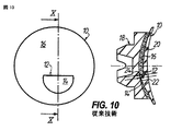
ブロッキングレンズがかなり均一でない横断面部分を有するとき、収縮の問題がよりいっそう明確になり、接着剤の均一でない部分が必要とされる。この一例が、図10に見られることができる。図10は、UV硬化接着剤20によってレンズブロック18にブロッキングされた、二焦点セグメント14とベースカーブ16との間のステップ不連続部12を有するフラットトップ二焦点レンズブランク10を示している。図10から明らかであるように、二焦点セグメント14とレンズブロック18とのギャップ22が二焦点セグメント14のすぐ上のギャップ24とかなり異なっているとき、収縮が問題とされ得る。この例では、UV硬化接着剤20の厚さの違いによって生じる収縮の違いが、二焦点セグメント14のすぐ上の決定的な/好ましくない歪みを生じ得る。
When the blocking lens has a non-uniform cross-sectional portion, the shrinkage problem becomes even more pronounced and a non-uniform portion of the adhesive is required. An example of this can be seen in FIG. FIG. 10 shows a flat top bifocal lens blank 10 having a
上の試みでは、上のUV光硬化性ブロッキング材料に関して残る収縮の問題を克服するために、考えられるレンズのベースカーブにほぼ合わせるように、複数(7か8)の異なるブロックのベースカーブを使用し、かくして、残る収縮の影響を最小にするように、接着剤の厚さを十分に均一に保つことが提案されている。図11は、複数のレンズブロック18を使用した従来技術を示している。これらレンズブロックの各々は、所定のブロックカーブを有するレンズ装着面26を有し、異なるレンズブロック18のブロックカーブは互いに異なる。図示される例において、レンズブロック18は、それぞれ、a)0.5ジオプトリ、b)2ジオプトリ、c)6ジオプトリ、d)10ジオプトリのブロックカーブ、即ち、ブロッキングされたレンズ10のブロッキング面28のそれぞれの曲率にほぼ合ったレンズカーブを有するほぼ球形のレンズ装着面26を有する。図11には、図面を簡略化するために4つの異なるレンズブロック18のみが示されているが、実際には、このシステムは、上述されたように、7か8の異なるレンズブロックを使用することができることが注意される。図11から明らかとなるように、各場合において、レンズブランク10とレンズブロック18との間のUV硬化接着剤20は、UV硬化接着剤20の収縮による歪みが起こらないように、比較的薄く、ほぼ均一な厚さを有する。
In the above attempt, multiple (7 or 8) different block base curves were used to roughly match the possible lens base curves to overcome the shrinkage problems remaining with the above UV light curable blocking materials. Thus, it has been proposed to keep the adhesive thickness sufficiently uniform so as to minimize the effects of residual shrinkage. FIG. 11 shows a conventional technique using a plurality of
しかし、複数の異なるブロックのベースカーブを使用するアプローチは、図10に示される状況では、役に立たない。複数のブロックのベースカーブに関するさらなる問題は、これら複数のカーブの管理である。適切なレンズブロックが、初めに、レンズカーブに合わせて選択される必要があり、そして、デブロッキングの後、(レンズブロックが再利用されると仮定すると)、これらは、カーブに従って適切に分類されて、別々の保持/分配容器内に収容される必要がある。かくして、複数のブロックカーブを使用することは、製造処理の複雑さを加え、誤りの確率を増加させ、さらに、結果として、レンズ製造のコストを増加させる。 However, the approach using multiple different block base curves is not useful in the situation shown in FIG. A further problem with the base curves of multiple blocks is the management of these multiple curves. Appropriate lens blocks must first be selected for the lens curve, and after deblocking (assuming the lens block is reused), they are properly classified according to the curve. And must be contained in separate holding / dispensing containers. Thus, using multiple block curves adds to the complexity of the manufacturing process, increases the probability of error, and consequently increases the cost of lens manufacturing.
本発明の目的は、全範囲の標準レンズをカバーするために必要とされるブロックカーブの数が最小にされ、かつ、結合剤としての放射線硬化材料の収縮に関する問題にも対処する、レンズブランクをブロッキングするための方法を提供することである。本発明の目的は、さらに、放射線で硬化されることができ、上の目的を満たすレンズブロッキングのための接着剤配合物を与えることである。 It is an object of the present invention to provide a lens blank that minimizes the number of block curves required to cover the full range of standard lenses and also addresses the problems associated with shrinkage of radiation curable material as a binder. It is to provide a method for blocking. It is a further object of the present invention to provide an adhesive formulation for lens blocking that can be cured with radiation and meets the above objectives.
上の目的は、請求項1、3、7、8でそれぞれ規定される特徴部分により解決される。本発明の効果的かつ適切な発展形態は、請求項2、4ないし6、9ないし16の規定内容を構成している。
The above object is solved by the features defined in
本発明の一態様によれば、所定の曲率のブロッキング面を有するレンズブランクをブロッキングするための方法が提供される。本方法は、
(a) 各々が所定のブロックカーブを有するレンズ装着面を有し、全てが同じブロックカーブを有する複数のレンズブロックを与える工程と、
(b) 前記複数のレンズブロックのうちの1つのレンズブロックを取り出す工程と、
(c) UV又は可視光で硬化する、重合していない(un-polymerized)状態の液体接着剤と、非重合固体(non polymerizing solid)としてのフィラーとを含む接着剤配合物を混合する工程と、
(d) 前記レンズブランクの前記ブロッキング面と、前記レンズブロックの前記レンズ装着面との少なくとも一方に、前記接着剤配合物を塗布する工程と、
(e) 前記レンズブランクの前記ブロッキング面が前記レンズブロックの前記レンズ装着面に面している状態で、前記レンズブロックに向かって前記レンズブランクを当接させる(urging)工程と、
(f) 所定の波長と強度とを有し、前記接着剤配合物の硬化を引き起こすのに十分な時間間隔で与えられるUV又は可視光を発生させて、この光を前記接着剤配合物に透過させる工程と、を具備し、
(g) 前記接着剤と前記フィラーとの混合比は、前記接着剤配合物が前記レンズブランクに過度の応力を与えることなく、かつ、前記接着剤配合物からの前記レンズブランクの剥離(de-bonding)がないよう硬化可能であるように、十分低い硬化に基づいた前記接着剤配合物の重合による寸法変化と発熱とを有するように選択される方法である。
According to one aspect of the present invention, a method is provided for blocking a lens blank having a blocking surface of a predetermined curvature. This method
(A) providing a plurality of lens blocks each having a lens mounting surface having a predetermined block curve, all having the same block curve;
(B) extracting one lens block of the plurality of lens blocks;
(C) mixing an adhesive formulation comprising a liquid adhesive in an un-polymerized state that is cured with UV or visible light and a filler as a non-polymerizing solid; ,
(D) applying the adhesive composition to at least one of the blocking surface of the lens blank and the lens mounting surface of the lens block;
(E) a step of urging the lens blank toward the lens block in a state where the blocking surface of the lens blank faces the lens mounting surface of the lens block;
(F) generating UV or visible light having a predetermined wavelength and intensity, provided at a time interval sufficient to cause curing of the adhesive formulation, and transmitting this light to the adhesive formulation; And comprising
(G) The mixing ratio of the adhesive and the filler is determined so that the adhesive composition does not apply excessive stress to the lens blank, and the lens blank is peeled from the adhesive composition (de- It is a method selected to have a dimensional change and heat generation due to polymerization of the adhesive formulation based on a sufficiently low cure so that it can be cured without bonding.
本発明のさらなる態様によれば、所定の曲率のブロッキング面を有するレンズブランクをブロッキングするための方法が提供される。本方法は、
(a) 各々が所定のブロックカーブを有するレンズ装着面を有し、いくつかのみが異なるブロックカーブを有する複数のレンズブロックを与える工程と、
(b) 前記ブロックカーブが前記ブロッキング面の前記曲率にできるだけ良く適合するように、前記レンズブランクの前記ブロッキング面の前記曲率に依存した特定のブロックカーブを有するレンズブロックを選択する工程と、
(c) UV又は可視光で硬化する、重合していない状態の液体接着剤と、非重合固体としてのフィラーとを含む接着剤配合物を混合する工程と、
(d) 前記レンズブランクの前記ブロッキング面と前記レンズブロックの前記レンズ装着面との少なくとも一方に、前記接着剤配合物を塗布する工程と、
(e) 前記レンズブランクの前記ブロッキング面が前記レンズブロックの前記レンズ装着面に面している状態で、前記レンズブロックに向かって前記レンズブランクを当接させる工程と、
(f) 所定の波長と強度とを有し、前記接着剤配合物の硬化を引き起こすのに十分な時間間隔で与えられるUV又は可視光を発生させて、この光を前記接着剤配合物に透過させる工程と、を具備し、
(g) 前記接着剤と前記フィラーとの混合比は、前記接着剤配合物が前記レンズブランクに過度の応力を与えることなく、かつ、前記接着剤配合物からの前記レンズブランクの剥離がないよう硬化可能であるように、十分低い硬化に基づいた前記接着剤配合物の重合の寸法変化と発熱とを有するように選択される方法である。
According to a further aspect of the invention, a method is provided for blocking a lens blank having a blocking surface of a predetermined curvature. This method
(A) providing a plurality of lens blocks each having a lens mounting surface with a predetermined block curve, only some with different block curves;
(B) selecting a lens block having a specific block curve depending on the curvature of the blocking surface of the lens blank so that the block curve fits as well as possible with the curvature of the blocking surface;
(C) mixing a non-polymerized liquid adhesive that is cured with UV or visible light and an adhesive formulation comprising a filler as a non-polymerized solid;
(D) applying the adhesive composition to at least one of the blocking surface of the lens blank and the lens mounting surface of the lens block;
(E) a step of bringing the lens blank into contact with the lens block in a state where the blocking surface of the lens blank faces the lens mounting surface of the lens block;
(F) generating UV or visible light having a predetermined wavelength and intensity, provided at a time interval sufficient to cause curing of the adhesive formulation, and transmitting this light to the adhesive formulation; And comprising
(G) The mixing ratio of the adhesive and the filler is such that the adhesive composition does not apply excessive stress to the lens blank and the lens blank does not peel from the adhesive composition. A method selected to have a dimensional change and exotherm of polymerization of the adhesive formulation based on a sufficiently low cure to be curable.
まず、上の従来技術と比較すると、両方法は、ブロックカーブの数の減少という共通点を有する。上の第1の方法では、使用される1つのブロックカーブのみが理想的な状況を示し、また、第2の方法に従ういくつかの、例えば2又は3の異なるブロックカーブを使用することも、製造処理の複雑さ、誤りの確率及びレンズ製造のコストを減少させることに関して、7又は8のブロックカーブを使用するよりもかなり優れていると感じられる。 First, compared with the above prior art, both methods have the common point of reducing the number of block curves. In the first method above, only one block curve used represents an ideal situation, and it is also possible to use several, eg 2 or 3 different block curves according to the second method. It appears to be much better than using 7 or 8 block curves in terms of reducing processing complexity, error probability and lens manufacturing costs.
さらに、再び上の従来技術と比較すると、本発明に係る方法は、UV又は可視光で硬化する、重合していない状態の液体接着剤と、非重合固体としてのフィラーとを含む接着剤配合物のレンズブロッキングでの使用、特に、接着剤とフィラーとの混合比が、接着剤配合物がレンズブランクに過度の応力を与えることなく、かつ、接着剤配合物からのレンズブランクの剥離がないよう硬化可能であるように、十分低い硬化に基づいた接着剤配合物の重合の寸法変化と発熱とを有するように選択されるという共通点を有する。 Furthermore, again compared to the prior art above, the method according to the present invention comprises an adhesive formulation comprising a non-polymerized liquid adhesive that is cured with UV or visible light and a filler as a non-polymerized solid. The lens blocking is used, especially when the mixing ratio of adhesive and filler is such that the adhesive formulation does not put excessive stress on the lens blank and the lens blank does not peel off from the adhesive formulation. In order to be curable, it has in common that it is selected to have a dimensional change and exotherm of the polymerization of the adhesive formulation based on a sufficiently low cure.
これに関連して、フィラーの使用は、いくつかの利点を与える。収縮のかなり部分が、重合中、材料の構造変化に由来するので、1つは、非重合固体としてのフィラーを液体の(重合していない)化合物に物理的に取り込んで、この結果、取り入れられたフィラー材料の少なくとも体積パーセンテージだけ、収縮を低減させることができる。 In this connection, the use of fillers offers several advantages. Since a significant portion of the shrinkage comes from the structural changes in the material during polymerization, one physically incorporates the filler as a non-polymerized solid into the liquid (non-polymerized) compound and is thus incorporated. Shrinkage can be reduced by at least a volume percentage of the filler material.
さらに、代表的なUV又は光放射硬化材料は、比較的低い温度で硬化すると考えられているが、硬化処理中、所定のレベルの発熱を示す。いくつかの場合において、特に、UV/VIS材料の体積が高いとき、この発熱反応が初期の液体温度を超えて材料の温度を20ないし40℃上げ得る。これらのより高い処理温度は、代わって、レンズブランクと、レンズブロックと、接着剤との間の異なるCTEs(熱拡散係数)により、レンズブランクに対する熱応力をもたらす。それ故、重合に由来する収縮を低減させることに加えて、代わって、フィラーの取り入れによるUV/VIS硬化性材料の体積の減少は、硬化反応の発熱する構成成分を減少させ、この結果、最終的な低い処理温度及び低い熱膨張をもたらす。 In addition, typical UV or light radiation curable materials are believed to cure at relatively low temperatures, but exhibit a predetermined level of heat generation during the curing process. In some cases, particularly when the volume of the UV / VIS material is high, this exothermic reaction can increase the temperature of the material by 20-40 ° C. above the initial liquid temperature. These higher processing temperatures instead result in thermal stresses on the lens blank due to different CTEs (thermal diffusion coefficients) between the lens blank, the lens block, and the adhesive. Therefore, in addition to reducing the shrinkage resulting from polymerization, instead, reducing the volume of the UV / VIS curable material by incorporating a filler reduces the exothermic components of the curing reaction, resulting in a final Low processing temperature and low thermal expansion.
収縮の源の両方(重合中の構造変化と重合による発熱)を減少させる組合せの効果は、同時に、必然的であるように、1又はいくつかのブロックカーブのみが最大限の範囲の標準レンズをブロッキングするために使用されているとき、一定でないUV/VIS材料の厚さを使用してレンズをうまくブロッキングする能力のために非常に有益であることが理解される。 The combined effect of reducing both the source of shrinkage (structural changes during polymerization and the exotherm due to polymerization), at the same time, requires only one or several block curves to have a standard lens with maximum range. When used to block, it is understood that it is very beneficial for the ability to successfully block the lens using a non-uniform UV / VIS material thickness.
フィラーを使用することのさらなる重要な利益は、UV/VIS硬化性材料の量を減少させることによるコストの削減である。UV/VIS硬化性材料は、比較的高価な化学成分、特に、非常に高価な傾向にある電磁放射(UV/VIS)硬化を開始するために使用されるフォトイニシエータを使用し、このような結果として、ブロッキング化合物のコストが比較的高くなる。これに加えて、いったん硬化すると、化合物は液体(重合されていない)状態に戻ることができない。これは、金属又はブロッキングワックス(又はe−カプロラクトンのような他の熱可塑性物質)を与えるのと同様にして再び溶かすことによって再利用することができないことを意味している。 A further important benefit of using fillers is a reduction in cost by reducing the amount of UV / VIS curable material. UV / VIS curable materials use relatively expensive chemical components, especially photoinitiators used to initiate electromagnetic radiation (UV / VIS) curing, which tends to be very expensive, and as a result As a result, the cost of the blocking compound is relatively high. In addition, once cured, the compound cannot return to the liquid (non-polymerized) state. This means that it cannot be reused by re-dissolving in the same way as providing a metal or blocking wax (or other thermoplastic such as e-caprolactone).
上の第1の方法では、即ち、レンズブロックが全て全く同じブロックカーブを有する場合には、全てのレンズブロックは、好ましくは、所定の母集団(population)のためにブロックされるように、レンズブランクのブロッキング面の曲率の分布に従って選択された同じブロックカーブを含むほぼ球形のレンズ装着面を有する。これは、異なる母集団が、異なる分布を示すことができ、それ故、使用する材料を最小にするために異なるブロックカーブを必要とすることを考慮している。例えば、あるアジアの母集団は、西欧や北米の母集団と比較すると、より低い(より平たい)ベースカーブであることが知られている。これは、使用する材料と最終的な光学性能との少なくとも一方をより最適にする(最小にする)ために、わずかに低いブロックカーブの選択をもたらす。 In the first method above, i.e. if all the lens blocks have exactly the same block curve, all the lens blocks are preferably blocked so that they are blocked for a given population. It has a substantially spherical lens mounting surface that includes the same block curve selected according to the curvature distribution of the blank blocking surface. This takes into account that different populations can exhibit different distributions and therefore require different block curves to minimize the materials used. For example, an Asian population is known to have a lower (flatter) base curve compared to Western and North American populations. This results in the selection of a slightly lower block curve in order to more optimize (minimize) at least one of the material used and the final optical performance.
上の第2の方法では、即ち、レンズブロックが異なるブロックカーブを有する場合には、全てのレンズブロックは、好ましくは、ほぼ球形のレンズ装着面を有し、2つの異なるブロックカーブのみのレンズブロック、即ち0ないし4ジオプトリの範囲内の凹ブロックカーブを有するレンズブロックと、4ないし8ジオプトリの範囲内の凹ブロックカーブを有するレンズブロックとが与えられる。しかし、ブロッキングされるレンズブランクのブロッキング面の形状に依存して、ブロックカーブは、凸であってもよい。 In the second method above, i.e. if the lens blocks have different block curves, all lens blocks preferably have a substantially spherical lens mounting surface and only two different block curve lens blocks. That is, a lens block having a concave block curve in the range of 0 to 4 diopters and a lens block having a concave block curve in the range of 4 to 8 diopters are provided. However, the block curve may be convex depending on the shape of the blocking surface of the lens blank to be blocked.
第2の方法の1つの好ましい実施の形態では、レンズブロックを選択する工程は、レンズブランクのブロッキング状態で効果的に行われ、レンズブロックのレンズ装着面と、レンズブランクのブロッキング面との間のギャップは、レンズブロックの中央領域で最小にされる。結果として、接着剤配合物の絶対収縮は、MRP(主要な参照点)の特に近くで非常にわずかな応力がたとえあってもレンズブランクに誘導されるように、中心領域で最小にされる。 In one preferred embodiment of the second method, the step of selecting the lens block is effectively performed in the blocking state of the lens blank, between the lens mounting surface of the lens block and the blocking surface of the lens blank. The gap is minimized in the central area of the lens block. As a result, the absolute shrinkage of the adhesive formulation is minimized in the central region, so that very little stress is induced, even near very close to the MRP (main reference point).
原則として、全ての種類の光に対して不透明な、即ち非透過性であるレンズブロックが使用されることができ、UV又は可視光は、接着剤配合物の硬化を引き起こすために、レンズブランクを通って接着剤配合物に透過される。しかし、透過UV又は可視光を許容することができるレンズブロックの使用が好ましい。UV又は可視光を発生させて、この光を接着剤配合物に透過させる工程は、光をレンズブロックを通って接着剤配合物に透過させることを含む。 In principle, lens blocks that are opaque to all types of light, i.e. non-transparent, can be used, and UV or visible light can cause lens blanks to cause curing of the adhesive formulation. Permeated through the adhesive formulation. However, the use of a lens block that can tolerate transmitted UV or visible light is preferred. Generating UV or visible light and transmitting this light through the adhesive formulation includes transmitting light through the lens block into the adhesive formulation.
また、本発明によると、レンズブロッキングで使用するための接着剤配合物が提供される。接着剤配合物は、(a)重合していない状態で液体であり、UV又は可視光で硬化する接着剤と、(b)非重合固体としてのフィラーとを含む。接着剤とフィラーとの混合比は、接着剤対フィラーの重量比が、70%/30%ないし30%/70%の範囲にある。試験が示すように、この範囲内の混合比は、接着剤配合物がレンズブランクに過度の応力を与えることなく、かつ、接着剤配合物からのレンズブランクの剥離がないよう硬化可能であるに、十分低い硬化に基づいた接着剤配合物の重合による寸法変化と発熱とをもたらすのに効果的である。また、フィラーを含む接着剤配合物は、レンズブロッキングに使用されたとき、上で既に説明されたように、従来の放射硬化ブロッキング材料の使用と比較して、コスト削減につながる。さらに、このような接着剤配合物は、最終的には、全範囲の標準レンズ(上の説明参照)をカバーするようにレンズ形成が必要とされるブロックカーブの数の減少のための「媒体(vehicle)」を表す。 The present invention also provides an adhesive formulation for use in lens blocking. The adhesive formulation includes (a) an adhesive that is liquid in an unpolymerized state and is cured with UV or visible light, and (b) a filler as a non-polymerized solid. The mixing ratio of adhesive to filler is such that the weight ratio of adhesive to filler is in the range of 70% / 30% to 30% / 70%. Tests indicate that the mixing ratio within this range is such that the adhesive formulation can be cured without undue stress on the lens blank and without the lens blank peeling from the adhesive formulation. It is effective to cause dimensional changes and heat generation due to polymerization of adhesive formulations based on sufficiently low cure. Also, adhesive formulations containing fillers, when used for lens blocking, lead to cost savings as compared to the use of conventional radiation curable blocking materials, as already explained above. In addition, such adhesive formulations ultimately result in a “medium” for reducing the number of block curves that require lens formation to cover the full range of standard lenses (see above). (Vehicle) ".
好ましくは、フィラーは、ブロッキングされたレンズ全体の又は部分的な屈曲及び移動を防ぐために、硬化された接着剤配合物の十分な堅さを与える固体粒子からなる。 Preferably, the filler consists of solid particles that provide sufficient stiffness of the cured adhesive formulation to prevent full or partial bending and movement of the blocked lens.
また、好ましいフィラー粒子の形状は、ほぼ球形であるが、円筒又は不規則な形状でもうまくいくことができる。球面形状の利点は、接着剤配合物の液体状態における粘性の改良(低い粘性)である。 Also, the preferred filler particle shape is approximately spherical, but cylindrical or irregular shapes can work well. The advantage of the spherical shape is the improved viscosity (low viscosity) in the liquid state of the adhesive formulation.
フィラー粒子のサイズは、一般的には、ブロッキングされるレンズブランクと指定されたレンズブロックとの間の最小ギャップよりも小さい必要がある。ここでは、2mmの最小ギャップが好ましく、これは、最も大きい粒子が2mmよりも小さく、好ましくは1mm以下であることを意味している。 The size of the filler particles generally needs to be smaller than the minimum gap between the blocked lens blank and the designated lens block. Here, a minimum gap of 2 mm is preferred, which means that the largest particles are smaller than 2 mm, preferably 1 mm or less.
デブロッキングを容易にするために、フィラーは、少量の金属繊維、粒状物又は粉状物、好ましくは、全体の組成重量が1ないし2%のアルミニウム繊維を含むことが好ましい。このような量の繊維は、マイクロ波エネルギで硬化されるブロッキング材料の加熱をかなり加速するように、マイクロ波エネルギの十分な吸収を与え、かくして、デブロッキングに先立ってブロッキング材料が軟化(“softened”)されることができる。 In order to facilitate deblocking, the filler preferably contains a small amount of metal fibers, granules or powders, preferably aluminum fibers having a total composition weight of 1 to 2%. Such an amount of fiber provides sufficient absorption of microwave energy to significantly accelerate the heating of the blocking material that is cured with microwave energy, thus softening the blocking material prior to deblocking ("softened"). ") Can be.
好ましくは、フィラー材料は、接着剤配合物の硬化を加速するために、UVと可視光との少なくとも一方の光活性波長に対して透過性か半透過性かの少なくとも一方である。 Preferably, the filler material is at least one of transmissive and semi-transmissive to at least one photoactive wavelength of UV and visible light to accelerate the curing of the adhesive formulation.
フィラー材料は、さらに、低水分吸収特性を有することができる。これは、完全にブロッキングされたレンズが薄膜コーティング処理に通常使用される真空チャンバ内に取り込まれたとき、重要である。 The filler material can further have low moisture absorption characteristics. This is important when a fully blocked lens is incorporated into a vacuum chamber typically used for thin film coating processes.
本発明の概念を続けると、フィラー材料は、25℃ないし80℃のガラス転移温度(Tg)を有することができる。このようなフィラー材料を使用することによって、例えば十分な堅さや硬さであるような所定の機械特性が、(代表的には室温の近くの)表面仕上処理温度で果されることができる。そして、デブロッキングを容易にするために、Tgを超えた温度に上げることによって変えられることができる。これに関連して、80℃の上限は、デブロッキングを容易にするために、表面仕上されたレンズを永久的に損傷する温度を超えた硬化ブロッキング材料の温度より上まで上げる必要は全くないことを保証している。 Continuing with the inventive concept, the filler material can have a glass transition temperature (Tg) of 25 ° C to 80 ° C. By using such filler materials, certain mechanical properties can be achieved at surface finish processing temperatures (typically near room temperature), eg, sufficient stiffness or hardness. And to facilitate deblocking, it can be changed by raising the temperature above Tg. In this context, the 80 ° C upper limit need not be raised above the temperature of the cured blocking material beyond the temperature that permanently damages the surface-finished lens to facilitate deblocking. Guarantee.
最後に、フィラー材料は、リグラインド(reground)状態であるUV又は可視光硬化接着剤と、e−カプロラクトン、エチルメチルアクリレートアクリル酸(Ethyl-Methyl-Acrylate-Acrylic Acid)から誘導されたターポリマ、ポリカーボネート、ポリエチレン(PET)、高メタクリレート樹脂(High Methacrylate Resin)、メタクリル酸エチル樹脂(Ethyl Methacrylate Resin)、メタクリル酸共重合体樹脂(Methacrylate Copolymer Resin)、ブチルメタクリレート樹脂(Butyl Methacrylate Resin)及びメチル/n−ブチルメタクリル酸共重合体樹脂(Methyl/n-Butyl Methacrylate Copolymer Resin)を含むプラスチック材料とを含むグループから選択されるのが好ましい。特にそのようなフィラー材料のそれぞれの利点は、本発明の好ましい実施の形態の以下の記述から明らかになる。 Finally, the filler material is a terpolymer, polycarbonate derived from a reground, UV or visible light curable adhesive and e-caprolactone, Ethyl-Methyl-Acrylate-Acrylic Acid. , Polyethylene (PET), high methacrylate resin (Ethyl Methacrylate Resin), methacrylic acid copolymer resin (Methacrylate Copolymer Resin), butyl methacrylate resin (Butyl Methacrylate Resin) and methyl / n- It is preferably selected from the group comprising plastic materials including butyl methacrylic acid copolymer resin (Methyl / n-Butyl Methacrylate Copolymer Resin). In particular, the advantages of each such filler material will become apparent from the following description of preferred embodiments of the invention.
以下では、本発明が、添付の、特に概略的な図面を参照して、実施形態の好ましい例に基づいて、詳細に説明される。 In the following, the invention will be described in detail on the basis of preferred examples of embodiments with reference to the attached, in particular schematic, drawings.
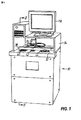
眼用レンズをブロッキングするための装置が、一般的に、添付の図において参照符号30で示されている。このブロッキング装置30は、上部32と、上部32を部分的に閉じるためのフード構造体34とを有するキャビネットを含む。レンズ運搬部36は、上部32に取り付けられた第1のリニアアクチュエータ38に移動可能に装着されている。第1のリニアアクチュエータ38は、これに沿ってレンズ運搬部36を移動させるための、かつ、これの位置を監視するための第1のサーボモータ又はステッパモータユニットを有する。第1のリニアアクチュエータ38とアライメントされ、前記キャビネットの上部32に組み込まれたブロッキング装置30は、イメージングステーション40と、走査ステーション42と、レンズブロッキングステーション44とを有する。ブロッキング装置30は、イメージングステーション40に焦点を合わせたカメラ46と、接着剤配合物のリザーバ48と、前記レンズブロッキングステーション44に接着剤配合物をポンピングするためのポンピングユニット50とを囲んでいる(図2参照)。ブロッキング装置30は、さらに、これの動作を制御するための中央処理装置52の形態である制御部を含む。
An apparatus for blocking an ophthalmic lens is generally indicated by
イメージングステーション40は、カメラ46から受信された画像情報に基づいて、中央処理装置52で生成されたレンズの向きの情報を表示するためのスクリーン56の補助により、レンズブランク54が適切にアライメントされ、レンズブロッキング処理の開始状態に置くことを確実にするように、レンズの向きのために利用される。イメージングステーション40のさらなる構造及び機能の詳細に関しては、US2005/0139309Aが参照される。
The
いったんレンズブランク54の向き及び位置パラメータが決定されると、レンズブランク54は、レンズブランク54のブロッキング面58を走査するために、イメージングステーション40から走査ステーション42まで、レンズ運搬部36により移動される。ここでも、レンズ運搬部36及び走査ステーション42の構造及び機能に関する詳細は、US2005/0139309Aが参照される。
Once the orientation and position parameters of the
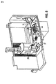
いったんレンズブランク54のブロッキング面58が走査されると、レンズブランク54は、走査ステーション42からレンズブロッキングステーション44まで、レンズ運搬部36によって移動される。レンズブロッキングステーション44は、上向きに面したレンズブロック62のレンズ装着面64を備えたレンズブロック62を受け、かつ支持するためのUV及び可視光透過レンズブロック支持部60を含む。この例では、レンズブロック62は、少なくともUVスペクトルを、好ましくは可視スペクトルも透過することができる透過性材料であるべきである。レンズブロック62のさらなる構造及び機能の特徴部分に関して、特に、レンズブロック62のクランピング部分を介して、レンズブロック62がレンズブロッキングステーション44に保持されることができ、後者は、表面仕上機であり、US2005/0250430Aが参照される。
Once the blocking
UV光源66(図6参照)は、レンズブロック支持部60中のアパチャ68を通る光を向けて、さらに、UV透過性レンズブロック62を通るUV光を向けるように、装着されている点で、レンズブロック支持部60と関連している。中央処理装置52の一部を形成することができる光源アクチュエータは、UV光源66の始動と停止とを制御するためにUV光源66に接続されている。このUV光源66は、UVスペクトル内と可視スペクトル中とにある高い強度の短い継続時間の光のパルスを放出するフラッシュランプを組み込むことができる。
The UV light source 66 (see FIG. 6) is mounted so as to direct light passing through the
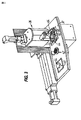
UV/可視光で硬化する接着剤配合物を分配するためのディスペンサが、参照符号70で示されている。ディスペンサ70は、ディスペンサアーム74の一端にディスペンサノズル72を有する。参照符号76により図示されるようなモータ又はリニア又は他のモータであることができるアームアクチュエータは、レンズブロック62のレンズ装着面全体に亘ってレンズブランク54の配置を邪魔しないように、レンズ装着面64に隣接した展開位置(図5)から、レンズ装着面64とレンズ運搬部36との明確な後退位置(図4)へと(又は逆に)、ディスペンサアーム74を移動させるように設けられることができる。
A dispenser for dispensing an adhesive formulation that cures with UV / visible light is indicated at 70. The
ディスペンサアーム74は、単にディスペンサノズル72の位置を制御する。従って、ディスペンサアーム74は、図示されるように、回転可能であるというよりむしろ入れ子式(telescopic)であることができ、シリンダ内の流体圧力駆動ピストンのようなリニアアクチュエータにより制御されることができる。
The
ディスペンサノズル72は、ディスペンサノズル72に接着剤配合物を供給するポンピングユニット50を介して接着剤配合物リザーバ48と流体連通している。あるいは、接着剤配合物リザーバ48は、加圧されることができ、かくして、ポンプの必要性をなくす。
The
ここに図示される本実施形態では、好ましくは交換可能なプレ充填ユニットとしての接着剤配合物リザーバ48は、重合していない、即ち液体のUV/VIS硬化性接着剤と、非重合固体としての適切なフィラーとからなるレディーミックス(ready-mixed)接着剤配合物を含んでいる。しかし、これに代わるものとして、ブロッキング装置は、ブロッキング装置30に交換可能に取り付けられた適切な容器内に収容されることができる上の構成成分から接着剤配合物を準備するための混合ユニットを備えていてもよい。
In the present embodiment illustrated here, the
ディスペンサノズル72は、このディスペンサノズル72が展開位置にあるとき、ディスペンサノズル72を通る接着剤配合物の分配を制御するために中央処理装置52と通信するバルブか他のシャットオフメカニズムを備えている。また、異なる制御構成体が使用されてもよい。制御の簡単な形態は、ディスペンサノズル72が開いて保持されている時間を監視することである。定量ポンプのような他の制御も使用されることができる。一般的に、いかなる制御が選択されても、レンズブランク54のブロッキング面58とレンズブロック62のレンズ装着面64との間のギャップをほぼ充填する測定された量の接着剤配合物を分配することができる。
The
使用中、測定された量のUV/VIS硬化性接着剤配合物は、レンズブロック62のレンズ装着面64上に、ディスペンサ70のディスペンサノズル72によって分配される。レンズブランク54は、レンズ装着面64に面しているレンズブランク54のブロッキング面58を備えたレンズブロック62の上に、レンズ運搬部36によって動かされる。そして、レンズ運搬部36は、レンズブランク54のブロッキング面58がレンズブロック62のレンズ装着面64から所定の距離になるまで、レンズ装着面64に向かって、液体接着剤配合物78へとレンズブランクを動かす(図6参照)。
During use, a measured amount of UV / VIS curable adhesive formulation is dispensed by the
ブロッキング面58とレンズ装着面64との間の配置及び空間的な関係が知られているので、オペレータが介入することなく、必要とされる接着剤配合物78の量が自動的に計算され、分配されることができる。
Since the arrangement and spatial relationship between the blocking
この段階では、UV光は、UV光源66により発生されて、所定の波長及び強度で、接着剤配合物78が硬化するのに十分な継続時間、レンズブロック62を透過し、かくして、レンズブランク54をレンズブロック62に結合する。
At this stage, UV light is generated by the UV light source 66 and is transmitted through the
最終工程として、レンズブロックに取着されたレンズブランク54を備えたレンズブロック62が、レンズブロッキングステーション44から取り外されて、レンズ運搬部36から解放される。
As a final step, the
図7は、以下の工程を含むブロッキング処理により得られるブロッキング結果を示している。 FIG. 7 shows a blocking result obtained by a blocking process including the following steps.
(a) 各々が所定のブロックカーブを有するレンズ装着面64を有する複数のレンズブロック62を与える工程。これらレンズブロック62の全てが、同じブロックカーブを有する。例に示されるように、全てのレンズブロック62が、5ジオプトリのブロックカーブを有するほぼ球形のレンズ装着面64を有する。
(A) A step of providing a plurality of lens blocks 62 each having a
(b) 複数のレンズブロック62のうちの1つのレンズブロック62を取り出す工程。処方作業場では、これらレンズブロック62は、通常、個々のレンズブロック62が取り出されることができる保持/分配容器内に収容されている。この例では、レンズブロック62が同じであるので、選択は必要ない。
(B) A step of taking out one
(c) 重合していない状態の液体のUV/VIS硬化性接着剤と、非重合固体としてのフィラーとを含む接着剤配合物を混合する工程。ここでは、接着剤とフィラーとの混合比は、接着剤配合物78がレンズブランク54に過度の応力を与えることなく、かつ、接着剤配合物78からのレンズブランク54の剥離がないよう硬化可能であるように、十分低い硬化に基づいた接着剤配合物78の重合による寸法変化と発熱とを有するように選択される。前に示されるように、このような混合は、ブロッキング目的のために接着剤配合物78を分配する直前に、好ましくは、ブロッキング装置30内で、又はこれに代わる手段としてより前に、ことによると処方作業場の外で前もって、行われることができる。
(C) mixing an adhesive formulation comprising an unpolymerized liquid UV / VIS curable adhesive and a filler as a non-polymerized solid; Here, the mixing ratio of adhesive and filler can be cured so that the
(d) 好ましくはレンズブロック62のレンズ装着面64に液体接着剤配合物78を塗布する工程。
(D) A step of applying the
(e) レンズブロック62に向かってレンズブランク54を当接させる工程、又は逆、これら両方の工程。レンズブランク54のブロッキング面58がレンズブロック62のレンズ装着面64に面している状態で、レンズブランク54とレンズブロック62の間の相対的な動きは、当然重要である。
(E) A step of bringing the
(f) 所定の波長と強度とを有し、接着剤配合物78の硬化を引き起こすのに十分な時間間隔で与えられるUV又は可視光を発生させて、この光を接着剤配合物78に透過させる工程。
(F) generating UV or visible light having a predetermined wavelength and intensity, provided at a time interval sufficient to cause curing of the
従来技術を示す図11と比較すると、図7は、(a)0.5ジオプトリ、b)2ジオプトリ、c)6ジオプトリ、d)10ジオプトリ)のブロッキング面の曲率に関して、図11に示されるのと同じレンズブランク54を示している。しかし、この例では、5ジオプトリの1つのブロックカーブのみがブロッキングされている。これは、ブロックカーブの数の減少に関連する問題及び提案される解決策が効果的であると感じられる理由を示すのに役立つ。
Compared to FIG. 11 showing the prior art, FIG. 7 is shown in FIG. 11 for the curvature of the blocking surface of (a) 0.5 diopters, b) 2 diopters, c) 6 diopters, d) 10 diopters). The
図7では、一見、あたかも、ブロッキング材料の使用は、図11で使用されているのが見られるよりもかなり大きいように思える。しかし、単一のブロックカーブが、レンズのベースカーブの統計的な分布において、メガネレンズの大部分に最もよく適しているとして選ばれ得る理由であると仮定すれば、使用されるブロッキング材料の量は、初めに考えるほど大きくない。 In FIG. 7, it appears that the use of blocking material appears to be significantly larger than that used in FIG. However, assuming that a single block curve can be chosen as the best fit for the majority of eyeglass lenses in the statistical distribution of the base curve of the lens, the amount of blocking material used Is not as big as initially thought.
これに関連して、図9は、特定の母集団のための代表的なベース(正面)カーブの分布を示している。この分布、及び最適なブロックカーブの適切な選択を考慮することにより、ブロッキング材料の使用は、7のブロックカーブと比較して、1のブロックカーブを使用したとき、10ないし15%だけ増加される。2のブロックカーブが使用されると、ブロッキング材料の使用の増加は、7のブロックカーブよりも6%のみであると計算される。ブロッキング材料の消費量に関するこの重要でない増加は、1又は2のブロックカーブ対通常直面する高いカーブ数のみを管理することに関連するコスト削減によって、容易に埋め合わせられる。 In this regard, FIG. 9 shows a typical base (frontal) curve distribution for a particular population. By considering this distribution and the appropriate choice of optimal block curve, the use of blocking material is increased by 10 to 15% when using one block curve compared to 7 block curves. . If a block curve of 2 is used, the increase in use of blocking material is calculated to be only 6% over the block curve of 7. This insignificant increase in blocking material consumption is easily offset by the cost savings associated with managing only one or two block curves versus the high number of curves normally encountered.
使用するブロックカーブの数が少ないときに生じる問題の1つは、図7a)、b)並びにd)から明らかとなる。これは、一定でないブロッキング材料の厚さに関連する均一でない収縮の問題である。収縮は、UV/VIS硬化性接着剤の重合によって主に引き起こされるが、この材料が硬化されたとき、熱の影響からも生じ得る。 One of the problems that arise when the number of block curves used is small becomes apparent from FIGS. 7a), b) and d). This is a non-uniform shrinkage problem associated with non-constant blocking material thickness. Shrinkage is mainly caused by the polymerization of the UV / VIS curable adhesive, but can also result from thermal effects when the material is cured.
使用される化学物質のタイプ及び硬化中に達する温度に依存して、2ないし10%かそれ以上の範囲に及ぶ材料の収縮を見ることが可能である。高温は、硬化放射のエネルギから生じ得るが、重合中、化学反応により引き起こされる発熱を引き起こし得る。初期の室温を超えて、10ないし40℃に及ぶ温度が、容易に達せられることができる。そして、ブロックアセンブリが室温まで冷えると、これは、最終的なアセンブリの異なるCTEs(熱拡散係数)と機械特性とに従って収縮する。この収縮は、内部的に抑制されて、最終的なアセンブリにおける好ましくない機械的(熱的)応力をもたらし得る。 Depending on the type of chemical used and the temperature reached during curing, it is possible to see material shrinkage ranging from 2 to 10% or more. High temperatures can result from the energy of the curing radiation, but can cause an exotherm caused by chemical reactions during polymerization. Beyond the initial room temperature, temperatures ranging from 10 to 40 ° C. can easily be reached. And as the block assembly cools to room temperature, it shrinks according to the different CTEs (thermal diffusion coefficients) and mechanical properties of the final assembly. This shrinkage can be internally constrained, resulting in undesirable mechanical (thermal) stress in the final assembly.
収縮は三次元効果であるが、所望の点での軸方向に対する収縮量は、一般的に、この点でのUV/VIS硬化性接着剤の厚さに比例していると考えられている。十分な収縮であるとすると、ブロッキング材料の配置の変化をもたらすのを明確に見ることができる。この変化は、好ましくない2つの影響を有する可能性がある。1つは、レンズブランクからブロッキング材料を「引き離す(pulling away)」ことにより引き起こされるブロッキング材料からのレンズブランクの剥離である。図7a)では、この剥離は、レンズブランク54の中心部でさらに起こる傾向にあるが、図7d)では、端部でより見られる。この場合において、最も良くない状況は、図7a)で見られる。この状況では、中心部でのいかなる剥離も、表面仕上中、レンズブランク54の支持不足により中心部で許容できない歪みを引き起こす場合がある。これに加えて、剥離が存在しない場合でさえも、最終的な薄い中心部のレンズの配置のため、中心部での収縮は、中心部での最終的な曲率を変更する傾向があり、この結果、倍率(power)の誤りを取り入れ得る。図7d)に見られる場合には、倍率の誤りはあまり重要ではない。なぜならば、レンズの中心部は、比較的厚い(正の倍率)まま留まり、それ故、高い堅さと、収縮により生じる圧力により耐えることができるからである。
Although shrinkage is a three-dimensional effect, the amount of shrinkage in the axial direction at a desired point is generally considered to be proportional to the thickness of the UV / VIS curable adhesive at this point. Assuming sufficient shrinkage, it can be clearly seen that this results in a change in the placement of the blocking material. This change can have two undesirable effects. One is delamination of the lens blank from the blocking material caused by “pulling away” the blocking material from the lens blank. In FIG. 7a) this delamination tends to occur further in the center of the
特に上の問題に対処するために、非重合固体として特に選択されたフィラーが、以下でさらに詳細に説明されるように、UV/VIS硬化性ブロッキング材料に加えられる。 To address the above particular problems, fillers specifically selected as non-polymerized solids are added to the UV / VIS curable blocking material as will be described in more detail below.
図8を参照すると、これは、以下の工程を含むさらなるブロッキング処理により得られるブロッキング結果を示している。
(a) 各々が所定のブロックカーブを有するレンズ装着面64を有する複数のレンズブロック62を与える工程。これらレンズブロック62は、いくつかの異なるブロックカーブを有する。この例では、全てのレンズブロック62は、ほぼ球形のレンズ装着面64を有する。また、2つの異なるブロックカーブのみのレンズブロック62、即ち、凹形のブロックカーブの0.5ジオプトリのレンズブロック62(図8のa)並びにb))と、5ジオプトリの凹形のブロックカーブを含むレンズブロック62(図8のc)並びにd))が設けられている。
Referring to FIG. 8, this shows a blocking result obtained by a further blocking process including the following steps.
(A) A step of providing a plurality of lens blocks 62 each having a
(b) ブロックカーブがブロッキング面の曲率にできるだけ良く適合するように、レンズブランク54のブロッキング面58の曲率に依存した特定のブロックカーブを有するレンズブロック62を選択する工程。示される例では、この工程は、レンズブロック62のレンズ装着面64とレンズブランク54のブロッキング面58とのギャップが、ブロックされたレンズブランク54への応力の取り入れを最小にする又は抑圧するために、レンズブロック62の中央部で最小にされるという効果を果す。このようにして、0.5のベースのレンズブロック62は、0.5及び2のベースのレンズブランク54に割り当てられ(図8a)並びにb))、5のベースのレンズブロック62は、6及び10のベースのレンズブランク54(図8のc)並びにd))に割り当てられる。
(B) A step of selecting the
この処理における残りの工程は、図7に関連して上で説明した(c)ないし(f)の工程と同じである。 The remaining steps in this process are the same as steps (c) to (f) described above with reference to FIG.
重合していない状態で液体であるUV又は可視光硬化性接着剤と、非重合固体としてのフィラーとを含む接着剤配合物78で満たされるべきである材料の必要性に関して、以下のことが注意される。
Regarding the need for materials that should be filled with an
一般的に、硬化材料の所定の機械的及び熱的特性を達成することが好ましい。これらの特性は、良いレンズ支持部により達成され、要求に応じたレンズのデブロッキング能力を維持する、又は高める。この文脈において、「デブロッキング」は、化学的、熱的、機械的又は他の手段もしくはこれらの実用的な組合せによって、レンズと接着剤配合物との間の接着結合(adhesive bond)を解放することを意味している。 In general, it is preferred to achieve the predetermined mechanical and thermal properties of the curable material. These properties are achieved with a good lens support and maintain or enhance the deblocking ability of the lens on demand. In this context, “deblocking” releases the adhesive bond between the lens and the adhesive formulation by chemical, thermal, mechanical or other means or a practical combination thereof. It means that.
多機能フィラー又は特定のフィラーの組合せが、同時に、収縮、反応による発熱及びコストを削減しながら、材料特性を維持又は変更するために使用されることができる。フィラーの他の潜在的な機能は、デブロッキングをより容易にするために、所定の制御条件の下で接着特性を変更することである。 Multifunctional fillers or combinations of specific fillers can be used to maintain or change material properties while simultaneously reducing shrinkage, reaction heat generation and cost. Another potential function of the filler is to change the adhesive properties under certain control conditions to make deblocking easier.
硬化材料は、通常、機械加工処理中、屈曲、レンズ又は切断工具のすぐ近くのレンズの領域の移動を防ぐために十分な堅さが必要である。しかし、可撓性のブロッキング材料を有することは、デブロッキング処理中、この材料をレンズから「剥がす(peel)」ことをより簡単にする。硬質でもろい材料は、剥がすのが難しく、より小さい片に壊れる傾向にあるが、軟質で柔軟で粘着性のある材料は、1つの片でより容易に剥がれる。 The curable material usually needs to be stiff enough to prevent bending, movement of the lens area in the immediate vicinity of the lens or cutting tool during the machining process. However, it has a flexible blocking material during deblocking processing, the material lens or al "peel (peel)" It is easier to. Hard and brittle materials are difficult to peel off and tend to break into smaller pieces, while soft, soft and tacky materials are more easily peeled off in one piece.
機械的な剥離が他のデブロッキング方法に関して選ばれていれば、好ましい材料は、デブロッキング中に十分に低いながらも、表面仕上を可能にするのに十分に高いレベルの硬さであるか、又はデブロッキングの前に「軟化」処理を受けるかであることができる。この「軟化」処理は、例えば、温水に浸すこと、又は他の形態かIRやマイクロ波のような放射波長との少なくとも一方に晒すことによって、ブロッキング材料を加熱することができる。この場合、接着剤配合物は、硬度の減少のような所定の修正可能な特性に関してデブロッキングをよりよく支持するように設計されることができ、また、接着性の減少と組み合わせられる。 If mechanical debonding is chosen for other deblocking methods, the preferred material is sufficiently low in hardness during deblocking, but at a sufficiently high level of hardness to allow surface finish, Or it can be subjected to a “softening” treatment prior to deblocking. This “softening” treatment can heat the blocking material, for example, by immersing it in warm water, or exposing it to other forms or radiation wavelengths such as IR or microwave. In this case, the adhesive formulation can be designed to better support deblocking with respect to certain modifiable properties, such as a decrease in hardness, and is combined with a decrease in adhesion.
少量の金属繊維、粒状物又は粉状物が、マイクロ波エネルギで硬化されるブロッキング材料の加熱性を高めるためにフィラーに加えられることができる。液体接着剤に混合された少量(組成物の全重量の1か2%)の微細なアルミニウム繊維は、UV放射がまだ容易に接着剤に入り込むことができるので、効果を防ぐのに十分でないが、材料の加熱をかなり加速するために十分なマイクロ波エネルギの吸収を提供する。15秒のマイクロ波照射時間は、アルミニウム繊維なしでの20秒と比較すると、30℃から25℃だけ材料の温度上げるために必要である全てである。 Small amounts of metal fibers, granules or powders can be added to the filler to increase the heatability of the blocking material that is cured with microwave energy. A small amount (1 or 2% of the total weight of the composition) of fine aluminum fibers mixed in a liquid adhesive is not enough to prevent the effect, as UV radiation can still easily penetrate the adhesive. Provide sufficient microwave energy absorption to significantly accelerate the heating of the material. A microwave exposure time of 15 seconds is all that is needed to raise the temperature of the material by 30 to 25 ° C. compared to 20 seconds without aluminum fibers.
硬化されるブロッキング材料を「軟化する」ことによってデブロッキング材料を容易にする硬化ブロッキング材料の加熱を加速するための他の可能性は、一般的に高い電気抵抗を有する金属粒子のわずかなパーセンテージ(フィラーの全質量の1ないし5%)を加えることと、粒子に電流を誘導するための誘導加熱要素を使用することとである。代わって、電流への電気抵抗は、粒子に熱を発生させて、周辺の材料に伝導し、かくして、ブロッキング化合物を加熱する。また、他の非金属、炭素のような誘導材料及び所定の半導体粒子が、誘導加熱技術に関して使用されることができる。 Another possibility for accelerating the heating of the cured blocking material that facilitates the deblocking material by “softening” the cured blocking material is generally a small percentage of metal particles with high electrical resistance ( Adding 1 to 5% of the total mass of the filler) and using an induction heating element to induce a current in the particles. Instead, the electrical resistance to the current generates heat in the particles and conducts them to the surrounding material, thus heating the blocking compound. Also other non-metallic, inductive materials such as carbon and certain semiconductor particles can be used for induction heating techniques.
標準の表面仕上処理温度で硬度及び堅さを維持又は改良し、なおもデブロッキング中の可撓性を高めるために使用されることができる多機能フィラー材料の一例は、e−カプロラクトン(e-Caprolactone)である。e−カプロラクトン(及びポリカプロラクトン)は、熱可塑性のモノマであり、UVと可視光線との少なくとも一方の透過を許容するのに十分なように半透明であり、それ故、液体のUV接着剤のマトリックスと、非重合固体フィラーとしてのe−カプロラクトン粒子との硬化を可能にする。e−カプロラクトンの重量の65%程度の充填比が、うまく硬化され、レンズブランクとレンズブロックとの硬さ及び接着に関して試験された。室温では、この材料は、かなり硬いように選択されることができる(例えば、50ないし70ショアD)。そして、表面仕上の後、硬化されたブロッキング材料は、加熱されて、e−カプロラクトン粒子が軟質である(例えば、10ないし40ショアD)が液体でない点に達することができる。これらの温度は、レンズを破損しないように十分低い(例えば、35℃ないし60℃)。マトリックス中のUV/VIS硬化接着成分は、固体のまま留まるが、これらの温度でかなり柔らかいe−カプロラクトン粒子は、全体のマトリックスをより軟質にし、かくして、レンズからのブロッキング材料の除去の容易さをかなり改良する。e−カプロラクトンは、比較的低いガラス転移温度(Tg)を有し、全ての処理が、この場合においてTgより高いところで行われる。また、e−カプロラクトンと同様の他の材料も特定されることができる。 An example of a multi-functional filler material that can be used to maintain or improve hardness and stiffness at standard surface finish temperatures and still increase flexibility during deblocking is e-caprolactone (e- Caprolactone). e-caprolactone (and polycaprolactone) is a thermoplastic monomer that is translucent enough to allow transmission of at least one of UV and visible light, and therefore is a liquid UV adhesive. Allows curing of the matrix and e-caprolactone particles as non-polymerized solid filler. Filling ratios as high as 65% of the weight of e-caprolactone were successfully cured and tested for hardness and adhesion between the lens blank and the lens block. At room temperature, this material can be selected to be fairly stiff (eg, 50-70 Shore D). And after the surface finish, the cured blocking material can be heated to reach a point where the e-caprolactone particles are soft (eg, 10 to 40 Shore D) but not liquid. These temperatures are sufficiently low (eg, 35 ° C. to 60 ° C.) so as not to damage the lens. While the UV / VIS cured adhesive component in the matrix remains solid, the e-caprolactone particles that are fairly soft at these temperatures make the entire matrix softer, thus facilitating the removal of the blocking material from the lens. It improves considerably. e-Caprolactone has a relatively low glass transition temperature (Tg) and all processing takes place in this case above Tg. Other materials similar to e-caprolactone can also be specified.
他の変形例は、表面仕上処理温度(代表的には、室温に近い)を超えるTgで、表面仕上されたレンズに永久的に損傷する温度(80℃)よりも低い、フィラー材料を使用することである。マットウェブのデータベース(www.matweb.com)は、25℃と80℃との間のTgを有する235のポリマ材料を挙げている。これらは、処理温度(例えば、高い堅さと硬度)で所定の機械特性を達成するために使用されることができ、そして、Tgを超えて温度を上げることによってこれらの機械特性を変える。このような材料の1つは、エクソンモービル「EscorAT320EMA−AA三元重合体」である。これは、エチルメチルアクリル酸アクリルである。これは、室温で固体であり、固体粒子の形態で液体のUV/VIS硬化性接着剤材料に混合されることができる。これは、これ自体がアクリル酸ベースであるので、アクリル酸ベースのUV/VIS硬化性接着剤に結合するための優れた表面を提供する。 Another variation uses a filler material that has a Tg above the surface finish processing temperature (typically near room temperature) and lower than the temperature that permanently damages the surface finish lens (80 ° C.). That is. The Mattweb database (www.matweb.com) lists 235 polymer materials with Tg between 25 and 80 ° C. They can be used to achieve predetermined mechanical properties at processing temperatures (eg, high stiffness and hardness) and alter these mechanical properties by raising the temperature beyond Tg. One such material is ExxonMobil “EscorAT320EMA-AA terpolymer”. This is ethyl methyl acrylate acrylic. It is solid at room temperature and can be mixed into a liquid UV / VIS curable adhesive material in the form of solid particles. This provides an excellent surface for bonding to acrylic acid-based UV / VIS curable adhesives because they are themselves acrylic acid based.
このアプリケーションのためのフィラーとして複数の好ましい機能性を有することが示されている他の材料の系統類(family)は、「エルバサイト(登録商標)」という商号で、ルサイトインターナショナルスペシャリティポリマ社により購入されることができる。これらの材料は、例えば、高メタクリレート樹脂、メタクリル酸エチル樹脂、メタクリル酸共重合体樹脂、又はブチルメタクリルレート樹脂であることができる。これらの特性は、低い分子量から非常に高い分子量に及ぶこと、及び1ないし20(ヌープ硬度数)のチューコン(Tukon)硬度、及び15℃と110℃の間でTgが変化することである。このアプリケーションのために実効性が証明されているこれら材料の1つは、36℃のTgを有する「エルバサイト(登録商標)2550」(メチル/nブチルメタクリル酸塩共重合体)である。これは、ヌープ硬度数4で比較的柔らかいが、比較的高い充填パーセンテージ(60%ないし70%)が使用されたとき、表面仕上のために十分な硬さを確実にし、なおも、比較的低い硬さ及び特に熱的特性によるデブロッキングを容易にすることが可能である。これらの製品に加えられた利益は、小さな直径の球体のビーズの形態で直接購入されることができるということである。10ないし200マイクロメートルの代表的なビーズ直径があり、これは、より大きなペレットを許容できるサイズまでグラインドするためにプレ処理なしですぐに使用可能にする。 Another material family that has been shown to have multiple preferred functionalities as fillers for this application is the trade name “Elvasite®” by Lucite International Specialty Polymers. Can be purchased. These materials can be, for example, high methacrylate resins, ethyl methacrylate resins, methacrylic acid copolymer resins, or butyl methacrylate resins. These properties range from low molecular weight to very high molecular weight, and a Tukon hardness of 1 to 20 (Knoop hardness number), and Tg varying between 15 ° C and 110 ° C. One of these materials that has proven effective for this application is “Elbasite® 2550” (methyl / n-butyl methacrylate copolymer) with a Tg of 36 ° C. This is relatively soft with a Knoop hardness number of 4, but ensures a sufficient hardness for surface finish when a relatively high filling percentage (60% to 70%) is used, yet relatively low It is possible to facilitate deblocking due to hardness and especially thermal properties. An added benefit to these products is that they can be purchased directly in the form of small diameter spherical beads. There is a typical bead diameter of 10 to 200 micrometers, which makes it ready for use without pre-treatment to grind larger pellets to an acceptable size.
また、フィラーも、カッター工具を研磨せず、破壊しない。切断又は研削工具で硬化されたブロッキング材料を深く切るなら、それは工具を破損するべきではない。いくつかの高められた磨耗性は、所定の状況で許容されることができるが、消費者によって耐えられる高められた磨耗性の量は、通常は、全体の処理の経済性によって動かされる。 Also, the filler does not polish or destroy the cutter tool. If the blocking material cured with a cutting or grinding tool is cut deep, it should not damage the tool. While some increased wear can be tolerated in a given situation, the amount of increased wear that can be tolerated by the consumer is usually driven by the overall processing economics.
好ましいフィラー粒子の形状(一般的に球形である)とサイズ(2mmより小さい、特に好ましくは1mm以下)が、既に議論されている。フィラーの他の重要な特性は、UVと可視光との少なくとも一方の電磁エネルギが、UV/VIS硬化性接着材料中に埋め込まれたフォトイニシエータに達するのをブロックする、又は何らかの方法で禁止することによって、硬化処理を妨げてはならない、又は過度に減速させてはならないということである。 従って、光活性波長に対する透過性と半透過性との少なくとも一方が、互換性のあるフィラーの選択にとって非常に重要であると考えられる。 Preferred filler particle shapes (generally spherical) and sizes (less than 2 mm, particularly preferably less than 1 mm) have already been discussed. Another important property of the filler is that it blocks or somehow prohibits the electromagnetic energy of at least one of UV and visible light from reaching the photoinitiator embedded in the UV / VIS curable adhesive material. This means that the curing process must not be disturbed or excessively slowed down. Therefore, it is considered that at least one of transparency and translucency for the photoactive wavelength is very important for selection of compatible fillers.
フィラー材料のさらなる好ましい特徴部分又は機能は、非常に低いガス放出材料を組み込むことによってガス抜け(outgassing)を減少させ、かくして、完全なブロックされたレンズが薄膜コーティングの処理で通常使用される真空チャンバに取り入れられるならば、「真空ポンピング時間」をかなり減少させることである。ガス抜けの3つの主な供給源は、溶剤からのVOC(揮発性有機化合物)放出と、液体樹脂の硬化されていない残りと、ブロッキング材料内にトラップされた水分であることができる。これらの3つの全ての材料が、コーティング処理に必要とされる真空のレベルに達することが望まれているよりも難しい又は遅いところで、真空中で蒸発して、この状態を形成することができる。 A further preferred feature or function of the filler material is to reduce outgassing by incorporating a very low outgassing material, thus a vacuum chamber where fully blocked lenses are normally used in thin film coating processing. If so, the "vacuum pumping time" is significantly reduced. The three main sources of outgassing can be VOC (volatile organic compound) emissions from the solvent, the uncured remainder of the liquid resin, and moisture trapped in the blocking material. All three of these materials can evaporate in vacuum to form this state where it is more difficult or slower than it is desired to reach the level of vacuum required for the coating process.
溶剤の場合には、好ましいアプローチは、液体化合物中に溶剤が取り入れられるのを防ぐことである。これは、一般的に、硬化されるブロッキング材料中の吸収に溶剤が全く残っていないことを保証するために、100%固体タイプの樹脂を使用することが好ましいことを意味している。不完全な硬化は、「硬化された」材料内に残っている液体樹脂の原因となり得る。この問題は、一般的に、UV/VISの透過性/反透過性フィラーを再び与えることと、レンズブロックを走査するためのより焦点が合わせられた高パワー光源のような硬化技術又は超高エネルギキセノンフラッシュランプ技術を与えることとによって対処される。第3の状況は、含水量がある。この場合、フィラーのための低吸湿材料を選択することが重要になる。このような材料の例は、2つの名前を挙げると、ポリカーボネート及びPETである。 In the case of a solvent, the preferred approach is to prevent the solvent from being incorporated into the liquid compound. This generally means that it is preferable to use a 100% solids type resin to ensure that no solvent remains for absorption in the cured blocking material. Incomplete curing can cause liquid resin to remain in the “cured” material. This problem is generally associated with re-providing UV / VIS transmissive / anti-transmissive fillers and curing techniques such as more focused high power light sources for scanning lens blocks or ultra-high energy. Addressed by giving xenon flash lamp technology. The third situation is water content. In this case, it is important to select a low hygroscopic material for the filler. Examples of such materials are polycarbonate and PET, to name two.
最後に、強く好まれたアプローチは、リグラインド状態のUV/VIS硬化接着材料をフィラーとして直接再利用することである。提案されることは、レンズがデブロッキングされるとき、硬化されたUVブロッキング材料を捨てる代わりに、オペレータが適切な粒子のサイズに材料をグラインドするように設計された小さなグラインダ(grinder)にこれを簡単に入れることができるということである。そして、このリグラインド材料は、既知の測定技術、装置及び方法を使用することで適切な混合比における新しい硬化処理されていないUV/VIS硬化性接着剤に混ぜられる。混合ノズルを使用したメータリングスクリュは、1つのアプローチである。好ましい混合比は、フィラー粒子対液体UV/VIS硬化接着材料が、40%/60%と70%/30%との間にある。この概念は、比較的正確な混合比における、2つの構成成分の連続したかオンデマンドの混合を可能にし、また、正しい量の混合接着剤配合物をレンズブロックに届けるために使用されることができる。他のより簡単なアプローチは、バッチのための正しい量の構成成分の重さを計って、ハンドドリルのような補助ペイントミキサの動力付きのハンドミキサで混合することである。 Finally, the strongly preferred approach is to directly recycle the regrinded UV / VIS cured adhesive material as a filler. What is suggested is that instead of throwing away the cured UV blocking material when the lens is deblocked, this can be done by a small grinder designed for the operator to grind the material to the appropriate particle size. It is easy to put in. This regrind material is then mixed with a new uncured UV / VIS curable adhesive in an appropriate mix ratio using known measurement techniques, equipment and methods. A metering screw using a mixing nozzle is one approach. A preferred mixing ratio is between 40% / 60% and 70% / 30% filler particles to liquid UV / VIS cured adhesive material. This concept allows continuous or on-demand mixing of the two components at a relatively accurate mixing ratio and can be used to deliver the correct amount of mixed adhesive formulation to the lens block. it can. Another simpler approach is to weigh the correct amount of components for the batch and mix with a powered hand mixer of an auxiliary paint mixer such as a hand drill.
リグラインド材料を使用する主な効果の1つは、通常、他のフィラーに関して予想されて得られる収縮及び発熱の減少と、同時に、コストをさらにも削減するということである。硬化されたブロッキング材料は、通常、最終的に廃棄され、従って、50%から70%の再成立は、経済的利益と環境的利益との両方を有する。コストがほぼゼロであるので、コスト便益が実現される。唯一のコストは、ハンドリング、グラインディング及びミキシングである。環境に関する利益は、処分体積がかなり減少するという事実により生じる。他の効果は、新しい硬化されていない材料が、2つの間の化学的類似性による硬化材料にかなり十分に接着されるということである。さらなる他の効果は、混合比のいかなる変化も、温度依存硬度/可撓性、軟化点等のような最終的な機械的及び熱的特性に影響を与えないことである。これは、混合誤りに対する許容性がかなり大きいので、混合された接着剤配合物の混合及び品質管理を簡素化する。他の効果は、一貫して予測できるUV透過性であり、「オールインワン(all in one)」化合物のデザインは、異なる又は完全に互換性のないフィラー、フィラーの品質の変化等により影響しない。 One of the main effects of using regrind materials is that it usually reduces the shrinkage and exotherm expected for other fillers, while at the same time further reducing costs. The cured blocking material is usually eventually discarded, so a 50% to 70% re-establishment has both economic and environmental benefits. Cost benefits are realized because the cost is nearly zero. The only cost is handling, grinding and mixing. Environmental benefits arise from the fact that the disposal volume is significantly reduced. Another effect is that the new uncured material adheres fairly well to the cured material due to the chemical similarity between the two. Yet another effect is that any change in the mixing ratio does not affect the final mechanical and thermal properties such as temperature dependent hardness / flexibility, softening point, etc. This simplifies mixing and quality control of the mixed adhesive formulation as it is much more tolerant of mixing errors. Another effect is consistently predictable UV transparency, and the design of “all in one” compounds is not affected by different or completely incompatible fillers, filler quality changes, etc.
ここでは、最後の2つのパラグラフが、まず「純粋な」硬化されておらずかつ満たされていないUV/VIS硬化性接着材料を使用して始められ、そして、この材料が硬化された後に、新しい液体(硬化されていない)を含むフィラーとして使用されると仮定することが注意される。この点から進んで、レンズがデブロッキングされるとき、UVs/VIS硬化ブロッキング材料は、グラインディングにより再利用されて、非固体フィラーとして新しい硬化されていないUV/VIS硬化性材料に混合される。 Here, the last two paragraphs are first started using a “pure” uncured and unfilled UV / VIS curable adhesive material, and after this material is cured, a new It is noted that it is assumed to be used as a filler containing a liquid (uncured). Proceeding from this point, when the lens is deblocked, the UVs / VIS cured blocking material is reused by grinding and mixed with the new uncured UV / VIS curable material as a non-solid filler.
例1
3mmの粒子のサイズを有するソルベイの「ポリカプラクトンC6500」の重量比60%と、カナダのニューブランズウィックのモンクトンのMotionFab(609891 NB Ltd.)により販売され、アクリル樹脂、モノマ及びフォトイニシエータを含む「ジェネラル#3」UV硬化ブロッキング化合物(PL110284−02、製造月日1月23日06−01)の重量比40%との混合物が、試験された。(ジェネラル#3ブロッキング化合物は、カナダのニューブランズウィックのモンクトンのマイクロオプティクスデザインコーポレーションにより販売されている「ウルトラグリップ(登録商標)」として以前は知られていた。)以下の例でのように、接着剤配合物の個々の構成成分、即ち液体のUV硬化性接着剤と固体のフィラー粒子とが、手動で徹底的に混合された。
Example 1
60% by weight of Solvay's “Polycapracton C6500” with a particle size of 3 mm and sold by MotionFab (609891 NB Ltd.) of Moncton, New Brunswick, Canada, including acrylics, monomers and photoinitiators. A mixture of a general # 3 "UV cured blocking compound (PL110284-02, date of manufacture January 23, 06-01) with a weight ratio of 40% was tested. (The General # 3 blocking compound was formerly known as “UltraGrip®” sold by Moncton's Microoptics Design Corporation of New Brunswick, Canada.) Adhesion as in the following example: The individual components of the agent formulation, namely the liquid UV curable adhesive and the solid filler particles, were thoroughly mixed manually.
混合された生成物は、「ホワイト」C6500粒子が「D」タイプのバルブと共に装着された「ヒュージョン」UVランプ(アメリカのマリーランド20878−1357のクロッパーロードガイザーバルグ910のヒュージョンUVシステム社から入手されることができる)を使用して、数十秒の照射時間の後、完全な硬化を得るために十分な光活性波長を透過されたという事実により、うまく硬化された。 The blended product is obtained from the “Fusion” UV lamp (“Maryland” 20878-1357, Cropper Road Geyserberg 910, Fusion UV Systems, Inc.) equipped with “White” C6500 particles with a “D” type bulb. Was cured well due to the fact that after several tens of seconds of irradiation time, enough photoactive wavelength was transmitted to obtain complete cure.
この材料の主な欠点は、粒子のサイズが大きいこと及びC6500のコストが比較的高いことであるように思える。混合されて硬化されたサンプルの室温における硬度は、39ないし55ショアDの範囲にあると測定されており、これは、硬化されたジェネラル#3(38ショアD)の硬度にほぼ匹敵し、またC6500は、57ショアDで測定された。複数の表示の平均値は、45.6ショアDであった。各構成成分の硬度の大きな変化及び密接な相関関係の理由は、C6500粒子の上に直接ゲージ点を有する大きな粒子のサイズと測定の確率とに寄与する。また、C6500粒子は、ジェネラル#3の均一でない厚さで覆われており、さらに、測定値の予測不可能性に加えられた。 The main disadvantage of this material seems to be the large size of the particles and the relatively high cost of C6500. The room temperature hardness of the mixed and cured sample has been measured to be in the range of 39 to 55 Shore D, which is roughly comparable to the hardness of cured General # 3 (38 Shore D), and C6500 was measured at 57 Shore D. The average of the multiple displays was 45.6 Shore D. The reason for the large change in hardness and close correlation of each component contributes to the size of the large particles with gauge points directly on the C6500 particles and the probability of measurement. C6500 particles were also covered with a non-uniform thickness of General # 3, which was further added to the unpredictability of the measurements.
しかし、50℃のデブロッキング温度での35ショアDに対する平均硬度の減少として測定された硬化された接着剤配合物の軟化は、明確に見られ、デブロッキングを容易にした。 However, the softening of the cured adhesive formulation, measured as a decrease in average hardness for 35 Shore D at a deblocking temperature of 50 ° C., was clearly seen and facilitated deblocking.
C6500の大きな粒子のサイズは、2つの主な理由により問題であると考えられた。第1に、これは、レンズブランクとレンズブロックとの間で達成可能な最小のギャップを増加させるということであり、それ故、ブロッキングに必要とされる材料の量を増加させる。第2の問題は、非常に薄いレンズの光学パワーの小さい表面張力波(ripple)又は変化を引き起こす不規則な収縮が見られることである。これは、粒状物間の収縮が、粒状物のすぐ上の収縮よりも大きいことにより説明され、他の起こり得る起因ファクタは、硬化されたブロッキング材料によって与えられる支持部の堅さの変化を引き起こす硬度の変化である。 The large particle size of C6500 was considered a problem for two main reasons. First, this increases the minimum achievable gap between the lens blank and the lens block, thus increasing the amount of material required for blocking. The second problem is the appearance of irregular contractions that cause a small surface tension ripple or change in the optical power of very thin lenses. This is explained by the fact that the shrinkage between the granulates is greater than the shrinkage just above the granulates, and other possible causal factors cause changes in the stiffness of the support provided by the cured blocking material It is a change in hardness.
例2
ルサイトインターナショナルスペシャリティポリマ社から得られた「エルバサイト(登録商標)2550」(nメチル/ブチル基のメタクリル酸塩共重合体)とジェネラル#3との混合物が、60%の比率で、即ち重さのUVによる合成する重さのエルバサイト2550ないし40%で準備された。これは、硬化された接着剤配合物の全体の硬度を40.4ショアに増加させ、硬度のはるかに低い変化をもたらした。
Example 2
A mixture of “Elvasite® 2550” (n-methyl / butyl methacrylate copolymer) obtained from Lucite International Specialty Polymers with a general # 3 ratio of 60%, ie, heavy It was prepared with 2550-40% of the elbasite weighed by UV. This increased the overall hardness of the cured adhesive formulation to 40.4 shore, resulting in a much lower change in hardness.
不規則な直径の一般的に球形か隋円形の粒子は、エルバサイト2550の特定のサンプルで、350マイクロメートルの平均粒度で、15ないし460マイクロメートルに及んだ。 Irregular diameter generally spherical or oval particles ranged from 15 to 460 micrometers with an average particle size of 350 micrometers for a particular sample of Elbasite 2550.
低いTg(36℃)と、50℃のデブロッキング温度で硬化された混合物の28ショアDの比較的低い硬度とは、デブロッキング温度で処理(表面化)温度と高い柔軟性で堅さの良い組合せを与えた。また、350マイクロメートルの粒子のサイズが最小のギャップに加えて、0.5mmよりも小さな最小ギャップに加えて、一定の収縮と支持を提供するための効果であると考えられた。そして、最終的にエルバサイト2550フィラーのUV透過性/半透過性は、試験された全ての異なる光源による接着剤配合物を硬化することを非常に簡単にした。 The low Tg (36 ° C.) and the relatively low hardness of 28 Shore D of the mixture cured at a deblocking temperature of 50 ° C. is a combination of processing (surface) temperature and high flexibility and stiffness at the deblocking temperature. Gave. Also, the size of the 350 micron particles was considered to be an effect to provide a constant shrinkage and support in addition to a minimum gap smaller than 0.5 mm in addition to a minimum gap. And finally, the UV transmissive / semi-transmissive properties of the Elbasite 2550 filler made it very easy to cure the adhesive formulations from all the different light sources tested.
例3
第3の化合物は、エクソンモービルの「Escor AT320 EMA-AAターポリマ」を使用して準備された。Escor AT320の重量比60%と、再びジェネラル#3の重量比40%とが使用された。
Example 3
The third compound was prepared using ExxonMobil's “Escor AT320 EMA-AA terpolymer”. A 60% weight ratio of Escor AT320 and again a 40% weight ratio of General # 3 were used.
このフィラーの粒子の形状は、不規則であり、粒子のサイズは、1.5mmのスクリーンを通り抜けたほどであった。 The shape of the filler particles was irregular and the size of the particles was about to pass through a 1.5 mm screen.
この接着剤配合物は、熱的特性の概要から効果的な材料であることがわかり、23℃の表面処理温度及び55℃ないし60℃デブロッキング温度での支持のために試験された。硬度は1℃あたり0.4ショアDの傾きで減少するが、25℃で比較的低い25ショアD硬度で始められた。この硬度が38ショアDよりも低い硬度であるので、このフィラー材料の系統類からの他の製品が20℃ないし25℃の表面処理温度で、より良い堅さを提供することができると感じられる。 This adhesive formulation was found to be an effective material from a summary of thermal properties and was tested for support at 23 ° C. surface treatment temperature and 55 ° C. to 60 ° C. deblocking temperature. Hardness decreased with a slope of 0.4 Shore D per degree Celsius, but began with a relatively low 25 Shore D hardness at 25 degrees Celsius. Since this hardness is lower than 38 Shore D, it seems that other products from this family of filler materials can provide better stiffness at surface treatment temperatures of 20 ° C. to 25 ° C. .
例4
第4の化合物が、硬化されてできたフィラーを使用して、即ち、重量比50%の重合された純粋なジェネラル#3と、重量比50%の液体(硬化されていない)のジェネラル#3とにより準備され、試験された。この例では、フィラーが同じジェネラル#3であるので、最終的な硬化された接着剤配合物は、常にジェネラル#3である。
Example 4
The fourth compound uses a cured filler, i.e. 50% by weight polymerized pure general # 3 and 50% by weight liquid (uncured) general # 3 And prepared and tested. In this example, since the filler is the same general # 3, the final cured adhesive formulation is always general # 3.
硬化された材料は、0.5mmないし1.5mmの粒子のサイズ、1mmの平均のサイズを有するように研磨された。これら粒子は、使用されるグラインディング処理のため、形状が非常に不規則であった。より高い充填比は、ことによると不規則な粒子の形状により、得るのは難しい。 The cured material was ground to have a particle size of 0.5 mm to 1.5 mm and an average size of 1 mm. These particles were very irregular in shape due to the grinding process used. Higher packing ratios are difficult to obtain, possibly due to irregular particle shapes.
この材料が、試験される他の充填材料の全ての効果、即ち低収縮及び重合の低発熱を有する。重合状態において、即ち重合されていない固体フィラーとして、これは、UV透過性であり、充填されていない材料の同じ機械的及び熱的特性を有する非常にコヒーレントな固体のかたまりを形成している。ブロッキング材料自体を再利用するこのアプローチの主な効果は、コスト及び材料の消耗を減らすことである。 This material has all the effects of the other filler materials tested, ie low shrinkage and low exotherm of polymerization. In the polymerized state, ie as an unpolymerized solid filler, it forms a very coherent solid mass that is UV transparent and has the same mechanical and thermal properties of the unfilled material. The main effect of this approach of reusing the blocking material itself is to reduce cost and material consumption.
例5
第5のブロッキング材料は、ドイツ、ハンブルグのAlroko GmbH & Co. KGから購入される小さいアルミニウム繊維の全体にフィラーの重量比を2%加えた、上の例4に従う硬化されていない接着剤配合物(Aluminiumfasern Al Mg S Kurzfaser F35)から準備された。
Example 5
The fifth blocking material is an uncured adhesive formulation according to Example 4 above, in which a 2% filler weight ratio is added to the entire small aluminum fibers purchased from Alroko GmbH & Co. KG, Hamburg, Germany. (Aluminiumfasern Al Mg S Kurzfaser F35).
繊維の大きさ及び形状は、非常に不規則であった。これらは、0.5mmないし3mmの長さの範囲にあり、また、直径0.1mmないし0.5mmの範囲で変化する。 The size and shape of the fibers were very irregular. These range from 0.5 mm to 3 mm in length and vary from 0.1 mm to 0.5 mm in diameter.
繊維を加える目的は、マイクロ波エネルギを使用して加熱時間を単に短くすることである。この目的のために、これは非常に効果的であることが証明されている。 The purpose of adding the fiber is to simply shorten the heating time using microwave energy. For this purpose, this has proven to be very effective.
前のブロッキング材料の欠点をほぼ克服する新しいレンズブロッキング材料(接着剤配合物)が提案される。この新しい材料は、低収縮、重合の低発熱及びデブロックする能力を改良することを含む所望の材料特性を果す又は改良するために、通常のUVと可視光(VIS)との少なくとも一方の硬化性高分子材料を、非重合固体として特別に選択されたフィラーと結合し、同時にこのようなUV/VIS放射硬化性材料に関連している高いコストを削減する。この新しい材料は、最大限の範囲の標準レンズを覆うために必要とされる異なるブロックカーブの数が最小にされる所定のブロックカーブを有するレンズ装着面でレンズブロックにレンズブランクをブロックする方法で使用されている。
以下に、本出願の出願当初の特許請求の範囲に記載された発明を付記する。
[1]所定の曲率のブロッキング面(58)を有するレンズブランク(54)をブロッキングするための方法であって、
(a) 各々が所定のブロックカーブを有するレンズ装着面(64)を有し、全てが同じブロックカーブを有する複数のレンズブロック(62)を与える工程と、
(b) 前記複数のレンズブロック(62)のうちの1つのレンズブロック(62)を取り出す工程と、
(c) UV又は可視光で硬化する、重合していない状態の液体接着剤と、非重合固体としてのフィラーとを含む接着剤配合物(78)を混合する工程と、
(d) 前記レンズブランク(54)の前記ブロッキング面(58)と前記レンズブロック(62)の前記レンズ装着面(64)との少なくとも1つに、前記接着剤配合物(78)を塗布する工程と、
(e) 前記レンズブロック(62)の前記レンズ装着面(64)に面している前記レンズブランク(54)の前記ブロッキング面(58)と共に、前記レンズブロック(62)に向かって前記レンズブランク(54)を当接させる工程と、
(f) 所定の波長と強度とを有し、前記接着剤配合物(78)の硬化を引き起こすのに十分な時間間隔で与えられるUV又は可視光を発生させて、この光を前記接着剤配合物(78)に透過させる工程と、を具備し、
(g) 前記接着剤と前記フィラーとの混合比は、前記接着剤配合物(78)が前記レンズブランク(54)に過度の応力を与えることなく、かつ、前記接着剤配合物(78)からの前記レンズブランク(54)の剥離がないよう硬化可能であるように、十分に低い硬化に基づいた、前記接着剤配合物(78)の重合による寸法変化と発熱とを有するように選択される方法。
[2]全ての前記レンズブロック(62)は、所定の母集団のためにブロックされるように、レンズブランク(54)の前記ブロッキング面(58)の曲率の分布に従って選択された同じブロックカーブを含むほぼ球形のレンズ装着面(64)を有する[1]の方法。
[3]所定の曲率のブロッキング面(58)を有するレンズブランク(54)をブロッキングするための方法であって、
(a) 各々が所定のブロックカーブを有するレンズ装着面(64)を有し、いくつかのみが異なるブロックカーブを有する複数のレンズブロック(62)を与える工程と、
(b) 前記ブロックカーブが、前記ブロッキング面(58)の前記曲率にできるだけ良く適合するように、前記レンズブランク(54)の前記ブロッキング面(58)の前記曲率に依存した特定のブロックカーブを有するレンズブロック(62)を選択する工程と、
(c) UV又は可視光で硬化する、重合していない状態の液体接着剤と、非重合固体としてのフィラーとを含む接着剤配合物(78)を混合する工程と、
(d) 前記レンズブランク(54)の前記ブロッキング面(58)と前記レンズブロック(62)の前記レンズ装着面(64)との少なくとも1つに、前記接着剤配合物(78)を塗布する工程と、
(e) 前記レンズブロック(62)の前記レンズ装着面(64)に面している前記レンズブランク(54)の前記ブロッキング面(58)と共に、前記レンズブロック(62)に向かって前記レンズブランク(54)を当接させる工程と、
(f) 所定の波長と強度とを有し、前記接着剤配合物(78)の硬化をするのに十分な時間間隔で与えられるUV又は可視光を発生させて、この光を前記接着剤配合物(78)に透過させる工程と、を具備し、
(g) 前記接着剤と前記フィラーとの混合比は、前記接着剤配合物(78)が前記レンズブランクに過度の応力を与えることなく、かつ、前記接着剤配合物(78)からの前記レンズブランクの剥離がないよう硬化可能であるように、十分低い硬化に基づいた前記接着剤配合物の重合による寸法変化と発熱とを有するように選択される方法。
[4]全ての前記レンズブロック(62)は、ほぼ球形のレンズ装着面(64)を有し、
2つの異なるブロックカーブのみのレンズブロック(62)、即ち0ないし4ジオプトリの範囲内の凹ブロックカーブを有するレンズブロック(62)と、4ないし8ジオプトリの範囲内の凹ブロックカーブを有するレンズブロック(62)とが与えられる[3]の方法。
[5]前記レンズブロック(62)を選択する工程は、前記レンズブランク(54)のブロッキング状態で効果的に行われ、前記レンズブロック(62)の前記レンズ装着面(64)と、前記レンズブランク(54)の前記ブロッキング面(58)との間のギャップは、前記レンズブロック(62)の中心領域で最小にされる[3]又は[4]の方法。
[6]前記レンズブロック(62)は、透過UV又は可視光を許容することができ、前記UV又は可視光を発生させて、この光を前記接着剤配合物(78)に透過させる工程は、前記レンズブロック(62)を通して前記接着剤配合物(78)に光を透過させることを含む[1]ないし[5]のいずれか1の方法。
[7]重合していない状態で液体である、UV又は可視光で硬化する接着剤と、非重合固体としてのフィラーとを含む接着剤配合物(78)のレンズブロッキングでの使用。
[8]重合していない状態で液体である、UV又は可視光で硬化する接着剤と、非重合固体としてのフィラーとを含むレンズブロッキングのための接着剤配合物(78)であって、前記接着剤とフィラーとの混合比は、接着剤対フィラーの重量比で70%/30%ないし30%/70%の範囲にある接着剤配合物。
[9]前記フィラーは、固体粒子からなる、[1]ないし[8]のいずれか1に従う方法、使用並びに接着剤配合物(78)。
[10]前記フィラー粒子の形状は、ほぼ球形である[9]の方法、使用並びに接着剤配合物(78)。
[11]前記フィラー粒子のサイズは、2mm未満、好ましくは1mm以下である、[8]又は[9]の方法、使用並びに接着剤配合物(78)。
[12]前記フィラーは、金属繊維、粒状物又は粉状物、好ましくは、全体の組成重量の1ないし2%のアルミニウム繊維を含む、[1]ないし[11]のいずれか1の方法、使用並びに接着剤配合物(78)。
[13]前記フィラー材料は、UVと可視光との少なくとも一方の光活性波長に対して透過性か半透過性かの少なくとも一方である、[1]ないし[12]のいずれか1の方法、使用並びに接着剤配合物(78)。
[14]前記フィラー材料は、低水分吸収特性を有する、[1]ないし[13]のいずれか1の方法、使用並びに接着剤配合物(78)。
[15]前記フィラー材料は、25℃ないし80℃のガラス転移温度(Tg)を有する、[1]ないし[14]のいずれか1の方法、使用並びに接着剤配合物(78)。
[16]前記フィラー材料は、リグラインド状態であるUV又は可視光硬化接着剤と、e−カプロラクトン、エチルメチルアクリレートアクリル酸から誘導されたターポリマ、ポリカーボネート、ポリエチレン(PET)、高メタクリレート樹脂、メタクリル酸エチル樹脂、メタクリル酸共重合体樹脂、ブチルメタクリレート樹脂及びメチル/n−ブチルメタクリル酸共重合体樹脂を含むプラスチック材料とを含むグループから選択される、[1]ないし[15]のいずれか1の方法、使用並びに接着剤配合物(78)。
A new lens blocking material (adhesive formulation) is proposed that substantially overcomes the drawbacks of the previous blocking material. This new material cures at least one of normal UV and visible light (VIS) to achieve or improve desired material properties including low shrinkage, low exotherm of polymerization, and improved ability to deblock. The functional polymeric material is combined with a filler specifically selected as a non-polymeric solid, while at the same time reducing the high costs associated with such UV / VIS radiation curable materials. This new material is a method of blocking a lens blank on a lens block with a lens mounting surface that has a predetermined block curve that minimizes the number of different block curves required to cover the full range of standard lenses. It is used.
The invention described in the scope of claims at the beginning of the filing of the present application will be appended.
[1] A method for blocking a lens blank (54) having a blocking surface (58) having a predetermined curvature,
(A) providing a plurality of lens blocks (62) each having a lens mounting surface (64) having a predetermined block curve, all having the same block curve;
(B) taking out one lens block (62) of the plurality of lens blocks (62);
(C) mixing an unpolymerized liquid adhesive that cures with UV or visible light and an adhesive formulation (78) comprising a filler as a non-polymerized solid;
(D) Applying the adhesive composition (78) to at least one of the blocking surface (58) of the lens blank (54) and the lens mounting surface (64) of the lens block (62). When,
(E) The lens blank (62) toward the lens block (62) together with the blocking surface (58) of the lens blank (54) facing the lens mounting surface (64) of the lens block (62). 54) abutting;
(F) generating UV or visible light having a predetermined wavelength and intensity and provided at sufficient time intervals to cause curing of the adhesive formulation (78), and this light is applied to the adhesive formulation; Passing through the object (78),
(G) The mixing ratio of the adhesive and the filler is such that the adhesive composition (78) does not apply excessive stress to the lens blank (54) and the adhesive composition (78). Selected to have a dimensional change and exotherm due to polymerization of the adhesive formulation (78) based on a sufficiently low cure so that the lens blank (54) can be cured without delamination. Method.
[2] The same block curve selected according to the curvature distribution of the blocking surface (58) of the lens blank (54) so that all the lens blocks (62) are blocked for a given population. The method of [1], comprising a substantially spherical lens mounting surface (64).
[3] A method for blocking a lens blank (54) having a blocking surface (58) having a predetermined curvature,
(A) providing a plurality of lens blocks (62) each having a lens mounting surface (64) having a predetermined block curve, only some of which have different block curves;
(B) having a specific block curve depending on the curvature of the blocking surface (58) of the lens blank (54) so that the block curve fits the curvature of the blocking surface (58) as well as possible. Selecting a lens block (62);
(C) mixing an unpolymerized liquid adhesive that cures with UV or visible light and an adhesive formulation (78) comprising a filler as a non-polymerized solid;
(D) Applying the adhesive composition (78) to at least one of the blocking surface (58) of the lens blank (54) and the lens mounting surface (64) of the lens block (62). When,
(E) The lens blank (62) toward the lens block (62) together with the blocking surface (58) of the lens blank (54) facing the lens mounting surface (64) of the lens block (62). 54) abutting;
(F) generating UV or visible light having a predetermined wavelength and intensity, provided at a time interval sufficient to cure the adhesive formulation (78), and applying this light to the adhesive formulation Passing through the object (78),
(G) The mixing ratio of the adhesive and the filler is such that the adhesive composition (78) does not apply excessive stress to the lens blank and the lens from the adhesive composition (78). A method selected to have a dimensional change and exotherm due to polymerization of the adhesive formulation based on a sufficiently low cure so that it can be cured without peeling of the blank.
[4] All the lens blocks (62) have a substantially spherical lens mounting surface (64),
A lens block (62) with only two different block curves: a lens block (62) having a concave block curve in the range of 0 to 4 diopters, and a lens block having a concave block curve in the range of 4 to 8 diopters ( 62). The method of [3].
[5] The step of selecting the lens block (62) is effectively performed in a blocking state of the lens blank (54), and the lens mounting surface (64) of the lens block (62) and the lens blank. The method of [3] or [4], wherein a gap between the blocking surface (58) of (54) is minimized in a central region of the lens block (62).
[6] The lens block (62) can tolerate transmitted UV or visible light, and generates the UV or visible light and transmits the light to the adhesive formulation (78). The method of any one of [1] to [5], comprising transmitting light through the lens block (62) to the adhesive formulation (78).
[7] Use in lens blocking of an adhesive formulation (78) comprising an adhesive that is liquid in an unpolymerized state and is cured with UV or visible light, and a filler as a non-polymerized solid.
[8] An adhesive formulation (78) for lens blocking comprising an adhesive which is liquid in an unpolymerized state and is cured with UV or visible light, and a filler as a non-polymerized solid, An adhesive formulation wherein the mixing ratio of adhesive to filler is in the range of 70% / 30% to 30% / 70% by weight of the adhesive to filler.
[9] The method, use and adhesive composition (78) according to any one of [1] to [8], wherein the filler comprises solid particles.
[10] The method, use and adhesive composition (78) of [9], wherein the filler particles are substantially spherical in shape.
[11] The method, use and adhesive formulation (78) of [8] or [9], wherein the size of the filler particles is less than 2 mm, preferably 1 mm or less.
[12] The method according to any one of [1] to [11], wherein the filler comprises metal fibers, granules or powders, preferably aluminum fibers of 1 to 2% of the total composition weight As well as an adhesive formulation (78).
[13] The method according to any one of [1] to [12], wherein the filler material is at least one of transparent and semi-transmissive to at least one photoactive wavelength of UV and visible light. Use and adhesive formulation (78).
[14] The method, use, and adhesive composition (78) of any one of [1] to [13], wherein the filler material has low moisture absorption characteristics.
[15] The method, use and adhesive formulation (78) of any one of [1] to [14], wherein the filler material has a glass transition temperature (Tg) of 25 ° C. to 80 ° C.
[16] The filler material is a regrind UV or visible light curable adhesive, e-caprolactone, terpolymer derived from ethyl methyl acrylate acrylic acid, polycarbonate, polyethylene (PET), high methacrylate resin, methacrylic acid Any one of [1] to [15] selected from the group comprising ethyl resin, methacrylic acid copolymer resin, butyl methacrylate resin, and plastic material including methyl / n-butyl methacrylic acid copolymer resin Methods, uses and adhesive formulations (78).
10…レンズブランク、12…ステップ不連続部、14…二焦点セグメント、16…ベースカーブ、18…レンズブロック、20…UV硬化接着剤、22…ギャップ、24…ギャップ、26…レンズ装着面、28…ブロッキング面、30…ブロッキング装置、32…上部、34…フード構造体、36…レンズ運搬部、38…第1のリニアアクチュエータ、40…イメージングステーション、42…走査ステーション、44…レンズブロッキングステーション、46…カメラ、48…接着剤配合物リザーバ、50…ポンピングユニット、52…中央処理装置、54…レンズブランク、56…スクリーン、58…ブロッキング面、60…レンズブロック支持部、62…レンズブロック、64…レンズ装着面、66…UV光源、68…アパチャ、70…ディスペンサ、72…ディスペンサノズル、74…ディスペンサアーム、76…モータ、78…接着剤配合物。
DESCRIPTION OF
Claims (14)
(a) 各々が所定のブロックカーブを有するレンズ装着面(64)を有し、全てが同じブロックカーブを有する複数のレンズブロック(62)を与える工程と、
(b) 前記複数のレンズブロック(62)のうちの1つのレンズブロック(62)を取り出す工程と、
(c) UV又は可視光で硬化する、重合していない状態の液体接着剤と、非重合固体としてのフィラーとを含む接着剤配合物(78)を混合する工程と、
(d) 前記レンズブランク(54)の前記ブロッキング面(58)と前記レンズブロック(62)の前記レンズ装着面(64)との少なくとも1つに、前記接着剤配合物(78)を塗布する工程と、
(e) 前記レンズブロック(62)の前記レンズ装着面(64)に面している前記レンズブランク(54)の前記ブロッキング面(58)と共に、前記レンズブロック(62)に向かって前記レンズブランク(54)を当接させる工程と、
(f) 所定の波長と強度とを有し、前記接着剤配合物(78)の硬化を引き起こすのに十分な時間間隔で与えられるUV又は可視光を発生させて、この光を前記接着剤配合物(78)に透過させる工程と、を具備し、
(g) 前記フィラーは、1mm以下の粒子サイズを有する固体粒子からなり、前記接着剤と前記フィラーとの混合比は、前記接着剤配合物(78)が前記レンズブランク(54)に過度の応力を与えることなく、かつ、前記接着剤配合物(78)からの前記レンズブランク(54)の剥離がないよう硬化可能であるように、十分に低い硬化に基づいた、前記接着剤配合物(78)の重合による寸法変化と発熱とを有するように選択される方法。A method for blocking a lens blank (54) having a blocking surface (58) of a predetermined curvature,
(A) providing a plurality of lens blocks (62) each having a lens mounting surface (64) having a predetermined block curve, all having the same block curve;
(B) taking out one lens block (62) of the plurality of lens blocks (62);
(C) mixing an unpolymerized liquid adhesive that cures with UV or visible light and an adhesive formulation (78) comprising a filler as a non-polymerized solid;
(D) Applying the adhesive composition (78) to at least one of the blocking surface (58) of the lens blank (54) and the lens mounting surface (64) of the lens block (62). When,
(E) The lens blank (62) toward the lens block (62) together with the blocking surface (58) of the lens blank (54) facing the lens mounting surface (64) of the lens block (62). 54) abutting;
(F) generating UV or visible light having a predetermined wavelength and intensity and provided at sufficient time intervals to cause curing of the adhesive formulation (78), and this light is applied to the adhesive formulation; Passing through the object (78),
(G) The filler is composed of solid particles having a particle size of 1 mm or less, and the mixing ratio of the adhesive and the filler is such that the adhesive composition (78) is excessive stress on the lens blank (54). The adhesive formulation (78) based on a sufficiently low cure so that the lens blank (54) can be cured without damaging and without peeling of the lens blank (54) from the adhesive formulation (78). The method selected to have a dimensional change and exotherm due to polymerization.
(a) 各々が所定のブロックカーブを有するレンズ装着面(64)を有し、いくつかのみが異なるブロックカーブを有する複数のレンズブロック(62)を与える工程と、
(b) 前記ブロックカーブが、前記ブロッキング面(58)の前記曲率にできるだけ良く適合するように、前記レンズブランク(54)の前記ブロッキング面(58)の前記曲率に依存した特定のブロックカーブを有するレンズブロック(62)を選択する工程と、
(c) UV又は可視光で硬化する、重合していない状態の液体接着剤と、非重合固体としてのフィラーとを含む接着剤配合物(78)を混合する工程と、
(d) 前記レンズブランク(54)の前記ブロッキング面(58)と前記レンズブロック(62)の前記レンズ装着面(64)との少なくとも1つに、前記接着剤配合物(78)を塗布する工程と、
(e) 前記レンズブロック(62)の前記レンズ装着面(64)に面している前記レンズブランク(54)の前記ブロッキング面(58)と共に、前記レンズブロック(62)に向かって前記レンズブランク(54)を当接させる工程と、
(f) 所定の波長と強度とを有し、前記接着剤配合物(78)の硬化をするのに十分な時間間隔で与えられるUV又は可視光を発生させて、この光を前記接着剤配合物(78)に透過させる工程と、を具備し、
(g) 前記フィラーは、1mm以下の粒子サイズを有する固体粒子からなり、前記接着剤と前記フィラーとの混合比は、前記接着剤配合物(78)が前記レンズブランクに過度の応力を与えることなく、かつ、前記接着剤配合物(78)からの前記レンズブランクの剥離がないよう硬化可能であるように、十分低い硬化に基づいた前記接着剤配合物の重合による寸法変化と発熱とを有するように選択される方法。A method for blocking a lens blank (54) having a blocking surface (58) of a predetermined curvature,
(A) providing a plurality of lens blocks (62) each having a lens mounting surface (64) having a predetermined block curve, only some of which have different block curves;
(B) having a specific block curve depending on the curvature of the blocking surface (58) of the lens blank (54) so that the block curve fits the curvature of the blocking surface (58) as well as possible. Selecting a lens block (62);
(C) mixing an unpolymerized liquid adhesive that cures with UV or visible light and an adhesive formulation (78) comprising a filler as a non-polymerized solid;
(D) Applying the adhesive composition (78) to at least one of the blocking surface (58) of the lens blank (54) and the lens mounting surface (64) of the lens block (62). When,
(E) The lens blank (62) toward the lens block (62) together with the blocking surface (58) of the lens blank (54) facing the lens mounting surface (64) of the lens block (62). 54) abutting;
(F) generating UV or visible light having a predetermined wavelength and intensity, provided at a time interval sufficient to cure the adhesive formulation (78), and applying this light to the adhesive formulation Passing through the object (78),
(G) The filler is composed of solid particles having a particle size of 1 mm or less, and the mixing ratio of the adhesive and the filler is such that the adhesive composition (78) gives excessive stress to the lens blank. And having a dimensional change and heat generation due to polymerization of the adhesive formulation based on a sufficiently low cure so that it can be cured without detachment of the lens blank from the adhesive formulation (78). How to be selected.
2つの異なるブロックカーブのみのレンズブロック(62)、即ち0ないし4ジオプトリの範囲内の凹ブロックカーブを有するレンズブロック(62)と、4ないし8ジオプトリの範囲内の凹ブロックカーブを有するレンズブロック(62)とが与えられる請求項3の方法。All the lens blocks (62) have a substantially spherical lens mounting surface (64);
A lens block (62) with only two different block curves: a lens block (62) having a concave block curve in the range of 0 to 4 diopters, and a lens block having a concave block curve in the range of 4 to 8 diopters ( 62).
前記レンズブロック(62)の前記レンズ装着面(64)と、前記レンズブランク(54)の前記ブロッキング面(58)との間のギャップは、前記レンズブロック(62)の中心領域で最小にされる請求項3又は4の方法。The step of selecting the lens block (62) is effectively performed in the blocking state of the lens blank (54),
The gap between the lens mounting surface (64) of the lens block (62) and the blocking surface (58) of the lens blank (54) is minimized in the central region of the lens block (62). The method according to claim 3 or 4.
前記UV又は可視光を発生させて、この光を前記接着剤配合物(78)に透過させる工程は、前記レンズブロック(62)を通して前記接着剤配合物(78)に光を透過させることを含む請求項1ないし5のいずれか1の方法。The lens block (62) can tolerate transmitted UV or visible light,
Generating the UV or visible light and transmitting the light to the adhesive formulation (78) includes transmitting light through the lens block (62) to the adhesive formulation (78). 6. The method according to any one of claims 1 to 5.
非重合固体としてのフィラーとを含み、
前記フィラーは、1mm以下の粒子サイズを有する固体粒子からなる接着剤配合物(78)のレンズブロッキングでの使用。An adhesive that cures with UV or visible light that is liquid in an unpolymerized state;
A filler as a non polymerizing solid seen including,
The filler is used for lens blocking of an adhesive formulation (78) comprising solid particles having a particle size of 1 mm or less .
非重合固体としてのフィラーとを含み、
前記フィラーは、1mm以下の粒子サイズを有する固体粒子からなるレンズブロッキングのための接着剤配合物(78)であって、
前記接着剤とフィラーとの混合比は、接着剤対フィラーの重量比で70%/30%ないし30%/70%の範囲にある接着剤配合物。An adhesive that cures with UV or visible light that is liquid in an unpolymerized state;
A filler as a non polymerizing solid seen including,
The filler is an adhesive formulation (78) for lens blocking consisting of solid particles having a particle size of 1 mm or less ,
An adhesive formulation wherein the mixing ratio of the adhesive and filler is in the range of 70% / 30% to 30% / 70% by weight ratio of adhesive to filler.
リグラインド状態であるUV又は可視光硬化接着剤と、
e−カプロラクトン、エチルメチルアクリレートアクリル酸から誘導されたターポリマ、ポリカーボネート、ポリエチレン(PET)、高メタクリレート樹脂、メタクリル酸エチル樹脂、メタクリル酸共重合体樹脂、ブチルメタクリレート樹脂及びメチル/n−ブチルメタクリル酸共重合体樹脂を含むプラスチック材料とを含むグループから選択される、請求項1ないし13のいずれか1の方法、使用並びに接着剤配合物(78)。The filler material is
A UV or visible light curable adhesive in a regrind state;
e-caprolactone, terpolymer derived from ethyl methyl acrylate acrylic acid, polycarbonate, polyethylene (PET), high methacrylate resin, ethyl methacrylate resin, methacrylic acid copolymer resin, butyl methacrylate resin and methyl / n-butyl methacrylic acid copolymer 14. The method, use and adhesive formulation (78) of any one of claims 1 to 13 , selected from the group comprising plastic materials comprising polymer resins.
Applications Claiming Priority (3)
| Application Number | Priority Date | Filing Date | Title |
|---|---|---|---|
| EP07013158.6A EP2011604B2 (en) | 2007-07-05 | 2007-07-05 | Method for blocking a lens blank, adhesive composition and use of the latter in lens blocking |
| EP07013158.6 | 2007-07-05 | ||
| PCT/EP2008/005306 WO2009003660A1 (en) | 2007-07-05 | 2008-06-28 | Method for blocking a lens blank, adhesive composition and use of the latter in lens blocking |
Publications (3)
| Publication Number | Publication Date |
|---|---|
| JP2010532268A JP2010532268A (en) | 2010-10-07 |
| JP2010532268A5 JP2010532268A5 (en) | 2011-05-12 |
| JP5129324B2 true JP5129324B2 (en) | 2013-01-30 |
Family
ID=39811487
Family Applications (1)
| Application Number | Title | Priority Date | Filing Date |
|---|---|---|---|
| JP2010513768A Active JP5129324B2 (en) | 2007-07-05 | 2008-06-28 | Method for blocking lens blanks, adhesive formulations and use of adhesive formulations in lens blocking |
Country Status (9)
| Country | Link |
|---|---|
| US (1) | US8382932B2 (en) |
| EP (1) | EP2011604B2 (en) |
| JP (1) | JP5129324B2 (en) |
| CN (1) | CN101678526B (en) |
| AT (1) | ATE515369T1 (en) |
| BR (1) | BRPI0813786B1 (en) |
| ES (1) | ES2368349T5 (en) |
| HK (1) | HK1136801A1 (en) |
| WO (1) | WO2009003660A1 (en) |
Families Citing this family (39)
| Publication number | Priority date | Publication date | Assignee | Title |
|---|---|---|---|---|
| EP2011604B2 (en) † | 2007-07-05 | 2020-12-09 | Satisloh AG | Method for blocking a lens blank, adhesive composition and use of the latter in lens blocking |
| EP2093018B2 (en) * | 2008-02-25 | 2017-11-01 | Satisloh AG | Block piece for holding an optical workpiece, in particular a spectacle lens, for processing thereof, and method for manufacturing spectacle lenses according to a prescription |
| DE102008022360C5 (en) * | 2008-05-06 | 2014-04-10 | Schneider Gmbh & Co. Kg | Blocking station for blocking ophthalmic glass blanks onto a block piece |
| DE102008022660A1 (en) | 2008-05-07 | 2009-11-12 | Schneider Gmbh & Co. Kg | A method of processing a lens blank and lens blank with bonding compound and block piece |
| DE102008023093A1 (en) * | 2008-05-09 | 2009-11-12 | Satisloh Ag | Device for blocking workpieces, in particular spectacle lenses, for their processing and / or coating |
| ES2368678T3 (en) * | 2008-06-26 | 2011-11-21 | Satisloh Ag | PROCEDURE FOR MANUFACTURING GLASS LENSES ACCORDING TO A PRESCRIPTION. |
| DE102009061843B3 (en) | 2009-10-07 | 2021-10-28 | Satisloh Ag | Device for blocking optical workpieces, in particular spectacle lenses |
| DE102009048590B4 (en) | 2009-10-07 | 2020-06-18 | Satisloh Ag | Device for blocking optical workpieces, in particular spectacle lenses |
| DE102010010334B4 (en) | 2010-03-04 | 2012-01-19 | Satisloh Ag | Device for blocking optical workpieces, in particular spectacle lenses |
| US20130303060A1 (en) * | 2010-11-26 | 2013-11-14 | Schneider Gmbh & Co. Kg | Block piece |
| TW201243009A (en) * | 2011-11-15 | 2012-11-01 | feng-sheng Huang | Optical glue mixture used in bubble removing process |
| BR112014012375B1 (en) * | 2011-11-23 | 2021-10-19 | Schneider Gmbh & Co. Kg | METHOD AND DEVICE FOR BLOCKING GLASSES LENSES |
| LU92191B1 (en) | 2013-05-06 | 2014-11-07 | Satisloh Gmbh | Multimaterial block piece |
| LU92190B1 (en) * | 2013-05-06 | 2014-11-07 | Satisloh Gmbh | Multi part blocking piece |
| EP2963458B1 (en) | 2014-07-05 | 2022-02-02 | Satisloh AG | Lens blank having a temporary grip coating for a method for manufacturing spectacle lenses according to a prescription |
| CA2955602A1 (en) | 2014-07-22 | 2016-01-28 | Blue Photon Technology & Workholding Systems L.L.C. | Method and devices to minimize work-piece distortion due to adhering stresses and changes in internal stresses |
| WO2016055861A1 (en) * | 2014-10-07 | 2016-04-14 | Shamir Optical Industry Ltd. | Methods and apparatus for inspection and optional rework of blocked ophthalmic lenses |
| EP3009230B1 (en) * | 2014-10-15 | 2021-01-13 | Satisloh AG | Blocking unit for a block piece for a spectacle lens and process of curing |
| DE102015009973A1 (en) | 2015-07-31 | 2017-02-02 | Satisloh Ag | Method for processing optical workpieces, in particular spectacle lenses made of plastic |
| EP3138886A1 (en) * | 2015-09-02 | 2017-03-08 | Allnex Belgium S.A. | Method for gluing involving the use of a radiation curable adhesive composition comprising short fibers |
| DE102017001679B4 (en) * | 2017-02-22 | 2019-05-09 | Schneider Gmbh & Co. Kg | Device and method for blocking a lens |
| EP3415272B1 (en) * | 2017-06-12 | 2022-08-31 | Essilor International | Device for pneumatically blocking a semi-finished optical element |
| EP3415274B1 (en) * | 2017-06-12 | 2022-10-19 | Essilor International | Blocking device for a semi-finished optical element |
| EP3415273B1 (en) * | 2017-06-12 | 2024-01-24 | Essilor International | Device for adhesively blocking a semi-finished optical element |
| EP3479956A1 (en) | 2017-11-07 | 2019-05-08 | Satisloh AG | Method for manufacturing optical elements according to a prescription |
| EP3479912A1 (en) | 2017-11-07 | 2019-05-08 | Satisloh AG | Cleaning station for optical elements |
| EP3480336A1 (en) | 2017-11-07 | 2019-05-08 | Satisloh AG | Optical elements holder device for a coating station |
| DE102017010321A1 (en) | 2017-11-08 | 2019-05-09 | Satisloh Ag | Process for the production of individual spectacle lenses according to a recipe order |
| EP3542956A1 (en) | 2018-03-23 | 2019-09-25 | Carl Zeiss Vision International GmbH | Method for manufacturing spectacle lenses according to a prescription |
| DE102019004489A1 (en) * | 2019-06-07 | 2020-12-10 | Schneider Gmbh & Co. Kg | Method and apparatus for manufacturing optical lenses |
| EP3747641A3 (en) | 2019-06-07 | 2021-03-10 | Schneider GmbH & Co. KG | Method and apparatus for manufacturing optical lenses |
| EP3797928B1 (en) * | 2019-09-27 | 2022-11-09 | Essilor International | Optical element blocking method and related device |
| EP3871882A1 (en) | 2020-02-27 | 2021-09-01 | Essilor International | A method of laminating a functional film onto an optical article |
| CN113497872B (en) * | 2020-04-08 | 2023-04-18 | Oppo(重庆)智能科技有限公司 | Chip mounting device and chip mounting control method |
| EP3936280A1 (en) | 2020-07-07 | 2022-01-12 | Satisloh AG | Transportation carrier for automated lens manufacturing process and related manufacturing facility |
| CN114763215A (en) * | 2021-01-12 | 2022-07-19 | 泰科电子(上海)有限公司 | Universal platform for workpiece machining |
| DE102021004831A1 (en) | 2021-09-24 | 2023-03-30 | Satisloh Ag | METHOD FOR MACHINING OPTICAL WORKPIECES, ESPECIALLY PLASTIC GLASSES LENSES |
| DE102021005202A1 (en) | 2021-10-19 | 2023-04-20 | Satisloh Ag | Holder for processing optical workpieces, especially spectacle lenses |
| EP4190489A1 (en) * | 2021-12-01 | 2023-06-07 | Essilor International | System and method for blocking an ophthalmic lens with an insert |
Family Cites Families (12)
| Publication number | Priority date | Publication date | Assignee | Title |
|---|---|---|---|---|
| EP0641281B1 (en) * | 1992-10-13 | 1999-03-03 | Loctite Corporation | Lens blocking/deblocking method |
| US5763075A (en) * | 1996-09-13 | 1998-06-09 | Minnesota Mining And Manufacturing Company | Polycaprolactone lens blocking material |
| CA2229801A1 (en) * | 1995-09-18 | 1997-03-27 | William L. Parish, Jr. | Thermoplastic lens blocking material |
| US5885700A (en) † | 1995-09-18 | 1999-03-23 | Minnesota Mining And Manufacturing Company | Thermoplastic lens blocking material |
| IL126125A0 (en) * | 1996-03-11 | 1999-05-09 | Innotech Inc | Optical lens preforms |
| CA2356579A1 (en) * | 2001-08-31 | 2003-02-28 | Micro Optics Design Corporation | Method, apparatus and adhesive composition for ophthalmic lens blocking |
| JP2004186254A (en) * | 2002-11-29 | 2004-07-02 | Furukawa Electric Co Ltd:The | Workpiece manufacturing method |
| JP2004330327A (en) * | 2003-05-02 | 2004-11-25 | Soken Chem & Eng Co Ltd | Lens fixing member for use in cutting and polishing lens, and method of cutting and polishing lens using the same |
| US7439278B2 (en) * | 2004-05-04 | 2008-10-21 | Essilor International Compagnie Generale D'optique | Curable adhesive composition and its use in the optical field |
| DE102004023036A1 (en) | 2004-05-06 | 2005-12-29 | Loh Engineering Ag, Oensingen | Block piece for holding an optical workpiece, in particular a spectacle lens, for its processing |
| CN100395614C (en) * | 2004-08-16 | 2008-06-18 | 鸿富锦精密工业(深圳)有限公司 | Method for manufacturing light guiding plate |
| EP2011604B2 (en) † | 2007-07-05 | 2020-12-09 | Satisloh AG | Method for blocking a lens blank, adhesive composition and use of the latter in lens blocking |
-
2007
- 2007-07-05 EP EP07013158.6A patent/EP2011604B2/en active Active
- 2007-07-05 AT AT07013158T patent/ATE515369T1/en not_active IP Right Cessation
- 2007-07-05 ES ES07013158T patent/ES2368349T5/en active Active
-
2008
- 2008-06-28 WO PCT/EP2008/005306 patent/WO2009003660A1/en active Application Filing
- 2008-06-28 US US12/602,874 patent/US8382932B2/en active Active
- 2008-06-28 CN CN2008800181601A patent/CN101678526B/en active Active
- 2008-06-28 JP JP2010513768A patent/JP5129324B2/en active Active
- 2008-06-28 BR BRPI0813786-2A patent/BRPI0813786B1/en active IP Right Grant
-
2010
- 2010-05-10 HK HK10104497.8A patent/HK1136801A1/en unknown
Also Published As
| Publication number | Publication date |
|---|---|
| US20100170635A1 (en) | 2010-07-08 |
| EP2011604B1 (en) | 2011-07-06 |
| BRPI0813786B1 (en) | 2019-06-25 |
| BRPI0813786A2 (en) | 2014-12-30 |
| ES2368349T3 (en) | 2011-11-16 |
| HK1136801A1 (en) | 2010-07-09 |
| CN101678526B (en) | 2012-05-02 |
| US8382932B2 (en) | 2013-02-26 |
| CN101678526A (en) | 2010-03-24 |
| JP2010532268A (en) | 2010-10-07 |
| ATE515369T1 (en) | 2011-07-15 |
| ES2368349T5 (en) | 2021-09-17 |
| EP2011604B2 (en) | 2020-12-09 |
| WO2009003660A1 (en) | 2009-01-08 |
| EP2011604A1 (en) | 2009-01-07 |
Similar Documents
| Publication | Publication Date | Title |
|---|---|---|
| JP5129324B2 (en) | Method for blocking lens blanks, adhesive formulations and use of adhesive formulations in lens blocking | |
| CN101821084B (en) | Process for applying coated or uncoated film on lens substrate | |
| KR101118790B1 (en) | Semiconductor surface protecting sheet and method | |
| EP1868798B1 (en) | Process for transferring coatings onto a surface of a lens substrate with most precise optical quality | |
| JP2010532268A5 (en) | ||
| EP2963458B1 (en) | Lens blank having a temporary grip coating for a method for manufacturing spectacle lenses according to a prescription | |
| CN106794567B (en) | Seal piece for spectacle lens blockades unit and curing process | |
| JP2018532150A (en) | Smoothing of 3D printing lens | |
| CN101258019A (en) | Inflatable membrane pressing apparatus for a film or coating application or lamination process | |
| CN1231032A (en) | Retroreflective sheeting with embedded retroreflective elements in binder layer with shape memory and method for forming the same | |
| CN114450611A (en) | Optical element positioning and blocking device and method relating to such a device | |
| JP5443772B2 (en) | Resin composition for composite optical element and composite optical element |
Legal Events
| Date | Code | Title | Description |
|---|---|---|---|
| A521 | Request for written amendment filed |
Free format text: JAPANESE INTERMEDIATE CODE: A523 Effective date: 20110325 |
|
| A621 | Written request for application examination |
Free format text: JAPANESE INTERMEDIATE CODE: A621 Effective date: 20110325 |
|
| TRDD | Decision of grant or rejection written | ||
| A01 | Written decision to grant a patent or to grant a registration (utility model) |
Free format text: JAPANESE INTERMEDIATE CODE: A01 Effective date: 20121002 |
|
| A01 | Written decision to grant a patent or to grant a registration (utility model) |
Free format text: JAPANESE INTERMEDIATE CODE: A01 |
|
| A61 | First payment of annual fees (during grant procedure) |
Free format text: JAPANESE INTERMEDIATE CODE: A61 Effective date: 20121101 |
|
| R150 | Certificate of patent or registration of utility model |
Ref document number: 5129324 Country of ref document: JP Free format text: JAPANESE INTERMEDIATE CODE: R150 Free format text: JAPANESE INTERMEDIATE CODE: R150 |
|
| FPAY | Renewal fee payment (event date is renewal date of database) |
Free format text: PAYMENT UNTIL: 20151109 Year of fee payment: 3 |
|
| R250 | Receipt of annual fees |
Free format text: JAPANESE INTERMEDIATE CODE: R250 |
|
| R250 | Receipt of annual fees |
Free format text: JAPANESE INTERMEDIATE CODE: R250 |
|
| R250 | Receipt of annual fees |
Free format text: JAPANESE INTERMEDIATE CODE: R250 |
|
| R250 | Receipt of annual fees |
Free format text: JAPANESE INTERMEDIATE CODE: R250 |
|
| R250 | Receipt of annual fees |
Free format text: JAPANESE INTERMEDIATE CODE: R250 |
|
| R250 | Receipt of annual fees |
Free format text: JAPANESE INTERMEDIATE CODE: R250 |
|
| R250 | Receipt of annual fees |
Free format text: JAPANESE INTERMEDIATE CODE: R250 |
|
| R250 | Receipt of annual fees |
Free format text: JAPANESE INTERMEDIATE CODE: R250 |
|
| R250 | Receipt of annual fees |
Free format text: JAPANESE INTERMEDIATE CODE: R250 |