JP5128520B2 - Shield machine - Google Patents

Shield machine Download PDF

Info

Publication number
JP5128520B2
JP5128520B2 JP2009045914A JP2009045914A JP5128520B2 JP 5128520 B2 JP5128520 B2 JP 5128520B2 JP 2009045914 A JP2009045914 A JP 2009045914A JP 2009045914 A JP2009045914 A JP 2009045914A JP 5128520 B2 JP5128520 B2 JP 5128520B2
Authority
JP
Japan
Prior art keywords
hoist
erector
segment
relay
delivery
Prior art date
Legal status (The legal status is an assumption and is not a legal conclusion. Google has not performed a legal analysis and makes no representation as to the accuracy of the status listed.)
Active
Application number
JP2009045914A
Other languages
Japanese (ja)
Other versions
JP2010196443A (en
Inventor
真吾 立岩
猛 安井
芳人 中島
司 松本
Original Assignee
ジャパントンネルシステムズ株式会社
Priority date (The priority date is an assumption and is not a legal conclusion. Google has not performed a legal analysis and makes no representation as to the accuracy of the date listed.)
Filing date
Publication date
Application filed by ジャパントンネルシステムズ株式会社 filed Critical ジャパントンネルシステムズ株式会社
Priority to JP2009045914A priority Critical patent/JP5128520B2/en
Publication of JP2010196443A publication Critical patent/JP2010196443A/en
Application granted granted Critical
Publication of JP5128520B2 publication Critical patent/JP5128520B2/en
Active legal-status Critical Current
Anticipated expiration legal-status Critical

Links

Images

Description

本発明は、エレクタを有するシールド掘進機に係り、特にエレクタにセグメントを空中にて直接受け渡たすホイストを備えたシールド掘進機に関するものである。   The present invention relates to a shield machine having an erector, and more particularly to a shield machine having a hoist that directly delivers a segment to the erector in the air.

エレクタへのセグメントの供給は、一般にホイストを用いて行われる。ホイストは、形状保持装置より後方の位置とエレクタの位置との間で走行するようになっており、上記後方の位置で把持したセグメントを形状保持装置を越えてエレクタまで移送する。   The supply of segments to the erector is generally performed using a hoist. The hoist travels between a position behind the shape holding device and a position of the erector, and transfers the segment gripped at the rear position to the erector over the shape holding device.

ところで、近年、エレクタへのセグメントの受け渡しを効率よく行うためにエレクタにセグメントを空中にて直接受け渡せるようにしたエレクタ受け渡し用ホイストが用いられている。   By the way, in recent years, in order to efficiently deliver the segment to the erector, an erector delivery hoist that can directly deliver the segment to the erector in the air has been used.

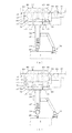
図4(a)、(b)に示すように、エレクタ受け渡し用ホイスト17は、ホイスト用レール16に沿って走行する第1走行部37と、第1走行部37に昇降自在に吊設され下方に延びるセグメント把持棒38と、セグメント把持棒38が所定高さに上昇されたときセグメント把持棒38を第1走行部37に保持する保持機構39とを備えて構成されている。所定高さとは、エレクタ(図示せず)にセグメント8を直接受け渡すときの高さであり、この高さでセグメント把持棒38を第1走行部37に保持することにより、セグメント8を揺らすことなく確実にエレクタに受け渡すことができる。   As shown in FIGS. 4A and 4B, the erector delivery hoist 17 has a first traveling portion 37 that travels along the hoist rail 16, and is suspended below the first traveling portion 37 so as to be movable up and down. And a holding mechanism 39 for holding the segment gripping bar 38 on the first traveling portion 37 when the segment gripping bar 38 is raised to a predetermined height. The predetermined height is the height when the segment 8 is directly delivered to an erector (not shown), and the segment gripping bar 38 is held at the first traveling portion 37 at this height, thereby swinging the segment 8. Without fail, it can be delivered to the erector without fail.

特開2008−163566号公報JP 2008-163666 A

しかしながら、エレクタ受け渡し用ホイスト17はセグメント8を上記所定高さを越えて上昇させることはできないため、図5に示すように、径方向内側に突起を有する等、通常のセグメント8より桁厚が厚い特殊なセグメント9を搬送する場合、形状保持装置15を越えられず、エレクタ(図示せず)まで搬送できないという課題があった。   However, since the hoist 17 for delivering the erector cannot raise the segment 8 beyond the predetermined height, the girders are thicker than the normal segment 8 as shown in FIG. When the special segment 9 is transported, there is a problem in that it cannot pass through the shape holding device 15 and cannot be transported to an erector (not shown).

そこで、本発明の目的は、上記課題を解決し、桁厚が厚い特殊セグメントであっても形状保持装置の前方に移送でき、かつ、エレクタ受け渡し用ホイストからエレクタに特殊セグメントを空中受け渡しにて供給できるシールド掘進機を提供することにある。   Therefore, the object of the present invention is to solve the above-mentioned problems, and even a special segment with a large girder thickness can be transferred to the front of the shape holding device, and the special segment is supplied to the erector from the erector delivery hoist by air delivery. It is to provide a shield machine that can be used.

上記課題を解決するために本発明は、シールドフレーム内でセグメントを組み立てるエレクタと、該エレクタでセグメントを組み立てて構築されるトンネル壁の上部内面と下部内面を押圧する形状保持装置と、該形状保持装置の掘進方向後方の位置から上記エレクタの位置まで走行自在な第1走行部を有すると共に上記エレクタにセグメントを空中にて直接受け渡すべくセグメントを吊持する剛体を有し、該剛体がセグメントを所定高さに吊り上げたとき上記第1走行部に保持されるようにしたエレクタ受け渡し用ホイストとを備えたシールド掘進機において、上記形状保持装置の前後に亘って走行自在な第2走行部を有すると共にセグメントを上記所定高さより上方に吊り上げ可能なセグメント吊り装置を有し、上記エレクタ受け渡し用ホイストにセグメントを供給するための中継用ホイストを備えたものである。   In order to solve the above-described problems, the present invention provides an erector that assembles a segment in a shield frame, a shape holding device that presses an upper inner surface and a lower inner surface of a tunnel wall constructed by assembling the segment with the erector, and the shape holding A first traveling portion that can freely travel from a position in the rearward direction of the apparatus to the position of the erector, and a rigid body that suspends the segment so that the segment can be directly delivered to the erector in the air. In a shield machine equipped with an hoist for delivering an erector that is held by the first traveling unit when lifted to a predetermined height, the shield machine has a second traveling unit that can travel across the shape holding device. And a segment suspension device capable of lifting the segment above the predetermined height, Those having a relay hoist for supplying segment strike.

シールドフレームに設けられ径方向内側に延びる支持フレームと、該支持フレームに掘進方向後方に延びて設けられた後方デッキと、該後方デッキに前後に延びて設けられ上記エレクタ受け渡し用ホイストを走行させるホイスト用レールとを備え、上記中継用ホイストが上記エレクタ受け渡し用ホイストの後方の上記ホイスト用レールに走行自在に設けられるとよい。   A support frame provided on the shield frame and extending inward in the radial direction; a rear deck provided on the support frame extending rearward in the digging direction; and a hoist extending forward and backward on the rear deck and running the above-mentioned erector delivery hoist The relay hoist is preferably provided on the hoist rail behind the erector delivery hoist so as to run freely.

上記トンネル壁の下部内面には後方から送られるセグメントを仮置きするための仮置き部が配設され、上記ホイスト用レールが上記仮置き部の後方まで延びる後端部を有し、該後端部に上記中継用ホイストを待機させるための待機部が形成されるとよい。   A temporary placement portion for temporarily placing a segment sent from the rear is disposed on the lower inner surface of the tunnel wall, and the hoist rail has a rear end portion extending to the rear of the temporary placement portion, the rear end It is preferable that a standby unit for allowing the relay hoist to stand by is formed in the unit.

上記エレクタ受け渡し用ホイストと上記中継用ホイストの少なくともいずれか一方のホイストに設けられ他方のホイストを検出する近接センサと、該近接センサに接続されると共に上記両方のホイストに接続され近接センサが上記他方のホイストを検出したとき両方のホイストを停止させる制御装置とを備えるとよい。   A proximity sensor that is provided on at least one of the above-described hoist for delivering the elector and the relay hoist, and that detects the other hoist, and is connected to the proximity sensor and connected to both the hoists, and the proximity sensor is connected to the other hoist. And a control device that stops both hoists when the hoist is detected.

本発明によれば、桁厚が厚い特殊セグメントであっても形状保持装置の前方に移送でき、かつ、エレクタ受け渡し用ホイストからエレクタに特殊セグメントを空中受け渡しにて供給できる。   According to the present invention, even a special segment having a thick girder can be transferred to the front of the shape holding device, and the special segment can be supplied to the erector from the erector delivery hoist by air delivery.

図1はシールド掘進機の概略側面図である。FIG. 1 is a schematic side view of a shield machine. 図2は中継用ホイストの側面図である。FIG. 2 is a side view of the relay hoist. 図3は形状保持装置を越えてセグメントを搬送する中継用ホイストの正面図である。FIG. 3 is a front view of a relay hoist that conveys a segment beyond the shape holding device. 図4(a)はセグメント搬送中のエレクタ受け渡し用ホイストの側面図であり、図4(b)はセグメントを把持する前のエレクタ受け渡し用ホイストの側面図である。FIG. 4A is a side view of the erector delivery hoist during segment conveyance, and FIG. 4B is a side view of the erector delivery hoist before gripping the segment. 図5は特殊セグメントを形状保持装置の前方に搬送できないエレクタ受け渡し用ホイストを説明するための説明図である。FIG. 5 is an explanatory diagram for explaining an erector delivery hoist that cannot convey a special segment to the front of the shape holding device.

図1に示すように、シールド掘進機1は、機体外周部を構成するシールドフレーム2と、シールドフレーム2の前端を塞ぐ隔壁3と、隔壁3に回転自在に設けられ前方の地山を掘削するカッタ4と、カッタ4と隔壁3の間に形成され土砂を収容するカッタ室5と、隔壁3に前方に貫通して設けられカッタ室5内の土砂を取り込む排土装置たるスクリューコンベア6と、シールドフレーム2に設けられ径方向内側に延びる支持フレーム7と、支持フレーム7に設けられシールドフレーム2内でセグメント8、9を組み立てるエレクタ10と、支持フレーム7に掘進方向後方に延びて設けられた後方デッキ11と、後方デッキ11に設けられセグメント8、9を組み立てて構築されるトンネル壁12の上部内面13と下部内面14を径方向外方に押す形状保持装置15と、後方デッキ11に設けられ形状保持装置15の前後に延びるホイスト用レール16と、ホイスト用レール16に走行自在に設けられセグメント8、9をエレクタ10に受け渡すためのエレクタ受け渡し用ホイスト17と、エレクタ受け渡し用ホイスト17の後方のホイスト用レール16に走行自在に設けられ桁厚の厚い特殊セグメント9を形状保持装置15の後方から前方に移送してエレクタ受け渡し用ホイスト17に供給するための中継用ホイスト18とを備えて構成される。   As shown in FIG. 1, the shield machine 1 excavates a ground frame forwardly provided on a shield frame 2 that forms the outer periphery of the fuselage, a partition wall 3 that closes the front end of the shield frame 2, and a partition wall 3 that is freely rotatable. A cutter 4, a cutter chamber 5 formed between the cutter 4 and the partition wall 3 and containing earth and sand; a screw conveyor 6 provided through the partition wall 3 as a soil removal device that passes through the partition wall 3 and takes in the earth and sand in the cutter chamber 5; A support frame 7 provided on the shield frame 2 and extending inward in the radial direction, an erector 10 provided on the support frame 7 for assembling the segments 8 and 9 in the shield frame 2, and provided on the support frame 7 extending rearward in the digging direction. The upper inner surface 13 and the lower inner surface 14 of the tunnel wall 12 that is constructed by assembling the rear deck 11 and the segments 8 and 9 provided on the rear deck 11 are radially outward. The shape retaining device 15, the hoist rail 16 provided on the rear deck 11 extending in the front and rear of the shape retaining device 15, and the erector for passing the segments 8, 9 provided on the hoist rail 16 to the erector 10. The hoist 17 for transfer and the hoist rail 16 on the rear side of the hoist 17 for ejector transfer are provided so as to run freely, and the special segment 9 having a thick girder thickness is transferred from the rear to the front of the shape holding device 15 to the hoist 17 for transfer of the elector. A relay hoist 18 for supply is provided.

エレクタ10は、支持フレーム7にシールドフレーム2と同軸上で回転するように設けられたリング状の旋回フレーム19と、旋回フレーム19に径方向に移動可能に設けられた吊りビーム20と、吊りビーム20に設けられセグメント8、9を把持する第1セグメント把持部21とを備えて構成されている。   The erector 10 includes a ring-shaped swivel frame 19 provided on the support frame 7 so as to rotate coaxially with the shield frame 2, a suspension beam 20 provided on the swivel frame 19 so as to be movable in the radial direction, and a suspension beam. 20 and a first segment gripping portion 21 that grips the segments 8 and 9.

後方デッキ11は、長尺の鋼材を箱状に組み付けて構成されており、シールドフレーム2の中心に配置されている。後方デッキ11の後端近傍のトンネル壁12の下部内面14には、後方から送られるセグメント8、9を仮置きするための仮置き部22が配設されている。仮置き部22は、形状保持装置15の後方のトンネル壁12の下部内面14に走行可能に設けられセグメント8、9を複数前後に並べてストックするセグメント搬送装置23の後端部に形成される。   The rear deck 11 is configured by assembling a long steel material in a box shape, and is arranged at the center of the shield frame 2. On the lower inner surface 14 of the tunnel wall 12 near the rear end of the rear deck 11, a temporary placement portion 22 for temporarily placing the segments 8 and 9 sent from the rear is disposed. The temporary placement unit 22 is formed on the lower end inner surface 14 of the tunnel wall 12 behind the shape holding device 15 so as to be able to run, and is formed at the rear end portion of the segment transfer device 23 that stocks a plurality of segments 8 and 9 arranged in the front and rear direction.

セグメント搬送装置23は、既設セグメント8上に敷設された仮設レール24上に走行自在に設けられ前後に延びるベース部25と、ベース部25上に昇降自在に、かつ、長手方向に沿って複数設けられセグメント8、9を載置するためのリフトアップ部26と、ベース部25上に前後スライド可能に設けられそれぞれのリフトアップ部26が下降されたときセグメント8、9を一括して受けるスライド部(図示せず)とを備える。セグメント搬送装置23は、セグメント8、9を載せたスライド部を前進させた後、リフトアップ部26を上昇さてリフトアップ部26にセグメント8、9を移載し、スライド部を後退させ、リフトアップ部26を下降させてセグメント8、9をスライド部に受け渡す動作を繰り返すことで、セグメント8、9を順次前方に送るようになっている。   The segment conveying device 23 is provided on a temporary rail 24 laid on the existing segment 8 so as to be able to run and extend in the front-rear direction, and can be moved up and down on the base portion 25 and provided in a plurality along the longitudinal direction. A lift-up portion 26 for placing the segments 8 and 9 and a slide portion provided on the base portion 25 so as to be slidable back and forth and receiving the segments 8 and 9 collectively when the lift-up portions 26 are lowered. (Not shown). The segment transport device 23 advances the slide portion on which the segments 8 and 9 are placed, then lifts the lift-up portion 26 to transfer the segments 8 and 9 to the lift-up portion 26, retracts the slide portion, and lifts up. By repeating the operation of lowering the portion 26 and delivering the segments 8 and 9 to the slide portion, the segments 8 and 9 are sequentially sent forward.

また、後方デッキ11の上端後部には、後方に延びる後方レール27が設けられており、後方から仮置き部22にセグメント8、9を搬送するための搬送用ホイスト28を後方レール27に沿って走行させるようになっている。   Further, a rear rail 27 extending rearward is provided at the rear upper end of the rear deck 11, and a transport hoist 28 for transporting the segments 8 and 9 from the rear to the temporary placement portion 22 is provided along the rear rail 27. It is designed to run.

図2及び図3に示すように、形状保持装置15は、上下方向に拡張する上下フレーム29a、29b間に上下フレーム29a、29bを拡縮する拡縮ジャッキ30を設けて構成されており、拡縮ジャッキ30を伸張させて上下フレーム29a、29bでトンネル壁12の上部内面13と下部内面14を径方向外方に押圧することでトンネル壁12の形状を保持するようになっている。下部フレーム29bは、略U字状に形成されており、下部にトンネル壁12に当接される円弧状の押圧部31を有する。上部フレーム29aは、下部フレーム29bを略上下反転させた形状(逆U字状)に形成されている。また、上部フレーム29には、拡縮ジャッキ30を縮退させて上部フレーム29aを下降させたとき後方デッキ11のレール32上に載置される車輪33が設けられると共に、一端が後方デッキ11に連結される走行用ジャッキ34の他端が連結されており、上下フレーム29a、29bがトンネル壁12から離間したとき走行用ジャッキ34を伸縮することで後方デッキ11のレール32上で上下フレーム29a、29bを走行させるようになっている。   As shown in FIGS. 2 and 3, the shape holding device 15 is configured by providing an expansion / contraction jack 30 for expanding / contracting the upper and lower frames 29 a, 29 b between the upper and lower frames 29 a, 29 b expanding in the vertical direction. The shape of the tunnel wall 12 is held by pressing the upper inner surface 13 and the lower inner surface 14 of the tunnel wall 12 radially outward with the upper and lower frames 29a and 29b. The lower frame 29b is formed in a substantially U shape, and has an arcuate pressing portion 31 that is in contact with the tunnel wall 12 at the lower portion. The upper frame 29a is formed in a shape (inverted U shape) obtained by inverting the lower frame 29b substantially vertically. Further, the upper frame 29 is provided with wheels 33 that are placed on the rails 32 of the rear deck 11 when the expansion jack 30 is retracted and the upper frame 29 a is lowered, and one end is connected to the rear deck 11. The other end of the traveling jack 34 is connected, and when the upper and lower frames 29a, 29b are separated from the tunnel wall 12, the traveling jack 34 is expanded and contracted so that the upper and lower frames 29a, 29b are moved on the rail 32 of the rear deck 11. It is designed to run.

図1及び図5に示すように、ホイスト用レール16は、後方デッキ11の両側下面にエレクタ10の前方に延びると共に後方デッキ11の後方に延出して設けられている。ホイスト用レール16は、断面I型に形成されており、下端に側方に延出する鍔部35を有する。ホイスト用レール16の後端部には、中継用ホイスト18を待機させるための待機部36が形成されている。待機部36は、仮置き部22より後方のホイスト用レール16に形成される。   As shown in FIGS. 1 and 5, the hoist rails 16 are provided on the lower surfaces of both sides of the rear deck 11 so as to extend forward of the erector 10 and to extend rearward of the rear deck 11. The hoist rail 16 has an I-shaped cross section, and has a flange portion 35 extending laterally at the lower end. At the rear end portion of the hoist rail 16, a standby portion 36 for waiting the relay hoist 18 is formed. The standby unit 36 is formed on the hoist rail 16 behind the temporary storage unit 22.

図1及び図4(a)、(b)に示すように、エレクタ受け渡し用ホイスト17は、ホイスト用レール16に走行自在に設けられ形状保持装置15の掘進方向後方の位置、具体的には仮置き部22とエレクタ10との間で走行する第1走行部37と、第1走行部37に昇降自在に吊設されエレクタ10にセグメント8、9を空中にて直接受け渡すべくセグメント8、9を吊持する剛体からなるセグメント把持棒38と、セグメント把持棒38が所定高さに上昇されたときセグメント把持棒38を第1走行部37に保持する保持機構39とを備える。第1走行部37は、ホイスト用レール16の鍔部35上を走行する支持用車輪40と、鍔部35の下面に押圧され駆動装置41で駆動される駆動輪42とを有する。また、第1走行部37には、セグメント把持棒38をワイヤ43を介して昇降自在に吊る吊上装置44が設けられている。セグメント把持棒38は、ワイヤ43に係合されるプーリ45を有し吊上装置44にワイヤ43を介して吊持される板状の昇降基部46と、昇降基部46に下方に延びて設けられる棒状の垂下部47と、垂下部47の下端部に設けられセグメント8、9の取っ手48を把持する把持装置49と、垂下部47に設けられセグメント8、9の側面に当接してセグメント8、9を支持する支持アーム50とを備える。保持機構39は、第1走行部37の下面に形成され昇降基部46を収容するように窪む凹部51と、昇降基部46の外縁に上方に突出して設けられ昇降基部46が凹部51に収容されたとき凹部51の縁部に嵌合されるテーパ部材52とからなる。   As shown in FIGS. 1, 4 (a), and 4 (b), the erector delivery hoist 17 is provided on the hoist rail 16 so as to be able to travel, and is located at the rear of the shape holding device 15 in the digging direction. A first traveling unit 37 that travels between the placing unit 22 and the erector 10, and segments 8, 9 that are suspended from the first traveling unit 37 so as to be able to move up and down and directly deliver the segments 8, 9 to the erector 10 in the air. And a holding mechanism 39 for holding the segment gripping bar 38 on the first traveling portion 37 when the segment gripping bar 38 is raised to a predetermined height. The first traveling portion 37 includes a support wheel 40 that travels on the flange portion 35 of the hoist rail 16 and a drive wheel 42 that is pressed by the lower surface of the flange portion 35 and driven by the drive device 41. Further, the first traveling unit 37 is provided with a lifting device 44 that hangs the segment gripping rod 38 via a wire 43 so as to be lifted and lowered. The segment gripping bar 38 has a pulley 45 that is engaged with the wire 43, a plate-like lifting base 46 that is suspended by the lifting device 44 via the wire 43, and is provided extending downward on the lifting base 46. A rod-like hanging portion 47; a gripping device 49 provided at the lower end portion of the hanging portion 47; and gripping a handle 48 of the segments 8, 9, and a segment 8, 9 and a support arm 50 that supports 9. The holding mechanism 39 is formed on the lower surface of the first traveling portion 37 and is recessed so as to accommodate the elevating base 46, and is provided to project upward on the outer edge of the elevating base 46. The elevating base 46 is accommodated in the concave 51. And a taper member 52 fitted to the edge of the recess 51.

また、エレクタ受け渡し用ホイスト17には、中継用ホイスト18が所定距離以内に接近したとき中継用ホイスト18を検出して制御装置53に信号を発する第1近接センサ54が設けられている。制御装置53は、第1近接センサ54から信号を受けたとき、中継用ホイスト18とエレクタ受け渡し用ホイスト17との両方を停止させるようにプログラムされている。   The erector delivery hoist 17 is provided with a first proximity sensor 54 that detects the relay hoist 18 and sends a signal to the control device 53 when the relay hoist 18 approaches within a predetermined distance. The control device 53 is programmed to stop both the relay hoist 18 and the erector delivery hoist 17 when receiving a signal from the first proximity sensor 54.

図2及び図3に示すように、中継用ホイスト18は、それぞれのホイスト用レール16に走行自在に設けられ形状保持装置15の前後に亘って走行自在な一対の第2走行部55と、これら第2走行部55に設けられ特殊セグメント9を上記所定高さより上方、すなわち、エレクタ10にセグメント8、9を受け渡す高さより上方に吊り上げ可能なセグメント吊り装置56とからなる。セグメント吊り装置56は、それぞれの第2走行部55に設けられたチェーンブロック57と、これらチェーンブロック57に昇降自在に吊り下げられる第1フック58と、これら第1フック58に着脱自在に係合され第1フック58間に掛け渡される連結部材59と、連結部材59にチェーン60を介して連結され特殊セグメント9に着脱自在に係合される第2フック61とからなる。また、中継用ホイスト18には、エレクタ受け渡し用ホイスト17が所定距離以内に接近したときエレクタ受け渡し用ホイスト17を検出して制御装置53に信号を発する第2近接センサ62が設けられている。制御装置53は、第2近接センサ62から信号を受けたとき、中継用ホイスト18とエレクタ受け渡し用ホイスト17との両方を停止させるようにプログラムされている。   As shown in FIGS. 2 and 3, the relay hoist 18 includes a pair of second traveling portions 55 that are provided on the hoist rails 16 so as to be able to travel over the front and rear of the shape holding device 15. A segment suspension device 56 provided in the second traveling portion 55 is capable of lifting the special segment 9 above the predetermined height, that is, above the height at which the segments 8 and 9 are delivered to the erector 10. The segment suspension device 56 includes a chain block 57 provided in each second traveling portion 55, a first hook 58 suspended from the chain block 57 so as to be movable up and down, and a detachable engagement with the first hook 58. The connecting member 59 spans between the first hooks 58 and the second hook 61 is connected to the connecting member 59 via the chain 60 and is detachably engaged with the special segment 9. The relay hoist 18 is provided with a second proximity sensor 62 that detects the erector delivery hoist 17 and issues a signal to the control device 53 when the erector delivery hoist 17 approaches within a predetermined distance. The control device 53 is programmed to stop both the relay hoist 18 and the erector delivery hoist 17 when receiving a signal from the second proximity sensor 62.

次に本実施の形態の作用を述べる。   Next, the operation of this embodiment will be described.

セグメント8、9を吊持した搬送用ホイスト28が仮置き部22の真上に到達したら仮置き部22にセグメント8、9を降ろす。このとき中継用ホイスト18は仮置き部22の後方の待機部36に待機させておき、搬送用ホイスト28から降ろされるセグメント8、9に干渉しないようにする。仮置き部22を形成するセグメント搬送装置23は、前端に位置されるリフトアップ部26上に常にセグメント8、9が供給されるようにセグメント8、9を順次前方のリフトアップ部26上に送る。   When the transport hoist 28 suspending the segments 8 and 9 reaches just above the temporary placement portion 22, the segments 8 and 9 are lowered to the temporary placement portion 22. At this time, the relay hoist 18 is made to wait in the standby unit 36 behind the temporary storage unit 22 so as not to interfere with the segments 8 and 9 that are lowered from the transport hoist 28. The segment conveying device 23 that forms the temporary placement unit 22 sequentially sends the segments 8 and 9 onto the front lift-up unit 26 so that the segments 8 and 9 are always supplied onto the lift-up unit 26 positioned at the front end. .

前端に位置されるリフトアップ部26上のセグメントが桁厚の薄い通常のセグメント8である場合、セグメント8は、エレクタ受け渡し用ホイスト17により前方に送られ、エレクタ10に受け渡される。具体的には、エレクタ受け渡し用ホイスト17は、セグメント搬送装置23の前端に位置されるリフトアップ部26の真上に到達したら、セグメント把持棒38を下降させ、セグメント把持棒38の把持装置49でリフトアップ部26上のセグメント8を把持し、セグメント把持棒38を上昇させる。セグメント把持棒38が所定高さに上昇すると、セグメント把持棒38の昇降基部46が凹部51内に収容され、テーパ部材52が凹部51の縁部に嵌合されて昇降基部46が前後左右方向に動かないように凹部51に保持される。この後、エレクタ受け渡し用ホイスト17は前方に走行しエレクタ10にセグメント8を空中にて直接受け渡す。このとき、エレクタ受け渡し用ホイスト17に把持されたセグメント8は、形状保持装置15の押圧部31より上方にあるため、押圧部31に干渉することはない。   When the segment on the lift-up part 26 located at the front end is a normal segment 8 having a thin girder thickness, the segment 8 is forwarded by the elector delivery hoist 17 and delivered to the erector 10. Specifically, when the erector delivery hoist 17 reaches directly above the lift-up unit 26 positioned at the front end of the segment conveying device 23, the segment gripping rod 38 is lowered and the segment gripping rod 38 gripping device 49 is used. The segment 8 on the lift-up part 26 is gripped and the segment gripping bar 38 is raised. When the segment gripping bar 38 is raised to a predetermined height, the lifting base 46 of the segment gripping bar 38 is accommodated in the recess 51, the taper member 52 is fitted to the edge of the recess 51, and the lifting base 46 is moved in the front-rear and left-right directions. It is held in the recess 51 so as not to move. Thereafter, the erector delivery hoist 17 travels forward and delivers the segment 8 directly to the erector 10 in the air. At this time, the segment 8 gripped by the erector delivery hoist 17 is above the pressing portion 31 of the shape holding device 15, and therefore does not interfere with the pressing portion 31.

また、前端に位置されるリフトアップ部26上に通常のセグメント8より桁厚が厚い特殊セグメント9が載置された場合、特殊セグメント9は、中継用ホイスト18により形状保持装置15の前方に移送され、エレクタ受け渡し用ホイスト17に供給され、エレクタ受け渡し用ホイスト17を介してエレクタ10に受け渡される。具体的には、エレクタ受け渡し用ホイスト17を、予め形状保持装置15の前方に退避させ、中継用ホイスト18を待機部36から前方に走行させる。中継用ホイスト18がセグメント搬送装置23の前端に位置されるリフトアップ部26の真上に到達したら、それぞれのチェーンブロック57からチェーンを繰り出して第2フック61を下降させ、リフトアップ部26上の特殊セグメント9に第2フック61を掛け、それぞれのチェーンブロック57を巻き上げて特殊セグメント9を形状保持装置15の押圧部31より上方に上昇させる。この後、中継用ホイスト18を前方に走行させ、特殊セグメント9が形状保持装置15の押圧部31を越えたら特殊セグメント9を下降させて既設セグメント8上に置く。このとき、中継用ホイスト18がエレクタ受け渡し用ホイスト17に所定距離を超えて接近したら、中継用ホイスト18又はエレクタ受け渡し用ホイスト17に設けられた近接センサ54、62が制御装置53に信号を発し、制御装置53が中継用ホイスト18とエレクタ受け渡し用ホイスト17の両方を停止させるため、中継用ホイスト18とエレクタ受け渡し用ホイスト17が衝突することはない。この後、中継用ホイスト18を待機部36に走行させると共に、エレクタ受け渡し用ホイスト17を既設セグメント8上に置いた特殊セグメント9の真上に走行させ、この特殊セグメント9をエレクタ受け渡し用ホイスト17で把持すると共に所定高さに上昇させ、エレクタ受け渡し用ホイスト17をエレクタ10の位置に走行させ、エレクタ受け渡し用ホイスト17からエレクタ10に特殊セグメント9を空中にて直接受け渡す。   Further, when the special segment 9 having a thickness larger than that of the normal segment 8 is placed on the lift-up portion 26 positioned at the front end, the special segment 9 is transferred to the front of the shape holding device 15 by the relay hoist 18. Then, it is supplied to the erector delivery hoist 17 and delivered to the erector 10 via the erector delivery hoist 17. Specifically, the erector delivery hoist 17 is retracted in front of the shape retaining device 15 in advance, and the relay hoist 18 is caused to travel forward from the standby unit 36. When the relay hoist 18 reaches directly above the lift-up part 26 positioned at the front end of the segment conveying device 23, the chain is unwound from each chain block 57 to lower the second hook 61, and the lift-up part 26 The second hook 61 is hung on the special segment 9, and each chain block 57 is wound up to raise the special segment 9 above the pressing portion 31 of the shape holding device 15. Thereafter, the relay hoist 18 is moved forward, and when the special segment 9 exceeds the pressing portion 31 of the shape holding device 15, the special segment 9 is lowered and placed on the existing segment 8. At this time, when the relay hoist 18 approaches the elector delivery hoist 17 beyond a predetermined distance, the proximity sensors 54 and 62 provided on the relay hoist 18 or the elector delivery hoist 17 send a signal to the control device 53, Since the control device 53 stops both the relay hoist 18 and the erector delivery hoist 17, the relay hoist 18 and the erector delivery hoist 17 do not collide. Thereafter, the relay hoist 18 is caused to travel to the standby portion 36, and the erector delivery hoist 17 is caused to travel directly above the special segment 9 placed on the existing segment 8, and this special segment 9 is moved by the erector delivery hoist 17. While gripping and raising to a predetermined height, the hoist 17 for delivering the erector is moved to the position of the erector 10, and the special segment 9 is directly delivered from the erector delivering hoist 17 to the erector 10 in the air.

このように、形状保持装置15の前後に亘って走行自在な第2走行部55を有すると共に特殊セグメント9を所定高さより上方に吊り上げ可能なセグメント吊り装置56を有し、エレクタ受け渡し用ホイスト17に特殊セグメント9を供給するための中継用ホイスト18を備えたため、エレクタ受け渡し用ホイスト17では形状保持装置15を越えることができない桁厚が厚い特殊セグメント9であっても形状保持装置15の前方に移送でき、かつ、エレクタ受け渡し用ホイスト17からエレクタ10に特殊セグメント9を空中受け渡しにて供給できる。   In this way, it has the second traveling part 55 that can travel over the front and rear of the shape holding device 15 and has the segment suspension device 56 that can lift the special segment 9 above a predetermined height. Since the relay hoist 18 for supplying the special segment 9 is provided, even if the special segment 9 has a thick girder thickness that cannot be exceeded by the shape holding device 15 with the erector delivery hoist 17, it is transferred to the front of the shape holding device 15. In addition, the special segment 9 can be supplied from the erector delivery hoist 17 to the erector 10 by air delivery.

シールドフレーム2に設けられ径方向内側に延びる支持フレーム7と、支持フレーム7に掘進方向後方に延びて設けられた後方デッキ11と、後方デッキ11に前後に延びて設けられエレクタ受け渡し用ホイスト17を走行させるホイスト用レール16とを備え、中継用ホイスト18がエレクタ受け渡し用ホイスト17の後方のホイスト用レール16に走行自在に設けられるものとしたため、簡単な構造で容易に特殊セグメント9を形状保持装置15の前方に移送できる。   A support frame 7 provided on the shield frame 2 and extending inward in the radial direction; a rear deck 11 provided on the support frame 7 extending rearward in the digging direction; and an erector delivery hoist 17 provided extending forward and rearward on the rear deck 11 Since the hoist rail 16 is provided and the relay hoist 18 is provided on the hoist rail 16 behind the elevator hoist 17 so as to be able to run, the special segment 9 can be easily shaped with a simple structure. 15 forward.

トンネル壁12の下部内面14には後方から送られるセグメント8、9を仮置きするための仮置き部22が配設され、ホイスト用レール16が仮置き部22の後方まで延びる後端部を有し、この後端部に中継用ホイスト18を待機させるための待機部36が形成されるものとしたため、セグメント8、9を仮置き部22に搬送するとき中継用ホイスト18がセグメント搬送の邪魔になるのを簡単な構造で容易に防ぐことができる。   The lower inner surface 14 of the tunnel wall 12 is provided with a temporary placement portion 22 for temporarily placing the segments 8 and 9 sent from the rear, and the hoist rail 16 has a rear end portion extending to the rear of the temporary placement portion 22. Since the standby portion 36 for waiting the relay hoist 18 is formed at the rear end portion, when the segments 8 and 9 are transported to the temporary placement portion 22, the relay hoist 18 interferes with the segment transport. This can be easily prevented with a simple structure.

エレクタ受け渡し用ホイスト17と中継用ホイスト18の一方のホイストに設けられ他方のホイストを検出する近接センサ54、62と、近接センサ54、62に接続されると共に両方のホイスト17、18に接続され近接センサ54、62が他方のホイストを検出したとき両方のホイスト17、18を停止させる制御装置53とを備えたため、エレクタ受け渡し用ホイスト17と中継用ホイスト18との衝突を確実に防ぐことができる。   Proximity sensors 54 and 62 for detecting the other hoist provided on one of the hoists 17 for the ejector transfer and the relay hoist 18, and connected to the proximity sensors 54 and 62 and connected to both hoists 17 and 18 for proximity Since the control device 53 is provided to stop both hoists 17 and 18 when the sensors 54 and 62 detect the other hoist, the collision between the erector delivery hoist 17 and the relay hoist 18 can be reliably prevented.

なお、エレクタ受け渡し用ホイスト17に第1近接センサ54を設け、中継用ホイスト18に第2近接センサ62を設けるものとしたが、近接センサ54、62はエレクタ受け渡し用ホイスト17又は中継用ホイスト18のいずれか一方にのみ設けられるものとしてもよい。   Although the first proximity sensor 54 is provided on the erector delivery hoist 17 and the second proximity sensor 62 is provided on the relay hoist 18, the proximity sensors 54, 62 are connected to the erector delivery hoist 17 or the relay hoist 18. It is good also as what is provided only in either one.

1 シールド掘進機
2 シールドフレーム
7 支持フレーム
8 セグメント
9 特殊セグメント
10 エレクタ
11 後方デッキ
12 トンネル壁
13 上部内面
14 下部内面
15 形状保持装置
16 ホイスト用レール
17 エレクタ受け渡し用ホイスト
18 中継用ホイスト
22 仮置き部
36 待機部
37 第1走行部
38 セグメント把持棒(剛体)
53 制御装置
54 第1近接センサ
55 第2走行部
56 セグメント吊り装置
62 第2近接センサ
DESCRIPTION OF SYMBOLS 1 Shield machine 2 Shield frame 7 Support frame 8 Segment 9 Special segment 10 Elector 11 Back deck 12 Tunnel wall 13 Upper inner surface 14 Lower inner surface 15 Shape holding device 16 Hoist rail 17 Elector delivery hoist 18 Relay hoist 22 Temporary placement part 36 Standby section 37 First traveling section 38 Segment gripping rod (rigid body)
53 Control Device 54 First Proximity Sensor 55 Second Traveling Unit 56 Segment Suspension Device 62 Second Proximity Sensor

Claims (4)

シールドフレーム内でセグメントを組み立てるエレクタと、該エレクタでセグメントを組み立てて構築されるトンネル壁の上部内面と下部内面を押圧する形状保持装置と、該形状保持装置の掘進方向後方の位置から上記エレクタの位置まで走行自在な第1走行部を有すると共に上記エレクタにセグメントを空中にて直接受け渡すべくセグメントを吊持する剛体を有し、該剛体がセグメントを所定高さに吊り上げたとき上記第1走行部に保持されるようにしたエレクタ受け渡し用ホイストとを備えたシールド掘進機において、上記形状保持装置の前後に亘って走行自在な第2走行部を有すると共にセグメントを上記所定高さより上方に吊り上げ可能なセグメント吊り装置を有し、上記エレクタ受け渡し用ホイストにセグメントを供給するための中継用ホイストを備えたことを特徴とするシールド掘進機。   An erector that assembles the segments in the shield frame, a shape holding device that presses the upper and lower inner surfaces of the tunnel wall that is constructed by assembling the segments with the erector, and a position of the erector A first traveling portion that can travel to a position, and a rigid body that suspends the segment to directly deliver the segment to the erector in the air, and the first body travels when the rigid body lifts the segment to a predetermined height. In a shield machine equipped with an hoist for delivering an erector that is held by a part, it has a second running part that can run across the shape holding device and can lift the segment above the predetermined height. A segment suspension device for supplying segments to the above-mentioned erector delivery hoist Shield machine characterized by comprising the following hoist. シールドフレームに設けられ径方向内側に延びる支持フレームと、該支持フレームに掘進方向後方に延びて設けられた後方デッキと、該後方デッキに前後に延びて設けられ上記エレクタ受け渡し用ホイストを走行させるホイスト用レールとを備え、上記中継用ホイストが上記エレクタ受け渡し用ホイストの後方の上記ホイスト用レールに走行自在に設けられた請求項1記載のシールド掘進機。   A support frame provided on the shield frame and extending inward in the radial direction; a rear deck provided on the support frame extending rearward in the digging direction; and a hoist extending forward and backward on the rear deck and running the above-mentioned erector delivery hoist The shield machine according to claim 1, further comprising: a rail, wherein the relay hoist is provided on the hoist rail behind the elevator hoist so as to run freely. 上記トンネル壁の下部内面には後方から送られるセグメントを仮置きするための仮置き部が配設され、上記ホイスト用レールが上記仮置き部の後方まで延びる後端部を有し、該後端部に上記中継用ホイストを待機させるための待機部が形成された請求項2記載のシールド掘進機。   A temporary placement portion for temporarily placing a segment sent from the rear is disposed on the lower inner surface of the tunnel wall, and the hoist rail has a rear end portion extending to the rear of the temporary placement portion, the rear end The shield machine according to claim 2, wherein a standby portion for allowing the relay hoist to wait is formed in the portion. 上記エレクタ受け渡し用ホイストと上記中継用ホイストの少なくともいずれか一方のホイストに設けられ他方のホイストを検出する近接センサと、該近接センサに接続されると共に上記両方のホイストに接続され近接センサが上記他方のホイストを検出したとき両方のホイストを停止させる制御装置とを備えた請求項1〜3のいずれかに記載のシールド掘進機。   A proximity sensor that is provided on at least one of the above-described hoist for delivering the elector and the relay hoist, and that detects the other hoist, and is connected to the proximity sensor and connected to both the hoists, and the proximity sensor is connected to the other hoist. The shield machine according to any one of claims 1 to 3, further comprising a control device that stops both hoists when the hoist is detected.
JP2009045914A 2009-02-27 2009-02-27 Shield machine Active JP5128520B2 (en)

Priority Applications (1)

Application Number Priority Date Filing Date Title
JP2009045914A JP5128520B2 (en) 2009-02-27 2009-02-27 Shield machine

Applications Claiming Priority (1)

Application Number Priority Date Filing Date Title
JP2009045914A JP5128520B2 (en) 2009-02-27 2009-02-27 Shield machine

Publications (2)

Publication Number Publication Date
JP2010196443A JP2010196443A (en) 2010-09-09
JP5128520B2 true JP5128520B2 (en) 2013-01-23

Family

ID=42821425

Family Applications (1)

Application Number Title Priority Date Filing Date
JP2009045914A Active JP5128520B2 (en) 2009-02-27 2009-02-27 Shield machine

Country Status (1)

Country Link
JP (1) JP5128520B2 (en)

Families Citing this family (3)

* Cited by examiner, † Cited by third party
Publication number Priority date Publication date Assignee Title
JP6241924B2 (en) * 2013-10-29 2017-12-06 株式会社奥村組 Shield digging machine and its digging method
JP6348296B2 (en) * 2014-02-20 2018-06-27 川崎重工業株式会社 Segment transport device
JP6918615B2 (en) * 2017-07-28 2021-08-11 川崎重工業株式会社 Shape retention device and shield excavator

Family Cites Families (5)

* Cited by examiner, † Cited by third party
Publication number Priority date Publication date Assignee Title
JP3147533B2 (en) * 1992-09-30 2001-03-19 石川島播磨重工業株式会社 Segment feeder
JP2732381B2 (en) * 1996-03-14 1998-03-30 鹿島建設株式会社 Scaffolding equipment for segment assembly work
JP3300223B2 (en) * 1996-03-26 2002-07-08 鹿島建設株式会社 Segment transport method and segment transport device
JP3924181B2 (en) * 2002-03-05 2007-06-06 三菱重工業株式会社 Segment supply device and tunnel excavator
JP4866770B2 (en) * 2007-03-28 2012-02-01 ジャパントンネルシステムズ株式会社 Segment conveying apparatus and segment conveying method

Also Published As

Publication number Publication date
JP2010196443A (en) 2010-09-09

Similar Documents

Publication Publication Date Title
TW201107221A (en) Article storage facility
CN104891195B (en) Copper ingot automatic stacking device
JP5128520B2 (en) Shield machine
JP5982327B2 (en) Tube unloading apparatus and tube unloading method
JP2009149422A (en) Exchanging device and method of elevator hoisting machine
CN107263190A (en) Long bar bearing material frame mechanism
JPH0892921A (en) Installing and recovering device for rubber cone
JP5133283B2 (en) Segment conveying method and segment conveying apparatus
CN105041240B (en) Floating marine drilling well marine riser cat road machine
CN209988518U (en) Feeding and conveying device suitable for cylindrical castings
JP4866770B2 (en) Segment conveying apparatus and segment conveying method
CN206244262U (en) Bearing cap finished product frame pallet
JP4551037B2 (en) Large-scale PC slab erection method and apparatus
JP2008030600A (en) Transportation vehicle and transporting method for pipe
JP4509875B2 (en) Material transfer system for building exterior wall construction
CN109465493B (en) Large-specification anchor chain bar blanking production line and feeding method
JPH03186510A (en) Transport facility using self-running device
KR200452876Y1 (en) Marine crane
JP2013087502A (en) Outer wall material fitting system
JP3950311B2 (en) Hanging conveyor
JPH0220319Y2 (en)
JP3884825B2 (en) Carrying system for lining segments for tunnel construction
CN104074480B (en) The device and method of mechanization workover treatment elevator transhipment
CN210263138U (en) Prefabricated piping lane installation car
JP3768609B2 (en) Hoop feeder

Legal Events

Date Code Title Description
A621 Written request for application examination

Free format text: JAPANESE INTERMEDIATE CODE: A621

Effective date: 20111108

A711 Notification of change in applicant

Free format text: JAPANESE INTERMEDIATE CODE: A712

Effective date: 20120510

A977 Report on retrieval

Free format text: JAPANESE INTERMEDIATE CODE: A971007

Effective date: 20121018

TRDD Decision of grant or rejection written
A01 Written decision to grant a patent or to grant a registration (utility model)

Free format text: JAPANESE INTERMEDIATE CODE: A01

Effective date: 20121023

A01 Written decision to grant a patent or to grant a registration (utility model)

Free format text: JAPANESE INTERMEDIATE CODE: A01

A61 First payment of annual fees (during grant procedure)

Free format text: JAPANESE INTERMEDIATE CODE: A61

Effective date: 20121031

R150 Certificate of patent or registration of utility model

Free format text: JAPANESE INTERMEDIATE CODE: R150

Ref document number: 5128520

Country of ref document: JP

Free format text: JAPANESE INTERMEDIATE CODE: R150

FPAY Renewal fee payment (event date is renewal date of database)

Free format text: PAYMENT UNTIL: 20151109

Year of fee payment: 3

R250 Receipt of annual fees

Free format text: JAPANESE INTERMEDIATE CODE: R250

R250 Receipt of annual fees

Free format text: JAPANESE INTERMEDIATE CODE: R250

S111 Request for change of ownership or part of ownership

Free format text: JAPANESE INTERMEDIATE CODE: R313111

S531 Written request for registration of change of domicile

Free format text: JAPANESE INTERMEDIATE CODE: R313531

R350 Written notification of registration of transfer

Free format text: JAPANESE INTERMEDIATE CODE: R350

R250 Receipt of annual fees

Free format text: JAPANESE INTERMEDIATE CODE: R250

R250 Receipt of annual fees

Free format text: JAPANESE INTERMEDIATE CODE: R250

R250 Receipt of annual fees

Free format text: JAPANESE INTERMEDIATE CODE: R250

R250 Receipt of annual fees

Free format text: JAPANESE INTERMEDIATE CODE: R250

R250 Receipt of annual fees

Free format text: JAPANESE INTERMEDIATE CODE: R250