JP5125164B2 - Fluid container - Google Patents
Fluid container Download PDFInfo
- Publication number
- JP5125164B2 JP5125164B2 JP2007072008A JP2007072008A JP5125164B2 JP 5125164 B2 JP5125164 B2 JP 5125164B2 JP 2007072008 A JP2007072008 A JP 2007072008A JP 2007072008 A JP2007072008 A JP 2007072008A JP 5125164 B2 JP5125164 B2 JP 5125164B2
- Authority
- JP
- Japan
- Prior art keywords
- fluid
- sealing
- housing
- ink
- fluid container
- Prior art date
- Legal status (The legal status is an assumption and is not a legal conclusion. Google has not performed a legal analysis and makes no representation as to the accuracy of the status listed.)
- Expired - Fee Related
Links
Images


Description
本発明は、インクカートリッジ等の流体収容容器及びその製造方法に関する。 The present invention relates to a fluid container such as an ink cartridge and a method for manufacturing the same.
従来、流体噴射ヘッドのノズルから液滴を噴射する流体噴射装置として、インクジェッ
ト式プリンタがある。このインクジェット式プリンタには、インクカートリッジをキャリ
ッジ以外の場所に搭載するオフキャリッジタイプのインク供給システムを備えるものがあ
る。このオフキャリッジタイプのインク供給システムを備える場合としては、大判印刷の
ために大容量のインクカートリッジを備える場合、及び、インクカートリッジを搭載しな
いことによりキャリッジを小型化し、インクジェット式プリンタを小型化、薄型化する場
合等がある。
2. Description of the Related Art Conventionally, there is an ink jet printer as a fluid ejecting apparatus that ejects droplets from a nozzle of a fluid ejecting head. Some ink jet printers include an off-carriage type ink supply system in which an ink cartridge is mounted at a place other than a carriage. The off-carriage type ink supply system includes a large-capacity ink cartridge for large-format printing, and the carriage is downsized by not mounting the ink cartridge, and the inkjet printer is downsized and thin. There are some cases.
このオフキャリッジタイプのインク供給システムでは、例えば、インクカートリッジを
本体側に配設する。そして、インクカートリッジから、インク供給チューブを介して、キ
ャリッジに搭載されたサブタンクまたは記録ヘッド等へインクを供給する。
In this off-carriage type ink supply system, for example, an ink cartridge is disposed on the main body side. Then, the ink is supplied from the ink cartridge to the sub tank or the recording head mounted on the carriage via the ink supply tube.
この種のインクカートリッジは、特許文献1等に開示されている。この種のインクカー
トリッジは、筐体内にインクパックを収容し、空きスペースに発泡スチロール等の弾性素
材を装填して、下ケースの開口を封止フィルムで封止した後に上ケースを固定している。
主として商業用に用いられて大量にインクが消費されるオフキャリッジタイプのインク
カートリッジは、交換頻度を低減するために大容量化が進みつつある。このため、相当重
量のインクカートリッジを落下させると、その重量の衝撃でインクカートリッジが破損し
やすくなる。インクパックの周囲には発泡スチロール等のスペーサ部材が配置されている
が、それだけではインクカートリッジの破損を防止し得ないほど、インクカートリッジの
大容量が進みつつある。
Off-carriage type ink cartridges, which are mainly used for commercial use and consume a large amount of ink, are increasing in capacity in order to reduce replacement frequency. For this reason, if an ink cartridge having a considerable weight is dropped, the ink cartridge is easily damaged by the impact of the weight. A spacer member such as a polystyrene foam is disposed around the ink pack. However, the capacity of the ink cartridge is increasing so that the ink cartridge cannot be damaged by itself.
そこで、本発明の目的は、落下等の衝撃に強い流体収容容器及びその製造方法を提供す
ることにある。
Accordingly, an object of the present invention is to provide a fluid container that is resistant to impacts such as dropping and a method for manufacturing the same.
本発明の一態様による流体収容容器は、
流体を収容する流体収容体と、
基端が前記流体収容体の前縁側に連結され、先端側に設けられた導出端部から前記流体収容体に収容された流体を外部に導出するための流体導出部材と、
前記流体導出部材が連結された前記流体収容体を収容する筐体と、を有する流体収容容器であって、
前記筐体の前側の壁部には、孔部が設けられ、
前記孔部には、環状のシール部材が装着され、
前記流体導出部材が連結された流体収容体は、前記流体導出部材の導出端部が前記シール部材に嵌合するように、前記筐体の内部に収容され、
前記流体導出部材の前記導出端部と前記基端との間には、前記導出端部側の第1面と基端側の第2面とを有するフランジ部が設けられており、
前記筐体の内部には、前記流体導出部材を挟むように、前記流体導出部材を支持するための一対のリブが設けられ、
前記一対のリブは、後端部から前端部に向うに従って狭くなるようにハの字状に形成されており、前記流体導出部材を前記リブの後端部から前端部に向かう第1方向に移動させて前記シール部材に嵌合させる際に前記第1方向と交差する方向に押し広げられ、前記流体導出部材が前記シール部材と嵌合する位置に達したときに弾性復帰して前記フランジ部の前記第2面と対向するように構成され、
前記フランジ部は、前記第1面が前記シール部材に対向し、前記第2面が前記リブの前記前端部に対向するように前記筐体内に配置されて、前記シール部材と前記リブの前記前端部とにより挟持され、
前記筐体の内部には、前記リブの後端部側に配置されて、前記リブの前記第1方向とは逆の第2方向への移動を規制する規制部材が設けられることを特徴とする。
A fluid storage container according to an aspect of the present invention includes:
A fluid container for containing a fluid;
A fluid lead-out member connected to the front edge side of the fluid container, and a fluid lead-out member for leading the fluid contained in the fluid container from the lead-out end provided on the tip side;
A fluid container having a housing for housing the fluid container to which the fluid outlet member is coupled,
A hole is provided in the front wall of the housing,
An annular seal member is attached to the hole,
The fluid container to which the fluid lead-out member is coupled is housed in the housing such that the lead-out end portion of the fluid lead-out member is fitted to the seal member,
Between the lead-out end portion and the base end of the fluid lead-out member, a flange portion having a first surface on the lead-out end portion side and a second surface on the base end side is provided,
Inside the housing, a pair of ribs for supporting the fluid outlet member is provided so as to sandwich the fluid outlet member,
The pair of ribs are formed in a square shape so as to become narrower from the rear end portion toward the front end portion, and the fluid outlet member moves in a first direction from the rear end portion of the rib toward the front end portion. When being fitted to the seal member, it is expanded in a direction crossing the first direction, and when the fluid lead-out member reaches a position where it is fitted with the seal member, it is elastically returned to the flange portion. Configured to face the second surface;
The flange portion is disposed in the housing such that the first surface faces the seal member and the second surface faces the front end portion of the rib, and the front end of the seal member and the rib Sandwiched between
A restriction member is provided inside the housing, and is disposed on the rear end side of the rib, and restricts movement of the rib in a second direction opposite to the first direction. .
本発明の一態様によれば、固定リブによる第1の方向と交差する方向への弾性変形・弾
性復帰機能を担保しながら、流体導出部材のフランジ部が第1の方向とは逆方向である第
2の方向へ後退する移動を、規制部材によって移動規制されて補強された固定リブによっ
て確実に防止できる。従って、流体収容袋体の容積が増大されて流体収容容器が大型化・
高重量化しても、落下等による衝撃によって固定リブが破損し、流体収容容器が破損して
しまうことを防止または抑制できる。
According to one aspect of the present invention, the flange portion of the fluid outlet member is in a direction opposite to the first direction while ensuring the elastic deformation / return function in the direction intersecting the first direction by the fixing rib. The movement backwardly moving in the second direction can be reliably prevented by the fixed rib reinforced by movement restriction by the restriction member. Therefore, the volume of the fluid storage bag is increased, and the fluid storage container is increased in size and
Even when the weight is increased, it is possible to prevent or suppress the fixing rib from being damaged by an impact caused by dropping or the like and the fluid storage container from being damaged.
本発明の一態様では、前記規制部材が、前記筐体とは別の部材により形成され、かつ、
前記筐体に対して位置決め支持されるものでもよい。筐体に規制部材を設けることも可能
であり、固定リブの後端と僅かな隙間をもって配置される規制部材を筐体と一体的に成形
しても良い。ただし、わずかな隙間を射出成形で製造するには金型に工夫を要するので、
筐体とは別部材で規制部材を形成することが好ましい。この場合、規制部材の取り付けは
、流体収容容器が固定リブに支持された後の工程となる。
In one aspect of the present invention, the restriction member is formed of a member different from the casing, and
It may be positioned and supported with respect to the housing. It is also possible to provide a restricting member on the housing, and the restricting member disposed with a slight gap from the rear end of the fixing rib may be formed integrally with the housing. However, in order to produce a slight gap by injection molding, the mold needs to be devised,
It is preferable to form the regulating member as a separate member from the casing. In this case, the attachment of the regulating member is a process after the fluid container is supported by the fixing rib.
本発明の一態様では、前記筐体は、前記前側の壁部と交わる底壁部と前記前側の壁部と対向する後側の壁部とを有し、かつ、前記底壁部と対向する面に開口を有し、前記筐体の前記開口が封止フィルムによって封止されることで、前記筐体の内部には外部から加圧流体が導入される加圧室が形成され、前記流体収容体は、前記底壁部と対向する第1面と、前記封止フィルムと対向する第2面と、前記流体導出部材が連結された第1封止部と、前記第1封止部に対向する第2封止部と、を有し、前記第1封止部が前記筐体の前側の壁部側、前記第2封止部が前記筐体の後側の壁部側となるように、前記加圧室内に収容され、前記流体収容体は、前記第1封止部から前記第2封止部に向かうに従い前記第1面と第2面との間の厚さが変化する厚さ変化領域を有し、 前記流体収容体の前記厚さ変化領域と前記封止フィルムとの間には、剛体であるスペーサ部材が配置され、前記規制部材は、前記スペーサ部材に一体的に形成されていることを特徴とする流体収ことが好ましい。これにより、スペーサ部材に形成された規制部材を、固定リブのストッパとして機能させることが可能となる。
In one aspect of the present invention, the housing includes a bottom wall portion that intersects with the front wall portion and a rear wall portion that faces the front wall portion, and faces the bottom wall portion. An opening is formed on the surface, and the opening of the casing is sealed with a sealing film, whereby a pressurized chamber into which a pressurized fluid is introduced from the outside is formed inside the casing. housing body includes a first surface that faces the bottom wall portion, a second surface opposite to the sealing film, a first sealing portion in which the fluid outlet member is connected to said first sealing portion An opposing second sealing portion , wherein the first sealing portion is a front wall portion side of the housing and the second sealing portion is a rear wall portion side of the housing. And the thickness of the fluid container is changed such that the thickness between the first surface and the second surface changes from the first sealing portion toward the second sealing portion. The Has a region, between the said thickness changing region sealing film of the fluid container is arranged a spacer member is rigid, the restricting member is formed integrally with the spacer member Preferably, the fluid is characterized by Thus, the regulating member formed on the spacer member, it is possible to function as a stopper for fixing ribs.
上記の態様では、前記スペーサ部材は、前面と、上面と、前記前面と上面とを結ぶ傾斜面とを有する断面の輪郭が略三角形を呈する部材であり、前記スペーサ部材は、前記上面が前記封止フィルムと対向し、前記傾斜面が前記流体収容体の前記厚さ変化領域と対向するように、前記加圧室内に配置されており、前記スペーサ部材の前記上面と、前記封止フィルムとの間に空間部が形成されていることが好ましい。このような空間部を確保することにより、内部の流体収容体の移動等の要因で、スペーサ部材が封止フィルムを破損させてしまう事故を低減することが可能となる。
In the above aspect, the spacer member is a member that has a front surface, an upper surface, and an inclined surface that connects the front surface and the upper surface, and has a substantially triangular outline, and the spacer member has the upper surface that is sealed. facing the stop film, wherein such inclined surface is opposed to said thickness changing region of the fluid container is disposed in said pressure chamber, said top surface of said spacer member, and the sealing film It is preferable that a space is formed between them. By securing such a space portion, it is possible to reduce an accident in which the spacer member damages the sealing film due to factors such as movement of the internal fluid container .
本発明の他の態様に係る流体収容容器は、上述した流体収容袋体と、流体導出部材と、
筐体と、封止フィルムと、シール部材とを有する他、上述した規制部材とは異なり、前記
流体導出部材の前記導出端部が、第1方向に移動されて前記シール部材に嵌合挿入された
状態で、前記フランジ部が前記第1方向とは逆方向の第2方向に移動することを規制する
規制部材を設けたことを特徴とする。
A fluid storage container according to another aspect of the present invention includes the above-described fluid storage bag, a fluid outlet member,
In addition to the housing member, the sealing film, and the seal member, the lead-out end portion of the fluid lead-out member is moved in the first direction and is inserted into the seal member. In this state, there is provided a restricting member that restricts the flange portion from moving in a second direction opposite to the first direction.
つまり、規制部材は移動規制対象のフランジ自体を直接規制しても良い。ただし、前記
規制部材が、前記筐体とは別の部材により形成され、かつ、前記筐体に対して位置決め支
持される必要がある。筐体に規制部材を設けると、フランジ部がシール部材に当接する過
程で互いに干渉するからである。
That is, the restricting member may directly restrict the flange itself subject to movement restriction. However, it is necessary that the restricting member is formed of a member different from the casing and is positioned and supported with respect to the casing. This is because when the restriction member is provided in the housing, the flange portions interfere with each other in the process of contacting the seal member.
本発明の他の態様では、固定リブは必ずしも必要ではない。規制部材によってフランジ
部を直接規制できるからである。ただし、流体収容袋体を筐体に装着した時のエンドスト
ッパとして機能させるために、固定リブを設けても良い。
In other aspects of the invention, the securing ribs are not necessary. This is because the flange portion can be directly regulated by the regulating member. However, a fixing rib may be provided in order to function as an end stopper when the fluid containing bag is attached to the housing.
また、本発明の他の態様においても、規制部材をスペーサ部材に形成することができ、
さらに、スペーサ部材が封止フィルムと対向する面と封止フィルムとの間に、空間部を形
成することができる。
In another aspect of the present invention, the regulating member can be formed on the spacer member,
Furthermore, a space part can be formed between the surface which a spacer member opposes a sealing film, and a sealing film.
本発明のさらに他の態様に係る流体収容容器は、
可撓性素材により形成され、内部に流体が封入された流体収容袋体と、
基端が前記流体収容袋体に連結され、先端に導出端部を有する流体導出部材と、
前記流体収容袋体及び前記流体導出部材を収容する凹所を有する筐体と、
前記筐体の開口を覆って前記筐体を封止して、前記筐体内に加圧流体を導入可能な加圧
室に形成する封止フィルムと、
前記筐体の壁部に設けられた孔部に装着され、かつ、内部に前記流体導出部材の前記導
出端部が嵌合して挿通される環状のシール部材と、
前記流体収容袋体と前記封止フィルムとの隙間に配置されるスペーサ部材と、
を有し、
前記スペーサ部材は、前記筐体に位置決め支持され、
前記スペーサ部材が前記封止フィルムと対向する面と、前記封止フィルムとの間に空間
部が形成されていることを特徴とする。
A fluid container according to still another aspect of the present invention is provided.
A fluid containing bag formed of a flexible material and enclosing a fluid therein;
A fluid outlet member having a base end connected to the fluid containing bag body and having a leading end at the tip;
A housing having a recess for housing the fluid containing bag and the fluid outlet member;
A sealing film which covers the opening of the casing and seals the casing, and forms a pressurized chamber into which pressurized fluid can be introduced into the casing;
An annular seal member that is mounted in a hole provided in the wall portion of the housing and into which the outlet end portion of the fluid outlet member is fitted and inserted;
A spacer member disposed in a gap between the fluid containing bag and the sealing film;
Have
The spacer member is positioned and supported by the housing,
A space portion is formed between a surface of the spacer member facing the sealing film and the sealing film.
上述した通り、従来、弾性素材で形成されたスペーサ部材を固定するために、封止フィ
ルムと熱溶着するものしかなかった。本発明の上述した構成によれば、スペーサ部材を剛
体にて形成し、このスペーサ部材を筐体に位置決め固定することで、封止フィルムとは非
接触でスペーサ部材を固定できる。この結果、流体収容袋体は位置決め支持されたスペー
サ部材により抑えられ、流体収容袋体の移動を規制できる。
As described above, conventionally, in order to fix the spacer member formed of an elastic material, there is only a material that is thermally welded to the sealing film. According to the above-described configuration of the present invention, the spacer member can be fixed in a non-contact manner with the sealing film by forming the spacer member with a rigid body and positioning and fixing the spacer member to the housing. As a result, the fluid containing bag is restrained by the spacer member that is positioned and supported, and the movement of the fluid containing bag can be restricted.
本発明のさらに他の態様に係る流体収容容器の製造方法は、凹所を形成する底壁及び周
囲壁を有し、前記周囲壁に形成した孔に環状のシール部材を装着した筐体に、内部に流体
を収容した流体収容袋体を第1の方向に向けて移動させて、前記流体収容袋体に基端が連
結された流体導出部材の先端側の導出先端部を前記シール部材内に嵌合して挿入し、かつ
、前記導出端部と前記基端との間に形成されたフランジ部を前記シール部材に接触させて
、前記流体収容袋体を前記筐体に取り付ける第1工程と、
前記流体導出部材の前記導出端部が前記第1方向に移動して前記シール部材に挿入され
る際に、前記筐体の前記底壁に立設された固定リブを、前記フランジ部により弾性変形さ
せて前記第1方向と交差する方向に押し広げ、前記流体導出部材が前記シール部材により
シールされる位置に達したときに前記固定リブを弾性復帰させて、前記固定リブを前記フ
ランジ部の挿入後端と対向させる第2工程と、
前記第2工程後に、前記固定リブの後端と対向させて規制部材を前記筐体に固定して、
前記固定リブが、前記第1方向とは逆方向の第2方向に移動することを規制する第3工程
と、
前記第3工程後に、前記筐体の開口を封止フィルムにより覆って前記筐体を封止して、
前記筐体内に加圧流体を導入可能な加圧室に形成する第4工程と、
を有することを特徴とする。
A method for manufacturing a fluid container according to still another aspect of the present invention includes a housing having a bottom wall and a peripheral wall forming a recess, and an annular seal member attached to a hole formed in the peripheral wall. The fluid containing bag body containing the fluid is moved in the first direction, and the leading end portion of the fluid leading member, the base end of which is connected to the fluid containing bag body, is inserted into the seal member. A first step of fitting and inserting, and attaching the fluid containing bag body to the casing by bringing a flange portion formed between the lead-out end portion and the base end into contact with the seal member; ,
When the lead-out end portion of the fluid lead-out member moves in the first direction and is inserted into the seal member, the fixing rib standing on the bottom wall of the casing is elastically deformed by the flange portion. Then, when the fluid lead-out member reaches a position sealed by the seal member, the fixed rib is elastically restored to insert the fixed rib into the flange portion. A second step facing the rear end;
After the second step, the regulating member is fixed to the casing so as to face the rear end of the fixing rib,
A third step of restricting movement of the fixing rib in a second direction opposite to the first direction;
After the third step, the casing is covered with a sealing film to seal the casing,
A fourth step of forming a pressurized chamber capable of introducing a pressurized fluid into the housing;
It is characterized by having.
この製造方法により、本発明の一態様に係る流体収容容器を好適に製造できる。 By this manufacturing method, the fluid container according to one embodiment of the present invention can be preferably manufactured.
本発明のさらに他の態様に係る流体収容容器の製造方法は、
凹所を形成する底壁及び周囲壁を有し、前記周囲壁に形成した孔に環状のシール部材を
装着した筐体に、内部に流体を収容した流体収容袋体を第1の方向に向けて移動させて、
前記流体収容袋体に基端が連結された流体導出部材の先端側の導出先端部を前記シール部
材内に嵌合して挿入し、かつ、前記導出端部と前記基端との間に形成されたフランジ部を
前記シール部材に接触させて、前記流体収容袋体を前記筐体に取り付ける第1工程と、
前記第1工程後に、前記フランジ部が前記シール部材との接触状態を維持するように、
前記フランジ部の後端と対向させて規制部材を前記筐体に固定して、前記フランジ部が前
記第1方向とは逆方向の第2方向に移動することを規制する第2工程と、
前記第3工程後に、前記筐体の開口を封止フィルムにより覆って前記筐体を封止して、
前記筐体内に加圧流体を導入可能な加圧室に形成する第3工程と、
を有することを特徴とする。
A method for manufacturing a fluid container according to still another aspect of the present invention includes:
A casing having a bottom wall and a peripheral wall forming a recess, and having an annular seal member mounted in a hole formed in the peripheral wall, a fluid containing bag body containing the fluid inside is directed in a first direction. Move
A leading end portion on the leading end side of a fluid leading member having a base end connected to the fluid containing bag body is fitted and inserted into the seal member, and is formed between the leading end portion and the base end. A first step of attaching the fluid containing bag body to the housing by bringing the flange portion made into contact with the seal member;
After the first step, so that the flange portion maintains a contact state with the seal member,
A second step of fixing the restricting member to the casing so as to face the rear end of the flange portion and restricting the flange portion from moving in a second direction opposite to the first direction;
After the third step, the casing is covered with a sealing film to seal the casing,
A third step of forming a pressurized chamber capable of introducing a pressurized fluid into the housing;
It is characterized by having.
この製造方法により、本発明の他の態様に係る流体収容容器を好適に製造することがで
きる。
By this manufacturing method, the fluid container according to another aspect of the present invention can be preferably manufactured.
いずれの製造方法にあっても、規制部材をスペーサ部材に設けることができ、しかも、
スペーサ部材を位置決めする工程では、封止フィルムにより封止される筐体の開口端位置
より下方の位置にスペーサ部材を配置できる。こうして、封止フィルムの破断の少ない流
体収容容器を製造できる。
Regardless of the manufacturing method, the regulating member can be provided on the spacer member, and
In the step of positioning the spacer member, the spacer member can be arranged at a position below the opening end position of the housing sealed with the sealing film. In this way, a fluid storage container with little breakage of the sealing film can be manufactured.
以下、本発明の好適な実施の形態について詳細に説明する。なお以下に説明する本実施
形態は特許請求の範囲に記載された本発明の内容を不当に限定するものではなく、本実施
形態で説明される構成の全てが本発明の解決手段として必須であるとは限らない。
Hereinafter, preferred embodiments of the present invention will be described in detail. The present embodiment described below does not unduly limit the contents of the present invention described in the claims, and all the configurations described in the present embodiment are indispensable as means for solving the present invention. Not necessarily.
(流体消費装置)
本発明の流体収容容器の一例であるインクカートリッジを利用する流体消費装置、例え
ば記録装置について、図面に基づいて説明する。図1は、記録装置の基本構成を平面図で
示したものである。図1に示すキャリッジ1は、キャリッジモータ2によって駆動される
タイミングベルト3を介して移動される。このキャリッジ1は、走査ガイド部材4に案内
されて紙送り部材5の長手方向、すなわち記録用紙の幅方向である主走査方向に往復移動
される。そして、図1には示されていないが、キャリッジ1の紙送り部材5に対向する面
には、後述するインクジェット式記録ヘッド6が搭載されている。
(Fluid consumption device)
A fluid consuming apparatus using an ink cartridge, which is an example of a fluid container according to the present invention, for example, a recording apparatus will be described with reference to the drawings. FIG. 1 is a plan view showing the basic configuration of the recording apparatus. The
また、キャリッジ1には記録ヘッドにインクを供給するためのサブタンク7a〜7dが
搭載されている。このサブタンク7a〜7dは、この実施の形態においては、その内部に
おいて各インクを一時的に貯留するために、それぞれのインクに対応して4個具備されて
いる。そして、この各サブタンク7a〜7dには、ブラック、イエロー、マゼンタおよび
シアンの各インクが供給される。これらのインクは、装置本体に配置されたカートリッジ
ホルダ8に装填されたインクカートリッジとしてのメインタンク9a〜9dから、可撓性
のインク補給チューブ10,10,……をそれぞれ介して供給される。
The
なお、インクカートリッジとしての各メインタンク9a〜9dは、後で詳細に説明する
ようにその外郭構成が偏平状に形成されており、カートリッジホルダ8において、偏平状
の面がそれぞれ垂直方向に向くように、いわゆる縦置き状態で装着されている。
The
一方、キャリッジ1の移動経路上における非印字領域(ホームポジョン)には、記録ヘ
ッドのノズル形成面を封止することができるキャッピング手段11が配置されている。さ
らに、キャッピング手段11の上面には、記録ヘッドのノズル形成面を封止し得るゴム等
の可撓性素材により形成されたキャップ部材11aが配置されている。そして、キャリッ
ジ1がホームポジョンに移動したときに、キャップ部材11aによって、記録ヘッドのノ
ズル形成面を封止することができるように構成されている。
On the other hand, in a non-printing area (home position) on the movement path of the
キャップ部材11aは、記録装置の休止期間中において記録ヘッドのノズル形成面を封
止し、ノズル開口の乾燥を防止する蓋体として機能する。また、キャップ部材11aには
、図には示されていないが、吸引ポンプ(チューブポンプ)におけるチューブの一端が接
続されている。この吸引ポンプによる負圧を記録ヘッドに作用させて、記録ヘッドからイ
ンクを吸引排出させるクリーニング動作が実行される。そして、キャッピング手段11の
印字領域側に隣接して、ゴムなどの弾性素材によるワイピング部材12が配置されていて
、必要に応じて記録ヘッドのノズル形成面を払拭して清掃することができる。
The cap member 11a functions as a lid that seals the nozzle formation surface of the recording head and prevents drying of the nozzle openings during the rest period of the recording apparatus. Further, although not shown in the drawing, one end of a tube in a suction pump (tube pump) is connected to the cap member 11a. A cleaning operation is performed in which negative pressure by the suction pump is applied to the recording head to suck and discharge ink from the recording head. A wiping
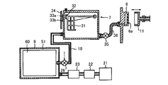
図2は、図1に示した記録装置に搭載されたインク供給システムの構成を模式的に示し
ている。このインク供給システムについて、それぞれ対応する各部を同一符号で示した図
1及び図2を用いて説明する。図1及び図2において、空気加圧ポンプ21により加圧さ
れた空気は、圧力調整弁22に供給される。さらに、この加圧空気は、圧力検出器23を
介して各メインタンク9a〜9d(図2においては代表して符号9として示す)にそれぞ
れ供給される。なお、圧力調整弁22は、空気加圧ポンプ21によって加圧された空気圧
が所定以上に達した時に、圧力を開放して各メインタンク9a〜9dに加わる空気圧を所
定の範囲に維持させる。
FIG. 2 schematically shows the configuration of the ink supply system mounted on the recording apparatus shown in FIG. The ink supply system will be described with reference to FIGS. 1 and 2 in which corresponding parts are denoted by the same reference numerals. 1 and 2, the air pressurized by the
さらに、圧力検出器23は、空気加圧ポンプ21によって加圧された空気圧を検知し、
空気加圧ポンプ21の駆動を制御するように機能する。すなわち、空気加圧ポンプ21に
よって加圧された空気圧が所定の圧力に達したことを検出した場合には、空気加圧ポンプ
21の駆動を停止させると。また、圧力検出器23によって空気圧が定められた圧力以下
となったことを検出した場合には、空気加圧ポンプ21を駆動させるように制御する。し
たがって、この繰り返しによって各メインタンク9a〜9dに加わる空気圧は所定の範囲
に維持されるようになされる。
Furthermore, the
It functions to control the driving of the
メインタンク9としてのインクカートリッジの詳細な構成については後述するが、その
概略構成は図2に示されたように、その外郭を構成するケースは気密にシールされている
。メインタンク9の内部にはインクを封入した可撓性素材により形成されたインクパック
60が収納されている。そして、メインタンク9とインクパック60とで形成される空間
が加圧室51を構成しており、この加圧室51内に、圧力検出器23を介した加圧空気が
供給される。この構成により、各メインタンク9a〜9dに収納された各インクパック6
0は、それぞれ加圧空気による加圧を受け、各メインタンク9a〜9dから各サブタンク
7a〜7dに対して所定の圧力によるインク流が発生するように成される。
The detailed configuration of the ink cartridge as the
0 is respectively pressurized by pressurized air so that an ink flow with a predetermined pressure is generated from the
なお、各メインタンク9a〜9dにおいて加圧されたインクは、キャリッジ1に搭載さ
れた各サブタンク7a〜7d(図2においては代表して符号7とする)に供給される。そ
れらの間は、各インク補給バルブ26,26……および各インク補給チューブ10,10
,……で接続されている。
The ink pressurized in the
, ... are connected.
図2に示すように、サブタンク7には内部にフロート部材31が配置されており、その
フロート部材31の一部には永久磁石32が取り付けられている。そしてホール素子に代
表される磁電変換素子33a,33bが基板34に装着されて、サブタンク7の側壁に添
接されている。この構成により、フロート部材31に配置された永久磁石32と、フロー
ト部材の浮上位置にしたがった永久磁石32による磁力線量に応じて、ホール素子33a
,33bにより電気的出力が発生されるインク量検出手段を構成している。なお、メイン
タンク9に残量検出装置が具備されている場合等では、サブタンク7を省略することがで
きる。
As shown in FIG. 2, a
, 33b constitutes an ink amount detecting means for generating an electrical output. Note that the
各サブタンク7または各メインタンク9からは、バルブ35およびチューブ36を介し
て記録ヘッド6に対してインクが供給される。記録ヘッド6に供給される印刷データに基
づいて、記録ヘッド6のノズル形成面に形成されたノズル開口6aより、インク滴が吐出
される。なお、図2に示すキャッピング手段11に接続されたチューブは、図示せぬ吸引
ポンプ(チューブポンプ)に接続される。
Ink is supplied from each
(インクカートリッジの概要)
図3は、本発明に係る流体収容用であるメインタンク9の概観斜視図である。メインタ
ンク9は、蓋体である上ケース41と筐体である下ケース42とを外殻として有する。メ
インタンク9の前面には、例えば上ケース41に設けられたインク導出口43と、例えば
下ケース42に設けられた加圧空気導入口44が設けられている。
(Outline of ink cartridge)
FIG. 3 is a schematic perspective view of the
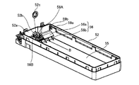
図4は、上ケース41を除いたメインタンク9の分解斜視図であり、図5は、上ケース
41及び封止フィルム70を除いたメインタンク9の平面図である。下ケース42は、周
囲壁52で囲まれた凹所51に、流体収容袋体であるインクパック60が収容される。周
囲壁52の前面側は隔壁52aとされ、隔壁52aの外側には、図5に示す残量検出装置
53が収容される。さらに、インクパック60の前縁側と後縁側の上方空間にスペーサ部
材70,70が配置される。その後、下ケース42の開口端は封止フィルム54により封
止されて、凹所51が加圧室として密閉される。
4 is an exploded perspective view of the
次に、下ケース42に対するインクパック60及びスペーサ部材70,70の取り付け
方法について説明する。図6に示すように、インクパック60の取り付け前に、隔壁52
aに形成された孔52bに、環状の弾性体にて形成されたシール部材52cが配置される
。このシール部材52cは、例えばゴムパッキンにて形成され、孔52bを気密にシール
して、封止フィルム54で封止された凹所(加圧室)51からのエア漏れを防止するもの
である。
Next, a method for attaching the
A
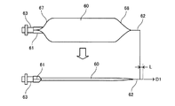
本実施形態に用いられるインクパック60は、主として大容量容器に用いられるガゼッ
トタイプと呼ばれるものである。このインクパック60には、図7に示すように、インク
パック60の前縁側の第1辺に第1の封止接合部61が、この第1辺と対向する後縁側の
第2辺に第2の封止接合部62が、それぞれ形成されている。第1の封止接合部61には
、インク導出部材63が挟持されている。
The
インク導出部材63は、基端64がインクパック60と第1の封止接合部61を介して
連結され、先端側に設けられた導出端部65と基端64との間にフランジ部66が形成さ
れている。このインク導出部材63は弁機構を内蔵している。隔壁52aの外側から残量
検出装置53(図5)がセットされると、残量検出装置53に設けられた接続針(図示せ
ず)が、インク導出部材63に挿入される。この接続針がインク導出部材63内の弁機構
を作動させることで、インクパック60内のインクが導出可能となる。なお、インク残量
検出装置53はインクパック60のインク導出部材63に挿入される接続針の他、接続針
から導出された流体を排出する流体排出部材(図示せず)を含み、接続針とインク排出部
材との間でインクの残量を検出する。また、インク残量検出装置53にも設けられるイン
ク排出部材は、インク導出部材63と実質的に同一原理によってインクの排出が可能であ
る。
The ink lead-
なお、インクパック60は、矩形状に形成された2枚(第1の封止接合部)または3枚
(第2の封止接合部)の可撓性素材、例えばポリエチレンフィルムを熱溶着して形成され
、ガスバリア性の向上のために、例えばアルミ泊等が表面にラミネートされている。
The
インクパック60は、先ず、第1辺にインク導出部材63が介在された状態で例えば熱
溶着によって第1辺が封止されて第1の封止接合部61が形成され、袋形状に形成される
。その後、開封状態にある第2辺からインクが収容される。最後に、第2辺が例えば熱溶
着によって接合されて第2の封止接合部62が形成され、インクパック60が完成する。
First, the
図8は、図7に示す第2の封止接合部62の断面を模式的に示している。第2の封止接
合部62は、第1,第2の可撓性素材62a,62bと、第1,第2の可撓性素材62a
,62bの間にて、折り曲げ線62dにて折り曲げられた第3の可撓性素材62cと、の
3枚の可撓性素材を有する。そして、第3の可撓性素材62cの折り曲げ線62d上にて
第1〜第3の可撓性素材62a〜62cが封止接合される。また、第1,第3の可撓性素
材62a,62cの対向面同士と、第2,第3の可撓性素材62b,62cの対向面同士
とがそれぞれ封止接合されて、第2の封止接合部62形成される。3枚の可撓性素材62
a〜62cが合流する折り曲げ線62d上での接合力は弱いが、この接合力の弱い部分は
、接合力の強い2枚の可撓性素材の接合領域の内側に位置するので、シール性は十分に確
保される。
FIG. 8 schematically shows a cross section of the second sealing joint 62 shown in FIG. The second sealing joint 62 includes first and second
, 62b, and a third
Although the joining force on the
また、本実施形態では、第2の封止接合部62のうち図7にて破線で示す両隅部62e
,62fが、切断位置62g,62hにて切断されている。これにより、コーナー部に生
ずるバリを除去すると共に、隅部62e,62fが面取りされているため、後述するよう
に第2の封止接合部62の移動先端の移動抵抗を少なくできる。
Further, in the present embodiment, both
62f are cut at cutting
なお、本発明に係る流体収容容器には、図7のガゼットタイプのインクパック60に限
らず、矩形状の2枚の可撓性素材の4辺を封止接合したピロータイプを用いることもでき
る。この場合、封止接合部としては、インク導出部材63が連結される第1辺の第1の封
止接合部の他、第1辺に直交する二辺及びは第1辺と対向する辺の計三辺にも封止接合部
が設けられる。
The fluid container according to the present invention is not limited to the gusset-
図7や、図5のA−A線断面図である図9に示すように、インクが充填されたインクパ
ック60は、第1,第2の接合封止部61,62からインクパック60の中心に向かうに
従い厚さが変化する厚さ変化領域67,68を有する。つまり、インクパック60は前縁
側と後縁にて、それぞれ厚さが変化している。下ケース42の開口端を封止する封止フィ
ルム54を介して上ケース41を下ケース42に取り付けても、厚さ変化領域67,68
には空間が形成されてしまう。これを放置すると、搬送時に衝撃によってインクパック6
0を破損させる他、加圧される体積も大きくなる。
As shown in FIG. 7 and FIG. 9 which is a cross-sectional view taken along the line AA in FIG. 5, the
A space will be formed in. If this is left unattended, the ink pack 6 will be shocked during transportation.
In addition to damaging 0, the pressurized volume also increases.
そこで、図6、図9、または下ケース42の平面図である図10に示すように、下ケー
ス42の周囲壁52の内側には、底面55より立ち上がるスペーサ用突起部56,57が
設けられている。下ケース42の前縁側のスペーサ用突起部56は、インクパック60の
前縁側の厚さ変化領域67の下側部分を支持するものである。このスペーサ用突起部56
は、底壁55より隆起した隆起部56aとリブ56bとで構成している。隆起部56a及
びリブ56bの上面は同一角度にて傾斜している。一方、下ケース42の後縁側のスペー
サ用突起部57は、インクパック60の後縁側の厚さ変化領域68の下側部分を支持する
もので、底壁55より隆起した隆起部にて構成されている。
Therefore, as shown in FIG. 6, FIG. 9, or FIG. 10, which is a plan view of the
Is composed of a raised
(規制部材を用いたインクパックの取り付け方法)
以上の構成を有する下ケース42にインクパック60を取り付ける方法について説明す
る。
(How to install an ink pack using a regulating member)
A method of attaching the
図6に示した通り、下ケース42の隔壁52aに形成された孔52bには、環状のシー
ル部材52cが配置されている。インクパック60は、下ケース42の内側より図6に示
す第1の方向Bに向けて、インク導出部材63の導出端部65がシール部材52cに嵌合
するように挿入される。
As shown in FIG. 6, an
ここで、下ケース42には、図6、図10、図11または図9のC部拡大図である図1
2に示すように、底壁55より垂直上方に延びる少なくとも一つ例えば2つの固定リブ5
8A,58Bが形成されている。
Here, the
2, at least one, for example, two fixing
8A and 58B are formed.
この2つの固定リブ58A,58Bの間隔が第1の方向B(図6)の下流に向かうに従
い狭くなるように、2つの固定リブ58A,58Bの横断面が「ハの字」になるように形
成されている。この2つの固定リブ58A,58Bは、インク導出部材63の導出端部6
5を第1の方向Bに移動させてシール部材52cに挿入される際に、フランジ部66によ
り弾性変形して第1の方向Bと交差する方向に押し広げられる。そして、インク導出部材
63がシール部材52cにシールされる位置に達したときに弾性復帰して、フランジ部6
5の挿入後端(基端64側の面)と対向する。つまり、2つの固定リブ58A,58Bは
、インク導出部材63のフランジ部65の挿入後端と対向して、インク導出部材63の抜
け止めストッパとして機能する。
The cross-section of the two fixing
When 5 is moved in the first direction B and inserted into the
5 is opposed to the rear end of insertion (surface on the
一つの課題は、2つの固定リブ58A,58Bが弾性変形するほど薄肉であることから
、衝撃に耐えられるほどのストッパ機能を併せ持たせることが困難なことである。特に、
本実施形態のように容量が大きいインクパック60が使用されるときには、インクカート
リッジ9の落下時には2つの固定リブ58A,58Bに過大な荷重が作用する。
One problem is that since the two fixing
When the
そこで、本実施形態では、2つの固定リブ58A,58Bが、第1の方向Bとは逆方向
の第2の方向E(図12参照)に移動することを規制する規制部材を設けている。この規
制部材は、下ケース42と一体で射出成形して形成することも可能である。固定リブ58
A,58Bの後端にわずかな距離を隔てて剛体を設置できるからである。固定リブ58A
,58Bの後端にわずかな距離を隔てて突出形成する規制部材を下ケース42に一体で形
成するには、固定リブ58A,58Bと規制部材との間に溝が必要である。一方、その溝
を形成するには、金型には逆に薄板状の突出部が必要である。ただし、その突出部を金型
の研削により実現できない場合には、金型に突出部を形成するための薄板を埋め込み固定
することになる。こうすると、金型が複雑化する。
Therefore, in the present embodiment, a restricting member that restricts the movement of the two fixing
This is because a rigid body can be installed at a slight distance from the rear ends of A and 58B.
, 58B, a groove is required between the fixing
そこで、本実施形態では、インクパック60の装着後に、固定リブ58A,58Bの後
端にわずかな距離を隔てて配置される規制部材を、下ケース42とは別部材で形成した設
置することにした。そして、この規制部材の機能を、スペーサ部材70が併せ持つように
した。
Therefore, in the present embodiment, after the
図13(A)〜図13(F)はそれぞれ、スペーサ部材70の正面図、平面図、左側面
図、右側面図、背面図及び底面図である。スペーサ部材70は、例えば合成樹脂にて射出
成形された剛体として形成される。この点、特許文献1のスペーサ部材(押さえ部材)が
発泡スチロールなどの弾性素材で形成されているものとは異なる。
13A to 13F are a front view, a plan view, a left side view, a right side view, a rear view, and a bottom view of the
図13(A)〜図13(F)に示すように、スペーサ部材70の前面71には、規制部
材として機能する2本の規制リブ72,72が突出形成されている。
As shown in FIGS. 13 (A) to 13 (F), on the
このスペーサ部材70は、前面71と、上面73と、各面71,73を結ぶ傾斜面74
とを有する横断面の輪郭が略三角形を呈している。上面73は射出成形時の肉厚をほぼ一
定とするために肉抜きされている。傾斜面74は、図9に示すように、インクパック60
の厚さ変化領域67,68の傾斜面にほぼ相応している。
The
The outline of the cross section having The
The
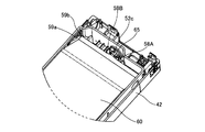
また、スペーサ部材70は、下ケース42に位置決め固定される。このために、スペー
サ部材70の両側面にはそれぞれ、ガイドリブ76,77と被係止部78とが突出形成さ
れている。被係止部78は、図13(E)に示すように、水平面78aと、水平面78a
鉛直下方に向かうに従い厚さが漸減する斜面78bとを有する。一方、下ケース42の周
囲壁52には、図4、図6、図11等に示すように、内壁からの突出高さが鉛直下方に向
かうに従い漸増する係止部59aが設けられている。
The
And an
図14に示すように、スペーサ部材70が矢印方向の鉛直下方に向けて押し下げられる
と、斜面78bが係止部59aと当接して、下ケース42の係止部59aを弾性変形させ
て押し広げる。最終的には、図14の実線で示すように、係止部59aの下方に被係止部
78が入り込み、係止部59aが上方への抜け止めストッパとして機能する。
As shown in FIG. 14, when the
下ケース42の周囲壁52には、図4、図6、図11等に示すように、係止部59の長
手方向の一端に溝59bが形成されており、この溝59bに沿ってスペーサ部材70のガ
イドリブ76が案内される。他のガイドリブ77は、係止部59aの長手方向の他端と当
接して案内される。このガイドリブ76,77と係止部59a及び溝59bとで、スペー
サ部材70の前後方向の位置決めがなされる。
As shown in FIG. 4, FIG. 6, FIG. 11, and the like, a
このように、スペーサ部材70は、下ケース42に対して、少なくともE方向(図12
参照)にて位置決め固定される剛体である。このスペーサ部材70の前面71に形成した
規制リブ72,72が、図12に示すように固定リブ58A,58Bの後端と接して、あ
るいはわずかな距離を隔てて配置される規制部材として機能する。
Thus, the
This is a rigid body that is positioned and fixed in (see Fig. 1). The regulating
インクパック60と共に下ケース42内に収納されるスペーサ部材70が具備され、こ
のスペーサ部材70の体積によりインクパック60に封入されるインク容量が調整された
構成とされる。よって、例えば多種類のスペーサ部材70を用意し、インクパック60に
封入されるインク容量に応じてスペーサ部材70を選択して下ケース42に収納すること
ができる。このため、インクパック60を下ケース42内において大きな隙間を持たせる
ことなく収納することができる。したがって、搬送時における衝撃によってインクパック
60を破損させることを大幅に低減できる。
A
また、下ケース42の加圧室51内に加圧空気が導入される場合には、スペーサ部材7
0が収納される結果、加圧室51内に導入される加圧空気の量を少なくできる。したがっ
て、例えば記録装置に動作電源を投入した後のスタンバイ状態となる時間に遅れを発生さ
せることが回避でき、スループットを向上させることに寄与できる。
When pressurized air is introduced into the pressurizing
As a result of storing 0, the amount of pressurized air introduced into the
このように、スペーサ部材70自体は、インクパック60の容量に合わせて設計されて
、加圧室51内で生ずる空きスペースを埋める機能、インクパック60を押さえてインク
パック60の移動を防止する機能などを有するが、それに追加して規制部材の機能を併せ
持たせることができる。
As described above, the
なお、下ケース42に位置決め固定されるスペーサ部材70の上面73は、図9及び図
12に示すように、下ケース42の周囲壁52の上端よりも低く位置している。換言すれ
ば、スペーサ部材70は、周囲壁52の上端開口を覆う封止フィルム(図4参照)とは接
触しない。このため、仮に、スペーサ部材70の位置決め固定が完全でなく、衝撃等でス
ペーサ部材70が多少移動したとしても、剛体であるスペーサ部材70により封止フィル
ム54が突き破られることはない。従来、発泡スチロール等の弾性素材で形成されたスペ
ーサ部材を封止フィルム54に溶着固定するものがあったが、封止フィルム54が破断す
る虞が高かった。本実施形態では、スペーサ部材70を剛体としたことから、封止フィル
ム54とは非接触となるように機構上で保障した。
The
(受入部を用いた第2の封止部の変位量の吸収)
図13(A)〜図13(F)に示すスペーサ部材70は、図9に示す下ケース42の前
縁側及び後縁側に共用される共通部品である。後縁側に配置されるスペーサ部材70も同
様にして下ケース42に位置決め固定されるが、規制部材の機能は不要である。
(Absorption of displacement amount of second sealing part using receiving part)
The
後端側に配置されるスペーサ部材70は、インクパック60内のインクが導出されるに
従い変位する第2の封止接合部62を受け入れる受入部80(後述する図16参照)を、
周囲壁52との対向面間に形成する機能を有する。
The
It has the function to form between the opposing surfaces of the surrounding
インクパック60は、図15に模式的に示すように、インク導出前の状態と、全てのイ
ンクが導出された後の空状態とでは、特に長手方向の寸法が変化し、空状態では図15に
示す寸法Lだけ長くなる。ここで、インク導出部材63は下ケース42に保持されている
。従って、空状態のインクパック60は、受入部80が存在しない状態では、直線状の第
2の封止接合部62がその延長線上に沿った方向D1に向けて寸法Lだけ変位することに
なる。上述の受入部80は、第2の封止接合部62の変位寸法Lの長さを受け入れるもの
である。
As schematically shown in FIG. 15, the
この点、従来技術では何らの対策は施されていなかった。特に、4辺が封止された小容
量のインクパックに採用される上述したピロータイプでは、封止部の変位量はごくわずか
であることから、そのような対策は特に必要なかった。事実、例えば特許文献1の図4に
、インク導出部が封止される第1辺の封止接合部と直交する二辺の封止接合部を含む断面
図が記載されているが、その二辺の封止接合部の先端と筐体との間には極わずかの隙間し
か設けられていない。同図のスペーサ部材と筐体内壁との間にも極わずかの隙間があるが
、封止接合部が直角に曲がってこの隙間に入り込む余地はないし、そのように設計された
とは到底いえない。
In this regard, no countermeasures have been taken in the prior art. In particular, in the above-described pillow type employed in a small-capacity ink pack with four sides sealed, such a measure is not particularly necessary because the displacement of the sealing portion is very small. In fact, for example, FIG. 4 of
本実施形態では、図9のD部拡大図である図16に示すようにして受入部80を形成し
、図15に示す変位量Lを受入可能としている。つまり、スペーサ部材70とスペーサ用
突起部57との間の隙間に通された第2の封止接合部62は、案内部81によって直進方
向D1以外であって、この方向D1と交差する方向D2に向けて案内している。
In the present embodiment, the receiving
この方向D2とは、方向D1と交差さえしていれば、直線方向、湾曲方向、所定の交差
角をなす複数の直線を組み合わせた屈曲方向、またはこれらを2種以上組み合わせた複合
方向のいずれでもよい。
As long as the direction D2 intersects the direction D1, the direction D2 may be any of a straight direction, a bending direction, a bending direction combining a plurality of straight lines having a predetermined crossing angle, or a combined direction combining two or more of these. Good.
本実施形態では、案内部81は、図10に示すように、スペーサ用突起部57と周囲壁
52とを結ぶ複数の案内リブ81によって形成されている。
In the present embodiment, as shown in FIG. 10, the
特に本実施形態では、図16に示すように、インクパック60が下ケース42に搭載さ
れた当初の時点から、第2の封止接合部62が案内部81(案内リブ81a)によって屈
曲または湾曲されている。従って、インクパック60からインクが導出されるに伴い第2
の封止接合部62が変位する際に、極めて円滑に、スペーサ部材70と周囲壁52との間
の受入部80に進入することになる。従って、加圧室51内に導入される加圧空気によっ
てインクパック60が押されてインクが導出され、それに伴って第2の封止接合部62が
受入部80に円滑に受け入れられる。
In particular, in the present embodiment, as shown in FIG. 16, the second sealing
When the sealing joint 62 is displaced, it enters the receiving
さらに、図7にて説明した通り、第2の封止接合部62の両端は面取りされており、第
1辺の第1の封止接合部61よりも第2の封止接合部62の端部の幅が狭くなっている。
このため、第2の封止接合部62の移動抵抗を少なくして、円滑な移動を確保できる。特
に、第2の封止接合部62はインク充填後に封止されるため、図7に示す両隅部62e,
62fはバリが発生しやすい。このバリを切断しているので、第2の封止接合部62の移
動抵抗はより低減される。
Furthermore, as described in FIG. 7, both ends of the second sealing
For this reason, the movement resistance of the 2nd
62f tends to generate burrs. Since this burr is cut, the movement resistance of the second sealing joint 62 is further reduced.
こうして、第2の封止接合部62の変位が妨げられずに、インクパック60内のインク
を全て導出することが可能になる。
In this way, all the ink in the
特に、この受入部80を、スペーサ部材70と周囲壁52との間のデッドスペースに配
置したので、下ケース42を今まで通りの大きさのままとしてデッドスペースを利用して
第2の封止接合部62の変位を吸収可能とした。
In particular, since the receiving
図17(A)及び図17(B)は、受入部80や案内部81を設けたことの意義を示す
概略説明図である。図17(A)は、特許文献1の図4及び図8のように、第2の封止接
合部62と周囲壁52との間にわずかな隙間を設けた例である。本実施形態では、インク
パック60の先端側に設けたインク導出部材63は、固定リブ58A,58Bに支持され
ているので、その位置は不変である。図17(A)に示すように、インクパック60が充
満状態であるときに、基準位置例えば固定リブ58Aまたは58Bから第2の封止接合部
62の後端位置P1までの距離をL0とする。図17(B)に示すように、インクパック
60が空状態であるときに、基準位置から第2の封止接合部62の後端位置P2までの距
離をL1とする。図17(A)に示すように、基準位置から後縁側の周囲壁52までの距
離L2が、L0<L2<L1(第1の不等式)であるなら、第2の封止接合部62の後端
は変位の途中で周囲壁52に衝突してしまい、それ以上は変位が妨げられる。これが従来
技術であり、その後も加圧室51に加圧空気を導入しても、第2の封止接合部62は変位
せずにインクを導出しなければならない。こうなると、第2の封止接合部62の変位なし
にインクパック60を加圧変形させなければならず、第2の封止接合部62の変位規制が
インクパック60の加圧変形の障害となる。
FIG. 17A and FIG. 17B are schematic explanatory views showing the significance of providing the receiving
図17(B)は、変位前の第2の封止接合部62の後端位置P1と周囲壁52との間に
受入部80を設けた例である。この場合は、変位後の第2の封止接合部62の後端位置P
2までの変位が受入部80によって保障されるので、インクパック60の加圧変形を妨げ
ない。
FIG. 17B is an example in which a receiving
Since the displacement up to 2 is ensured by the receiving
ただし、図17(B)では、図15に示す寸法Lだけ、下ケース42の縦寸法を長くし
なければならない。そこで、上述した案内部81が、第2の封止接合部62を方向D1と
交差する方向D2に屈曲又は湾曲させて案内することで、例えば図17(A)に示す位置
に周囲壁52を設けることを許容でき、それにより下ケース42の長大化の問題は解決し
た。
However, in FIG. 17B, the vertical dimension of the
図17(A)及び図17(B)については、次のように定義することもできる。図17
(A)に示すように、インクパック60内の流体が導出される前のインクパック60にて
、第2の封止接合部62の端部が位置する基準位置P1から、方向D1の先にある前記筐
体の壁部までの距離をS0とする。S0=L2−L0である。また、図17(B)に示す
ように、インクパック60内の流体の全てが実質的に導出された後のインクパック60に
て、基準位置P1から方向D2に沿って移動する移動長さをS1(S1=L1−L0)と
する。なお、図17(B)は方向D1に変位した図であるが、図16に示すように方向D
2への移動長さS1と等しいことは明らかである。以上に定義したS0,S1を用いると
、案内部81を設けることで、S0<S1(第2の不等式)を充足できる。つまり、基準
位置P1から対向壁までの距離S0よりも長い移動長さS2だけ、第2の封止接合部62
の移動を許容できる。
17A and 17B can be defined as follows. FIG.
As shown to (A), in the
It is clear that the moving length to 2 is equal to S1. If S0 and S1 defined above are used, S0 <S1 (second inequality) can be satisfied by providing the
Can be moved.
なお、第1及び第2の不等式は、上述したピロータイプのインクパックにおいて、イン
ク導出部材63が配置される第1辺と対向する第2辺の封止接合部に対して受入部を設け
た例についても当てはまる。
In the first and second inequalities, in the pillow type ink pack described above, a receiving portion is provided for the sealing joint portion on the second side facing the first side where the ink lead-
第2の不等式は、上述したピロータイプのインクパックにおいて、インク導出部材63
が配置される第1辺と直交する2つの第2辺の封止接合部に対して受入部を設けた例につ
いても当てはまる。この第2辺については、インク導出部材63の保持位置が基準位置と
はならないので、第1の不等式は成立しないが、第2の封止接合部62の端部を基準位置
とした第2の不等式は成立する。
The second inequality is the
This also applies to an example in which a receiving part is provided for the sealing joints on the two second sides orthogonal to the first side where the is disposed. For the second side, since the holding position of the ink lead-
(規制部材の変形例)
図18は、図12に示す規制部材72とは異なる規制部材を示している。図18では、
インク導出部材63の導出端部64が、第1方向Bに移動されてシール部材52cに嵌合
挿入された後に、フランジ部66が第1方向Bとは逆方向の第2方向Eに移動することを
規制する規制部材72aを示している。
(Modification example of restriction member)
FIG. 18 shows a restricting member different from the restricting
After the lead-out
この規制部材72aは、スペーサ部材70aの前面71より突出形成されている。なお
、図18に示すスペーサ部材70aは、図13(A)〜図13(F)に示すスペーサ部材
70と比較して、規制部材72に代えて規制部材72aを有する点のみが異なっている。
従って、このスペーサ部材70aもまた、インクパック60の装着後に下ケース42に位
置決め固定されている。
The restricting
Accordingly, the
規制部材72aは、上述した実施形態のように固定リブ58A,58Bの後端に位置す
るのではなく、フランジ部66の後端と対向して配置される。
The restricting
このようにしても、例えばインクパック9を落下させた際にインクパック60が第2の
方向Eに移動しようとすると、フランジ部66の第2の方向Eへの移動を規制部材72a
が防止する。よって、固定リブ58A,58Bには衝撃力が作用しないか、あるいは衝撃
力が低減される。このため、固定リブ58A,58Bの破損が防止される。
Even in this case, for example, when the
Prevent. Therefore, no impact force acts on the fixing
なお、図18に示す実施形態では、固定リブ58A,58Bは必ずしも必要でない。規
制部材72aによってフランジ部66を固定リブ58A,58Bに代わって位置決めでき
るからである。これにより、シール部材52cとフランジ部66との気密シール性を確保
することができる。ただし、固定リブ58A,58Bが存在すると、スペーサ部材70a
を装着する以前に、シール部材52cとフランジ部66との気密シール性を確保すること
ができる。この意味で、固定リブ58A,58Bを設けたほうが好ましい。
In the embodiment shown in FIG. 18, the fixing
Before mounting, the hermetic sealing between the
また、規制部材を下ケース42とは別部材で形成する場合であっても、規制部材をスペ
ーサ部材70,70aに設けるものに限らない。要は、下ケース42に対して少なくとも
第2の方向Eにて位置決め固定されて、インク導出部材63のフランジ部66か、あるい
はそのフランジ部66のストッパ機能を果たす固定リブ58A,58Bの第2の方向Eへ
の移動を規制するものであれば良い。
Further, even when the restricting member is formed of a member different from the
(変形例)
なお、上記のように本実施形態について詳細に説明したが、本発明の新規事項および効
果から実体的に逸脱しない多くの変形が可能であることは当業者には容易に理解できるも
のである。従って、このような変形例はすべて本発明の範囲に含まれるものとする。例え
ば、明細書又は図面において、少なくとも一度、より広義または同義な異なる用語と共に
記載された用語は、明細書又は図面のいかなる箇所においても、その異なる用語に置き換
えることができる。
(Modification)
Although the present embodiment has been described in detail as described above, those skilled in the art can easily understand that many modifications can be made without departing from the novel matters and effects of the present invention. Accordingly, all such modifications are intended to be included in the scope of the present invention. For example, a term described at least once together with a different term having a broader meaning or the same meaning in the specification or the drawings can be replaced with the different term in any part of the specification or the drawings.
本発明に係る流体収容容器の用途は、インクジェット記録装置のインクカートリッジに
限らない。流体噴射ヘッドを備える各種の流体消費装置に流用可能である。
The use of the fluid container according to the present invention is not limited to the ink cartridge of the ink jet recording apparatus. The present invention can be used for various fluid consuming devices including a fluid ejecting head.
また、流体噴射ヘッドを備える流体消費装置の具体例としては、例えば液晶ディスプレ
ー等のカラーフィルタ製造に用いられる色材噴射ヘッドを備えた装置、有機ELディスプ
レー、面発光ディスプレー(FED)等の電極形成に用いられる電極材(導電ペースト)
噴射ヘッドを備えた装置、バイオチップ製造に用いられる生体有機物噴射ヘッドを備えた
装置、精密ピペットとしての試料噴射ヘッドを備えた装置、捺染装置やマイクロデスペン
サ等が挙げられる。
Further, specific examples of the fluid consuming apparatus including the fluid ejecting head include, for example, an apparatus including a color material ejecting head used for manufacturing a color filter such as a liquid crystal display, and an electrode formation such as an organic EL display and a surface emitting display (FED) Electrode material (conductive paste)
Examples include an apparatus equipped with an ejection head, an apparatus equipped with a bio-organic matter ejection head used for biochip production, an apparatus equipped with a sample ejection head as a precision pipette, a printing apparatus, a micro dispenser, and the like.
9 流体収容容器(インクカートリッジ、メインタンク)、41 上ケース、42 筐
体(下ケース)、44 加圧空気導入口、51 加圧室、凹所、52 周囲壁、52a
隔壁、52b 孔、52c シール部材、54 封止フィルム、55 底壁、56,57
スペーサ用突起部、58A,58B 固定リブ、59a,59b スペーサ部材位置決
め固定部、60 流体収容袋体(インクパック)、61 第1の封止接合部、62 第2
の封止接合部、62a〜62c 第1〜第3の可撓性素材、62d 折り曲げ線、63
流体導出部材、64 基端、65 導出端部、66 フランジ部、67,68 厚さ変化
領域、70,70a スペーサ部材、72,72a 規制リブ、76〜78 被位置決め
固定部、80 受入部、81 案内部、81a 案内リブ
9 Fluid container (ink cartridge, main tank), 41 Upper case, 42 Housing (lower case), 44 Pressurized air inlet, 51 Pressurization chamber, recess, 52 Perimeter wall, 52a
Partition, 52b hole, 52c Seal member, 54 Sealing film, 55 Bottom wall, 56, 57
Spacer protrusion, 58A, 58B fixing rib, 59a, 59b Spacer member positioning fixing portion, 60 fluid containing bag (ink pack), 61 first sealing joint, 62 second
Sealing joints, 62a to 62c, first to third flexible materials, 62d fold line, 63
Fluid outlet member, 64 base end, 65 outlet end portion, 66 flange portion, 67, 68 thickness change region, 70, 70a spacer member, 72, 72a regulating rib, 76-78 positioning fixed portion, 80 receiving portion, 81 Guide part, 81a Guide rib
Claims (4)
基端が前記流体収容体の前縁側に連結され、先端側に設けられた導出端部から前記流体収容体に収容された流体を外部に導出するための流体導出部材と、
前記流体導出部材が連結された前記流体収容体を収容する筐体と、を有する流体収容容器であって、
前記筐体の前側の壁部には、孔部が設けられ、
前記孔部には、環状のシール部材が装着され、
前記流体導出部材が連結された流体収容体は、前記流体導出部材の導出端部が前記シール部材に嵌合するように、前記筐体の内部に収容され、
前記流体導出部材の前記導出端部と前記基端との間には、前記導出端部側の第1面と基端側の第2面とを有するフランジ部が設けられており、
前記筐体の内部には、前記流体導出部材を挟むように、前記流体導出部材を支持するための一対のリブが設けられ、
前記一対のリブは、後端部から前端部に向うに従って狭くなるようにハの字状に形成されており、前記流体導出部材を前記リブの後端部から前端部に向かう第1方向に移動させて前記シール部材に嵌合させる際に前記第1方向と交差する方向に押し広げられ、前記流体導出部材が前記シール部材と嵌合する位置に達したときに弾性復帰して前記フランジ部の前記第2面と対向するように構成され、
前記フランジ部は、前記第1面が前記シール部材に対向し、前記第2面が前記リブの前記前端部に対向するように前記筐体内に配置されて、前記シール部材と前記リブの前記前端部とにより挟持され、
前記筐体の内部には、前記リブの後端部側に配置されて、前記リブの前記第1方向とは逆の第2方向への移動を規制する規制部材が設けられることを特徴とする流体収容容器。 A fluid container for containing a fluid;
Proximal end is connected to the front edge of the fluid container, the fluid outlet member for deriving the fluid contained in the fluid container from the outlet end portion provided on the distal end side to the outside,
A fluid container having a housing for housing the fluid container to which the fluid outlet member is coupled ,
A hole is provided in the front wall of the housing ,
An annular seal member is attached to the hole ,
The fluid container to which the fluid lead-out member is coupled is housed in the housing such that the lead-out end portion of the fluid lead-out member is fitted to the seal member,
Between the lead-out end portion and the base end of the fluid lead-out member, a flange portion having a first surface on the lead-out end portion side and a second surface on the base end side is provided,
Inside the housing, a pair of ribs for supporting the fluid outlet member is provided so as to sandwich the fluid outlet member,
The pair of ribs are formed in a square shape so as to become narrower from the rear end portion toward the front end portion, and the fluid outlet member moves in a first direction from the rear end portion of the rib toward the front end portion. When being fitted to the seal member, it is expanded in a direction crossing the first direction, and when the fluid lead-out member reaches a position where it is fitted with the seal member, it is elastically returned to the flange portion. Configured to face the second surface;
Said flange portion, said first surface is opposed to the sealing member, the second surface is disposed in the housing so as to face the front end of the rib, the front end of the said sealing member rib It is sandwiched between the parts,
Inside of the housing, it is arranged on the rear end side of the rib, and the first direction of the ribs and wherein Rukoto provided regulating member for regulating the movement in the second direction opposite to Fluid container.
前記規制部材は、前記筐体とは別の部材により形成され、かつ、前記筐体に対して位置決め支持されていることを特徴とする流体収容容器。 In claim 1,
The regulating member is formed of a member different from the casing, and is positioned and supported with respect to the casing.
前記筐体は、前記前側の壁部と交わる底壁部と前記前側の壁部と対向する後側の壁部とを有し、かつ、前記底壁部と対向する面に開口を有し、
前記筐体の前記開口が封止フィルムによって封止されることで、前記筐体の内部には外部から加圧流体が導入される加圧室が形成され、
前記流体収容体は、前記底壁部と対向する第1面と、前記封止フィルムと対向する第2面と、前記流体導出部材が連結された第1封止部と、前記第1封止部に対向する第2封止部と、を有し、前記第1封止部が前記筐体の前側の壁部側、前記第2封止部が前記筐体の後側の壁部側となるように、前記加圧室内に収容され、
前記流体収容体は、前記第1封止部から前記第2封止部に向かうに従い前記第1面と第2面との間の厚さが変化する厚さ変化領域を有し、
前記流体収容体の前記厚さ変化領域と前記封止フィルムとの間には、剛体であるスペーサ部材が配置され、
前記規制部材は、前記スペーサ部材に一体的に形成されていることを特徴とする流体収容容器。 In claim 2,
The housing has a bottom wall portion that intersects the front wall portion and a rear wall portion that faces the front wall portion, and has an opening on a surface that faces the bottom wall portion,
By sealing the opening of the housing with a sealing film, a pressurized chamber into which a pressurized fluid is introduced from the outside is formed inside the housing.
Wherein the fluid container has a first surface facing the said bottom wall portion, a second surface opposite to the sealing film, a first sealing portion in which the fluid outlet member is connected, the first sealing A second sealing portion facing the portion , wherein the first sealing portion is a front wall portion side of the housing, and the second sealing portion is a rear wall portion side of the housing. Is accommodated in the pressure chamber,
The fluid container has a thickness change region in which a thickness between the first surface and the second surface changes from the first sealing portion toward the second sealing portion,
Between the thickness change region of the fluid container and the sealing film, a spacer member that is a rigid body is disposed,
The fluid storage container, wherein the regulating member is formed integrally with the spacer member .
前記スペーサ部材は、前面と、上面と、前記前面と上面とを結ぶ傾斜面とを有する断面の輪郭が略三角形を呈する部材であり、
前記スペーサ部材は、前記上面が前記封止フィルムと対向し、前記傾斜面が前記流体収容体の前記厚さ変化領域と対向するように、前記加圧室内に配置されており、
前記スペーサ部材の前記上面と、前記封止フィルムとの間に空間部が形成されていることを特徴とする流体収容容器。 In claim 3,
The spacer member is a member that has a front surface, an upper surface, and an outline of a cross section having an inclined surface connecting the front surface and the upper surface, and has a substantially triangular shape.
The spacer member is disposed in the pressurizing chamber so that the upper surface faces the sealing film and the inclined surface faces the thickness change region of the fluid container,
The top surface and the fluid container, wherein a space is formed between the sealing film of the spacer member.
Priority Applications (1)
| Application Number | Priority Date | Filing Date | Title |
|---|---|---|---|
| JP2007072008A JP5125164B2 (en) | 2007-03-20 | 2007-03-20 | Fluid container |
Applications Claiming Priority (1)
| Application Number | Priority Date | Filing Date | Title |
|---|---|---|---|
| JP2007072008A JP5125164B2 (en) | 2007-03-20 | 2007-03-20 | Fluid container |
Publications (3)
| Publication Number | Publication Date |
|---|---|
| JP2008230008A JP2008230008A (en) | 2008-10-02 |
| JP2008230008A5 JP2008230008A5 (en) | 2010-03-18 |
| JP5125164B2 true JP5125164B2 (en) | 2013-01-23 |
Family
ID=39903367
Family Applications (1)
| Application Number | Title | Priority Date | Filing Date |
|---|---|---|---|
| JP2007072008A Expired - Fee Related JP5125164B2 (en) | 2007-03-20 | 2007-03-20 | Fluid container |
Country Status (1)
| Country | Link |
|---|---|
| JP (1) | JP5125164B2 (en) |
Families Citing this family (4)
| Publication number | Priority date | Publication date | Assignee | Title |
|---|---|---|---|---|
| JP6306365B2 (en) * | 2014-02-18 | 2018-04-04 | 理想科学工業株式会社 | ink cartridge |
| JP6379836B2 (en) * | 2014-08-11 | 2018-08-29 | セイコーエプソン株式会社 | Method for manufacturing liquid container and cartridge |
| JP2018122518A (en) | 2017-02-01 | 2018-08-09 | セイコーエプソン株式会社 | cartridge |
| JP7147133B2 (en) * | 2017-06-30 | 2022-10-05 | ブラザー工業株式会社 | liquid containment unit |
Family Cites Families (6)
| Publication number | Priority date | Publication date | Assignee | Title |
|---|---|---|---|---|
| JP4613616B2 (en) * | 2005-01-05 | 2011-01-19 | セイコーエプソン株式会社 | Liquid container module and liquid ejecting apparatus |
| JP4788142B2 (en) * | 2005-01-14 | 2011-10-05 | セイコーエプソン株式会社 | Liquid container and liquid ejecting apparatus |
| JP4561395B2 (en) * | 2005-02-18 | 2010-10-13 | セイコーエプソン株式会社 | Attachment and liquid supply device |
| JP2006312276A (en) * | 2005-05-09 | 2006-11-16 | Konica Minolta Medical & Graphic Inc | Ink cartridge for inkjet recording device, inkjet recording device and ink supply method |
| JP4770369B2 (en) * | 2005-09-29 | 2011-09-14 | ブラザー工業株式会社 | Ink cartridge and frame enclosed in ink cartridge |
| JP4337894B2 (en) * | 2007-03-14 | 2009-09-30 | セイコーエプソン株式会社 | Fluid container |
-
2007
- 2007-03-20 JP JP2007072008A patent/JP5125164B2/en not_active Expired - Fee Related
Also Published As
| Publication number | Publication date |
|---|---|
| JP2008230008A (en) | 2008-10-02 |
Similar Documents
| Publication | Publication Date | Title |
|---|---|---|
| JP4337894B2 (en) | Fluid container | |
| JP4766011B2 (en) | Fluid ejecting apparatus and manufacturing method thereof | |
| US8998394B2 (en) | Ink cartridge, and ink-jet recording apparatus using the same | |
| US6848775B2 (en) | Ink cartridge for recording apparatus | |
| JP4766194B2 (en) | Fluid ejecting apparatus and manufacturing method thereof | |
| US20110057997A1 (en) | Liquid container, methods of assembling or disassembling liquid container, and image forming apparatus | |
| JP5176967B2 (en) | Ink cartridge and image forming apparatus | |
| JP5125164B2 (en) | Fluid container | |
| JP3901626B2 (en) | Ink cartridge and ink jet recording apparatus using the same | |
| JP2002001979A (en) | Ink cartridge for recorder | |
| JP4161846B2 (en) | Liquid container | |
| JP4952655B2 (en) | Fluid ejecting apparatus and manufacturing method thereof | |
| JP2004268575A (en) | Liquid storage means and liquid injection apparatus | |
| JP4280902B2 (en) | Liquid storage bag, liquid cartridge, liquid ejection device | |
| JP4613983B2 (en) | Liquid storage means and liquid ejecting apparatus | |
| JP2001212973A (en) | Ink cartridge for recording apparatus | |
| JP4589610B2 (en) | Liquid container | |
| JP2002254675A (en) | Ink tank | |
| JP2007253419A (en) | Resin case, liquid storing container and inkjet printer | |
| JP2009023336A (en) | Fluid jetting device and its manufacturing method | |
| JP5086553B2 (en) | Liquid container | |
| JP2001293882A (en) | Ink cartridge for recording device | |
| JP4605178B2 (en) | Liquid container | |
| JP4852562B2 (en) | Liquid container | |
| JP2022027016A (en) | Recording device and liquid storage container |
Legal Events
| Date | Code | Title | Description |
|---|---|---|---|
| A521 | Written amendment |
Free format text: JAPANESE INTERMEDIATE CODE: A523 Effective date: 20100203 |
|
| A621 | Written request for application examination |
Free format text: JAPANESE INTERMEDIATE CODE: A621 Effective date: 20100203 |
|
| A131 | Notification of reasons for refusal |
Free format text: JAPANESE INTERMEDIATE CODE: A131 Effective date: 20110809 |
|
| A521 | Written amendment |
Free format text: JAPANESE INTERMEDIATE CODE: A523 Effective date: 20111011 |
|
| TRDD | Decision of grant or rejection written | ||
| A01 | Written decision to grant a patent or to grant a registration (utility model) |
Free format text: JAPANESE INTERMEDIATE CODE: A01 Effective date: 20121002 |
|
| A01 | Written decision to grant a patent or to grant a registration (utility model) |
Free format text: JAPANESE INTERMEDIATE CODE: A01 |
|
| A61 | First payment of annual fees (during grant procedure) |
Free format text: JAPANESE INTERMEDIATE CODE: A61 Effective date: 20121015 |
|
| R150 | Certificate of patent or registration of utility model |
Free format text: JAPANESE INTERMEDIATE CODE: R150 Ref document number: 5125164 Country of ref document: JP Free format text: JAPANESE INTERMEDIATE CODE: R150 |
|
| FPAY | Renewal fee payment (event date is renewal date of database) |
Free format text: PAYMENT UNTIL: 20151109 Year of fee payment: 3 |
|
| S531 | Written request for registration of change of domicile |
Free format text: JAPANESE INTERMEDIATE CODE: R313531 |
|
| R350 | Written notification of registration of transfer |
Free format text: JAPANESE INTERMEDIATE CODE: R350 |
|
| LAPS | Cancellation because of no payment of annual fees |