JP5120631B2 - Battery pack and power supply system - Google Patents
Battery pack and power supply system Download PDFInfo
- Publication number
- JP5120631B2 JP5120631B2 JP2008104361A JP2008104361A JP5120631B2 JP 5120631 B2 JP5120631 B2 JP 5120631B2 JP 2008104361 A JP2008104361 A JP 2008104361A JP 2008104361 A JP2008104361 A JP 2008104361A JP 5120631 B2 JP5120631 B2 JP 5120631B2
- Authority
- JP
- Japan
- Prior art keywords
- assembled battery
- container
- central portion
- electrode body
- refrigerant passage
- Prior art date
- Legal status (The legal status is an assumption and is not a legal conclusion. Google has not performed a legal analysis and makes no representation as to the accuracy of the status listed.)
- Active
Links
- 125000006850 spacer group Chemical group 0.000 claims description 84
- 239000003507 refrigerant Substances 0.000 claims description 79
- 238000001816 cooling Methods 0.000 claims description 70
- 239000000463 material Substances 0.000 claims description 60
- HBBGRARXTFLTSG-UHFFFAOYSA-N Lithium ion Chemical group [Li+] HBBGRARXTFLTSG-UHFFFAOYSA-N 0.000 claims description 36
- 229910001416 lithium ion Inorganic materials 0.000 claims description 36
- 230000007246 mechanism Effects 0.000 claims description 23
- 238000004804 winding Methods 0.000 claims description 11
- 239000003792 electrolyte Substances 0.000 claims description 7
- 238000001514 detection method Methods 0.000 claims description 5
- 230000008859 change Effects 0.000 claims description 4
- 210000004027 cell Anatomy 0.000 description 87
- 208000028659 discharge Diseases 0.000 description 39
- -1 nickel metal hydride Chemical class 0.000 description 22
- 239000000470 constituent Substances 0.000 description 19
- 229920005989 resin Polymers 0.000 description 18
- 239000011347 resin Substances 0.000 description 18
- 229910052782 aluminium Inorganic materials 0.000 description 17
- XAGFODPZIPBFFR-UHFFFAOYSA-N aluminium Chemical compound [Al] XAGFODPZIPBFFR-UHFFFAOYSA-N 0.000 description 17
- 239000004743 Polypropylene Substances 0.000 description 16
- 229920001155 polypropylene Polymers 0.000 description 16
- 238000009826 distribution Methods 0.000 description 7
- 229910052751 metal Inorganic materials 0.000 description 7
- 239000007774 positive electrode material Substances 0.000 description 7
- 230000000452 restraining effect Effects 0.000 description 7
- 239000002826 coolant Substances 0.000 description 6
- 238000005516 engineering process Methods 0.000 description 5
- 239000011888 foil Substances 0.000 description 5
- 239000002184 metal Substances 0.000 description 5
- 239000007773 negative electrode material Substances 0.000 description 5
- PXHVJJICTQNCMI-UHFFFAOYSA-N nickel Substances [Ni] PXHVJJICTQNCMI-UHFFFAOYSA-N 0.000 description 5
- OKTJSMMVPCPJKN-UHFFFAOYSA-N Carbon Chemical compound [C] OKTJSMMVPCPJKN-UHFFFAOYSA-N 0.000 description 4
- RYGMFSIKBFXOCR-UHFFFAOYSA-N Copper Chemical compound [Cu] RYGMFSIKBFXOCR-UHFFFAOYSA-N 0.000 description 4
- 238000006243 chemical reaction Methods 0.000 description 4
- 229910052744 lithium Inorganic materials 0.000 description 4
- 238000000034 method Methods 0.000 description 4
- 239000000203 mixture Substances 0.000 description 4
- 230000004048 modification Effects 0.000 description 4
- 238000012986 modification Methods 0.000 description 4
- 239000011149 active material Substances 0.000 description 3
- 239000003575 carbonaceous material Substances 0.000 description 3
- 239000002131 composite material Substances 0.000 description 3
- 239000012141 concentrate Substances 0.000 description 3
- 238000007796 conventional method Methods 0.000 description 3
- 239000011889 copper foil Substances 0.000 description 3
- 230000006866 deterioration Effects 0.000 description 3
- 230000000694 effects Effects 0.000 description 3
- 239000008151 electrolyte solution Substances 0.000 description 3
- 238000004519 manufacturing process Methods 0.000 description 3
- 239000007769 metal material Substances 0.000 description 3
- 229910052759 nickel Inorganic materials 0.000 description 3
- 238000003860 storage Methods 0.000 description 3
- 229920002134 Carboxymethyl cellulose Polymers 0.000 description 2
- 229910013870 LiPF 6 Inorganic materials 0.000 description 2
- WHXSMMKQMYFTQS-UHFFFAOYSA-N Lithium Chemical compound [Li] WHXSMMKQMYFTQS-UHFFFAOYSA-N 0.000 description 2
- 239000004698 Polyethylene Substances 0.000 description 2
- 230000004323 axial length Effects 0.000 description 2
- 230000009286 beneficial effect Effects 0.000 description 2
- 239000003990 capacitor Substances 0.000 description 2
- 239000004020 conductor Substances 0.000 description 2
- 238000007599 discharging Methods 0.000 description 2
- 238000001035 drying Methods 0.000 description 2
- 229910002804 graphite Inorganic materials 0.000 description 2
- 239000010439 graphite Substances 0.000 description 2
- RSNHXDVSISOZOB-UHFFFAOYSA-N lithium nickel Chemical compound [Li].[Ni] RSNHXDVSISOZOB-UHFFFAOYSA-N 0.000 description 2
- 229910052987 metal hydride Inorganic materials 0.000 description 2
- 239000012046 mixed solvent Substances 0.000 description 2
- 230000000149 penetrating effect Effects 0.000 description 2
- 229920000573 polyethylene Polymers 0.000 description 2
- 239000000843 powder Substances 0.000 description 2
- 238000012545 processing Methods 0.000 description 2
- 230000005855 radiation Effects 0.000 description 2
- 150000003839 salts Chemical class 0.000 description 2
- 229920003002 synthetic resin Polymers 0.000 description 2
- 239000000057 synthetic resin Substances 0.000 description 2
- 229910052723 transition metal Inorganic materials 0.000 description 2
- XLYOFNOQVPJJNP-UHFFFAOYSA-N water Substances O XLYOFNOQVPJJNP-UHFFFAOYSA-N 0.000 description 2
- OIFBSDVPJOWBCH-UHFFFAOYSA-N Diethyl carbonate Chemical compound CCOC(=O)OCC OIFBSDVPJOWBCH-UHFFFAOYSA-N 0.000 description 1
- KMTRUDSVKNLOMY-UHFFFAOYSA-N Ethylene carbonate Chemical compound O=C1OCCO1 KMTRUDSVKNLOMY-UHFFFAOYSA-N 0.000 description 1
- 229910012851 LiCoO 2 Inorganic materials 0.000 description 1
- 229910015643 LiMn 2 O 4 Inorganic materials 0.000 description 1
- 229910013290 LiNiO 2 Inorganic materials 0.000 description 1
- FDLZQPXZHIFURF-UHFFFAOYSA-N [O-2].[Ti+4].[Li+] Chemical compound [O-2].[Ti+4].[Li+] FDLZQPXZHIFURF-UHFFFAOYSA-N 0.000 description 1
- 239000006230 acetylene black Substances 0.000 description 1
- 230000009471 action Effects 0.000 description 1
- 238000007792 addition Methods 0.000 description 1
- 229910003481 amorphous carbon Inorganic materials 0.000 description 1
- 230000015572 biosynthetic process Effects 0.000 description 1
- 229910052799 carbon Inorganic materials 0.000 description 1
- 239000001768 carboxy methyl cellulose Substances 0.000 description 1
- 235000010948 carboxy methyl cellulose Nutrition 0.000 description 1
- 239000008112 carboxymethyl-cellulose Substances 0.000 description 1
- 230000015556 catabolic process Effects 0.000 description 1
- 229910017052 cobalt Inorganic materials 0.000 description 1
- 239000010941 cobalt Substances 0.000 description 1
- GUTLYIVDDKVIGB-UHFFFAOYSA-N cobalt atom Chemical compound [Co] GUTLYIVDDKVIGB-UHFFFAOYSA-N 0.000 description 1
- 238000002485 combustion reaction Methods 0.000 description 1
- 230000003750 conditioning effect Effects 0.000 description 1
- 229910052802 copper Inorganic materials 0.000 description 1
- 239000010949 copper Substances 0.000 description 1
- 238000006731 degradation reaction Methods 0.000 description 1
- 238000013461 design Methods 0.000 description 1
- 238000010586 diagram Methods 0.000 description 1
- 239000000835 fiber Substances 0.000 description 1
- 239000012530 fluid Substances 0.000 description 1
- 239000000446 fuel Substances 0.000 description 1
- 230000017525 heat dissipation Effects 0.000 description 1
- 230000020169 heat generation Effects 0.000 description 1
- 239000011244 liquid electrolyte Substances 0.000 description 1
- 229910021439 lithium cobalt complex oxide Inorganic materials 0.000 description 1
- 229910021445 lithium manganese complex oxide Inorganic materials 0.000 description 1
- 229910003002 lithium salt Inorganic materials 0.000 description 1
- 159000000002 lithium salts Chemical class 0.000 description 1
- 229910021437 lithium-transition metal oxide Inorganic materials 0.000 description 1
- 239000002905 metal composite material Substances 0.000 description 1
- 239000002923 metal particle Substances 0.000 description 1
- 229910021382 natural graphite Inorganic materials 0.000 description 1
- 239000011255 nonaqueous electrolyte Substances 0.000 description 1
- 229920000098 polyolefin Polymers 0.000 description 1
- 229920005672 polyolefin resin Polymers 0.000 description 1
- 230000002040 relaxant effect Effects 0.000 description 1
- 238000007789 sealing Methods 0.000 description 1
- 239000002904 solvent Substances 0.000 description 1
- 210000000352 storage cell Anatomy 0.000 description 1
- 229920003048 styrene butadiene rubber Polymers 0.000 description 1
Images


Classifications
-
- Y—GENERAL TAGGING OF NEW TECHNOLOGICAL DEVELOPMENTS; GENERAL TAGGING OF CROSS-SECTIONAL TECHNOLOGIES SPANNING OVER SEVERAL SECTIONS OF THE IPC; TECHNICAL SUBJECTS COVERED BY FORMER USPC CROSS-REFERENCE ART COLLECTIONS [XRACs] AND DIGESTS
- Y02—TECHNOLOGIES OR APPLICATIONS FOR MITIGATION OR ADAPTATION AGAINST CLIMATE CHANGE
- Y02E—REDUCTION OF GREENHOUSE GAS [GHG] EMISSIONS, RELATED TO ENERGY GENERATION, TRANSMISSION OR DISTRIBUTION
- Y02E60/00—Enabling technologies; Technologies with a potential or indirect contribution to GHG emissions mitigation
- Y02E60/10—Energy storage using batteries
Description
本発明は、複数の単電池を用いて構築された組電池および該組電池を備える電源システムに関する。 The present invention relates to an assembled battery constructed using a plurality of unit cells and a power supply system including the assembled battery.
正極と負極との間をリチウムイオンが行き来することによって充電および放電するリチウムイオン電池、ニッケル水素電池その他の二次電池あるいはキャパシタ等の蓄電素子を単電池とし、複数の該単電池を用いて構築された組電池は、車両搭載用電源あるいはパソコンや携帯端末等の電源として重要性が高まっている。特に、軽量で高エネルギー密度が得られるリチウムイオン電池を単電池として複数直列に接続した組電池は、車両搭載用高出力電源等として好ましく用いられるものとして期待されている。リチウムイオン電池(単電池)に関する従来技術文献として例えば特許文献1が挙げられる。
ところで、リチウムイオン電池の用途のなかには、ハイレート放電(急速放電)を行う態様で使用されることが想定されるものがある。車両の動力源に用いられる組電池(例えば、動力源として電池と内燃機関等のように作動原理の異なる他の動力源とを併用するハイブリッド車両に搭載される組電池)を構築する単電池としてのリチウムイオン電池は、このような使用態様が想定されるリチウムイオン電池の代表例である。しかし、従来の一般的なリチウムイオン電池は、ローレートでの使用(充放電)に対しては比較的高い耐久性を示すものであっても、ハイレートで使用されると性能劣化(内部抵抗の上昇等)を起こしやすいことが知られていた。組電池を構成する単電池のいずれかにおいてこのような性能劣化が起こると、組電池全体としての性能が大幅に低下することとなり得る。 By the way, some uses of the lithium ion battery are assumed to be used in a mode in which high rate discharge (rapid discharge) is performed. As a single battery for constructing an assembled battery used for a power source of a vehicle (for example, an assembled battery mounted on a hybrid vehicle using a battery and another power source having a different operating principle such as an internal combustion engine as a power source) The lithium ion battery is a typical example of a lithium ion battery in which such a usage mode is assumed. However, even though conventional lithium ion batteries show relatively high durability for use at low rates (charging / discharging), performance degradation (increase in internal resistance) when used at high rates Etc.). When such performance deterioration occurs in any of the single cells constituting the assembled battery, the performance of the assembled battery as a whole may be significantly reduced.
特許文献1には、特定構造の炭素材料に導電材を添加した組成の負極と所定濃度の電解液とを用いることによって充放電サイクル経過による内部抵抗の上昇を抑える技術が記載されている。しかしながら、かかる技術によってもハイレート放電(例えば、車両動力源用のリチウムイオン電池等において求められるレベルの急速放電)を繰り返す充放電パターンに対する耐久性を十分に向上させることはできなかった。
そこで本発明は、ハイレートでの使用に対しても良好な耐久性を示す組電池(典型的には、リチウムイオン電池を単電池として構築された組電池)を提供することを目的とする。本発明の他の目的は、組電池を備える電源システムであって、ハイレートで使用されても該組電池の性能をよりよく維持することのできる電源システムの提供である。 Accordingly, an object of the present invention is to provide an assembled battery (typically, an assembled battery constructed by using a lithium ion battery as a single battery) that exhibits good durability even when used at a high rate. Another object of the present invention is to provide a power supply system including an assembled battery that can better maintain the performance of the assembled battery even when used at a high rate.
本発明者は、電極体の一端および他端に正極端子および負極端子がそれぞれ接続された形態の単電池(例えばリチウムイオン電池)に対してハイレート充放電を行うと、上記正極端子接続側端部および負極端子接続側端部の温度上昇に比べてそれらの中央部の温度上昇が大きいことから、該中央部と前記両端部との間に温度差(温度の偏り)が生じることを見出した。このような温度分布が存在すると、相対的に高温の箇所に電池反応(電流)が集中して当該箇所の劣化が進行しやすくなる結果、単電池全体(ひいては、該単電池を構成要素として含む組電池全体)の性能が通常よりも早く劣化することとなり得る。しかも、電池反応が集中する箇所は発熱量も多くなるため、いったん生じた温度差がますます拡大するという悪循環に陥りがちである。そこで本発明者は、かかる温度差を解消または緩和し得る構成を見出して本発明を完成した。 When the present inventor performs high-rate charge / discharge on a unit cell (for example, a lithium ion battery) in which a positive electrode terminal and a negative electrode terminal are respectively connected to one end and the other end of the electrode body, the positive electrode terminal connection side end portion And since the temperature rise of those center parts was large compared with the temperature rise of the negative electrode terminal connection side edge part, it discovered that a temperature difference (temperature deviation) arises between this center part and the said both ends. When such a temperature distribution exists, the battery reaction (current) concentrates at a relatively high temperature location and the deterioration of the location easily proceeds. As a result, the entire single cell (and thus the single cell is included as a component). The performance of the entire assembled battery) may deteriorate faster than usual. In addition, since the amount of heat generation increases at locations where battery reactions concentrate, the temperature difference once generated tends to fall into a vicious circle. Therefore, the present inventor has found a configuration that can eliminate or alleviate such a temperature difference and has completed the present invention.
本発明により提供される組電池は、充放電可能な複数の単電池(典型的にはリチウムイオン電池)と、該単電池から生じる熱を外部に放散させる冷却機構とを備える。前記単電池は、シート状の電極が重ね合わされた形態の電極体(典型的には、該重ね合わされたシート状電極が長手方向に捲回された形態の捲回電極体)が電解質とともに容器に収容された構成を有する。該電極体の一端および他端には正負の電極端子がそれぞれ接続されている。そして、前記冷却機構は、前記電極体の正極端子接続側端部および負極端子接続側端部(すなわち両端部)に比べて、それらの中央部の冷却効率が高くなるように構成されている。 The assembled battery provided by the present invention includes a plurality of chargeable / dischargeable single cells (typically lithium ion batteries) and a cooling mechanism that dissipates heat generated from the single cells to the outside. In the unit cell, an electrode body in a form in which sheet-like electrodes are superposed (typically, a wound electrode body in a form in which the superposed sheet-like electrodes are wound in the longitudinal direction) is placed in a container together with an electrolyte. It has a housed configuration. Positive and negative electrode terminals are connected to one end and the other end of the electrode body, respectively. And the said cooling mechanism is comprised so that the cooling efficiency of those center parts may become high compared with the positive electrode terminal connection side edge part and negative electrode terminal connection side edge part (namely, both ends) of the said electrode body.
かかる構成の組電池によると、ハイレート使用により単電池の両端部に比べて中央部の温度が大きく上昇しがちであるところ、該中央部を両端部よりも高効率に冷却することによって中央部と両端部との間に温度差が生じる事象を解消または緩和することができる。これにより、単電池内における電池反応の偏りおよびこれに起因する部分的な劣化(例えば内部抵抗の上昇)促進を防止し得る。その結果、組電池全体としてハイレート使用に対する耐久性を向上させることができる。 According to the assembled battery having such a configuration, the temperature of the central part tends to rise greatly compared to both ends of the unit cell due to the high rate use, and the central part is cooled more efficiently than the both ends. It is possible to eliminate or alleviate an event in which a temperature difference occurs between both ends. Thereby, it is possible to prevent the bias of the battery reaction in the unit cell and the promotion of partial deterioration (for example, increase in internal resistance) due to this. As a result, the durability against high rate use can be improved as a whole assembled battery.
なお、本明細書において「単電池」とは、組電池を構成する個々の蓄電素子を指す用語であって、特に限定しない限り種々の組成の電池、キャパシタを包含する。また、「二次電池」とは、繰り返し充電可能な電池一般をいい、リチウムイオン電池、ニッケル水素電池等のいわゆる蓄電池を包含する。リチウムイオン電池を構成する蓄電素子は、ここでいう「単電池」に包含される典型例であり、そのような単電池を複数備えて成るリチウムイオン電池モジュールは、ここで開示される「組電池」の一つの典型例である。ここに開示される技術は、扁平形状の外形を有する単電池(例えばリチウムイオン電池)の所定数を、その扁平面が積み重なる方向(積層方向)に配列し、それらの単電池の電極端子を直列または並列に接続してなる組電池に特に好ましく適用され得る。 In the present specification, the “single cell” is a term indicating individual power storage elements constituting the assembled battery, and includes batteries and capacitors of various compositions unless specifically limited. The “secondary battery” refers to a battery that can be repeatedly charged, and includes so-called storage batteries such as lithium ion batteries and nickel metal hydride batteries. The electric storage element constituting the lithium ion battery is a typical example included in the “unit cell” referred to herein, and the lithium ion battery module including a plurality of such unit cells is disclosed in the “assembled battery” Is a typical example. In the technology disclosed herein, a predetermined number of single cells (for example, lithium ion batteries) having a flat outer shape are arranged in a direction in which the flat surfaces are stacked (stacking direction), and electrode terminals of the single cells are arranged in series. Or it can apply especially preferably to the assembled battery formed by connecting in parallel.
ここに開示される技術の好ましい適用対象として、前記単電池が扁平な角型形状の容器を備え、前記電極体(典型的には捲回電極体)は、前記正極端子接続側端部および前記負極端子接続側端部(両端部)がそれぞれ前記容器の横方向の一端部および他端部に位置するようにして該容器内に収容されており、複数の前記単電池が積層方向に配列された構成の組電池が例示される。上記冷却機構は、隣接する前記単電池の扁平面間に形成された冷媒通路(冷媒として機能し得る流体(典型的には空気)を流通させ得る通路)を含む。該冷媒通路は、典型的には、隣接する単電池のうち少なくとも一方の扁平面に面して(上記冷媒通路の少なくとも一部が上記扁平面により区画されるように)形成されている。 As a preferable application object of the technology disclosed herein, the unit cell includes a flat rectangular container, and the electrode body (typically a wound electrode body) includes the positive terminal connecting side end and the electrode body. Negative electrode terminal connection side ends (both ends) are accommodated in the container so as to be positioned at one end and the other end in the lateral direction of the container, respectively, and the plurality of unit cells are arranged in the stacking direction. An assembled battery having the above configuration is exemplified. The cooling mechanism includes a refrigerant passage (a passage through which a fluid (typically air) that can function as a refrigerant can be circulated) formed between the flat surfaces of the adjacent unit cells. The refrigerant passage is typically formed so as to face at least one flat surface of adjacent unit cells (so that at least a part of the refrigerant passage is partitioned by the flat surface).
このような構成を有する組電池の好ましい一態様では、該組電池が、前記積層方向の配列において隣接する前記単電池の扁平面間に配置されたスペーサプレートを備える。該冷媒通路は前記プレートに面して(典型的には、該プレートを挟む少なくとも一方の単電池の扁平面と前記プレートとの間に)形成されている。そして、前記スペーサプレートは、前記横方向の両端部(一端部および他端部)に比べてそれらの中央部のほうが熱伝導率の高い材料により構成されている。かかる構成によると、上記プレートの中央部に設けられた高熱伝導率部分(すなわち、両端部に比べて冷却効率の高い部分)を介して、単電池の横方向中央部の熱を両端部に比べてより効率よく放散させることができる。これにより、中央部と両端部との間に温度差が生じる事象を解消または緩和することができる。 In a preferable aspect of the assembled battery having such a configuration, the assembled battery includes a spacer plate disposed between flat surfaces of the unit cells adjacent in the arrangement in the stacking direction. The refrigerant passage is formed facing the plate (typically, between the flat surface of at least one unit cell sandwiching the plate and the plate). And as for the said spacer plate, those center parts are comprised with the material with higher heat conductivity compared with the both ends (one end part and other end part) of the said horizontal direction. According to such a configuration, the heat at the central portion in the lateral direction of the unit cell is compared with both end portions through the high thermal conductivity portion provided at the center portion of the plate (that is, the portion with higher cooling efficiency than both end portions). Can be dissipated more efficiently. Thereby, the phenomenon which a temperature difference produces between a center part and both ends can be eliminated or eased.
なお、上記スペーサプレートは、例えば、少なくとも一方の表面に横方向の一端から他端に至るように形成された複数の平行な溝(横溝)を有する構成であり得る。また、少なくとも一方の表面に縦方向の上端から下端(横方向と交差(典型的には直交)する平面方向をいい、鉛直方向に限定されない。)に至るように形成された複数の平行な溝(縦溝)を有する構成のスペーサプレートであり得る。あるいは、一方の表面に上記横溝が形成され、他方の表面に上記縦溝が形成された構成のスペーサプレートであってもよい。 The spacer plate may have, for example, a configuration having a plurality of parallel grooves (lateral grooves) formed on at least one surface so as to extend from one end to the other end in the horizontal direction. Also, a plurality of parallel grooves formed on at least one surface so as to extend from the upper end in the vertical direction to the lower end (a planar direction that intersects (typically orthogonal) the horizontal direction and is not limited to the vertical direction). It may be a spacer plate having a structure having (vertical groove). Or the spacer plate of the structure by which the said horizontal groove was formed in one surface, and the said vertical groove was formed in the other surface may be sufficient.
このように横方向の中央部を両端部よりも熱伝導率の高い材料により構成したスペーサプレートによると、例えば横方向の中央部と両端部とで該プレートの構造(冷媒通路を形成する溝の形状や配置等)自体は概ね同様としても、両端部に比べて中央部の冷却効率を高くすることができる。したがって、より単純な構造のスペーサプレートによって本発明の効果(すなわち、単電池の中央部と両端部との温度差を緩和することによって組電池の耐久性を向上させる効果)を実現し得る。また、横方向の中央部を両端部よりも熱伝導率の高い材料により構成したスペーサプレートにおいて、横方向の両端部に比べて中央部では上記扁平面が前記冷媒通路に露出する面積の割合が高くなるように、中央部と両端部とで該プレートの構造を異ならせてもよい。かかる構造のスペーサプレートによると、両端部に対する中央部の冷却効率をより高くすることができ、これにより中央部と両端部との温度差をよりよく緩和または解消することができる。 In this way, according to the spacer plate in which the central portion in the horizontal direction is made of a material having a higher thermal conductivity than both ends, for example, the structure of the plate (the groove forming the refrigerant passage is formed at the central portion in the horizontal direction and both ends. Although the shape, arrangement, etc.) are generally the same, the cooling efficiency of the central portion can be increased compared to the both end portions. Therefore, the effect of the present invention (that is, the effect of improving the durability of the assembled battery by relaxing the temperature difference between the central portion and both end portions of the unit cell) can be realized by the spacer plate having a simpler structure. Further, in the spacer plate in which the central portion in the horizontal direction is made of a material having higher thermal conductivity than both ends, the ratio of the area where the flat surface is exposed to the refrigerant passage in the central portion compared to the both ends in the horizontal direction is The structure of the plate may be different between the center portion and both end portions so as to be higher. According to the spacer plate having such a structure, the cooling efficiency of the central portion with respect to both end portions can be further increased, and thereby, the temperature difference between the central portion and both end portions can be more relaxed or eliminated.
上記構成を有する組電池の好ましい他の一態様では、前記冷却機構が、前記扁平面の前記横方向の両端部に比べて前記中央部では該扁平面が前記冷媒通路に露出する面積の割合が高くなるように構成されている。かかる構成によると、単電池の横方向の中央部では、上記冷媒通路に露出した扁平面を介して、該単電池内で生じた熱を両端部に比べてより効率よく放散させることができる。これにより、中央部と両端部との間に温度差が生じる事象を解消または緩和することができる。 In another preferable aspect of the assembled battery having the above-described configuration, the cooling mechanism has a ratio of an area where the flat surface is exposed to the refrigerant passage at the central portion as compared with both lateral ends of the flat surface. It is configured to be high. According to such a configuration, heat generated in the unit cell can be dissipated more efficiently than the both end units through the flat surface exposed in the refrigerant passage at the central portion in the lateral direction of the unit cell. Thereby, the phenomenon which a temperature difference produces between a center part and both ends can be eliminated or eased.
上記組電池は、前記単電池の扁平面間に配置されたスペーサプレートを備え、該プレートに面して(典型的には、該プレートを挟む少なくとも一方の単電池の扁平面と前記プレートとの間に)前記冷媒通路が形成された構成であり得る。あるいは、例えば扁平面を構成する容器自体に複数の畝状の凸部が略平行に設けられており、かかる凸部を有する扁平面が隣接する単電池の扁平面に押し付けられることで該凸部の間に両扁平面に面する(すなわち、隣接する単電池の容器外面により区画された)冷媒通路が形成される構成であってもよい。 The assembled battery includes a spacer plate disposed between the flat surfaces of the unit cells, and faces the plate (typically, the flat surface of at least one unit cell sandwiching the plate and the plate). The refrigerant passage may be formed between the refrigerant passages. Alternatively, for example, a plurality of bowl-shaped convex portions are provided substantially parallel to the container itself constituting the flat surface, and the flat surface having such convex portions is pressed against the flat surface of the adjacent unit cell. The refrigerant | coolant channel | path which faced both flat surfaces (namely, divided by the container outer surface of the adjacent single cell) may be formed in between.
ここに開示される組電池であって上記スペーサプレート(横方向の中央部が両端部よりも熱伝導率の高い材料からなるプレートであり得る。)を有するいずれかの組電池は、前記スペーサプレートに、該プレートの横方向の一端から他端に至る冷媒通路を区画する溝であって該横方向の一端から他端に向かって延びる横溝が形成された態様であり得る。好ましい一態様では、前記スペーサプレートの横方向の中央部には、該プレートの縦方向の上端から下端に至る冷媒通路を区画する溝であって前記横溝と交差して延びる縦溝が形成されている。かかる構成によると、上記横溝を介して扁平面の横方向に冷媒を流通させることで単電池の全体を冷却するとともに、該単電池の中央部では更に上記縦溝を介して扁平面の縦方向に冷媒を流通させ得ることから、該中央部を両端部に比べてより高効率に冷却することができる。これにより、中央部と両端部との間に温度差が生じる事象を解消または緩和することができる。 Any of the assembled batteries disclosed herein, which includes the spacer plate (the central part in the lateral direction may be a plate made of a material having a higher thermal conductivity than both ends). In addition, it is possible to form a groove that defines a refrigerant passage extending from one end to the other end in the horizontal direction of the plate and extends from one end to the other end in the horizontal direction. In a preferred embodiment, a longitudinal groove extending across the transverse groove is formed at a central portion in the transverse direction of the spacer plate, the groove defining a refrigerant passage extending from the upper end to the lower end in the longitudinal direction of the plate. Yes. According to this configuration, the whole cell is cooled by circulating the refrigerant in the horizontal direction of the flat surface through the horizontal groove, and further in the vertical direction of the flat surface through the vertical groove in the central portion of the cell. Therefore, the central portion can be cooled more efficiently than both end portions. Thereby, the phenomenon which a temperature difference produces between a center part and both ends can be eliminated or eased.
ここに開示される組電池であって上記スペーサプレート(横方向の中央部が両端部よりも熱伝導率の高い材料からなるプレートであり得る。)を有するいずれかの組電池は、前記スペーサプレートに、該プレートの縦方向の上端から下端に至る前記冷媒通路を区画する溝であって該縦方向の上端から下端に向かって延びる縦溝が、前記容器の横方向の一端部、他端部および中央部の夫々に形成された態様であり得る。好ましい一態様では、前記横方向の両端部に比べて前記中央部では、前記縦溝が、より大きな開口幅および/またはより小さなピッチで形成されている。かかる構成によると、上記縦溝を介して冷媒を流通させることで単電池の両端部および中央部を冷却することができ、且つ両端部に比べて中央部では扁平面の面積当たりにより多くの冷媒を流通させ得ることから、該中央部を両端部に比べてより高効率に冷却することができる。これにより、中央部と両端部との間に温度差が生じる事象を解消または緩和することができる。 Any of the assembled batteries disclosed herein, which includes the spacer plate (the central part in the lateral direction may be a plate made of a material having a higher thermal conductivity than both ends). Further, a groove that divides the refrigerant passage from the upper end to the lower end in the vertical direction of the plate and extends from the upper end to the lower end in the vertical direction has one end portion and the other end portion in the horizontal direction of the container. And an embodiment formed in each of the central portions. In a preferred aspect, the longitudinal grooves are formed with a larger opening width and / or a smaller pitch at the central portion than at both lateral end portions. According to such a configuration, both ends and the center of the unit cell can be cooled by circulating the refrigerant through the vertical groove, and more refrigerant per flat area in the center than the both ends. Therefore, the central portion can be cooled more efficiently than both end portions. Thereby, the phenomenon which a temperature difference produces between a center part and both ends can be eliminated or eased.
前記スペーサプレートの横方向の中央部には、該プレートを厚み方向に貫通する開口部が形成されていてもよい。かかる構成のスペーサプレートによると、上記開口部を利用して中央部の熱を放散させ得ることから、該中央部を両端部に比べてより高効率に冷却することができる。これにより、中央部と両端部との間に温度差が生じる事象を解消または緩和することができる。 An opening that penetrates through the plate in the thickness direction may be formed at a central portion in the lateral direction of the spacer plate. According to the spacer plate having such a configuration, the heat of the central portion can be dissipated using the opening, and therefore the central portion can be cooled more efficiently than both end portions. Thereby, the phenomenon which a temperature difference produces between a center part and both ends can be eliminated or eased.
このように横方向の中央部と両端部とで構造が異なるスペーサプレートは、中央部と両端部とが(典型的には該プレートの全体が)同質の材料により形成されていてもよく、あるいは例えば中央部が両端部に比べて熱伝導率の高い材料により形成されていてもよい。全体が同質の材料により形成されたスペーサプレートは、該プレートの製造が容易であるので好ましい。また、中央部が両端部に比べて熱伝導率の高い材料により形成されたスペーサプレートによると、両端部に対する中央部の冷却効率をより高くすることができ、これにより中央部と両端部との温度差をよりよく緩和または解消することができる。 In this way, the spacer plate having a different structure at the center and both ends in the lateral direction may be formed of the same material at the center and both ends (typically, the entire plate), or For example, the central portion may be formed of a material having a higher thermal conductivity than both ends. A spacer plate formed entirely of the same quality material is preferable because the plate can be easily manufactured. In addition, according to the spacer plate formed of a material having a higher thermal conductivity than the both end portions, the central portion can further increase the cooling efficiency of the center portion with respect to the both end portions. The temperature difference can be alleviated or eliminated better.
ここに開示されるいずれかの組電池は、上述のようにハイレートでの使用に対して良好な耐久性を発揮し得ることから、車両に搭載される組電池(例えば、自動車等の車両のモータ(電動機)用の電源)として好適である。したがって本発明によると、ここに開示されるいずれかの組電池を備えた車両が提供される。 Since any of the assembled batteries disclosed herein can exhibit good durability for use at a high rate as described above, an assembled battery mounted on a vehicle (for example, a motor of a vehicle such as an automobile) (Power source for (motor)) is suitable. Therefore, according to this invention, the vehicle provided with one of the assembled batteries disclosed here is provided.
本発明によると、また、充放電可能な複数の単電池(典型的にはリチウムイオン電池)および該単電池から生じる熱を外部に放散させる冷却機構を備えた組電池と、前記冷却機構の作動を制御する冷却制御手段とを備えた電源システムが提供される。前記単電池は、シート状の電極が重ね合わされた形態の電極体(典型的には、該重ね合わされたシート状電極が長手方向に捲回された形態の捲回電極体)が電解質とともに容器に収容された構成を有する。該電極体の一端および他端には正負の電極端子がそれぞれ接続されている。前記冷却機構は、前記電極体の正極端子接続側端部および負極端子接続側端部(両端部)とそれらの中央部との相対的な冷却効率を変更し得るように構成されている。前記冷却制御手段は、前記組電池の放電電流値を検出する電流値検出手段と、その検出値に応じて前記冷却効率を変更する冷却効率調節手段とを備え、前記検出値が所定値よりも高いときに前記中央部の相対的な冷却効率をより高くするように前記冷却機構の作動を制御し得るように構成されている。 According to the present invention, a plurality of chargeable / dischargeable single cells (typically lithium ion batteries), an assembled battery including a cooling mechanism that dissipates heat generated from the single batteries to the outside, and operation of the cooling mechanism And a cooling control means for controlling the power supply system. In the unit cell, an electrode body in a form in which sheet-like electrodes are superposed (typically, a wound electrode body in a form in which the superposed sheet-like electrodes are wound in the longitudinal direction) is placed in a container together with an electrolyte. It has a housed configuration. Positive and negative electrode terminals are connected to one end and the other end of the electrode body, respectively. The said cooling mechanism is comprised so that the relative cooling efficiency of the positive electrode terminal connection side edge part of the said electrode body and a negative electrode terminal connection side edge part (both ends) and those center parts can be changed. The cooling control means includes current value detection means for detecting a discharge current value of the assembled battery, and cooling efficiency adjustment means for changing the cooling efficiency according to the detected value, and the detected value is lower than a predetermined value. The operation of the cooling mechanism can be controlled to increase the relative cooling efficiency of the central portion when the temperature is high.
かかる構成の電源システムによると、中央部と両端部との温度差が大きくなりやすいハイレート充放電時にはローレート充放電時に比べて前記中央部の相対的な冷却効率(両端部に対する冷却効率)がより高くなるように、中央部と両端部との冷却効率のバランスを変更(調節)することができる。このことによって、ハイレートおよびローレートのいずれの使用条件においても単電池内の温度差を適切に緩和または解消することができる。 According to the power supply system having such a configuration, the relative cooling efficiency of the central portion (cooling efficiency with respect to both ends) is higher during high-rate charge / discharge when the temperature difference between the central portion and both ends tends to be larger than during low-rate charge / discharge. Thus, it is possible to change (adjust) the balance of the cooling efficiency between the central portion and both end portions. As a result, the temperature difference in the unit cell can be moderated or eliminated appropriately under both high rate and low rate use conditions.
ここに開示される電源システムを構成する組電池は、前記単電池が扁平な角型形状の容器を備え、前記電極体(典型的には捲回電極体)は、前記正極端子接続部側端部および前記負極端子接続部側端部(両端部)がそれぞれ前記容器の横方向の一端部および他端部に位置するようにして該容器内に収容されており、複数の前記単電池を積層方向に配列された構成の組電池であり得る。前記冷却機構は、隣接する前記単電池の扁平面間に形成された冷媒通路を包含する。ここで、該冷媒通路は前記容器の横方向の一端部、他端部およびそれらの中央部の夫々に、該容器の縦方向に形成されている。 The battery pack constituting the power supply system disclosed herein includes a flat rectangular container in which the unit cell is flat, and the electrode body (typically a wound electrode body) is connected to the positive terminal connecting portion side end. And the negative electrode terminal connecting portion side end portions (both end portions) are accommodated in the container so as to be positioned at one end portion and the other end portion in the lateral direction of the container, respectively, and a plurality of the unit cells are stacked. It may be an assembled battery having a configuration arranged in a direction. The cooling mechanism includes a refrigerant passage formed between flat surfaces of adjacent unit cells. Here, the refrigerant passage is formed in the longitudinal direction of the container at each of one end and the other end in the lateral direction of the container and the central part thereof.
上記組電池は、前記単電池の扁平面間に配置されたスペーサプレートを備え、該プレートに面して(典型的には、該プレートを挟む少なくとも一方の単電池の扁平面と前記プレートとの間に)前記冷媒通路が形成された構成であり得る。あるいは、例えば扁平面を構成する容器自体に複数の畝状の凸部が略平行に設けられており、かかる凸部を有する扁平面が隣接する単電池の扁平面に押し付けられることで該凸部の間に両扁平面に面する(すなわち、隣接する単電池の容器外面により区画された)冷媒通路が形成される構成であってもよい。 The assembled battery includes a spacer plate disposed between the flat surfaces of the unit cells, and faces the plate (typically, the flat surface of at least one unit cell sandwiching the plate and the plate). The refrigerant passage may be formed between the refrigerant passages. Alternatively, for example, a plurality of bowl-shaped convex portions are provided substantially parallel to the container itself constituting the flat surface, and the flat surface having such convex portions is pressed against the flat surface of the adjacent unit cell. The refrigerant | coolant channel | path which faced both flat surfaces (namely, divided by the container outer surface of the adjacent single cell) may be formed in between.
好ましい一態様では、前記冷却機構が、さらに、前記冷媒通路のうち少なくとも一部の開口を少なくとも部分的に遮蔽し得る遮蔽部材であって、前記冷却制御手段により前記遮蔽のタイミングを制御可能に構成された遮蔽部材を包含する。かかる構成の電源システムによると、上記遮蔽部材が中央部および/または両端部の冷媒通路を遮蔽する程度をローレート時とハイレート時とで異ならせることによって、ハイレート時には中央部の相対的な冷却効率がより高くなるように冷却効率のバランスを変更(調節)することができる。このことによって、ハイレートおよびローレートのいずれの使用条件においても単電池内の温度差を適切に緩和または解消することができる。 In a preferred aspect, the cooling mechanism is a shielding member capable of at least partially shielding at least a part of the refrigerant passage, and the timing of the shielding can be controlled by the cooling control means. Including a shield member. According to the power supply system having such a configuration, the relative cooling efficiency of the central portion is increased at the high rate by changing the degree of the shielding member shielding the refrigerant passage at the central portion and / or both ends between the low rate and the high rate. The balance of cooling efficiency can be changed (adjusted) to be higher. As a result, the temperature difference in the unit cell can be moderated or eliminated appropriately under both high rate and low rate use conditions.
ここに開示されるいずれかの電源システムは、該システムを構成する組電池において上述のようにハイレート使用に対する良好な耐久性を実現し得ることから、車両に搭載される電源システム(例えば、自動車等の車両のモータ(電動機)用の電源システム)として好適である。したがって本発明によると、ここに開示されるいずれかの電源システムを備えた車両が提供される。 Since any of the power supply systems disclosed herein can achieve good durability against high-rate use in the assembled battery constituting the system as described above, a power supply system mounted on a vehicle (for example, an automobile or the like) This is suitable as a power supply system for a motor (electric motor) of the vehicle. Therefore, according to this invention, the vehicle provided with one of the power supply systems disclosed here is provided.
ここに開示される技術の好ましい適用対象として、50A以上(例えば50A〜250A)、さらには100A以上(例えば100A〜200A)のハイレート放電を含む充放電サイクルで使用され得ることが想定されるリチウムイオン電池;理論容量が1Ah以上(さらには3Ah以上)の大容量タイプであって10C以上(例えば10C〜50C)さらには20C以上(例えば20C〜40C)のハイレート放電を含む充放電サイクルで使用されることが想定されるリチウムイオン電池;等を単電池として備える組電池および該組電池を備える電源システムが例示される。 As a preferable application object of the technology disclosed herein, lithium ions that can be used in a charge / discharge cycle including a high-rate discharge of 50 A or more (for example, 50 A to 250 A), or even 100 A or more (for example, 100 A to 200 A). Batteries: Large capacity type with a theoretical capacity of 1 Ah or more (and 3 Ah or more), and used in a charge / discharge cycle including high-rate discharge of 10 C or more (for example, 10 C to 50 C) or 20 C or more (for example, 20 C to 40 C). Examples of the battery pack include a lithium ion battery that is assumed to be a single battery, and a power supply system including the battery pack.
また、ここに開示される技術の好ましい適用対象として、電極体を捲回軸の側方からみたときのサイズが捲回軸方向(図4の横方向)について5cm以上(典型的には5cm〜25cm、例えば7cm〜20cm)であるリチウムイオン電池を単電池として備える組電池および該組電池を備える電源システムが例示される。このように電極体の軸長が比較的長い(大型の)リチウムイオン電池では、軸方向の両端部と中央部とで温度差が大きくなりがちであることから、本発明を適用することが特に有益である。 Moreover, as a preferable application target of the technology disclosed herein, the size when the electrode body is viewed from the side of the winding axis is 5 cm or more in the winding axis direction (lateral direction in FIG. 4) (typically from 5 cm to 5 cm). An assembled battery including a lithium ion battery having a size of 25 cm (for example, 7 cm to 20 cm) as a single battery and a power supply system including the assembled battery are exemplified. Thus, in the lithium ion battery having a relatively long (large) axial length of the electrode body, the temperature difference tends to be large between the axial end portions and the central portion. It is beneficial.
また、ここに開示される技術は、正負の電極シートとセパレータとが扁平に捲回された電極体を備え、該電極体を扁平面の法線方向(捲回軸の横方向)からみたサイズが捲回軸方向について5cm以上(典型的には5cm〜25cm、例えば7cm〜20cm)であり、且つ高さ方向(図3の縦方向)について5cm以上(典型的には5cm〜25cm、例えば7cm〜20cm)であるリチウムイオン電池に好ましく適用され得る。このように電極体の軸長が比較的長く且つ高さの大きい(大型の)リチウムイオン電池では、軸方向の両端部と中央部とで温度差が大きくなりがちであることから、本発明を適用することが特に有益である。 Further, the technology disclosed herein includes an electrode body in which a positive and negative electrode sheet and a separator are wound in a flat shape, and the electrode body is a size as viewed from the normal direction of the flat surface (the lateral direction of the winding axis). Is 5 cm or more (typically 5 cm to 25 cm, eg 7 cm to 20 cm) in the winding axis direction, and 5 cm or more (typically 5 cm to 25 cm, eg 7 cm) in the height direction (longitudinal direction in FIG. 3). It can be preferably applied to a lithium ion battery that is ˜20 cm). As described above, in the lithium ion battery having a relatively long and large axial length of the electrode body, the temperature difference tends to be large between the axial end portions and the central portion. It is particularly beneficial to apply.
以下、図面を参照しながら本発明の好適な実施形態を説明する。以下の図面において、同じ作用を奏する部材・部位には同じ符号を付して説明し、重複する説明は省略または簡略化することがある。 Hereinafter, preferred embodiments of the present invention will be described with reference to the drawings. In the following drawings, members / parts having the same action are described with the same reference numerals, and overlapping descriptions may be omitted or simplified.
なお、本明細書において特に言及している事項以外の事柄であって本発明の実施に必要な事柄(例えば、正極、負極およびセパレータの構成および製法、電極体の製造方法、車両への組電池搭載方法)は、当該分野における従来技術に基づく当業者の設計事項として把握され得る。本発明は、本明細書に開示されている内容と当該分野における技術常識とに基づいて実施することができる。 Note that matters other than matters specifically mentioned in the present specification and necessary for carrying out the present invention (for example, configuration and manufacturing method of positive electrode, negative electrode and separator, manufacturing method of electrode body, assembled battery for vehicle) The mounting method) can be grasped as a design matter of those skilled in the art based on the prior art in the field. The present invention can be carried out based on the contents disclosed in this specification and common technical knowledge in the field.
本発明に係る組電池は、特に自動車等の車両に搭載されるモータ(電動機)用電源として好適に使用し得る。したがって本発明は、図18に模式的に示すように、かかる組電池10を電源として備える車両(典型的には自動車、特にハイブリッド自動車、電気自動車、燃料電池自動車のような電動機を備える自動車)1を提供する。
The assembled battery according to the present invention can be suitably used as a power source for a motor (electric motor) mounted on a vehicle such as an automobile. Accordingly, as schematically shown in FIG. 18, the present invention provides a vehicle (typically, an automobile equipped with an electric motor such as an automobile, particularly a hybrid automobile, an electric automobile, or a fuel cell automobile) having such an assembled
また、本発明に係る電源システムは、特に自動車等の車両に搭載されるモータ(電動機)用の電源システムとして好適に使用し得る。したがって本発明は、かかる電源システムを搭載した車両(例えば図18に模式的に示すように、組電池10を含んで構築された電源システム2を備える自動車)1を提供する。
The power supply system according to the present invention can be suitably used as a power supply system for a motor (electric motor) mounted on a vehicle such as an automobile. Therefore, the present invention provides a vehicle (for example, an automobile including the
<例1>
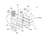
単電池としてリチウムイオン電池を用いる場合を例として、図1〜5を参照しつつ、本実施形態(例1)に係る組電池10の構成を説明する。
<Example 1>
The configuration of the assembled
本実施形態に係る組電池10は、複数の充放電可能な単電池(ここではリチウムイオン電池)20を備える。単電池20は、従来の一般的な組電池に装備される単電池と同様、所定の電池構成材料(正負極それぞれの集電体に正負極それぞれの活物質が保持されたシート状の電極、セパレータ等)を具備する扁平形状の捲回電極体80が、適当な液状電解質(電解液)とともに、該電極体を収容し得る形状(ここでは扁平な直方体形状すなわち角型)の容器50に収容された構成を有する。容器50を構成する材質は、例えば典型的な単電池で使用されるものと同様とすることができ、特に制限はない。単電池20の放熱性等の観点から、金属製(例えばアルミニウム製)の容器50を好ましく使用し得る。容器50の上面には、捲回電極体80の正極および負極とそれぞれ電気的に接続する正極端子60および負極端子62が設けられている。そして、隣接する単電池20間において一方の正極端子60と他方の負極端子62とが接続具64によって電気的に接続されている。このように複数の単電池20を直列に接続することにより、所望する電圧の組電池10が構築されている。
The assembled
図3および図4を参照しつつ、単電池20の構成をより詳しく説明する。
The configuration of the
電極体80は、図4に示すように、通常のリチウムイオン電池の捲回電極体と同様、長尺シート状の正極82(以下「正極シート82」ともいう。)と長尺シート状の負極84(以下「負極シート84」ともいう。)とを計二枚の長尺シート状セパレータ86(以下「セパレータシート86」ともいう。)とともに積層して長手方向に捲回し、次いで得られた捲回体を側面方向(捲回軸に対して横方向)から押しつぶして拉げさせることによって作製され得る。
As shown in FIG. 4, the
ここで、正極シート82と負極シート84とは、これら長尺状シートの幅方向に位置をややずらして重ね合わされた状態で捲回される。その結果として、捲回電極体80の捲回軸方向の一方および他方の端部には、図4に示すように、正極シート82の幅方向の一端が捲回コア部分81(すなわち正極シート82の正極活物質層形成部分と負極シート84の負極活物質層形成部分とセパレータシート86とが密に捲回された部分)から外方にはみ出した正極はみ出し部(正極端子接続部)82Aと、負極シート84の幅方向の一端が捲回コア部分81から外方にはみ出した負極はみ出し部(負極端子接続部)84Aとがそれぞれ形成されている。正極はみ出し部(すなわち正極活物質層の非形成部分)82Aおよび負極はみ出し部(すなわち負極活物質層の非形成部分)84Aには正極リード端子82Bおよび負極リード端子84Bがそれぞれ付設されており、それらのリード端子82B,84Bがそれぞれ上述の正極端子60および負極端子62と電気的に接続される。
Here, the
かかる捲回電極体80を構成する材料および部材自体は、従来のリチウムイオン電池の電極体と同様でよく、特に制限はない。例えば、正極シート82は長尺状の正極集電体の上にリチウムイオン電池用正極活物質層が付与されて形成され得る。正極集電体にはアルミニウム箔(本実施形態)その他の正極に適する金属箔が好適に使用され得る。正極活物質としては従来からリチウムイオン電池に用いられる物質の一種または二種以上を特に限定することなく使用することができる。好適例として、リチウムニッケル系複合酸化物(リチウムとニッケルとを構成金属元素として含む酸化物をいい、ニッケルサイトの一部(典型的には半分以下)がコバルトやアルミニウム等の他の金属元素で置換されたものを包含する意味である。典型的にはLiNiO2)、リチウムコバルト系複合酸化物(典型的にはLiCoO2)、リチウムマンガン系複合酸化物(典型的にはLiMn2O4)等のリチウム遷移金属複合酸化物が挙げられる。例えば、厚さ5μm〜20μm(例えば15μm)程度の長尺状アルミニウム箔を集電体として使用し、その表面の所定領域に常法によりリチウムニッケル系複合酸化物を主体とする正極活物質層を形成することによって好適な正極シート82が得られる。
The material and the member constituting the
一方、負極シート84は長尺状の負極集電体の上にリチウムイオン電池用負極活物質層が付与されて形成され得る。負極集電体には銅箔(本実施形態)その他の負極に適する金属箔が好適に使用され得る。負極活物質としては従来からリチウムイオン電池に用いられる物質の一種または二種以上を特に限定することなく使用することができる。好適例として、グラファイトカーボンやアモルファスカーボン等の炭素系材料、リチウム遷移金属酸化物(リチウムチタン酸化物等)、リチウム遷移金属窒化物等が挙げられる。例えば、厚さ5μm〜20μm(例えば10μm)程度の長尺状銅箔を使用し、その表面の所定領域に常法によって炭素系材料(典型的には黒鉛)を主体とする負極活物質層を形成することによって好適な負極シート84が得られる。
On the other hand, the
また、正負極シート82,84間に使用される好適なセパレータシート86としては、合成樹脂(例えばポリエチレン、ポリプロピレン等のポリオレフィン)により構成されたものが例示される。例えば、ポリオレフィン系樹脂からなる厚さ5μm〜30μm(例えば25μm)程度の多孔質セパレータシートを好適に使用し得る。
Moreover, as a
得られた扁平形状の捲回電極体80を容器50内に、図3に示すように捲回軸が横倒しになるようにして(すなわち、電極体80の正極はみ出し部82A側の部分および負極はみ出し部84A側の部分が容器50の横方向の一端部および他端部にそれぞれ位置するようにして)収容するとともに、適当な非水電解液(図示せず)を注入して封止することによって単電池20が構築される。上記電解液としては、例えば、非水溶媒(ジエチルカーボネートとエチレンカーボネートとの混合溶媒等)中に適当な支持塩(例えばLiPF6等のリチウム塩)を適当量(例えば濃度1M)含むものを好ましく用いることができる。
The obtained flat
本実施形態の組電池10では、図1および図2に示すように、上記構成を有する複数(ここでは4つを図示している。)の単電池20が所定方向に配列され且つ該配列方向に荷重が加えられた状態で拘束されている。具体的には、複数の単電池20は、それぞれの正極端子60および負極端子62が交互に配置されるように一つづつ反転させて配置されており、容器50の側壁をなす扁平面52(容器50の幅広な面、すなわち容器50内に収容される捲回電極体80の扁平面に対応する面)が互いに向かい合う方向(積層方向)に配列される。
In the assembled
配列させた単電池20の周囲には、複数の単電池20をまとめて拘束する拘束部材が配備される。すなわち、単電池配列方向の最外側に位置する単電池20のさらに外側には、一対の拘束板70A,70Bが配置される。また、当該一対の拘束板70A,70Bを架橋するように締付け用ビーム材72が取り付けられる。そして、ビーム材72の端部をビス74により拘束板70Aに締め付け且つ固定することによって、上記単電池20をその配列方向に所定の荷重が加わるように(例えば、扁平面52の受ける面圧が2×10⁶〜5×10⁶Pa程度となるように)拘束することができる。ビーム材72の締め付け具合に応じたレベルで、締め付け方向(すなわち配列方向)への拘束荷重(面圧)が各単電池20の扁平面52に加えられる。
A restraining member that restrains the plurality of
ここで、上記配列された単電池20の間隙の少なくとも一箇所(図示した例では隣接する各単電池20の間および単電池配列方向の両アウトサイド)にはスペーサプレート140が配置される。これにより組電池10の冷却機構としての冷媒通路146が形成される。本実施形態のスペーサプレート140は、図3および図5によく示されるように、全体として容器50の扁平面52とほぼ同じサイズの長方形板状を呈し、その一方の表面は横方向に直線状に延びる畝状の凸部142および溝状の凹部144が交互に形成された凹凸形状(すなわち、図3に示すように側面からみて櫛型の凹凸形状)となっている。特に限定するものではないが、凸部42の幅を例えば0.2cm程度とし、直線状に形成された凹部44の幅を0.8cm程度、凹部44の深さ(すなわち凸部42の高さ)を0.2cm程度とすることができる。一方、プレート140の他方の表面(裏面)はフラットな形状である。
Here, the
かかる形状のプレート140を図2に示すように単電池20とともに拘束すると、図3に示すように、該プレート140の表面側(凹凸形状が形成された側)に隣接する単電池20の扁平面52に凸部142の先端が密接する一方、該凸部142の間に形成された凹部(横溝)144は扁平面52と接触しないことから、隣接する単電池20の扁平面52間に、一方の単電池20の扁平面52およびプレート140(溝144)に面する空隙146が形成される。この空隙146に冷却用媒体(典型的には空気)を流通させる(すなわち、該空隙146を冷媒通路として利用する)ことにより、単電池20で発生する熱を放散させることができる。なお、プレート140の裏面は、他方の単電池20の扁平面52にその全面が密接している。
When the
ここで、図5に示すように、本実施形態のプレート140は、横方向の一端部(正極端子接続側端部)140Aおよび他端部(負極端子接続側端部)140Bと、それらの中央部140Cとに異なる構成材料を用いて形成されている。上記表面の凹凸形状(凸部142および凹部144)は、これら材質の異なる部分に跨って、プレート140の横方向の一端から他端に至るように形成されている。これらの構成材料は、両端部140A,140Bの構成材料に比べて中央部140Cの構成材料の熱伝導率のほうが高くなるような組み合わせで選択される。例えば、両端部140A,140Bの構成材料として樹脂材料(例えば、軽量で硬質なポリプロピレンその他の合成樹脂材料)を、中央部140Cの構成材料として金属材料(例えば、軽量で熱伝導性の高いアルミニウムその他の金属材料)を好ましく採用し得る。また、両端部140A,140Bの構成材料と中央部140Cの構成材料との組み合わせが、熱伝導率の異なる樹脂材料同士または金属材料同士であってもよい。あるいは、例えば両端部140A,140Bの構成材料としてポリプロピレン等の樹脂材料を用い、中央部140Cの構成材料として該樹脂材料と金属との複合材料(例えば、金属粒子、金属繊維等が混入された樹脂材料)を用いてもよい。
Here, as shown in FIG. 5, the
なお、一端部140A、他端部140Bおよび中央部140Cの幅(横方向長さ)は特に限定されず、単電池および組電池の構成、組電池の使用態様、目標とする温度差緩和の程度等を考慮して適宜設定することができる。通常は、製造容易性等の観点から一端部140Aと他端部140Bとを同程度の幅とすることが好ましい。例えば、一端部:中央部:他端部の幅の比率が1:2:1〜2:1:2程度である構成を好ましく採用し得る。本実施形態では上記比率を概ね1:1:1としている。
The widths (lateral lengths) of the one
ここで、熱流速密度(単位時間に単位面積を流れる熱量)Jと熱伝導率λとの間には次式:J=−λ(gradT);で表される関係がある(式中のgradTは温度勾配を示す)。したがって、放熱部材(ここではスペーサプレート140)を構成する材料の熱伝導率λが例えば2倍になると、該部材により放熱される熱量も同じ倍率(ここでは2倍)で増加する。このことを利用して、上記構成のプレート140によると、単電池20のうち両端部140A,140Bに密接する部分(捲回電極体80の軸方向両端部に対応する。)に比べて中央部140Cに密接する部分(電極体80の軸方向中央部に対応する。)では、より熱伝導率の高い材料により構成された中央部140Cを介して、より効率よく放熱を行う(すなわち、中央部140Cに密接する部分をより高効率に冷却する)ことができる。本実施態様では、中央部140Cの構成材料としてアルミニウム(室温付近における熱伝導率236W/m・K程度)、両端部140A,140Bの構成材料としてポリプロピレン樹脂(熱伝導率0.17〜0.19W/m・K程度)を使用する。この組み合わせでは中央部140Cの熱伝導率が両端部140A,Bの1000倍以上である。これにより捲回電極体80の両端部に比べて中央部の冷却効率をより高くすることができる。
Here, there is a relationship represented by the following formula: J = −λ (gradT); between the heat flow density (the amount of heat flowing through the unit area per unit time) J and the thermal conductivity λ (gradT in the formula) Indicates a temperature gradient). Therefore, when the thermal conductivity λ of the material constituting the heat radiating member (here, the spacer plate 140) is doubled, for example, the amount of heat radiated by the member is also increased by the same factor (here, doubled). By utilizing this fact, according to the
上記構成を採用する意義を確認するため、上記実施形態における単電池20と同様の構成を有するリチウムイオン電池を作製し、ハイレート充放電によって両端部と中央部との間に生じる温度差を測定した。
In order to confirm the significance of adopting the above configuration, a lithium ion battery having the same configuration as the
すなわち、ニッケル酸リチウム粉末(正極活物質)とアセチレンブラック(導電材)とカルボキシメチルセルロース(CMC)とを、これら材料の質量比が87:10:3となるようにイオン交換水と混合して活物質組成物(正極活物質組成物)を調製した。正極集電体としては長尺状のアルミニウム箔を使用し、該集電体のうち幅方向の一端を残して(正極はみ出し部82A)それ以外の領域の両面に、上記正極活物質組成物を帯状に塗布して乾燥させた。乾燥後、正極集電体およびその両面に設けられた活物質層を含む全体をプレスして正極シート82を得た。
That is, lithium nickelate powder (positive electrode active material), acetylene black (conductive material), and carboxymethyl cellulose (CMC) are mixed with ion-exchanged water so that the mass ratio of these materials is 87: 10: 3. A material composition (positive electrode active material composition) was prepared. A long aluminum foil is used as the positive electrode current collector, and one end of the current collector is left in the width direction (positive
また、天然黒鉛(粉末)とスチレンブタジエンゴム(SBR)とCMCとを、これら材料の質量比が98:1:1となるようにイオン交換水と混合して活物質組成物(負極活物質組成物)を調製した。負極集電体としては長尺状の銅箔を使用し、該集電体のうち幅方向の一端を残して(負極はみ出し部84A)それ以外の領域の両面に、上記負極活物質組成物を帯状に塗布して乾燥させた。乾燥後、負極集電体およびその両面に設けられた活物質層を含む全体をプレスして負極シート84を得た。
Further, natural graphite (powder), styrene butadiene rubber (SBR), and CMC are mixed with ion-exchanged water so that the mass ratio of these materials becomes 98: 1: 1. Prepared). A long copper foil is used as the negative electrode current collector, and one end in the width direction is left out of the current collector (negative
セパレータシート86としては二枚の多孔質ポリエチレンシートを使用した。これらのセパレータシート86と上記で得られた正極シート32および負極シート34とを、はみ出し部32A,34Aがそれぞれの幅方向の両側からはみ出すように積層して長手方向に捲回し、その捲回体を側方から押しつぶして扁平形状の捲回電極体80を得た。
As the
この電極体80の正極はみ出し部82Aを構成する正極シート82を径方向(扁平面に対する法線方向)に寄せ集めてアルミニウム製の正極リード端子82Bを溶接し、負極はみ出し部84Aを構成する負極シート84を径方向に寄せ集めて銅製の負極リード端子84Bを溶接した。これらのリード端子82B,84Bを容器50の正極端子60および負極端子62にそれぞれ接続した。
The
容器50としては、高さ(縦方向長さ)9.2cm、幅(横方向長さ)11cm、厚さ1.35cmの扁平な箱型の外形を有するアルミニウム容器を使用した。図2に示すように容器50の内部に捲回電極体80を収容した。また、各部の温度を外部から測定可能とするため、リチウムイオン電池20の作製において容器50の一方の端部(正極端子側の端部)、他方の端部(負極端子側の端部)およびそれらの中央部にそれぞれ熱電対をセットした。この容器50に、ECとDMCとEMCとの混合溶媒に支持塩としてのヘキサフルオロリン酸リチウム(LiPF6)を約1mol/リットルの濃度で含有させた電解液を注入した後、該容器50を封止した。その後、常法により初期充放電処理(コンディショニング)を行って、理論容量5Ahのリチウムイオン電池20を得た。
As the
上記で得られたリチウムイオン電池20に対し、150A(放電時間率30Cに相当する。)で10秒間のハイレート放電を含む充放電パターンを付与し、これによる各部の温度変化を上記熱電対による検出値から把握した。より具体的には、室温(約25℃)環境下において以下の(1)〜(4)の充放電パターンを付与し、その前後で各部の温度を比較することにより、上記充放電パターンによる各部の温度上昇幅を求めた。
A charge / discharge pattern including a high rate discharge for 10 seconds at 150 A (corresponding to a discharge time rate of 30 C) is applied to the
[充放電パターン]
(1)150Aで10秒間放電。
[Charge / discharge pattern]
(1) Discharge at 150 A for 10 seconds.
(2)5秒間休止。 (2) Pause for 5 seconds.
(3)40Aで120秒間CC−CV充電(40Aで3.72Vまで定電流充電後、合計充電時間が120秒となるまで定電圧充電)。 (3) CC-CV charge at 40 A for 120 seconds (constant voltage charge until constant charge is 120 seconds after constant current charge to 3.72 V at 40 A).
(4)5秒間休止。 (4) Pause for 5 seconds.
その結果、上記充放電パターン(1サイクル)の前後で、電池の両端部における温度上層幅は1.2℃であったのに対し、中央部の温度上昇幅は2.2℃であった。すなわち、上記のようなハイレート(急速)充放電パターンでは、わずか10秒間のハイレート放電を1回行っただけでも電池の両端部と中央部との間に明確な温度差が生じた。さらに充放電パターンを継続すると、相対的に高温の箇所に電池反応(電流)が集中し、これにより上記高温の箇所においてより多くの熱が発生することにより、いったん生じた温度差がますます拡大することとなる。例えば、上記充放電パターンを連続して繰り返した後における中央部と両端部との温度差は7℃に拡大していた。 As a result, before and after the charge / discharge pattern (one cycle), the temperature upper layer width at both end portions of the battery was 1.2 ° C., whereas the temperature increase width at the center portion was 2.2 ° C. That is, in the high-rate (rapid) charge / discharge pattern as described above, a clear temperature difference was generated between the both ends and the center of the battery even after only one high-rate discharge for 10 seconds. If the charge / discharge pattern continues further, the battery reaction (current) concentrates on the relatively hot spot, and as a result, more heat is generated at the hot spot, increasing the temperature difference once generated. Will be. For example, the temperature difference between the central portion and both end portions after the charge / discharge pattern was continuously repeated was increased to 7 ° C.
ハイレート充放電によって上記のような温度分布を生じる単電池を用いて上記実施形態と同様の組電池10を構築した場合における単電池20の横方向の温度分布イメージを図6に示す。図中の二点鎖線は、該組電池10を構成するスペーサプレートとして、上記実施形態のスペーサプレート140と同様の外形を有し、ただし上記実施形態とは異なり両端部140A,Bのみならず中央部140Cもポリプロピレン樹脂により構成された(すなわち全体が単一の材料からなる)スペーサプレートを用いた場合の温度分布を模式的に示している。このように、電池の横方向の各部における断面形状および熱伝導率(ひいては冷却効率)が同じスペーサプレートによると、単電池20の両端部と中央部との間に温度差が生じる。
FIG. 6 shows a lateral temperature distribution image of the
図6中の一点鎖線は、上記実施形態のスペーサプレート140と同様の外形を有し、ただし上記実施形態とは異なり中央部140Cのみならず両端部140A,Bもアルミニウムにより構成されたスペーサプレートを用いた場合の温度分布を模式的に示している。このように全体がアルミニウム製のプレートによると、全体がポリプロピレン樹脂製のプレートに比べて電池の横方向の各部における冷却効率は上昇するものの、横方向の各部におけるプレートの断面形状および熱伝導率が同じであることに変わりはないことから、依然として単電池20の両端部と中央部との間に温度差が生じる。
The alternate long and short dash line in FIG. 6 has the same external shape as the
これに対して本実施形態のスペーサプレート140では、両端部140A,Bをポリプロピレン樹脂により構成するとともに中央部140Cのみを熱伝導率の高いアルミニウムにより構成することにより、図6に実線で模式的に示すように、全体がポリプロピレン樹脂製のスペーサプレートを用いた場合(二点鎖線)に比べて中央部の温度を集中的に(両端部よりも大きく)低下させることができる(図6中の下向き矢印)。これにより、中央部と両端部との間の温度差を緩和する(温度分布をなだらかにする)ことができる。
On the other hand, in the
<例2>
本実施形態に係る組電池は、上述した例1に係る組電池とはスペーサプレートの外形が異なる一例である。すなわち本実施形態では、図5に示す形状のスペーサプレート140に代えて、図7に示すように、縦方向に直線状に延びて該縦方向の一端(上端)から他端(下端)に至る凸部243および凹部(縦溝)245が交互に平行に形成されたスペーサプレート240を用いる。その他の部分の構成は例1に係る組電池10と同様である。すなわち、本実施形態のプレート240は、例1のスペーサプレート140と同様に、両端部240A,240Bの構成材料(例えばポリプロピレン樹脂)に比べて、中央部240Cはより熱伝導率の高い材料(例えばアルミニウム)により構成されている。
<Example 2>
The assembled battery according to the present embodiment is an example in which the outer shape of the spacer plate is different from the assembled battery according to Example 1 described above. That is, in this embodiment, instead of the
かかる構成のスペーサプレート240を隣接する単電池20間に配置すると、該プレート240の凹部(縦溝)245と該プレート240の表面側に隣接する容器50の扁平面52との間に、縦方向の上端から下端まで延びる冷媒通路247が区画形成される。そして、プレート240の両端部240A,240Bに形成された(容器50の横方向の両端部に面する)冷媒通路247に比べて、中央部240Cに形成された(容器50の横方向の両端部に面する)冷媒通路247によるとより多くの熱を放散させる(すなわち、中央部140Cに密接する部分をより高効率に冷却する)ことができる。これにより両端部と中央部との温度差を緩和または解消することができる。
When the
<例3>
本実施形態に係る組電池は、上述した例1に係る組電池とはスペーサプレートの外形が異なる他の例である。すなわち図8に示すように、本実施形態のスペーサプレート340は、図5に示すスペーサプレート140の横方向の中央部において、隣り合う凹部(横溝)144を隔てる壁面(凸部142)に切れ目341が設けられた構成を有する。このことによって、横溝144と交差して縦方向に延びる一本の縦溝345が形成されている。横溝144と縦溝345とはそれらの交点で連絡している。その他の部分の構成は例1に係る組電池10と同様である。すなわち、本実施形態のプレート340は、例1のスペーサプレート140と同様に、両端部340A,340Bの構成材料(例えばポリプロピレン樹脂)に比べて、中央部340Cはより熱伝導率の高い材料(例えばアルミニウム)により構成されている。
<Example 3>
The assembled battery according to the present embodiment is another example in which the outer shape of the spacer plate is different from the assembled battery according to Example 1 described above. That is, as shown in FIG. 8, the
かかる構成のスペーサプレート340を隣接する単電池20間に配置すると、該プレート340の凹部(横溝)144と該プレート340の表面側に隣接する容器50の扁平面52との間に、横方向の一端から他端まで延びる冷媒通路146が区画形成される。さらに、容器50の中央部には、縦溝345と扁平面52との間に縦方向の上端から他端に至る冷媒通路347が形成される。したがって、扁平面52の両端部に比べて中央部では、該中央部を縦断する冷媒通路347(縦溝345)が設けられていることにより、該扁平面52が冷媒通路146,347に露出する面積の割合が高くなっている。本実施形態によると、プレート340の中央部340Cが熱伝導率の高い材料からなることにより横方向に冷媒を流通させる冷媒通路146のみによっても中央部を高効率に冷却し得るところ(例1)、さらに縦方向に冷媒を流通させる冷媒通路347が中央部340Cに形成されていることによって、電池中央部の冷却効率をより高くすることができる。
When the
<例4>
本実施形態に係る組電池は、上述した例1に係る組電池とはスペーサプレートの外形が異なる他の例である。すなわち図9に示すように、本実施形態のスペーサプレート440には、その横方向の中央部440Cのうち縦方向の中央部に、該プレート440を厚み方向に貫通する長方形状の開口部448が設けられている。この開口部448を横断する部分では凸部142が途切れている。その他の部分の構成は例1に係る組電池10と同様である。すなわち、本実施形態のプレート440は、例1のスペーサプレート140と同様に、両端部440A,440Bの構成材料(例えばポリプロピレン樹脂)に比べて、中央部440Cはより熱伝導率の高い材料(例えばアルミニウム)により構成されている。
<Example 4>
The assembled battery according to the present embodiment is another example in which the outer shape of the spacer plate is different from the assembled battery according to Example 1 described above. That is, as shown in FIG. 9, the
かかる構成のスペーサプレート440を隣接する単電池20間に配置すると、該プレート440の凹部(横溝)144と該プレート440の表面側に隣接する容器50の扁平面52との間に、横方向の一端から他端まで延びる冷媒通路146が区画形成される。横方向の中央部では、プレート440の裏面側(フラットな側)に隣接する容器50の扁平面52が開口部448を通じて冷媒通路146に露出し(したがって、その露出面からの放熱を利用して上記裏面側に隣接する容器50の中央部を両端部よりも効率よく冷却することができる。)、また開口部448では凸部142(プレート440の表面側に隣接する扁平面52に密接する部分)が途切れていることにより、両端部に比べて中央部では扁平面52が冷媒通路146に露出する面積の割合が高くなっている。本実施形態によると、プレート440の中央部440Cが熱伝導率の高い材料からなることに加えて、扁平面の中央部が両端部に比べて多く冷媒通路146に露出していることにより、電池中央部の冷却効率をさらに高めることができる。
When the
<例5>
本実施形態に係る組電池は、上述した例1に係る組電池とはスペーサプレートの外形が異なる他の例である。すなわち図10に示すように、本実施形態のスペーサプレート540には、その横方向の中央部540Cに、該中央部540Cの上端および下端を若干残して、プレート540を厚み方向に貫通する概ね正方形状の開口部548が設けられている。また、開口部548の内側には、上記正方形状の両対角線に沿うX型の筋交い549が設けられている。筋交い549の厚みは溝144におけるプレート540の厚みとほぼ同等である。凸部144の横方向の中央部は開口部548により途切れているが、筋交い549のうち凸部144の延長線上に位置する箇所には、凸部142と同じ高さの凸部542が形成されている。その他の部分の構成は例1に係る組電池10と同様である。すなわち、本実施形態のプレート540は、例1のスペーサプレート140と同様に、両端部540A,540Bの構成材料(例えばポリプロピレン樹脂)に比べて、中央部540Cはより熱伝導率の高い材料(例えばアルミニウム)により構成されている。
<Example 5>
The assembled battery according to the present embodiment is another example in which the outer shape of the spacer plate is different from the assembled battery according to Example 1 described above. That is, as shown in FIG. 10, the
かかる構成のスペーサプレート540を隣接する単電池20間に配置すると、該プレート540の凹部(横溝)144と該プレート540の表面側に隣接する容器50の扁平面52との間に、横方向の一端から他端まで延びる冷媒通路146が区画形成される。横方向の中央部では、プレート540の裏面側に隣接する容器50の扁平面52が開口部548を通じて冷媒通路146に露出し(したがって、その露出面からの放熱を利用して上記裏面側に隣接する容器50の中央部を両端部よりも効率よく冷却することができる。)、また開口部548では凸部142が途切れていることにより、両端部に比べて中央部では扁平面52が冷媒通路146に露出する面積の割合が高くなっている。本実施形態によると、プレート440の中央部440Cが熱伝導率の高い材料からなることに加えて、このように扁平面の中央部が両端部に比べて多く冷媒通路146に露出していることにより、電池中央部の冷却効率をさらに高めることができる。また、図示するように、開口部548が形成された中央部540Cでは凸部142が途切れていることにより冷媒通路146がプレート540の上端および下端にも開放されて(開口して)いるので、該中央部540Cでは冷媒を縦方向にも流通させることができ、これにより中央部の冷却効率をさらに高めることができる。さらに、開口部548の内側に筋交い549を設けることでプレート540の強度(形状維持性)を高め、且つ筋交い549(開口部548の内側)のうち凸部142の延長線上に位置する部分に凸部542が設けられていることにより、開口部548を比較的大面積としても、組電池10において単電池20の扁平面52間に十分な拘束力を加えることができる。
When the
<例6>
本実施形態に係る組電池は、上述した例1に係る組電池とはスペーサプレートの外形が異なる他の例である。図11に示すように、本実施形態のスペーサプレート640は、例2のスペーサプレート240(図7参照)と同様に、縦方向に直線状に延びて該縦方向の上端から下端に至る凸部243および凹部(縦溝)245が交互に平行に形成された構成を有する。ただし、スペーサプレート240では横方向の各部で凸部243および凹部245の形状(幅)およびピッチが均等であったのに対して、プレート640では両端部640A,640Bに比べて中央部640Cでは凸部243の幅が狭くなるように(したがって凹部245のピッチが小さくなるように)構成されている。その他の部分の構成は例1に係る組電池10と同様である。すなわち、本実施形態のプレート640は、例1のスペーサプレート140と同様に、両端部640A,640Bの構成材料(例えばポリプロピレン樹脂)に比べて、中央部640Cはより熱伝導率の高い材料(例えばアルミニウム)により構成されている。
<Example 6>
The assembled battery according to the present embodiment is another example in which the outer shape of the spacer plate is different from the assembled battery according to Example 1 described above. As shown in FIG. 11, the
かかる構成のスペーサプレート640を隣接する単電池20間に配置すると、該プレート540の凹部(縦溝)245と該プレート640の表面側に隣接する容器50の扁平面52との間に、縦方向の上端から下端まで延びる冷媒通路247が区画形成される。そして、プレート640の両端部640A,640Bに比べて中央部640Cでは、凹部245の形成ピッチが小さいことにより、扁平面52が冷媒通路247に露出する面積の割合が高くなっている。本実施形態によると、プレート640の中央部640Cが熱伝導率の高い材料からなることに加えて、中央部640Cでは冷媒通路247が高密度に形成されていることにより、電池中央部の冷却効率をより高くすることができる。
When the
なお、例3〜6ではスペーサプレート340,440,540,640の中央部を両端部よりも熱伝導率の高い材料により構成した例につき説明したが、これらのプレート340,440,540,640と同様の外形を有するスペーサプレートでは、該プレートの中央部と両端部とを同一の材料により形成した場合にも、該プレートを用いて構築された組電池において単電池の横方向両端部に比べて中央部を高効率に冷却することができる。
In Examples 3 to 6, the central portion of the
<例7>
本実施形態は、電池の使用状況(ここでは放電レート)に応じて両端部と中央部との冷却効率のバランスを変更し得るように構成された組電池および該組電池を含んで構成された電源システムに関する。
<Example 7>
The present embodiment is configured to include an assembled battery configured to be able to change the balance of cooling efficiency between both end portions and the central portion in accordance with the use state of the battery (here, the discharge rate), and the assembled battery. The power supply system.
図12に示すように、本実施形態の組電池1は、図7に示す例2のスペーサプレート240と同様の外形を有し、ただし横方向の一端部740A,他端部740Bおよび中央部74Cの全体が単一の材料(例えばポリプロピレン樹脂)により構成されたスペーサプレート740を備える。その他の部分の構成は例1に係る組電池10と同様である。すなわち、スペーサプレート740には縦方向に直線状に延びて該縦方向の一端(上端)から他端(下端)に至る凸部243および凹部(縦溝)245が交互に平行に形成されており、プレート240の凹部(縦溝)245と該プレート240の表面側に隣接する容器50の扁平面52との間には縦方向の上端から下端まで延びる冷媒通路247が区画形成されている。なお、図を見やすくするため、図12には単電池20のうち3つのみを示すとともに、単電池配列の両アウトサイドに配置されたスペーサプレートおよび拘束部材の図示を省略している。
As shown in FIG. 12, the assembled
図12において左下を向いた面は組電池10の下面に相当し、ここに冷媒通路247の下端が開口している。上記下面には、冷媒通路247の下端開口部に対応する位置に開口部(スリット)772を有する板状の案内部材770が取り付けられる。案内部材770の外側面には、該部材770のうちプレート740の横方向に延びる両辺に沿って、遮蔽部材780を横方向に摺動可能に保持する案内路776が設けられている。この遮蔽部材780には、冷媒通路247およびこれに対応する開口部772と少なくとも部分的に重複し得る位置に開口部(スリット)782が形成されている。また、該スリット782の間には、横方向の両端部に設けられた冷媒通路247およびこれに対応する開口部772を少なくとも部分的に遮蔽可能な遮蔽部784が形成されている。
In FIG. 12, the surface facing the lower left corresponds to the lower surface of the assembled
電子制御システム2は、上記構成を有する組電池10と、該組電池の充放電電流を検出する電流計752および電池制御ユニット760を含む冷却制御手段750とを備える。電子制御ユニット760は、CPU762を中心としたマイクロプロセッサとして構成されており、CPU762の他に、処理プログラム等が記憶されたROM764と、一時的にデータを記憶するRAM766と、図示しない入出力ポートとを備えている。遮蔽部材780には図示しない動力源が接続されており、該動力源が電池制御ユニット760からの遮蔽部材位置信号を受けて作動することにより、プレート740および案内部材770に対する遮蔽部材780の横方向位置を異ならせることができる。
The
このような構成を有する本実施形態の電源システム2の作動例を説明する。なお、初期状態(電池の非使用時における状態)では、図13に示すように、案内部材770の開口部772(冷媒通路247の下端開口部と一致する。)と遮蔽部材780の開口部782とがプレート740の横方向の一端部740A、他端部740Bおよび中央部740Cのいずれの部分においても完全に重複するように、電池の横方向に対する案内部材770およびプレート740と遮蔽部材780との位置関係が設定されている。換言すれば、両端部および中央部のいずれの位置にある冷媒通路247の下端開口部も、案内部材770の開口部772および遮蔽部材780の開口部782を介して、完全に(遮蔽されることなく)外部に開放されている。
An operation example of the
図17は、電池制御ユニット760のCPU762により実行される冷却効率バランス調節ルーチンを表すフローチャートである。このルーチンは、ROM764に記憶され、CPU762により所定時間ごと(例えば数ミリ秒ごと)に繰り返し実行される。このルーチンが開始されると、CPU762は、まず遮蔽部材位置フラグFが0か1かを判定する(ステップS100)。この遮蔽部材位置フラグFは、案内部材770およびプレート740に対して遮蔽部材780が図13に示す位置(基準位置)にあるときには0にセットされ、この状態から遮蔽部材780が左方にずれて(図13中の白抜き矢印参照)図14に示す位置(ハイレート位置)にあるときには1にセットされるフラグである。
FIG. 17 is a flowchart showing a cooling efficiency balance adjustment routine executed by
ステップS100において遮蔽部材位置フラグFが0のときは、続いて、現時点において充放電レート(典型的には放電レート)が所定値以上(例えば100A以上)のハイレートに該当するか否かを電流計752の検出値に基づき判定する(ステップS110)。そして、ハイレートでない場合には、そのままこのルーチンを終了する。一方、ハイレート充放電が行われていると判定した場合には、図13に示す基準位置から図14に示すハイレート位置へと遮蔽部材780を移動させるとともに(ステップS120)、遮蔽部材位置フラグFを1にセットし(ステップS130)、このルーチンを終了する。
If the shielding member position flag F is 0 in step S100, the ammeter then determines whether the charge / discharge rate (typically, the discharge rate) corresponds to a high rate of a predetermined value or higher (eg, 100 A or higher) at the present time. A determination is made based on the detection value of 752 (step S110). If it is not a high rate, this routine is terminated as it is. On the other hand, if it is determined that high rate charge / discharge is being performed, the shielding
ステップS100において遮蔽部材位置フラグFが1のときも、続いて、現時点において充放電レート(典型的には放電レート)が所定値以上(例えば100A以上)のハイレートに該当するか否か(すなわち、前回のルーチン実行時からハイレート状態が継続しているか否か)を電流計752の検出値に基づき判定する(ステップS140)。そして、ハイレート充放電が行われていると判定した場合には、そのままこのルーチンを終了する。一方、ハイレートではないと判定した場合(すなわちハイレート状態が止んでいる場合)には、図14に示すハイレート位置から図13に示す基準位置へと遮蔽部材780を移動させるとともに(ステップS150)、遮蔽部材位置フラグFを0にセットし(ステップS160)、このルーチンを終了する。
Even when the shielding member position flag F is 1 in step S100, subsequently, whether or not the current charge / discharge rate (typically, the discharge rate) corresponds to a high rate equal to or higher than a predetermined value (for example, 100 A or higher) (that is, Whether or not the high rate state has continued since the previous routine execution is determined based on the detection value of the ammeter 752 (step S140). If it is determined that high-rate charging / discharging is being performed, this routine is terminated. On the other hand, when it is determined that it is not the high rate (that is, when the high rate state is stopped), the shielding
遮蔽部材780が図14に示す位置にある状態では、プレート740の中央部740Cに形成された冷媒通路247は図13に示す状態のときと同様に完全に外部に開放されているのに対し、両端部740A,Bに形成された冷媒通路247は、遮蔽部材780の両端部780A,Bに形成された遮蔽部784によって部分的に遮蔽される。換言すれば、図13に示す状態に比べて図14に示す状態では、両端部740A,Bに形成された冷媒通路247に流通される冷媒Cの量が絞られる。その結果、図14に示す状態では、図13に示す状態に比べて、両端部に対する中央部の相対的な冷却効率がより高くなる。このように、基準位置(図13)とハイレート位置(図14)との間で遮蔽部材780を移動(スライド)させることにより、両端部と中央部との冷却効率バランスを異ならせることができる。そして上記ルーチンを実行することにより、ハイレート時にのみ遮蔽部材780を図14に示す位置に移動させ、ハイレート状態が止んだら基準位置に戻すことができる。このことによって、ハイレートおよびローレートのいずれの使用条件においても単電池内の温度差を適切に緩和または解消することができる。また、充放電レートに基づいて遮蔽部材780の位置を制御するので、例えば両端部と中央部との温度差に基づいて遮蔽部材780の位置を制御する手法に比べて、より迅速に対処することが可能である。
In the state where the shielding
なお、上記ではハイレート時にのみ両端部の冷媒通路を部分的に遮蔽することで中央部の相対的な冷却効率を高める例につき説明したが、変形例として、例えばハイレート時にのみ中央部の冷媒通路の部分的な遮蔽を解除することで中央部の相対的な冷却効率を高めてもよい。例えば図15および図16に示すように、図12〜14に示すスペーサプレート740に代えて、同様に縦方向に貫通する冷媒通路247を形成するが、両端部840A,Bに比べて中央部840Cでは凸部の幅がより狭く且つ凹部の幅がより広く形成されたスペーサプレート840を用いて、案内部材770を省略した点以外は図12に示す例と同様の電源システム2を構築する。
In the above description, the example of increasing the relative cooling efficiency of the central portion by partially shielding the refrigerant passages at both ends only at the high rate has been described. However, as a modification, for example, only at the high rate, The relative cooling efficiency of the central portion may be increased by releasing the partial shielding. For example, as shown in FIGS. 15 and 16, instead of the
本変形例では、図15に示す初期状態(遮蔽部材880が基準位置にある状態)において、プレート840の両端部880A,Bに設けられた冷媒通路247の下端開口は遮蔽部材880の両端部880A,Bに形成された開口部882を通じて外部に完全に開放されている。一方、プレート840の中央部840Cに設けられた冷媒通路247の下端開口は、遮蔽部材880の中央部880Cにある遮蔽部884によって部分的に遮蔽されている。その結果、両端部と中央部とで冷媒通路247を流通する冷媒Cの量が例えば同程度となっている。
In this modified example, in the initial state shown in FIG. 15 (the state in which the shielding
そして、ハイレート放電を検知したときには(例えば図17に示す処理ルーチンにより)、遮蔽部材880を図15に示す基準位置から図16に示すハイレート位置に移動(スライド)させる。すると、プレート840の中央部840Cに設けられた冷媒通路247の部分的な遮蔽が解除されて冷媒Cの流通量が増す一方、両端部840A,Bに設けられた冷媒通路247の開口面積は初期状態と変わらないことにより、両端部に対する中央部の冷却効率を高めることができる。
When high-rate discharge is detected (for example, by the processing routine shown in FIG. 17), the shielding
なお、上記実施形態におけるプレート740,840の中央部740C,840Cを、例2のプレート240(図7参照)と同様に、それぞれ両端部740A,Bおよび840A,Bよりも熱伝導率の高い材料により形成してもよい。かかる構成のスペーサプレートによると、中央部と両端部との冷却効率バランスをより大きく異ならせることができる。
In addition, the
以上、本発明の組電池および該組電池を備える電源システムの好ましい実施形態のいくつかを詳細に説明したが、本発明をかかる具体的実施形態に限定する意図ではない。 As described above, some of the preferred embodiments of the assembled battery and the power supply system including the assembled battery have been described in detail. However, the present invention is not intended to be limited to the specific embodiments.
また、図1に示す組電池10は本発明を説明するために敢えてシンプルな構成としてあるが、本発明の構成および効果を損なわない限りにおいて様々な変形や装備の追加が行われ得ることは当業者には明らかである。例えば、自動車等の車両に搭載する場合、組電池の主要部(単電池群等)を保護するための外装カバー、車両の所定部位に当該組電池を固定するための部品、複数の組電池(電池モジュール)を相互に連結するための部品等が装備され得るが、このような装備の有無は本発明の技術的範囲を左右するものではない。
In addition, the assembled
1:自動車(車両)
2:電源システム
10:組電池
20:単電池
50:容器
52:側壁(扁平面)
60:正極端子
62:負極端子
80:捲回電極体(電極体)
81:捲回コア部分
82:正極シート(シート状正極)
82A:正極側はみ出し部
84:負極シート(シート状負極)
84A:負極側はみ出し部
140,240,340,440,540,640,740,840:スペーサプレート(冷却機構)
140A,240A,340A,440A,540A,640A,740A,840A:横方向の一端部
140B,240B,340B,440B,540B,640B,740B,840B:横方向の他端部
140C,240C,340C,440C,540C,640C,740C,840C:横方向の一端部
142,243,542:凸部
144:凹部(横溝)
245:凹部(縦溝)
345:縦溝
146,247,347:冷媒通路(冷却機構)
448,548:開口部
549:筋交い
750:冷却制御手段
752:電流計(電流値検出手段)
760:電子制御ユニット(冷却効率調節手段)
780,880:遮蔽部材(冷却機構)
782,882:開口部
784,884:遮蔽部
1: Automobile (vehicle)
2: Power supply system 10: Battery pack 20: Single battery 50: Container 52: Side wall (flat surface)
60: positive terminal 62: negative terminal 80: wound electrode body (electrode body)
81: Winding core portion 82: Positive electrode sheet (sheet-like positive electrode)
82A: Positive electrode side protruding portion 84: Negative electrode sheet (sheet-like negative electrode)
84A: Negative electrode
140A, 240A, 340A, 440A, 540A, 640A, 740A, 840A: One
245: Concave portion (vertical groove)
345:
448, 548: opening 549: bracing 750: cooling control means 752: ammeter (current value detection means)
760: Electronic control unit (cooling efficiency adjusting means)
780, 880: shielding member (cooling mechanism)
782, 882: opening 784, 884: shielding part
Claims (13)
前記単電池は、シート状の電極が重ね合わされて長手方向に捲回された形態の電極体が電解質とともに容器に収容された構成を有し、該電極体の捲回軸方向の一端および他端には正極端子および負極端子がそれぞれ接続されており、
前記容器の形状は扁平な角形形状であり、前記電極体は、該電極体の正極端子接続側端部および負極端子接続側端部がそれぞれ前記容器の横方向の一端部および他端部に位置するように該容器内に収容されており、
前記組電池は、複数の前記単電池を積層方向に配列してなり、隣接する前記単電池の扁平面間に配置されたスペーサプレートを備え、
前記冷却機構は、隣接する前記単電池の扁平面間に形成された冷媒通路を含み、該冷媒通路は前記スペーサプレートに面して形成されており、
前記スペーサプレートは、前記電極体の前記正極端子接続側端部および前記負極端子接続側端部に比べてそれらの中央部の冷却効率が高くなるように、該スペーサプレートの横方向の両端部に比べてそれらの中央部のほうが熱伝導率の高い材料により構成されている、組電池。 An assembled battery comprising a plurality of chargeable / dischargeable single cells and a cooling mechanism for dissipating heat generated from the single cells to the outside,
The single cell has a structure in which electrodes of a form sheet-like electrodes are wound in superposed in the longitudinal direction is accommodated in a container together with an electrolyte, the winding axis direction of the one end and the other end of the electrode body and positive terminal and the negative terminal is connected to,
The shape of the container is a flat rectangular shape, and the electrode body has a positive terminal connecting side end and a negative terminal connecting side end of the electrode body positioned at one end and the other end in the lateral direction of the container, respectively. Is contained in the container,
The assembled battery includes a plurality of unit cells arranged in a stacking direction, and includes a spacer plate disposed between flat surfaces of adjacent unit cells ,
The cooling mechanism includes a refrigerant passage formed between flat surfaces of the adjacent unit cells, and the refrigerant passage is formed facing the spacer plate,
The spacer plate, so that the cooling efficiency of their central portion is higher than that of the positive terminal connecting end portion and the negative terminal connecting side end of the electrode body, at both ends of the lateral direction of the spacer plates Compared to those , the assembled battery is composed of a material having a higher thermal conductivity at the center .
前記単電池は、シート状の電極が重ね合わされて長手方向に捲回された形態の電極体が電解質とともに容器に収容された構成を有し、該電極体の捲回軸方向の一端および他端には正極端子および負極端子がそれぞれ接続されており、
前記容器の形状は扁平な角形形状であり、前記電極体は、該電極体の正極端子接続側端部および負極端子接続側端部がそれぞれ前記容器の横方向の一端部および他端部に位置するように該容器内に収容されており、
前記組電池は、複数の前記単電池を積層方向に配列してなり、
前記冷却機構は、隣接する前記単電池の扁平面間に形成された冷媒通路を含み、
前記容器の扁平面の前記横方向の両端部に比べてそれらの中央部では、該扁平面が前記冷媒通路に露出する面積の割合を高くすることにより、前記電極体の前記正極端子接続側端部および前記負極端子接続側端部に比べてそれらの中央部の冷却効率が高くなるように構成されている、組電池。 An assembled battery comprising a plurality of chargeable / dischargeable single cells and a cooling mechanism for dissipating heat generated from the single cells to the outside,
The unit cell has a configuration in which an electrode body in a form in which sheet-like electrodes are overlapped and wound in a longitudinal direction is housed in a container together with an electrolyte, and one end and the other end of the electrode body in a winding axis direction Are connected to the positive terminal and the negative terminal,
The shape of the container is a flat rectangular shape, wherein the electrode body, the lateral end of the positive terminal connecting end and the negative terminal connecting side end each of the containers electrode body and other It is accommodated in the container so as to be located at the end,
The assembled battery is formed by arranging a plurality of the cells in the stacking direction,
The cooling mechanism includes a refrigerant passage formed between flat surfaces of adjacent unit cells,
The positive electrode terminal connection side end of the electrode body is formed by increasing the ratio of the area where the flat surface is exposed to the refrigerant passage in the central portion of the flat surface of the container as compared with both lateral end portions thereof. The battery pack is configured such that the cooling efficiency of the central portion thereof is higher than that of the negative electrode terminal connection side end portion .
前記スペーサプレートには、該プレートの横方向の一端から他端に至る冷媒通路を区画する溝であって該横方向の一端から他端に向かって延びる横溝が形成されており、
前記スペーサプレートの横方向の中央部には、該プレートの縦方向の上端から下端に至る冷媒通路を区画する溝であって前記横溝と交差して延びる縦溝が形成されている、請求項3に記載の組電池。 Comprising a spacer plate disposed between the flat surfaces of the unit cells, the refrigerant passage is formed facing the spacer plate;
The spacer plate is formed with a groove that defines a refrigerant passage extending from one end to the other end in the horizontal direction of the plate and extending from one end to the other end in the horizontal direction.
4. A longitudinal groove extending across and intersecting the transverse groove is formed in a central portion in the transverse direction of the spacer plate, which is a groove that defines a refrigerant passage extending from the upper end to the lower end in the longitudinal direction of the plate. The assembled battery described in 1.
前記スペーサプレートには、前記容器の横方向の一端部、他端部および中央部の夫々に、該プレートの縦方向の上端から下端に至る前記冷媒通路を区画する溝であって該縦方向の上端から下端に向かって延びる縦溝が形成されており、
前記横方向の両端部に比べて前記中央部では、前記縦溝が、より大きな開口幅および/またはより小さなピッチで形成されている、請求項3に記載の組電池。 Comprising a spacer plate disposed between the flat surfaces of the unit cells, the refrigerant passage is formed facing the spacer plate;
The spacer plate is a groove that divides the refrigerant passage from the upper end to the lower end in the vertical direction of the plate in each of one end portion, the other end portion, and the central portion in the horizontal direction of the container. A vertical groove extending from the upper end toward the lower end is formed,
4. The assembled battery according to claim 3, wherein the longitudinal grooves are formed with a larger opening width and / or a smaller pitch in the central portion than in the lateral end portions.
前記冷却機構の作動を制御する冷却制御手段と、
を備えた電源システムであって、
前記単電池は、シート状の電極が重ね合わされて長手方向に捲回された形態の電極体が電解質とともに容器に収容された構成を有し、該電極体の捲回軸方向の一端および他端には正極端子および負極端子がそれぞれ接続されており、
前記容器の形状は扁平な角形形状であり、前記電極体は、該電極体の正極端子接続側端部および負極端子接続側端部がそれぞれ前記容器の横方向の一端部および他端部に位置するように該容器内に収容されており、
前記組電池は、複数の前記単電池を積層方向に配列してなり、
前記冷却機構は、前記電極体の前記正極端子接続側端部および前記負極端子接続側端部とそれらの中央部との相対的な冷却効率を変更し得るように構成されており、
前記冷却制御手段は、前記組電池の放電電流値を検出する電流値検出手段と、その検出値に応じて前記冷却効率を変更する冷却効率調節手段とを備え、前記検出値が所定値よりも高いときに前記電極体の両端部に比べて該電極体の中央部の相対的な冷却効率をより高くするように前記冷却機構の作動を制御する、電源システム。 An assembled battery comprising a plurality of chargeable / dischargeable cells and a cooling mechanism for dissipating heat generated from the cells to the outside;
Cooling control means for controlling the operation of the cooling mechanism;
A power supply system comprising:
The single cell has a structure in which electrodes of a form sheet-like electrodes are wound in superposed in the longitudinal direction is accommodated in a container together with an electrolyte, the winding axis direction of the one end and the other end of the electrode body and positive terminal and the negative terminal is connected to,
The shape of the container is a flat rectangular shape, and the electrode body has a positive terminal connecting side end and a negative terminal connecting side end of the electrode body positioned at one end and the other end in the lateral direction of the container, respectively. Is contained in the container,
The assembled battery is formed by arranging a plurality of the cells in the stacking direction,
The cooling mechanism is configured so as to change the relative cooling efficiency of the positive terminal connecting end portion and the negative terminal connection end and their central portion of the electrode body,
The cooling control means includes current value detection means for detecting a discharge current value of the assembled battery, and cooling efficiency adjustment means for changing the cooling efficiency according to the detected value, and the detected value is lower than a predetermined value. A power supply system that controls the operation of the cooling mechanism so that the relative cooling efficiency of the central portion of the electrode body is higher than that of both end portions of the electrode body when it is high.
隣接する前記単電池の扁平面間に形成された冷媒通路、ここで該冷媒通路は前記容器の横方向の一端部、他端部およびそれらの中央部の夫々に、該容器の縦方向に形成されている;および、
前記冷媒通路のうち少なくとも一部の開口を少なくとも部分的に遮蔽し得る遮蔽部材であって、前記冷却制御手段により前記遮蔽のタイミングを制御可能に構成された遮蔽部材;
を包含する、請求項10に記載の電源システム。 Before Symbol cooling mechanism:
Refrigerant passage formed between the flat surfaces of the adjacent unit cells, wherein the refrigerant passage is formed in the longitudinal direction of the container at each of the lateral end of the container, the other end, and the center thereof. And; and
A shielding member capable of at least partially shielding at least a portion of the refrigerant passage, the shielding member configured to control the shielding timing by the cooling control means;
The power supply system according to claim 10, comprising:
A vehicle comprising the power supply system according to any one of claims 10 to 12.
Priority Applications (1)
| Application Number | Priority Date | Filing Date | Title |
|---|---|---|---|
| JP2008104361A JP5120631B2 (en) | 2008-04-14 | 2008-04-14 | Battery pack and power supply system |
Applications Claiming Priority (1)
| Application Number | Priority Date | Filing Date | Title |
|---|---|---|---|
| JP2008104361A JP5120631B2 (en) | 2008-04-14 | 2008-04-14 | Battery pack and power supply system |
Publications (2)
| Publication Number | Publication Date |
|---|---|
| JP2009259455A JP2009259455A (en) | 2009-11-05 |
| JP5120631B2 true JP5120631B2 (en) | 2013-01-16 |
Family
ID=41386649
Family Applications (1)
| Application Number | Title | Priority Date | Filing Date |
|---|---|---|---|
| JP2008104361A Active JP5120631B2 (en) | 2008-04-14 | 2008-04-14 | Battery pack and power supply system |
Country Status (1)
| Country | Link |
|---|---|
| JP (1) | JP5120631B2 (en) |
Cited By (2)
| Publication number | Priority date | Publication date | Assignee | Title |
|---|---|---|---|---|
| CN106329017A (en) * | 2016-11-03 | 2017-01-11 | 王坚 | Assembling technique for new energy power battery |
| US20200075905A1 (en) * | 2018-08-28 | 2020-03-05 | Audi Ag | Battery module for a motor vehicle and motor vehicle having such a battery module |
Families Citing this family (26)
| Publication number | Priority date | Publication date | Assignee | Title |
|---|---|---|---|---|
| US8994300B2 (en) | 2010-01-20 | 2015-03-31 | Sanyo Electric Co., Ltd. | Battery module, and electric vehicle, movable body, battery system, power storage device, and power supply device including the same |
| US8790812B2 (en) | 2010-05-10 | 2014-07-29 | Denso Corporation | Battery pack |
| JP2012015071A (en) * | 2010-07-05 | 2012-01-19 | Denso Corp | Battery pack |
| US8865331B2 (en) | 2010-06-16 | 2014-10-21 | Toyota Jidosha Kabushiki Kaisha | Secondary battery assembly |
| JP5682255B2 (en) * | 2010-11-24 | 2015-03-11 | トヨタ自動車株式会社 | Power storage element and power storage device |
| JP5352571B2 (en) | 2010-12-15 | 2013-11-27 | トヨタ自動車株式会社 | Power storage device |
| JP5485128B2 (en) * | 2010-12-17 | 2014-05-07 | 株式会社日立製作所 | Battery unit for railway vehicles |
| JP5553034B2 (en) * | 2011-01-21 | 2014-07-16 | 三菱自動車工業株式会社 | Secondary battery and battery pack |
| JPWO2012105160A1 (en) * | 2011-01-31 | 2014-07-03 | 三洋電機株式会社 | Battery module |
| JP5585524B2 (en) * | 2011-04-27 | 2014-09-10 | トヨタ自動車株式会社 | Assembled battery and manufacturing method of assembled battery |
| WO2012173269A1 (en) * | 2011-06-17 | 2012-12-20 | 株式会社リチウムエナジージャパン | Battery pack |
| JP5966314B2 (en) * | 2011-10-28 | 2016-08-10 | 三洋電機株式会社 | Power supply |
| JP5692045B2 (en) * | 2011-12-21 | 2015-04-01 | 株式会社豊田自動織機 | Module and vehicle |
| JP5429381B2 (en) * | 2011-12-27 | 2014-02-26 | トヨタ自動車株式会社 | Secondary battery assembly |
| JP5768743B2 (en) * | 2012-03-07 | 2015-08-26 | トヨタ自動車株式会社 | Power storage device |
| JP6157813B2 (en) * | 2012-08-06 | 2017-07-05 | パナソニック株式会社 | Assembled battery |
| JP5846166B2 (en) * | 2013-07-29 | 2016-01-20 | 株式会社デンソー | Battery pack |
| JP6123746B2 (en) * | 2014-07-11 | 2017-05-10 | 株式会社デンソー | Assembled battery |
| JP6224544B2 (en) * | 2014-07-30 | 2017-11-01 | 株式会社Gsユアサ | Power storage device |
| CN104210761B (en) * | 2014-09-09 | 2017-11-17 | 安徽启光能源科技研究院有限公司 | Battery carrier in a kind of mobile energy storage container |
| JP6357439B2 (en) * | 2015-03-31 | 2018-07-11 | 太陽誘電株式会社 | Power storage module |
| JP6217987B2 (en) * | 2015-06-15 | 2017-10-25 | トヨタ自動車株式会社 | Assembled battery |
| WO2018159009A1 (en) * | 2017-03-01 | 2018-09-07 | 株式会社村田製作所 | Power storage apparatus and power storage system |
| JP6872142B2 (en) | 2017-04-20 | 2021-05-19 | トヨタ自動車株式会社 | Batteries |
| EP4040525A4 (en) * | 2019-09-30 | 2023-01-04 | SANYO Electric Co., Ltd. | Battery pack |
| KR20220121594A (en) * | 2021-02-25 | 2022-09-01 | 주식회사 엘지에너지솔루션 | Battery module and battery pack including the same |
Family Cites Families (5)
| Publication number | Priority date | Publication date | Assignee | Title |
|---|---|---|---|---|
| JPH11213962A (en) * | 1998-01-30 | 1999-08-06 | Yuasa Corp | Storage battery |
| JP4701652B2 (en) * | 2004-08-02 | 2011-06-15 | トヨタ自動車株式会社 | Assembled battery |
| JP2006109542A (en) * | 2004-09-30 | 2006-04-20 | Sanyo Electric Co Ltd | Power unit for vehicle |
| JP2006192969A (en) * | 2005-01-11 | 2006-07-27 | Sanyo Electric Co Ltd | Power supply device for vehicle |
| JP2007311124A (en) * | 2006-05-17 | 2007-11-29 | Toyota Motor Corp | Battery pack and vehicle |
-
2008
- 2008-04-14 JP JP2008104361A patent/JP5120631B2/en active Active
Cited By (3)
| Publication number | Priority date | Publication date | Assignee | Title |
|---|---|---|---|---|
| CN106329017A (en) * | 2016-11-03 | 2017-01-11 | 王坚 | Assembling technique for new energy power battery |
| CN106329017B (en) * | 2016-11-03 | 2019-02-15 | 王坚 | A kind of packaging technology for new energy resource power battery |
| US20200075905A1 (en) * | 2018-08-28 | 2020-03-05 | Audi Ag | Battery module for a motor vehicle and motor vehicle having such a battery module |
Also Published As
| Publication number | Publication date |
|---|---|
| JP2009259455A (en) | 2009-11-05 |
Similar Documents
| Publication | Publication Date | Title |
|---|---|---|
| JP5120631B2 (en) | Battery pack and power supply system | |
| JP4630855B2 (en) | Battery pack and manufacturing method thereof | |
| JP6460413B2 (en) | Lithium ion secondary battery and battery pack | |
| EP3134930B1 (en) | Nonaqueous electrolyte secondary battery and method of manufacturing the same | |
| JP6198844B2 (en) | Assembled battery | |
| JP5889333B2 (en) | Assembled battery | |
| US20160133995A1 (en) | Non-aqueous electrolyte secondary battery | |
| JP2007250299A (en) | Nonaqueous electrolyte solution secondary battery | |
| JP2014157747A (en) | Assembled cell and battery module | |
| JP2008282648A (en) | Battery pack | |
| CA2978735C (en) | Current collecting structure for sealed secondary battery | |
| US10944125B2 (en) | Production method for lithium-ion secondary battery | |
| JP2014102915A (en) | Battery pack | |
| JP2010055887A (en) | Secondary battery | |
| JP2004006264A (en) | Lithium secondary battery | |
| JP7096979B2 (en) | Lithium ion secondary battery | |
| US11764405B2 (en) | Lithium ion secondary battery element including negative electrode with negative electrode active material layer tapered part having smaller density than negative electrode active material layer flat part | |
| WO2015001717A1 (en) | Non-aqueous electrolyte secondary battery | |
| JP2019164942A (en) | Nonaqueous electrolyte secondary battery | |
| JP5882697B2 (en) | Prismatic lithium-ion battery | |
| JP2012146551A (en) | Nonaqueous electrolyte battery module | |
| CN111066175A (en) | Non-aqueous electrolyte secondary battery | |
| JP6106774B2 (en) | Prismatic lithium-ion battery | |
| US20180097234A1 (en) | Lithium ion secondary battery | |
| JP7276317B2 (en) | Non-aqueous electrolyte secondary battery |
Legal Events
| Date | Code | Title | Description |
|---|---|---|---|
| A621 | Written request for application examination |
Free format text: JAPANESE INTERMEDIATE CODE: A621 Effective date: 20100820 |
|
| A131 | Notification of reasons for refusal |
Free format text: JAPANESE INTERMEDIATE CODE: A131 Effective date: 20120531 |
|
| A521 | Request for written amendment filed |
Free format text: JAPANESE INTERMEDIATE CODE: A523 Effective date: 20120730 |
|
| TRDD | Decision of grant or rejection written | ||
| A01 | Written decision to grant a patent or to grant a registration (utility model) |
Free format text: JAPANESE INTERMEDIATE CODE: A01 Effective date: 20120927 |
|
| A01 | Written decision to grant a patent or to grant a registration (utility model) |
Free format text: JAPANESE INTERMEDIATE CODE: A01 |
|
| A61 | First payment of annual fees (during grant procedure) |
Free format text: JAPANESE INTERMEDIATE CODE: A61 Effective date: 20121010 |
|
| FPAY | Renewal fee payment (event date is renewal date of database) |
Free format text: PAYMENT UNTIL: 20151102 Year of fee payment: 3 |
|
| R151 | Written notification of patent or utility model registration |
Ref document number: 5120631 Country of ref document: JP Free format text: JAPANESE INTERMEDIATE CODE: R151 |
|
| FPAY | Renewal fee payment (event date is renewal date of database) |
Free format text: PAYMENT UNTIL: 20151102 Year of fee payment: 3 |