JP5118736B2 - Scribing method and scribing wheel - Google Patents
Scribing method and scribing wheel Download PDFInfo
- Publication number
- JP5118736B2 JP5118736B2 JP2010216993A JP2010216993A JP5118736B2 JP 5118736 B2 JP5118736 B2 JP 5118736B2 JP 2010216993 A JP2010216993 A JP 2010216993A JP 2010216993 A JP2010216993 A JP 2010216993A JP 5118736 B2 JP5118736 B2 JP 5118736B2
- Authority
- JP
- Japan
- Prior art keywords
- scribing
- scribe
- wheel
- scribing wheel
- groove
- Prior art date
- Legal status (The legal status is an assumption and is not a legal conclusion. Google has not performed a legal analysis and makes no representation as to the accuracy of the status listed.)
- Expired - Fee Related
Links
Images
Classifications
-
- C—CHEMISTRY; METALLURGY
- C03—GLASS; MINERAL OR SLAG WOOL
- C03B—MANUFACTURE, SHAPING, OR SUPPLEMENTARY PROCESSES
- C03B33/00—Severing cooled glass
- C03B33/02—Cutting or splitting sheet glass or ribbons; Apparatus or machines therefor
- C03B33/023—Cutting or splitting sheet glass or ribbons; Apparatus or machines therefor the sheet or ribbon being in a horizontal position
- C03B33/033—Apparatus for opening score lines in glass sheets
-
- C—CHEMISTRY; METALLURGY
- C03—GLASS; MINERAL OR SLAG WOOL
- C03B—MANUFACTURE, SHAPING, OR SUPPLEMENTARY PROCESSES
- C03B33/00—Severing cooled glass
- C03B33/10—Glass-cutting tools, e.g. scoring tools
- C03B33/105—Details of cutting or scoring means, e.g. tips
- C03B33/107—Wheel design, e.g. materials, construction, shape
-
- B—PERFORMING OPERATIONS; TRANSPORTING
- B26—HAND CUTTING TOOLS; CUTTING; SEVERING
- B26D—CUTTING; DETAILS COMMON TO MACHINES FOR PERFORATING, PUNCHING, CUTTING-OUT, STAMPING-OUT OR SEVERING
- B26D3/00—Cutting work characterised by the nature of the cut made; Apparatus therefor
- B26D3/08—Making a superficial cut in the surface of the work without removal of material, e.g. scoring, incising
-
- C—CHEMISTRY; METALLURGY
- C03—GLASS; MINERAL OR SLAG WOOL
- C03B—MANUFACTURE, SHAPING, OR SUPPLEMENTARY PROCESSES
- C03B33/00—Severing cooled glass
- C03B33/02—Cutting or splitting sheet glass or ribbons; Apparatus or machines therefor
- C03B33/023—Cutting or splitting sheet glass or ribbons; Apparatus or machines therefor the sheet or ribbon being in a horizontal position
- C03B33/027—Scoring tool holders; Driving mechanisms therefor
-
- C—CHEMISTRY; METALLURGY
- C03—GLASS; MINERAL OR SLAG WOOL
- C03B—MANUFACTURE, SHAPING, OR SUPPLEMENTARY PROCESSES
- C03B33/00—Severing cooled glass
- C03B33/02—Cutting or splitting sheet glass or ribbons; Apparatus or machines therefor
- C03B33/023—Cutting or splitting sheet glass or ribbons; Apparatus or machines therefor the sheet or ribbon being in a horizontal position
- C03B33/037—Controlling or regulating
-
- Y—GENERAL TAGGING OF NEW TECHNOLOGICAL DEVELOPMENTS; GENERAL TAGGING OF CROSS-SECTIONAL TECHNOLOGIES SPANNING OVER SEVERAL SECTIONS OF THE IPC; TECHNICAL SUBJECTS COVERED BY FORMER USPC CROSS-REFERENCE ART COLLECTIONS [XRACs] AND DIGESTS
- Y02—TECHNOLOGIES OR APPLICATIONS FOR MITIGATION OR ADAPTATION AGAINST CLIMATE CHANGE
- Y02P—CLIMATE CHANGE MITIGATION TECHNOLOGIES IN THE PRODUCTION OR PROCESSING OF GOODS
- Y02P40/00—Technologies relating to the processing of minerals
- Y02P40/50—Glass production, e.g. reusing waste heat during processing or shaping
- Y02P40/57—Improving the yield, e-g- reduction of reject rates
Landscapes
- Chemical & Material Sciences (AREA)
- Engineering & Computer Science (AREA)
- Materials Engineering (AREA)
- Organic Chemistry (AREA)
- Re-Forming, After-Treatment, Cutting And Transporting Of Glass Products (AREA)
- Processing Of Stones Or Stones Resemblance Materials (AREA)
Description
本発明は脆性材料基板に圧接させた状態で転動させて脆性材料基板をスクライブするためのスクライブ方法及びスクライビングホイールに関するものである。 The present invention relates to a scribing method and a scribing wheel for scribing a brittle material substrate by rolling in a state of being pressed against the brittle material substrate.
ガラス基板やフラットパネルディスプレイ等の脆性材料基板の製造時には、ガラス基板を所望のラインでスクライブした後ブレイクする。スクライブ工程ではスクライブ装置上に脆性材料基板を載置し、スクライビングホイールを用いてスクライブしてスクライブラインを形成する。 When manufacturing a brittle material substrate such as a glass substrate or a flat panel display, the glass substrate is scribed along a desired line and then broken. In the scribing process, a brittle material substrate is placed on a scribing device, and a scribing line is formed by scribing using a scribing wheel.
ここでガラス基板をスクライブするときに、ガラス基板に生じるスクライブラインの形成過程について説明する。スクライビングホイールに所定の圧力をかけて転動させた場合に、スクライビングホイールに圧力が加わったラインに沿ってリブマークと呼ばれる断続的な破壊が生じていれば、その下方には所定の深さまでの連続破壊が生じていることが確認できる。このような状態でスクライビングを終えれば、ガラス基板にスクライブラインに沿って開くよう圧力を加えることによって容易にブレイクすることができる。従ってリブマークの有無によってスクライブラインの良否を判断することができる。 Here, a process of forming a scribe line generated in the glass substrate when the glass substrate is scribed will be described. When rolling is applied to the scribing wheel with a predetermined pressure, if intermittent breaks called rib marks occur along the line where the pressure is applied to the scribing wheel, the continuation up to a predetermined depth will occur below it. It can be confirmed that destruction has occurred. If scribing is finished in such a state, the glass substrate can be easily broken by applying pressure so as to open along the scribe line. Therefore, the quality of the scribe line can be determined by the presence or absence of the rib mark.
さて従来より使用されているスクライビングホイールは、回転軸を共有する二つの円錐台の底部が交わって円周稜線が形成された円板状の部材であり、これを第1の刃先という。このスクライビングホイールをガラス基板に圧接し転動させることによりスクライブラインを形成することができる。 The scribing wheel conventionally used is a disk-like member in which the bottoms of two truncated cones sharing a rotation axis intersect to form a circumferential ridge line, and this is called a first cutting edge. A scribe line can be formed by pressing and rolling the scribing wheel against the glass substrate.
特許文献1には、ガラス基板の表面から垂直方向に板厚に対して相対的に深い垂直クラックを形成することができるスクライビングホイールが提案されている。このスクライビングホイールは、前述した従来のスクライビングホイールの円周稜線に沿って円周方向に、例えば200〜300程度の多数の溝及び突起を交互に形成したものである。突起は、円周稜線を所定のピッチおよび深さで切り欠くことによって形成されている。以下このスクライビングホイールを第2の刃先という。
又特許文献1と同様のスクライビングホイールであって、溝の数を大幅に少なく、例えば溝の数を5つとし、円周に等分に配置したスクライビングホイールも開発されている。以下このスクライビングホイールを第3の刃先という。
In addition, a scribing wheel similar to that disclosed in
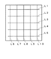
スクライブ装置を用いてガラス基板を小さい基板に分断する場合、ガラス基板に平行に多数のスクライブラインを形成し、更にこれらのスクライブラインと交差させて格子状にスクライブラインを形成する、いわゆるクロススクライブが行われる。クロススクライブでは、例えば図1に示すように、スクライビングホイールを平行に通過させてスクライブラインL1〜L5を形成し、その後テーブルを90°回転させてスクライブラインL6〜L10を形成する。 When a glass substrate is divided into small substrates using a scribing device, so-called cross scribing is performed in which a large number of scribe lines are formed in parallel to the glass substrate, and further, the scribe lines are formed in a lattice shape by crossing these scribe lines. Done. In cross scribing, for example, as shown in FIG. 1, scribe lines L1 to L5 are formed by passing through a scribing wheel in parallel, and then the table is rotated 90 ° to form scribe lines L6 to L10.
脆性材料基板をスクライブするスクライブ方法の1つに、スクライブラインL6〜L10のように脆性材料基板の外側から外側までをスクライブするスクライブ方法がある。これは、スクライビングホイールを脆性材料基板の端より少し外側のポイントにおいて、スクライビングホイールの最下端を脆性材料基板の上面よりも僅かに下方まで降下させる。そしてスクライビングホイールに対して所定の圧力をかけた状態で水平移動させることで脆性材料基板の一方の縁からスクライブを開始し、他方の縁までスクライブするものである。これを以下、外切りスクライブという。外切りスクライブの場合にはスクライブラインが基板の両端に達しているため、スクライブ後のブレイクが容易であるが、スクライブの開始部分で基板に損傷が生じ易いという欠点がある。 As one of scribing methods for scribing a brittle material substrate, there is a scribing method for scribing from the outside to the outside of the brittle material substrate as scribe lines L6 to L10. This lowers the bottom end of the scribing wheel slightly below the top surface of the brittle material substrate at a point slightly outside the end of the brittle material substrate. And scribing is started from one edge of the brittle material substrate by horizontally moving the scribing wheel in a state where a predetermined pressure is applied, and scribing to the other edge. This is hereinafter referred to as outer cutting scribe. In the case of external scribing, since the scribe line reaches both ends of the substrate, break after scribing is easy, but there is a drawback that the substrate is easily damaged at the start of scribing.
又スクライブラインL1〜L5のように、脆性材料基板の内側より内側までをスクライブして外側にはスクライブしないスクライブ方法がある。これは脆性材料基板の縁より少し内側にスクライビングホイールを降下させ、そしてスクライビングホイールに下向きの所定圧力をかけた状態で図中右方向に水平移動させることで、脆性材料基板の内側からスクライブを開始し、他端の内側までスクライブするものである。これを以下、内切りスクライブという。 Further, there is a scribing method such as scribing lines L1 to L5 that scribe from the inside to the inside of the brittle material substrate and do not scribe to the outside. This is done by lowering the scribing wheel slightly inward from the edge of the brittle material substrate, and by horizontally moving the scribing wheel to the right in the state with a predetermined downward pressure on the scribing wheel, starting scribing from the inside of the brittle material substrate. And scribes to the inside of the other end. This is hereinafter referred to as “inner scribe”.
さて、従来より、第1の刃先を用いてスクライブする場合に、ホイールの転動直後には刃先が基板表面で滑ってスクライブラインが形成されない現象が問題視されており、このような状態は「かかりが悪い」状態といわれていた。一方、第2の刃先によれば「かかりが悪い」状態を回避できるが、第1の刃先を用いてスクライブした場合と比較して、分断後のガラスの端面強度が低くなるという問題があり、ガラスの用途によっては分断後の端面処理を必要とする場合もあった。特に近年は、ガラスの用途の拡大、ガラスの薄板化、製品製造の簡素化の要求の点より、「かかりが悪い」状態を回避しつつ、第1の刃先を用いてスクライブした場合と同等の端面強度を得られる技術が求められている。 Conventionally, when scribing using the first cutting edge, the phenomenon that the cutting edge slides on the substrate surface and a scribe line is not formed immediately after rolling of the wheel has been regarded as a problem. It was said to be “bad”. On the other hand, according to the second cutting edge, it is possible to avoid the “bad” state, but there is a problem that the end face strength of the glass after the division is lower than when scribing using the first cutting edge, Depending on the application of the glass, the end face treatment after dividing may be required. In particular, in recent years, from the viewpoint of expanding the application of glass, reducing the thickness of glass, and simplifying the production of products, it is equivalent to the case of scribing using the first cutting edge while avoiding the “bad” state. There is a need for a technique capable of obtaining end face strength.
かかりが悪い場合には、外切りスクライブは可能であっても内切りスクライブができなくなることが多い。またクロススクライブすると、交点付近でスクライブラインが連続しない、いわゆる「交点飛び」が発生する問題があった。例えば図1において、スクライブラインL1〜L5を形成した後、テーブルを回転させスクライブラインL6〜L10を形成すると、スクライブラインの交点でリブマークが終了してしまい、部分的にスクライブラインが形成されない交点飛び現象が発生する場合がある。 If the hook is poor, it is often impossible to perform the inner cut scribe even if the outer cut scribe is possible. Further, when cross-scribing, there is a problem that a so-called “intersection jump” occurs in which the scribe lines are not continuous near the intersection. For example, in FIG. 1, when the scribe lines L1 to L5 are formed and then the table is rotated to form the scribe lines L6 to L10, the rib mark ends at the intersection of the scribe lines, and the intersection skip where the scribe lines are not partially formed. The phenomenon may occur.
この原因は以下のように考えられている。すなわち、スクライブラインを最初に形成したとき、スクライブラインを挟んで両側のガラス表面付近に内部応力が生じる。次いで、既に形成されたスクライブラインをスクライビングホイールが直角に通過するとき、その付近に潜在する内部応力によりスクライビングホイールからガラス基板面に垂直方向に加えられる力が削がれてしまう。そのため、交点付近で後から形成されるべきスクライブラインが形成されないものと考えられる。 This cause is considered as follows. That is, when a scribe line is first formed, an internal stress is generated near the glass surfaces on both sides across the scribe line. Next, when the scribing wheel passes through the scribe line that has already been formed at a right angle, the force applied in the direction perpendicular to the glass substrate surface from the scribing wheel is scraped off due to internal stress existing in the vicinity thereof. Therefore, it is considered that a scribe line to be formed later is not formed near the intersection.
交点飛びがガラス基板に発生すると、ガラス基板は予定していたスクライブライン通りに分離されないため不良品が発生し、生産効率を低下させるといった問題があった。 When the intersection jump occurs on the glass substrate, the glass substrate is not separated according to the intended scribe line, so that a defective product is generated and the production efficiency is lowered.
また、携帯電話等に用いられるガラス基板では、軽量化のため厚みが薄くなっている。厚さが薄い基板に対して外切りスクライブを行うと、スクライビングホイールの基板への乗り上げ時に基板の端面エッジに与える衝撃でエッジに欠けが発生したり、基板自身が割れてしまうので製品の歩留まりが低下する。 In addition, a glass substrate used for a mobile phone or the like is thin for weight reduction. When scribe-cutting is performed on a substrate with a small thickness, chipping may occur due to the impact applied to the edge of the substrate when the scribing wheel is mounted on the substrate, or the substrate itself may be cracked, resulting in increased product yield. descend.
そこで薄いガラス基板ではエッジに欠けが発生しないように、内切りスクライブが要求される。しかし従来の第1の刃先では、かかりが悪いため内切りではスクライブラインが形成できない場合もあった。 Therefore, the inner glass scribe is required so that the edge of the thin glass substrate does not occur. However, since the conventional first cutting edge is poor, there is a case where a scribe line cannot be formed by internal cutting.
一方、特許文献1に記載の第2の刃先は、「かかりの良い」刃先であり、スクライビングホイールの転動直後からスクライブラインを形成することができる。従って第2の刃先を用いることにより、内切りスクライブすることができ、クロススクライブにおいても交点飛びを防止することができる。
On the other hand, the second cutting edge described in
フラットパネルディスプレイ等で要求されるガラス基板の端面強度については、第2の刃先は第1の刃先より端面強度が劣るという問題があった。端面強度はスクライビングホイールの周囲に形成される溝の数に依存しており、溝の数が多くなれば強度が低下する。従って例えば溝の数を300とすると、端面強度が大幅に低下してしまう。 Regarding the end face strength of the glass substrate required for a flat panel display or the like, the second cutting edge has a problem that the end face strength is inferior to that of the first cutting edge. The end surface strength depends on the number of grooves formed around the scribing wheel, and the strength decreases as the number of grooves increases. Therefore, for example, if the number of grooves is 300, the end face strength is significantly reduced.
又第3の刃先を用いてスクライブすると、端面強度は従来の第1の刃先とほぼ同等の結果が得られるが、かかり性能が第2の刃先より劣るという欠点がある。 Further, when scribing using the third cutting edge, the end face strength is almost the same as that of the conventional first cutting edge, but there is a drawback that the starting performance is inferior to that of the second cutting edge.
そこで脆性材料基板の種類にかかわらずかかりがよく、交点飛びが発生しにくい刃先であって端面強度が第1の刃先と同等程度の品質が確保できる刃先が求められている。 Therefore, there is a need for a cutting edge that is easy to apply regardless of the type of the brittle material substrate, that is, a cutting edge that is unlikely to cause jumping at the intersection point and that can ensure the end face strength of the same quality as the first cutting edge.
本発明はこのような従来の問題点に鑑みてなされたものであり、脆性材料基板を切断するに際し、スクライブ開始時のかかりがよく、交点飛びを防止し、脆性材料の分断面の品質(端面強度)が良好なスクライブ性能を発揮するスクライビング方法と、このスクライブ方法を実現するためのスクライビングホイールを提供することを目的とする。 The present invention has been made in view of such conventional problems, and when cutting a brittle material substrate, it is easy to start scribing, prevents intersection jumping, and the quality of the cross section of the brittle material (end face) An object of the present invention is to provide a scribing method that exhibits a scribing performance with good strength and a scribing wheel for realizing the scribing method.
この課題を解決するために、本発明のスクライブ方法は、回転軸を共有する2つの円錐台の底部が交わって円錐稜線が形成された外周縁部を有し、前記円周稜線に沿ってスクライビングホイールを用いてスクライブするときに同時に接することがない間隔に設定された第1,第2の溝を有し、転動しつつ脆性材料基板をスクライブするスクライビングホイールを用いたスクライブ方法であって、前記スクライビングホイールを用いてテスト用脆性材料基板に対してテストスクライブを行い、前記テストスクライブによって形成されたスクライブラインに基づいて、テストスクライブの開始又は終了時点でのスクライビングホイールの第1,第2の溝の回転角度を判別し、前記スクライビングホイールをテストスクライブの終了時と同一の回転角度を保ってダミースクライブを開始し、前記スクライビングホイールの第1,第2の溝が順次前記テスト用脆性材料基板に接する直前までダミースクライブを行い、前記スクライビングホイールについて前記ダミースクライブの終了直後の回転角度を保ってスクライブを開始し、対象となる脆性材料基板をスクライブするものである。 In order to solve this problem, the scribing method of the present invention includes an outer peripheral edge portion in which a bottom portion of two truncated cones sharing a rotation axis intersects to form a conical ridge line, and scribing along the circumferential ridge line. A scribing method using a scribing wheel having first and second grooves set at intervals that do not contact at the same time when scribing using a wheel, and scribing a brittle material substrate while rolling, A test scribe is performed on the brittle material substrate for testing using the scribing wheel, and the first and second scribing wheel at the start or end time of the test scribe is based on the scribe line formed by the test scribe. Determine the rotation angle of the groove and rotate the scribing wheel at the same rotation as the end of the test scribe. The dummy scribe is started while maintaining the degree, and the dummy scribe is performed until immediately before the first and second grooves of the scribing wheel come into contact with the brittle material substrate for testing, and the scribe wheel rotates immediately after the dummy scribe ends. Scribing is started while maintaining the angle, and the target brittle material substrate is scribed.
ここで前記テストスクライブの長さを前記スクライビングホイールの円周長とし、テストスクライブにおける第1,第2の溝の回転角度の判別は、スクライビングホイールの接触位置からスクライブが形成されるまでの距離d1を判別することにより行い、前記ダミースクライブは前記テストスクライブと同一の回転角度から開始し、前記テストスクライブの接触位置からスクライブが形成されるまでの距離と同一の長さをスクライブするようにしてもよい。 Here, the length of the test scribe is defined as the circumferential length of the scribe wheel, and the rotation angle of the first and second grooves in the test scribe is determined by the distance d1 from the contact position of the scribe wheel to the formation of the scribe. The dummy scribe starts from the same rotation angle as the test scribe, and scribes the same length as the distance from the contact position of the test scribe until the scribe is formed. Good.
ここで前記テストスクライブにおける第1,第2の溝の回転角度の判別は、テストスクライブにおいてスクライブが形成されてからスクライブを終了するまでの距離d2を判別することにより行い、前記ダミースクライブの長さは前記スクライビングホイールの円周長の整数倍から前記距離d2を減じた長さとしてもよい。 Here, the rotation angle of the first and second grooves in the test scribe is determined by determining a distance d2 from the scribe formation to the end of the scribe in the test scribe, and the length of the dummy scribe. May be a length obtained by subtracting the distance d2 from an integral multiple of the circumferential length of the scribing wheel.
ここでスクライブする距離が前記スクライビングホイールの円周の整数倍となるように前記スクライビングホイールの直径を設定するようにしてもよい。 Here, the diameter of the scribing wheel may be set so that the scribing distance is an integral multiple of the circumference of the scribing wheel.
この課題を解決するために、本発明のスクライビングホイールは、回転軸を共有する2つの円錐台の底部が交わって円錐稜線が形成された外周縁部を有し、脆性材料基板をスクライブするスクライビングホイールであって、前記円周稜線に沿って形成された第1の溝と、前記第1の溝と隣接する位置に形成された第2の溝と、を有し、前記第2の溝は、スクライビングホイールを用いてスクライブするときに脆性材料基板に前記第1の溝と同時に接することがない間隔に設定されたものである。 In order to solve this problem, a scribing wheel according to the present invention has an outer peripheral edge portion where a bottom portion of two truncated cones sharing a rotation axis intersects to form a conical ridgeline, and scribes a brittle material substrate. The first groove formed along the circumferential ridge line and the second groove formed at a position adjacent to the first groove, the second groove being The distance is set so as not to contact the brittle material substrate simultaneously with the first groove when scribing using a scribing wheel.
ここでスクライブする距離が前記スクライビングホイールの円周の整数倍となるように前記スクライビングホイールの直径を設定するようにしてもよい。 Here, the diameter of the scribing wheel may be set so that the scribing distance is an integral multiple of the circumference of the scribing wheel.
ここで前記スクライビングホイールの第1の溝と、当該溝に最も近く隣接する第2の溝のピッチを100〜10000μm、好ましくは100〜800μm、更に好ましくは100〜400μmとしてもよい。 Here, the pitch of the first groove of the scribing wheel and the second groove closest to the groove may be 100 to 10000 μm, preferably 100 to 800 μm, and more preferably 100 to 400 μm.
このような特徴を有する本発明のスクライビング方法及びスクライビングホイールを用いてスクライビングすることにより、転動させた直後からスクライブを形成することができる。又第1の刃先と同等程度の端面強度を得ることができ、第2の刃先と同等のかかり性能を得ることができる。従って薄い脆性材料基板であっても内切りスクライブをすることができ、又クロススクライブをする場合も交点飛びが生じることがなく、好適に使用することができる。 By scribing using the scribing method and scribing wheel of the present invention having such characteristics, a scribe can be formed immediately after rolling. Further, the end face strength comparable to that of the first cutting edge can be obtained, and the required performance equivalent to that of the second cutting edge can be obtained. Therefore, even a thin brittle material substrate can be internally scribed, and when cross-scribing, the intersection jump does not occur and can be used preferably.
本発明において加工の対象となる脆性材料基板としては、形態、材質、用途および大きさについて特に限定されるものではなく、単板からなる基板または2枚以上の単板を貼り合わせた貼合せ基板であってもよく、これらの表面または内部に薄膜あるいは半導体材料を付着させたり、含ませたりされたものであってもよい。また脆性材料基板の材質としては、ガラス、セラミックス、半導体(シリコン等)、サファイヤ等が挙げられ、その用途としては液晶表示パネル、プラズマディスプレイパネル、有機ELディスプレイパネル、表面電界ディスプレイ(SED)用パネル等の電界放出ディスプレイ(FED)用パネル等のフラットパネルディスプレイ用のパネルが挙げられる。 The brittle material substrate to be processed in the present invention is not particularly limited in terms of form, material, application and size, and a single substrate or a bonded substrate obtained by bonding two or more single plates. The thin film or the semiconductor material may be attached to or included in the surface or the inside thereof. Examples of the material of the brittle material substrate include glass, ceramics, semiconductors (silicon, etc.), sapphire, and the like. Liquid crystal display panels, plasma display panels, organic EL display panels, surface electric field display (SED) panels And a flat panel display panel such as a field emission display (FED) panel.
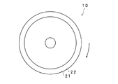
以下、本発明の実施の形態を図面に基づいて詳細に説明する。図2は本実施の形態のスクライビングホイール10の回転軸から見た正面図であり、図3はその側面図である。本実施の形態のスクライビングホイール10は、例えば、従来のスクライブ装置のスクライブヘッドに装着して用いられる。
Hereinafter, embodiments of the present invention will be described in detail with reference to the drawings. FIG. 2 is a front view of the
図2及び図3に示すように、スクライビングホイール10は、回転軸12を共有する二つの円錐台13の底部が交わって円周稜線11が形成された外周縁部14と、円周稜線11に沿って円周方向に形成された複数の溝を有する円板状の部材である。溝の詳細については後述する。スクライビングホイール10は、スクライビングホイール10を軸支するためピンを貫通させる軸孔15を有している。スクライビングホイール10は、円板の外周縁部14に軸心から半径方向に向かって研削加工を施すことによって円周稜線11を形成することができ、収束角度をαとする。スクライビングホイール10の材質は、超硬合金、焼結ダイヤモンド、セラミックスあるいはサーメットが好ましい。
As shown in FIGS. 2 and 3, the
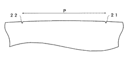
さて本実施の形態においては、円周稜線11に第1の溝21を形成し、この溝21に対して同一の回転方向に隣接する第2の溝22を形成する。図4はこれらの溝21,22を示す部分拡大図である。これらの2つの溝の間隔は、一方の溝が脆性材料基板に接したときに、他方の溝は同時には脆性材料基板に接することがない間隔の中で最小のピッチPとするのがよい。即ちスクライビングホイールを脆性材料基板に圧接すると、その円周稜線11の一部分が基板に食い込む状態となるが、このときスクライビングホイール10の隣接する2つの溝21,22とが同時に接することがない間隔とする。尚これらの溝21,22は、平坦な円周稜線11から概略V字状の溝を深さhで切り欠くことにより形成されている。こうすればスクライブするときに確実に亀裂を継続させ、第1の刃先のガラス破壊強度を維持しながらかかり性能を向上させたスクライビングホイールを実現することができる。ここで、第1の溝と隣接する第2の溝との間隔が小さく、同時に脆性材料基板に接する間隔であると、「かかりの悪い」状態を回避するための効果が低く、且つ分断後の脆性材料基板の端面強度が低下する傾向がある。溝による「かかりの悪い」状態を回避する効果は溝が脆性材料基板に接触しはじめる際の作用の寄与が大きいと考えられるところ、同時に接する間隔であると、第1の溝が接している間に第2の溝が接しはじめることになり、第2の溝の作用が第1の溝の作用によって減殺されることになるため、「かかりの悪い」状態を回避する効果が低くなるものと考えられる。また、溝の間隔が短く、同時に接するような状態では脆性材料基板の端面強度に悪影響を与え易いものと考えられる。一方、第1の溝と隣接する第2の溝との間隔が大きすぎると、脆性材料基板の端面強度の低下は抑制されるが、「かかりの悪い」状態を回避することができなくなる。
In the present embodiment, the
ここで溝21,22の間隔の具体例について説明する。例えばスクライビングホイールの直径を2mmφとすると、その円周稜線11の全周は6.28mmとなる。そしてスクライビングホイールを脆性材料基板に圧接し、2μmだけ刃先を基板に食い込ませるものとすると、この間隔は少なくとも126.4μmとなる。このうちピッチPは126.4μm〜400μmが好ましい。
Here, a specific example of the interval between the
ここで溝21,22の間隔の他の具体例について説明する。例えばスクライビングホイールの直径を3mmφとすると、その円周稜線11の全周は9.42mmとなる。そしてスクライビングホイールを脆性材料基板に圧接し、2μmだけ刃先を基板に食い込ませるものとすると、この間隔は少なくとも135.6μmとなる。このうちピッチPは135.6〜400μmが好ましい。
Here, another specific example of the interval between the
スクライビングホイールは、例えばホイールの外径が1〜20mm、溝21,22の深さが0.5〜5μmであり、円周稜線11の収束角度が85〜140°である。より好ましいスクライビングホイールは、ホイールの外径が1〜5mm、溝21,22の深さが1〜3μmであり、円周稜線11の収束角度が100〜130°である。一般に、切り欠きの深さの深いスクライビングホイールを使用することにより、脆性材料に対するかかり(特にクロススクライブ時の交点とびの少なさ)が良好になる傾向があり、溝の浅いスクライビングホイールを使用することにより、脆性材料の分断面の品質(端面強度)が向上する傾向がある。従ってこのバランスを保つように溝の深さを決定する。具体的には、溝の深さは例えば1〜3μmであることが好ましい。
For example, the outer diameter of the scribing wheel is 1 to 20 mm, the depth of the
さてこの実施の形態では、スクライビングホイール10の全周に1組の溝21,22のみを形成しているため、スクライビングホイール10を脆性材料基板に圧接してもその接触位置によっては溝が接触するまではスクライブが形成できない可能性がある。このため本実施の形態では、以下の方法によってスクライビング開始直後からスクライブが形成できるようにしている。図5はこの手順を示すフローチャートである。
In this embodiment, since only one set of
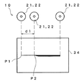
(1)まず図6に示すようにスクライブの対象となる基板とは別のテスト基板30を準備し、スクライビングホイール10を用いてテストスクライブを行う。テストスクライブの長さはスクライビングホイール10の円周に等しい長さとする。このときどの部分から前述したリブマークが形成できているかどうかを検出する。具体的にはLED光源31とCCDカメラ32を用い、画像処理装置33によってスクライブしたラインの形成状態をモニタ画面34に表示させる。図7Aはモニタ表示画面34とスクライブしたラインに対応するスクライビングホイール10の回転角度の一例を示す図である。
(1) First, as shown in FIG. 6, a
(2)次に図7Aに示すモニタ画面から線幅が変化した点を画像処理により求める。線幅が変化した点は溝21,22がテスト基板30に当接してスクライブが形成され始めた部分であると考えられる。
(2) Next, the point where the line width has changed is obtained from the monitor screen shown in FIG. 7A by image processing. The point at which the line width has changed is considered to be a portion where the
(3)スクライビングホイール10がテスト基板30に最初に接触した点をP1とし、線幅が変化した点P2をスクライブが形成され始めた点とし、P1とP2との距離d1を計測する。
(3) A point where the
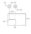
(4)距離d1を計測した後、実際にスクライブする前には、図7Bに示すようにスクライビングホイール10を用いて距離d1、又はこれよりわずかに短い距離だけテスト基板30に対してダミースクライブを行う。テストスクライブの長さをスクライビングホイール10の円周に等しくしているので、溝21,22の回転角度は図7Aに示すようにテストスクライブの開始時と終了時とで同一である。従ってダミースクライブを開始するときには、スクライビングホイール10の回転角度についてはテストスクライブの開始時と同一の角度から、スクライブすることができる。
(4) After the distance d1 is measured and before actual scribing, dummy scribing is performed on the
(5)この後、ワークとなる脆性材料基板に対してスクライブを行う。スクライビングホイールの回転角度はダミースクライブの終了した角度状態からスタートするものとする。こうすればスクライビングホイール10が接触し転動すると、直ちに溝21,22が脆性材料基板に接するため、スクライブを形成することができる。
(5) Thereafter, scribing is performed on the brittle material substrate to be a workpiece. The rotation angle of the scribing wheel starts from the angle state where the dummy scribe is completed. In this way, when the
そして別の脆性材料基板に対してスクライブを行う場合には、上記の(4),(5)を繰り返す。こうすれば常にダミースクライブの長さを一定長d1としてその直後からスクライブすることでスクライブの成立を早めることができる。この実施の形態ではスクライビングホイールに溝21,22のみを形成しているため、従来例の第1の刃先と同等の端面強度とすることができる。又スクライブ開始直後に溝が脆性材料基板に接するため、かかりのよい刃先とすることができる。
And when scribing with respect to another brittle material board | substrate, said (4) and (5) are repeated. In this way, the length of the dummy scribe is always set to the fixed length d1, and the scribe can be established quickly by scribing immediately after that. In this embodiment, since only the
尚ここではテストスクライブのスクライブの長さをスクライビングホイール10の円周に等しいものとしているが、テストスクライブの長さを任意としてもよい。この場合には図8Aに示すようにテストスクライブにおいて線幅が変化した点P2とスクライブを終了した点P3との距離をd2として測定しておく。そして図8Bに示すようにダミースクライブの長さをd3を以下の長さとする。
d3=kdsπ−d2
ここでkは整数、dsはスクライビングホイール10の直径とする。尚kは1でもよく、距離d2が大きい場合はkは2以上の整数となる。こうしてダミースクライブすると、ダミースクライブの終了時点では溝21,22が脆性材料基板に接する直前の同一の回転角度とすることができる。従って実際の脆性材料基板に対してスクライブを開始すると、直ちに脆性材料基板にスクライブを形成することができる。
Here, the length of the test scribe is assumed to be equal to the circumference of the
d3 = kd s π-d2
Here, k is an integer, and d s is the diameter of the
ここでテストスクライブにおいて距離d1又はd2を測定することは、テストスクライブの開始位置における又は終了位置における溝の回転角度を算出することに相当している。 Here, measuring the distance d1 or d2 in the test scribe is equivalent to calculating the rotation angle of the groove at the start position or the end position of the test scribe.
さてスクライブの対象となる脆性材料基板の中には例えば図9に示すように、スクライビング距離Dが常に一定の場合がある。このような場合には距離Dだけスクライブするときスクライビングホイールの回転数は角度まで含めて一定であると考えられる。従ってスクライビングホイールの直径の整数倍が距離Dに等しいように直径を設定する。
D=(n+e)・dsπ
ここでnは任意の整数、eは許容誤差に相当する小数である。こうすれば距離Dだけスクライブするとき常に同一回転数(n+e)だけの転動が行われる。従って図10に示すように、スクライブを開始するときの溝の位置が図10に示すものとすると、距離Dだけスクライブし、終えたときも図10に示す溝の位置とほぼ同一となる。このようにスクライビング距離が決まっている脆性材料基板をスクライブする際に、その距離に応じた直径を有するスクライビングホイールを用いてスクライブすれば、スクライブ毎にダミースクライブをする必要はなくなる。
Now, in some brittle material substrates to be scribed, for example, as shown in FIG. 9, the scribing distance D may be always constant. In such a case, when scribing for the distance D, it is considered that the number of rotations of the scribing wheel is constant including the angle. Accordingly, the diameter is set so that an integer multiple of the diameter of the scribing wheel is equal to the distance D.
D = (n + e) · d s π
Here, n is an arbitrary integer, and e is a decimal number corresponding to an allowable error. In this way, when scribing for a distance D, rolling is always performed by the same number of rotations (n + e). Therefore, as shown in FIG. 10, assuming that the position of the groove at the start of scribing is as shown in FIG. 10, the position of the groove shown in FIG. When scribing using a scribing wheel having a diameter corresponding to the distance when scribing a brittle material substrate whose scribing distance is determined in this way, there is no need to perform a dummy scribing for each scribing.
端面強度を第1の刃先と同等に保つためには溝の数は少ない方が好ましく、本実施の形態では第1,第2の溝の数を1組としている。 In order to keep the end face strength equal to that of the first cutting edge, it is preferable that the number of grooves is small. In the present embodiment, the number of first and second grooves is one set.
本発明によるスクライブ方法及びスクライビングホイールは、スクライブ装置のスクライブヘッドの先端に用いて脆性材料基板をスクライブするために用いることができる。 The scribing method and scribing wheel according to the present invention can be used for scribing a brittle material substrate using the tip of a scribing head of a scribing apparatus.
10 スクライビングホイール
11 円周稜線
12 回転軸
13 円錐台
14 外周縁部
15 軸孔
21,22 溝
DESCRIPTION OF
Claims (7)
前記スクライビングホイールを用いてテスト用脆性材料基板に対してテストスクライブを行い、
前記テストスクライブによって形成されたスクライブラインに基づいて、テストスクライブの開始又は終了時点でのスクライビングホイールの第1,第2の溝の回転角度を判別し、
前記スクライビングホイールをテストスクライブの終了時と同一の回転角度を保ってダミースクライブを開始し、
前記スクライビングホイールの第1,第2の溝が順次前記テスト用脆性材料基板に接する直前までダミースクライブを行い、
前記スクライビングホイールについて前記ダミースクライブの終了直後の回転角度を保ってスクライブを開始し、
対象となる脆性材料基板をスクライブするスクライブ方法。 An interval between the bottoms of the two truncated cones that share the rotation axis is formed so that a conical ridge line is formed, and when the scribing wheel is used for scribing along the circumferential ridge line at the same time A scribing method using a scribing wheel having a set first and second grooves and scribing a brittle material substrate while rolling,
Perform test scribe on the brittle material substrate for testing using the scribing wheel,
Based on the scribe line formed by the test scribe, determine the rotation angle of the first and second grooves of the scribing wheel at the start or end of the test scribe,
A dummy scribe is started by maintaining the same rotation angle as that at the end of the test scribe on the scribing wheel,
Dummy scribing is performed until immediately before the first and second grooves of the scribing wheel contact the brittle material substrate for testing,
The scribing wheel starts scribing while maintaining the rotation angle immediately after the end of the dummy scribe,
A scribing method for scribing a target brittle material substrate.
前記ダミースクライブは前記テストスクライブと同一の回転角度から開始し、前記テストスクライブの接触位置からスクライブが形成されるまでの距離と同一の長さをスクライブする請求項1記載のスクライブ方法。 The test scribe length is the circumferential length of the scribe wheel, and the rotation angle of the first and second grooves in the test scribe is determined by determining the distance d1 from the contact position of the scribe wheel to the scribe formation. To do
The scribing method according to claim 1, wherein the dummy scribe starts from the same rotation angle as the test scribe and scribes the same length as the distance from the contact position of the test scribe to the formation of the scribe.
前記ダミースクライブの長さは前記スクライビングホイールの円周長の整数倍から前記距離d2を減じた長さとする請求項1記載のスクライブ方法。 The determination of the rotation angle of the first and second grooves in the test scribe is performed by determining a distance d2 from when the scribe is formed to when the scribe is completed in the test scribe,
The scribing method according to claim 1, wherein the length of the dummy scribe is a length obtained by subtracting the distance d2 from an integral multiple of a circumferential length of the scribing wheel.
前記円周稜線に沿って形成された第1の溝と、
前記第1の溝と隣接する位置に形成された第2の溝と、を有し、
前記第2の溝は、スクライビングホイールを用いてスクライブするときに脆性材料基板に前記第1の溝と同時に接することがない間隔に設定されたスクライビングホイール。 A scribing wheel for scribing a brittle material substrate, having an outer peripheral edge where a bottom of two truncated cones sharing a rotation axis intersect to form a conical ridge;
A first groove formed along the circumferential ridgeline;
A second groove formed at a position adjacent to the first groove,
The scribing wheel, wherein the second groove is set at an interval that does not contact the brittle material substrate simultaneously with the first groove when scribing using the scribing wheel.
Priority Applications (4)
| Application Number | Priority Date | Filing Date | Title |
|---|---|---|---|
| JP2010216993A JP5118736B2 (en) | 2010-09-28 | 2010-09-28 | Scribing method and scribing wheel |
| CN201110251631.7A CN102416671B (en) | 2010-09-28 | 2011-08-24 | Scribing method and scribing wheel |
| KR1020110085410A KR101286847B1 (en) | 2010-09-28 | 2011-08-26 | Scribing method and scribing wheel |
| TW100130815A TWI480244B (en) | 2010-09-28 | 2011-08-26 | Scribing method and scribing wheel |
Applications Claiming Priority (1)
| Application Number | Priority Date | Filing Date | Title |
|---|---|---|---|
| JP2010216993A JP5118736B2 (en) | 2010-09-28 | 2010-09-28 | Scribing method and scribing wheel |
Publications (2)
| Publication Number | Publication Date |
|---|---|
| JP2012072002A JP2012072002A (en) | 2012-04-12 |
| JP5118736B2 true JP5118736B2 (en) | 2013-01-16 |
Family
ID=45941439
Family Applications (1)
| Application Number | Title | Priority Date | Filing Date |
|---|---|---|---|
| JP2010216993A Expired - Fee Related JP5118736B2 (en) | 2010-09-28 | 2010-09-28 | Scribing method and scribing wheel |
Country Status (4)
| Country | Link |
|---|---|
| JP (1) | JP5118736B2 (en) |
| KR (1) | KR101286847B1 (en) |
| CN (1) | CN102416671B (en) |
| TW (1) | TWI480244B (en) |
Families Citing this family (5)
| Publication number | Priority date | Publication date | Assignee | Title |
|---|---|---|---|---|
| US10351460B2 (en) * | 2012-05-22 | 2019-07-16 | Corning Incorporated | Methods of separating strengthened glass sheets by mechanical scribing |
| JP6201608B2 (en) * | 2013-10-08 | 2017-09-27 | 三星ダイヤモンド工業株式会社 | Scribing method |
| JP6249091B2 (en) * | 2014-03-31 | 2017-12-20 | 三星ダイヤモンド工業株式会社 | Method for dividing brittle material substrate |
| KR101709906B1 (en) | 2016-08-10 | 2017-02-24 | 박진한 | Rotating water discharge cleaning brush |
| KR102073711B1 (en) | 2018-02-14 | 2020-02-05 | 한국미쯔보시다이아몬드공업(주) | Method for inspecting thickness of rib mark |
Family Cites Families (11)
| Publication number | Priority date | Publication date | Assignee | Title |
|---|---|---|---|---|
| TW536527B (en) * | 2000-08-11 | 2003-06-11 | Mitsuboshi Diamond Ind Co Ltd | Cutter for cutting brittle material, scriber using the same and scribing method |
| JP4038431B2 (en) | 2001-03-16 | 2008-01-23 | 三星ダイヤモンド工業株式会社 | Scribing method, cutter wheel, scribing apparatus using the cutter wheel, and cutter wheel manufacturing apparatus for manufacturing the cutter wheel |
| JP4698651B2 (en) * | 2001-03-16 | 2011-06-08 | 三星ダイヤモンド工業株式会社 | Cutter wheel and scribing device using the cutter wheel |
| JP3890992B2 (en) | 2002-01-30 | 2007-03-07 | 株式会社豊田自動織機 | Method and apparatus for forming groove for cutting mother glass substrate |
| CN100418718C (en) * | 2002-11-22 | 2008-09-17 | 三星钻石工业股份有限公司 | Method for dividing substrate and method for manufacturing substrate using such method |
| CN101596721B (en) * | 2002-11-22 | 2012-10-10 | 三星钻石工业股份有限公司 | Substrate-cutting system |
| CN102172991B (en) * | 2004-07-16 | 2015-04-22 | 三星钻石工业股份有限公司 | Cutter wheel and method of manufacturing the same, manual scribing tool, and scribing device |
| KR20060017058A (en) * | 2004-08-19 | 2006-02-23 | 엠.제이.테크(주) | Scribing wheel cutter |
| KR101164851B1 (en) * | 2005-07-06 | 2012-07-11 | 미쓰보시 다이야몬도 고교 가부시키가이샤 | Brittle material scribing wheel, and scribing method, scribing apparatus and scribing tool using such brittle material scribing wheel |
| JP2007152936A (en) * | 2005-11-09 | 2007-06-21 | Nikken Dia:Kk | Wheel cutter for brittle material |
| JP4219945B2 (en) * | 2006-08-10 | 2009-02-04 | トーヨー産業株式会社 | Cutter foil for glass cutting |
-
2010
- 2010-09-28 JP JP2010216993A patent/JP5118736B2/en not_active Expired - Fee Related
-
2011
- 2011-08-24 CN CN201110251631.7A patent/CN102416671B/en not_active Expired - Fee Related
- 2011-08-26 TW TW100130815A patent/TWI480244B/en active
- 2011-08-26 KR KR1020110085410A patent/KR101286847B1/en not_active IP Right Cessation
Also Published As
| Publication number | Publication date |
|---|---|
| TWI480244B (en) | 2015-04-11 |
| TW201213255A (en) | 2012-04-01 |
| CN102416671A (en) | 2012-04-18 |
| KR101286847B1 (en) | 2013-07-17 |
| CN102416671B (en) | 2014-11-05 |
| JP2012072002A (en) | 2012-04-12 |
| KR20120032412A (en) | 2012-04-05 |
Similar Documents
| Publication | Publication Date | Title |
|---|---|---|
| TWI498299B (en) | A scribing material for a brittle material and a method for manufacturing the same, a scribing method using a scribing wheel, a scribing device, and a scribing tool | |
| JP5185412B2 (en) | Method of scribing and dividing brittle material substrate using cutter wheel | |
| JP5479424B2 (en) | Scribing wheel for brittle material, scribing device and scribing tool for brittle material substrate using the same | |
| JP5118736B2 (en) | Scribing method and scribing wheel | |
| TWI511939B (en) | A scribing line, a scribing device, a scribing method, a manufacturing method for a display panel, and a display panel | |
| JP5174112B2 (en) | Scribing wheel |
Legal Events
| Date | Code | Title | Description |
|---|---|---|---|
| A977 | Report on retrieval |
Free format text: JAPANESE INTERMEDIATE CODE: A971007 Effective date: 20120912 |
|
| TRDD | Decision of grant or rejection written | ||
| A01 | Written decision to grant a patent or to grant a registration (utility model) |
Free format text: JAPANESE INTERMEDIATE CODE: A01 Effective date: 20120925 |
|
| A01 | Written decision to grant a patent or to grant a registration (utility model) |
Free format text: JAPANESE INTERMEDIATE CODE: A01 |
|
| A61 | First payment of annual fees (during grant procedure) |
Free format text: JAPANESE INTERMEDIATE CODE: A61 Effective date: 20121019 |
|
| R150 | Certificate of patent or registration of utility model |
Free format text: JAPANESE INTERMEDIATE CODE: R150 |
|
| FPAY | Renewal fee payment (event date is renewal date of database) |
Free format text: PAYMENT UNTIL: 20151026 Year of fee payment: 3 |
|
| LAPS | Cancellation because of no payment of annual fees |
