JP5117828B2 - Drive device - Google Patents
Drive device Download PDFInfo
- Publication number
- JP5117828B2 JP5117828B2 JP2007301963A JP2007301963A JP5117828B2 JP 5117828 B2 JP5117828 B2 JP 5117828B2 JP 2007301963 A JP2007301963 A JP 2007301963A JP 2007301963 A JP2007301963 A JP 2007301963A JP 5117828 B2 JP5117828 B2 JP 5117828B2
- Authority
- JP
- Japan
- Prior art keywords
- voltage
- terminal
- input
- potentiometer
- rated voltage
- Prior art date
- Legal status (The legal status is an assumption and is not a legal conclusion. Google has not performed a legal analysis and makes no representation as to the accuracy of the status listed.)
- Active
Links
- 231100001261 hazardous Toxicity 0.000 claims description 6
- 239000000383 hazardous chemical Substances 0.000 claims description 3
- 239000000155 melt Substances 0.000 claims 2
- 230000004888 barrier function Effects 0.000 description 16
- 239000000463 material Substances 0.000 description 6
- 230000000903 blocking effect Effects 0.000 description 4
- 230000002457 bidirectional effect Effects 0.000 description 3
- 238000007689 inspection Methods 0.000 description 3
- 239000003949 liquefied natural gas Substances 0.000 description 3
- 230000032258 transport Effects 0.000 description 3
- 238000012423 maintenance Methods 0.000 description 2
- 239000003209 petroleum derivative Substances 0.000 description 2
- 238000004804 winding Methods 0.000 description 2
- 241000255777 Lepidoptera Species 0.000 description 1
- 230000003321 amplification Effects 0.000 description 1
- 238000010586 diagram Methods 0.000 description 1
- 239000013056 hazardous product Substances 0.000 description 1
- 238000003199 nucleic acid amplification method Methods 0.000 description 1
- 208000024891 symptom Diseases 0.000 description 1
Images
Landscapes
- Emergency Protection Circuit Devices (AREA)
Description
本発明は、電動ウインチの駆動装置に関するものであり、特に、タンカー等の可燃性危険物を運搬する船舶でも安全に使用可能なウインチの駆動装置に関するものである。 The present invention relates to a drive device for an electric winch, and more particularly to a drive device for a winch that can be safely used even in a ship that transports a flammable dangerous material such as a tanker.
船舶には、船体を岸壁に係留するためのロープ又はワイヤーの繰出し及び巻取りを行うウインチが設けられている。 The ship is provided with a winch for feeding and winding a rope or wire for mooring the hull to the quay.
このウインチは、ワイヤー又はロープを巻回するドラムを回転駆動するモータを備えているが、石油や液化天然ガス等の可燃性危険物を運搬するタンカーでは、電動のウインチを配設した場合、電動モータの駆動制御を行う駆動装置等からの発火により火災が発生する恐れがあるため、ウインチには油圧モータが用いられていた(たとえば、特許文献1参照。)。
ところが、船舶に油圧モータを配設した場合には、当該油圧モータへ動力となる高圧油を供給するための油圧供給用の配管を設ける必要がある。 However, when a hydraulic motor is provided in a ship, it is necessary to provide a hydraulic supply pipe for supplying high-pressure oil as power to the hydraulic motor.
特に、タンカー等の大型船舶にあっては、その船体の大きさから船体の複数個所にウインチを設ける必要があり、これら複数のウインチに対してそれぞれ油圧供給用の配管を設けなければならないため、油圧供給用の配管の総延長が数100メートルにものぼる。 In particular, in large ships such as tankers, it is necessary to provide winches at multiple locations on the hull due to the size of the hull, and piping for supplying hydraulic pressure must be provided for each of these multiple winches. The total length of the hydraulic supply piping is several hundred meters.
油圧モータの保守点検を行う際には、油圧供給用の配管から油を抜き、全ての配管を洗浄した上で点検を行うため、タンカーでは油圧モータの保守点検に多大な時間と労力要するという問題があった。 When performing maintenance and inspection of hydraulic motors, oil is drained from the piping for supplying hydraulic pressure, and all piping is cleaned before inspection. Therefore, tankers require a lot of time and labor for maintenance and inspection of hydraulic motors. was there.
また、油圧モータに換えて、電動モータを用いた場合には、上記したように、駆動装置等からの発火が発生する恐れがあるという問題があった。 Further, when an electric motor is used instead of the hydraulic motor, there has been a problem that ignition from the drive device or the like may occur as described above.
そこで、本発明は、上記課題を解決すべく、電動モータによる駆動が可能でありながら、タンカー等の可燃性危険物を運搬する船舶でも安全に使用可能なウインチの駆動装置を提供することを目的とする。 Accordingly, an object of the present invention is to provide a drive device for a winch that can be driven by an electric motor and can be safely used in a ship carrying a flammable dangerous material such as a tanker, in order to solve the above-described problems. And
請求項1に係る本発明では、可燃性危険物を運搬する船舶に配設され、ワイヤー又はロープを巻回するドラムと前記ドラムを回転駆動する電動モータとを備えたウインチの駆動装置において、前記ウインチを駆動するために操作する操作部と、所定の基準電圧が入力され、前記操作部の操作量に応じた制御信号を出力するポテンショメータと、前記ポテンショメータから出力される制御信号に基づいて、電源から供給される電圧を調整して前記モータへ供給するインバータ装置と、前記ポテンショメータに入力される電圧が所定の定格電圧に達すると、前記ポテンショメータへの前記定格電圧の入力を遮断する遮断器とを有することとした。 In the present invention according to claim 1, in the drive device for a winch, which is disposed on a ship carrying a flammable dangerous material, and includes a drum around which a wire or a rope is wound and an electric motor that rotationally drives the drum. An operation unit operated to drive the winch, a potentiometer that receives a predetermined reference voltage and outputs a control signal corresponding to the operation amount of the operation unit, and a power source based on the control signal output from the potentiometer An inverter device that adjusts the voltage supplied from the motor and supplies the motor to the motor, and a circuit breaker that cuts off the input of the rated voltage to the potentiometer when the voltage input to the potentiometer reaches a predetermined rated voltage. I decided to have it.
また、請求項2に係る本発明では、請求項1に記載の駆動装置において、前記ポテンショメータは、第1の基準電圧が入力される第1端子と、前記第1の基準電圧よりも低い第2の基準電圧が入力される第2端子と、前記操作部の操作量に応じて前記第1の基準電圧と前記第2の基準電圧との間の電圧を前記制御信号として出力する第3端子とを備え、前記遮断器は、前記第1端子へ入力される電圧が前記定格電圧に達したときに、前記第1端子とグランドとを短絡する第1遮断回路と、前記第2端子へ入力される電圧が前記定格電圧に達したときに、前記第2端子とグランドとを短絡する第2遮断回路と、前記第3端子へ入力される電圧が前記定格電圧に達したときに、前記第3端子とグランドとを短絡する第3遮断回路とを有することを特徴とする。 According to a second aspect of the present invention, in the drive device according to the first aspect, the potentiometer includes a first terminal to which a first reference voltage is input and a second terminal that is lower than the first reference voltage. And a third terminal that outputs a voltage between the first reference voltage and the second reference voltage as the control signal according to an operation amount of the operation unit. And the circuit breaker is input to the second terminal and a first circuit that short-circuits the first terminal and the ground when the voltage input to the first terminal reaches the rated voltage. A second cutoff circuit that short-circuits the second terminal and ground when the voltage reaches the rated voltage, and the third input circuit when the voltage input to the third terminal reaches the rated voltage. Having a third cutoff circuit that short-circuits the terminal and ground. And butterflies.
また、請求項3に係る本発明では、請求項2に記載の駆動装置において、前記遮断器は、前記第1端子へ入力される電圧が前記定格電圧に達したときに溶断して、前記第1端子への前記定格電圧の入力を遮断する第1ヒューズと、前記第2端子へ入力される電圧が前記定格電圧に達したときに溶断して、前記第2端子への前記定格電圧の入力を遮断する第2ヒューズと、前記第3端子へ入力される電圧が前記定格電圧に達したときに溶断して、前記第3端子への前記定格電圧の入力を遮断する第3ヒューズとを有することを特徴とする。 According to a third aspect of the present invention, in the driving device according to the second aspect, the circuit breaker is blown when the voltage input to the first terminal reaches the rated voltage, and the first A first fuse that cuts off the input of the rated voltage to one terminal, and blows when the voltage input to the second terminal reaches the rated voltage, and the rated voltage is input to the second terminal. And a third fuse that blows off when the voltage input to the third terminal reaches the rated voltage and blocks the input of the rated voltage to the third terminal. It is characterized by that.
また、請求項4に係る本発明では、請求項1〜3のいずれか1項に記載の駆動装置において、前記遮断器を前記船舶における非危険区域に設けたことを特徴とする。
Moreover, in this invention which concerns on
請求項1に係る本発明では、可燃性危険物を運搬する船舶に配設され、ワイヤー又はロープを巻回するドラムと前記ドラムを回転駆動する電動モータとを備えたウインチの駆動装置において、前記ウインチを駆動するために操作する操作部と、所定の基準電圧が入力され、前記操作部の操作量に応じた制御信号を出力するポテンショメータと、前記ポテンショメータから出力される制御信号に基づいて、電源から供給される電圧を調整して前記モータへ供給するインバータ装置と、前記ポテンショメータに入力される電圧が所定の定格電圧に達すると、前記ポテンショメータへの前記定格電圧の入力を遮断する遮断器とを有することとしたため、万一落雷や内部回路のショートにより、ポテンショメータに定格電圧を超える過電圧が入力されるような事態が生じても、ポテンショメータに入力される電圧が定格電圧に達すると、遮断器が定格電圧のポテンショメータへの入力を遮断して、過電圧の入力に起因したポテンショメータからの発火を防止することができるので、電動モータによる駆動が可能でありながら、タンカー等の可燃性危険物を運搬する船舶でも安全に使用可能なウインチの駆動装置を提供することができる。 In the present invention according to claim 1, in the drive device for a winch, which is disposed on a ship carrying a flammable dangerous material, and includes a drum around which a wire or a rope is wound and an electric motor that rotationally drives the drum. An operation unit operated to drive the winch, a potentiometer that receives a predetermined reference voltage and outputs a control signal corresponding to the operation amount of the operation unit, and a power source based on the control signal output from the potentiometer An inverter device that adjusts the voltage supplied from the motor and supplies the motor to the motor, and a circuit breaker that cuts off the input of the rated voltage to the potentiometer when the voltage input to the potentiometer reaches a predetermined rated voltage. Therefore, an overvoltage exceeding the rated voltage is input to the potentiometer due to a lightning strike or a short circuit in the internal circuit. Even if such a situation occurs, when the voltage input to the potentiometer reaches the rated voltage, the circuit breaker interrupts the input to the rated voltage potentiometer to prevent ignition from the potentiometer due to overvoltage input Therefore, it is possible to provide a drive device for a winch that can be driven by an electric motor and can be safely used even in a ship that carries a flammable dangerous material such as a tanker.
また、請求項2に係る本発明では、請求項1に記載の駆動装置において、前記ポテンショメータは、第1の基準電圧が入力される第1端子と、前記第1の基準電圧よりも低い第2の基準電圧が入力される第2端子と、前記操作部の操作量に応じて前記第1の基準電圧と前記第2の基準電圧との間の電圧を前記制御信号として出力する第3端子とを備え、前記遮断器は、前記第1端子へ入力される電圧が前記定格電圧に達したときに、前記第1端子とグランドとを短絡する第1遮断回路と、前記第2端子へ入力される電圧が前記定格電圧に達したときに、前記第2端子とグランドとを短絡する第2遮断回路と、前記第3端子へ入力される電圧が前記定格電圧に達したときに、前記第3端子とグランドとを短絡する第3遮断回路とを有することを特徴とするため、簡易な構造でありながら、ポテンショメータの第1〜第3端子のうちのいずれかに定格電圧を超える過電圧が入力されることを確実に防止することができる。 According to a second aspect of the present invention, in the drive device according to the first aspect, the potentiometer includes a first terminal to which a first reference voltage is input and a second terminal that is lower than the first reference voltage. And a third terminal that outputs a voltage between the first reference voltage and the second reference voltage as the control signal according to an operation amount of the operation unit. And the circuit breaker is input to the second terminal and a first circuit that short-circuits the first terminal and the ground when the voltage input to the first terminal reaches the rated voltage. A second cutoff circuit that short-circuits the second terminal and ground when the voltage reaches the rated voltage, and the third input circuit when the voltage input to the third terminal reaches the rated voltage. Having a third cutoff circuit that short-circuits the terminal and ground. To the symptoms, with a simple structure, it is possible to reliably prevent the overvoltage that exceeds the rated voltage to any of the first to third terminal of the potentiometer is input.
また、請求項3に係る本発明では、請求項2に記載の駆動装置において、前記遮断器は、前記第1端子へ入力される電圧が前記定格電圧に達したときに溶断して、前記第1端子への前記定格電圧の入力を遮断する第1ヒューズと、前記第2端子へ入力される電圧が前記定格電圧に達したときに溶断して、前記第2端子への前記定格電圧の入力を遮断する第2ヒューズと、前記第3端子へ入力される電圧が前記定格電圧に達したときに溶断して、前記第3端子への前記定格電圧の入力を遮断する第3ヒューズとを有することを特徴とするため、何らかの原因により、第1〜第3遮断器のうちのいずれかが正常に作動しないような場合であっても、第1〜第3端子のうちのいずれかに定格電圧を超える過電圧が入力されることを確実に防止することができる。 According to a third aspect of the present invention, in the driving device according to the second aspect, the circuit breaker is blown when the voltage input to the first terminal reaches the rated voltage, and the first A first fuse that cuts off the input of the rated voltage to one terminal, and blows when the voltage input to the second terminal reaches the rated voltage, and the rated voltage is input to the second terminal. And a third fuse that blows off when the voltage input to the third terminal reaches the rated voltage and blocks the input of the rated voltage to the third terminal. Therefore, even if one of the first to third circuit breakers does not operate normally due to some cause, the rated voltage is applied to one of the first to third terminals. To prevent overvoltage exceeding Can.
また、請求項4に係る本発明では、請求項1〜3のいずれか1項に記載の駆動装置において、前記遮断器を前記船舶における非危険区域に設けたことを特徴とするため、遮断器によるポテンショメータへの定格電圧の入力の遮断を安全に行うことができる。
Moreover, in this invention which concerns on
以下、本発明の一実施形態について、図面を参照して具体的に説明する。なお、ここでは、石油や液化天然ガス等の可燃性危険物を運搬する船舶(以下、「タンカー」という。)に配設されたウインチの駆動装置に対して本発明を適用した場合を例に挙げて説明する。 Hereinafter, an embodiment of the present invention will be specifically described with reference to the drawings. Here, as an example, the present invention is applied to a winch drive device installed in a ship (hereinafter referred to as “tanker”) that transports flammable hazardous materials such as petroleum and liquefied natural gas. I will give you a description.
図1は、本実施形態に係る駆動装置を備えたタンカーを示す説明図であり、図2は、本実施形態に係る駆動装置を示す説明図であり、図3は、本実施形態に係る遮断器を示す説明図である。 FIG. 1 is an explanatory view showing a tanker provided with the drive device according to the present embodiment, FIG. 2 is an explanatory view showing the drive device according to the present embodiment, and FIG. 3 is a block diagram according to the present embodiment. It is explanatory drawing which shows a container.
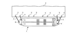
図1に示すように、本実施形態に係るタンカー1は、船首及び船尾に、船体を岸壁2に係留するためのロープ3の繰出し及び巻き取りを行うウインチ4を複数備えている。図中の符号5は、ウインチ4から繰出したロープ3を縛り付けるためのボラード(係船柱)である。
As shown in FIG. 1, a tanker 1 according to the present embodiment includes a plurality of
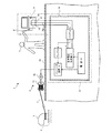
各ウインチ4は、図2に示すように、舫い綱としてのロープを巻回するドラム4aと、このドラム4aを回転駆動する電動モータ4bとを備えている。なお、ここでは、ドラム4aに巻回する線材をロープとしているが、線材はこれに限定するものではなくワイヤーであってもよい。また、本実施形態のウインチ4をアンカー(錨)用として用いる場合には、先端にアンカーが接続された鎖をドラム4aに巻回して使用する。
As shown in FIG. 2, each
また、このウインチ4の電動モータ4bは、駆動装置6から供給される駆動電圧により回転駆動するように構成している。
In addition, the
駆動装置6は、ウインチ4を駆動するために作業者7が操作する操作部としての回動レバー8と、この回動レバー8の操作量に応じた制御信号Sigを出力するポテンショメータ9と、このポテンショメータ9から出力される制御信号Sigに基づいて、電源10から供給される電圧を調整して電動モータ4bへ供給するインバータ装置11とを備えている。
The
図2中の符号12は、ポテンショメータ9から出力された制御信号Sigを所定の増幅率で増幅してインバータ装置11へ出力するアンプであり、符号13は、電源10電圧から第1の基準電圧と、この第1の基準電圧よりも低い第2の基準電圧とを生成してポテンショメータ9へ出力する基準電圧生成器である。
Reference numeral 12 in FIG. 2 is an amplifier that amplifies the control signal Sig output from the
そして、この駆動装置6が備えるポテンショメータ9は、基準電圧生成器13から第1の基準電圧が入力される第1端子15と、第2の基準電圧が入力される第2端子16と、制御信号Sigを出力する第3端子17とを備えており、作業者7が回動レバー8を回動操作すると、その回動操作量に応じて、第1の基準電圧と第2の基準電圧との間の電圧を制御信号Sigとしてアンプ12を介してインバータ装置11へ入力する。
The
インバータ装置11では、電源10から入力される所定の交流電流を一旦直流電流に変化し、その直流電流をポテンショメータ9から入力される制御信号Sigに基づいて周波数変調して交流電流を生成して電動モータ4bに入力して電動モータ4bを駆動する。
In the inverter device 11, a predetermined alternating current input from the power supply 10 is temporarily changed to a direct current, and the direct current is frequency-modulated based on a control signal Sig input from the
すなわち、この駆動装置6では、作業者7による回動レバー8の回動操作量に応じた周波数で所定の駆動電圧を電動モータ4b供給することにより、回動レバー8の回動操作量に応じた回転速度でドラム4aを回転させるように構成している。
That is, in this
特に、本実施形態の駆動装置6は、落雷や内部回路のショート等に起因してポテンショメータ9に定格電圧を超える電圧が入力されることによる発火を防止するための防爆手段として、ポテンショメータ9に入力される電圧が所定の定格電圧に達すると、ポテンショメータ9への定格電圧の入力を遮断する遮断器としてのバリア14を備えている。
In particular, the driving
このバリア14は、ポテンショメータ9の第1端子15、第2端子16、第3端子17のいずれかに入力される電圧が定格電圧に達すると、入力電圧が定格電圧に達した端子(第1端子15、第2端子16、第3端子17)毎に、定格電圧の入力を遮断するように構成している。このバリア14の具体的な回路構成等については、後に詳述する。
When the voltage input to any of the
このように、本実施形態の駆動装置6は、ポテンショメータ9へ入力される電圧が定格電圧に達すると、その定格電圧のポテンショメータ9への入力を遮断するバリア14を備えているため、万一落雷や内部回路のショートにより、ポテンショメータに定格電圧を超える過電圧が入力されるような事態が生じても、ポテンショメータに入力される電圧が定格電圧に達すると、バリア14が定格電圧のポテンショメータ9への入力を遮断して、過電圧の入力に起因したポテンショメータ9からの発火を防止することができるので、電動モータ4bによる駆動が可能でありながら、タンカー1等の可燃性危険物を運搬する船舶でも安全に使用可能なウインチ4の駆動装置6を提供することができる。
As described above, the
また、本実施形態の駆動装置6では、回動レバー8と、この回動レバー8に接続したポテンショメータ9を、作業者7からウインチ4の動作状態を視認しやすい甲板18上に配設すると共に、電源10、インバータ装置11、アンプ12、基準電圧生成器13、バリア14等といった電装部品を甲板18の下方に設けた船舶安全法上の非危険区域19に設けている。
Further, in the
このように、本実施形態では、バリア14を含む電装部品をタンカー1における非危険区域19に配設しているため、船舶安全法において危険区域に指定されているタンカー1の甲板18上に配設したポテンショメータ9へ定格電圧を超える電圧が入力される前に、非危険区域19に配設したバリア14によって、ポテンショメータ9への定格電圧の入力を遮断することができるので、危険区域である甲板18上でポテンショメータ9からの発火による火災の発生を未然に防止することができる。
Thus, in this embodiment, since the electrical components including the
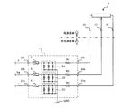
ここで、バリア14の具体的な回路構成及び動作について説明する。このバリア14は、図3に示すように、基準電圧生成器13から第1の基準電圧が入力される第1入力端子20aと、第1の基準電圧をポテンショメータ9の第1端子15へ出力する第1出力端子20bと、基準電圧生成器13から第2の基準電圧が入力される第2入力端子21aと、第2の基準電圧をポテンショメータ9の第2端子16へ出力する第2出力端子21bと、ポテンショメータ9の第3端子17から制御信号Sigが入力される制御入力端子22aと、制御信号Sigをアンプ12へ出力する制御出力端子22bとを備えている。
Here, a specific circuit configuration and operation of the
また、このバリア14では、第1入力端子20aと第1出力端子20bとの間に、第1入力端子20a又は第1出力端子20bに入力される電圧が所定の定格電圧に達すると溶断する第1ヒューズF1と、第1の基準電圧調整用の抵抗R1とを直列に接続している。
Further, in this
さらに、第1ヒューズF1と抵抗R1とを接続する接続線とグランドGNDとの間に、第1入力端子20a又は第1出力端子20bに入力される電圧が所定の定格電圧に達すると、第1ヒューズF1と抵抗R1とを接続する接続線とグランドGNDとを短絡して、ポテンショメータ9が備える第1端子15への定格電圧の入力を遮断する第1遮断回路D1を接続している。
Furthermore, when the voltage input to the
この第1遮断回路D1は、第1ヒューズF1と抵抗R1とを接続する接続線と、グランドGNDとの間に、2つのツェナーダイオードのカソード同士を接続した双方向型のダイオードを3組並列に接続して構成している。 The first cutoff circuit D1 includes three sets of bidirectional diodes in which the cathodes of two Zener diodes are connected in parallel between the connection line connecting the first fuse F1 and the resistor R1 and the ground GND. Connected and configured.
また、このバリア14では、制御入力端子22aと制御出力端子22bとの間に、制御入力端子22a又は制御出力端子22bに入力される電圧が所定の定格電圧に達すると溶断する第2ヒューズF2と、制御信号Sigの電圧調整用の抵抗R2とを直列に接続している。
Further, in this
さらに、第2ヒューズF2と抵抗R2とを接続する接続線とグランドGNDとの間に、制御入力端子22a又は制御出力端子22bに入力される電圧が所定の定格電圧に達すると、第2ヒューズF2と抵抗R2とを接続する接続線とグランドGNDとを短絡して、ポテンショメータ9が備える第3端子17への定格電圧の入力を遮断する第2遮断回路D2を接続している。
Further, when the voltage input to the
この第2遮断回路D2は、第2ヒューズF2と抵抗R2とを接続する接続線と、グランドGNDとの間に、2つのツェナーダイオードのカソード同士を接続した双方向型のダイオードを3組並列に接続して構成している。 The second cutoff circuit D2 includes three pairs of bidirectional diodes in which the cathodes of two Zener diodes are connected in parallel between the connection line connecting the second fuse F2 and the resistor R2 and the ground GND. Connected and configured.
また、このバリア14では、第2入力端子21aと第2出力端子21bとの間に、第2入力端子21a又は第2出力端子21bに入力される電圧が所定の定格電圧に達すると溶断する第3ヒューズF3と、第2の基準電圧調整用の抵抗R3とを直列に接続している。
Further, in the
さらに、第3ヒューズF3と抵抗R3とを接続する接続線とグランドGNDとの間に、第2入力端子21a又は第2出力端子21bに入力される電圧が所定の定格電圧に達すると、第3ヒューズF3と抵抗R3とを接続する接続線とグランドGNDとを短絡して、ポテンショメータ9が備える第2端子16への定格電圧の入力を遮断する第3遮断回路D3を接続している。
Furthermore, when the voltage input to the
この第3遮断回路D3は、第2ヒューズF2と抵抗R2とを接続する接続線と、グランドGNDとの間に、2つのツェナーダイオードのカソード同士を接続した双方向型のダイオードを3組並列に接続して構成している。 The third cutoff circuit D3 includes three pairs of bidirectional diodes in which the cathodes of two Zener diodes are connected in parallel between the connection line connecting the second fuse F2 and the resistor R2 and the ground GND. Connected and configured.
かかる構成により、本実施形態の駆動装置6では、何らかの原因によりポテンショメータ9の第1端子15に、定格電圧を超えるような電圧が入力される場合、その第1端子15に入力される電圧が定格電圧に達した時点で、第1ヒューズF1が溶断するか、若しくは、第1遮断回路D1がポテンショメータ9の第1端子15とグランドGNDとを短絡することによって、第1端子15への定格電圧の入力を遮断することができる。
With this configuration, in the
また、何らかの原因によりポテンショメータ9の第2端子16に定格電圧を超えるような電圧が入力される場合にも同様に、その第2端子16に入力される電圧が定格電圧に達した時点で、第3ヒューズF3が溶断するか、若しくは、第3遮断回路D3がポテンショメータ9の第2端子16とグランドGNDとを短絡することによって、第2端子16への定格電圧の入力を遮断することができる。
Similarly, when a voltage exceeding the rated voltage is input to the
また、何らかの原因によりポテンショメータ9の第3端子17に定格電圧を超えるような電圧が入力される場合にも同様に、その第3端子17に入力される電圧が定格電圧に達した時点で、第2ヒューズF2が溶断するか、若しくは、第2遮断回路D2がポテンショメータ9の第3端子17とグランドGNDとを短絡することによって、第3端子17への定格電圧の入力を遮断することができる。
Similarly, when a voltage exceeding the rated voltage is input to the
このように、本実施形態の駆動装置6では、ポテンショメータ9の第1端子15、第2端子16、第3端子17のいずれかに、定格電圧を超えるような電圧が入力されるような場合に、入力される電圧が定格電圧に達すると、その定格電圧のポテンショメータ9への入力を遮断することができるので、ポテンショメータ9に定格電圧以上の過電圧が入力されることを防止することができ、過電圧によるポテンショメータ9からの発火を未然に防止することができる。
Thus, in the
しかも、ポテンショメータ9への定格電圧の入力を遮断する遮断手段として、第1端子15、第2端子16、第3端子17のそれぞれに、ヒューズ(第1ヒューズF1、第2ヒューズF2、第3ヒューズF3)と、遮断回路(第1遮断回路D1、第2遮断回路D2、第3遮断回路D3)という2種類の遮断手段を設けているため、どちらか一方の遮断手段が正常に作動しなかった場合であっても、他方の遮断手段により、ポテンショメータ9への定格電圧の入力を遮断することができるので、ポテンショメータ9への定格電圧の入力を確実に防止することができ、過電圧によるポテンショメータ9からの発火をより確実に防止することができる。
In addition, as a blocking means for blocking the input of the rated voltage to the
なお、本実施形態において説明したバリア14の具体的な回路構成は、本発明の一例を示したに過ぎず、ポテンショメータ9に入力される電圧が所定の定格電圧に達したときに、その定格電圧のポテンショメータ9への入力を遮断可能な回路構成であれば、任意の回路によりバリア14を構成してもよい。
The specific circuit configuration of the
本実施形態では、石油や液化天然ガス等の可燃性危険物を運搬するタンカー1に配設されたウインチ4の駆動装置6に対して本発明を適用した場合を例に挙げて説明したが、本発明は、これに限定されるものではなく、任意の船舶に配設するウインチの駆動装置に対して適用することができる。
In the present embodiment, the case where the present invention is applied to the
このように本発明の駆動装置を任意の船舶に配設するウインチの駆動装置に対して適用すれば、駆動装置からの発火に起因した船舶火災の発生を未然に防止することがでる。 As described above, when the drive device of the present invention is applied to the drive device of a winch disposed in an arbitrary ship, it is possible to prevent the occurrence of a ship fire due to the fire from the drive apparatus.
1 タンカー
3 ロープ
4 ウインチ
4a ドラム
4b 電動モータ
6 駆動装置
8 回動レバー
9 ポテンショメータ
10 電源
11 インバータ装置
12 アンプ
13 基準電圧生成器
14 バリア
15〜17 第1〜第3端子
19 非危険区域
20a 第1入力端子
20b 第1出力端子
21a 第2入力端子
21b 第2出力端子
22a 制御入力端子
22b 制御出力端子
R1〜R3 抵抗
F1〜F3 第1〜第3ヒューズ
D1〜D3 第1〜第3遮断回路
DESCRIPTION OF SYMBOLS 1
Claims (4)
前記ウインチを駆動するために操作する操作部と、
所定の基準電圧が入力され、前記操作部の操作量に応じた制御信号を出力するポテンショメータと、
前記ポテンショメータから出力される制御信号に基づいて、電源から供給される電圧を調整して前記モータへ供給するインバータ装置と、
前記ポテンショメータに入力される電圧が所定の定格電圧に達すると、前記ポテンショメータへの前記定格電圧の入力を遮断する遮断器と、
を有することを特徴とする駆動装置。 In a winch drive device that is disposed in a ship carrying flammable hazardous materials and includes a drum that winds a wire or rope and an electric motor that rotationally drives the drum,
An operation unit operated to drive the winch;
A potentiometer that receives a predetermined reference voltage and outputs a control signal corresponding to the operation amount of the operation unit;
Based on a control signal output from the potentiometer, an inverter device that adjusts a voltage supplied from a power source and supplies the voltage to the motor;
A circuit breaker that shuts off the input of the rated voltage to the potentiometer when the voltage input to the potentiometer reaches a predetermined rated voltage;
A drive device comprising:
第1の基準電圧が入力される第1端子と、前記第1の基準電圧よりも低い第2の基準電圧が入力される第2端子と、前記操作部の操作量に応じて前記第1の基準電圧と前記第2の基準電圧との間の電圧を前記制御信号として出力する第3端子とを備え、
前記遮断器は、
前記第1端子へ入力される電圧が前記定格電圧に達したときに、前記第1端子とグランドとを短絡する第1遮断回路と、
前記第2端子へ入力される電圧が前記定格電圧に達したときに、前記第2端子とグランドとを短絡する第2遮断回路と、
前記第3端子へ入力される電圧が前記定格電圧に達したときに、前記第3端子とグランドとを短絡する第3遮断回路と、
を有することを特徴とする請求項1に記載の駆動装置。 The potentiometer is
A first terminal to which a first reference voltage is input; a second terminal to which a second reference voltage lower than the first reference voltage is input; and the first terminal according to an operation amount of the operation unit. A third terminal that outputs a voltage between a reference voltage and the second reference voltage as the control signal;
The circuit breaker is
A first cutoff circuit that short-circuits the first terminal and the ground when the voltage input to the first terminal reaches the rated voltage;
A second cutoff circuit that short-circuits the second terminal and the ground when the voltage input to the second terminal reaches the rated voltage;
A third cutoff circuit that short-circuits the third terminal and the ground when the voltage input to the third terminal reaches the rated voltage;
The drive device according to claim 1, wherein:
前記第1端子へ入力される電圧が前記定格電圧に達したときに溶断して、前記第1端子への前記定格電圧の入力を遮断する第1ヒューズと、
前記第2端子へ入力される電圧が前記定格電圧に達したときに溶断して、前記第2端子への前記定格電圧の入力を遮断する第2ヒューズと、
前記第3端子へ入力される電圧が前記定格電圧に達したときに溶断して、前記第3端子への前記定格電圧の入力を遮断する第3ヒューズと、
を有することを特徴とする請求項2に記載の駆動装置。 The circuit breaker is
A first fuse that melts when the voltage input to the first terminal reaches the rated voltage, and blocks the input of the rated voltage to the first terminal;
A second fuse that blows off when the voltage input to the second terminal reaches the rated voltage, and blocks the input of the rated voltage to the second terminal;
A third fuse that melts when the voltage input to the third terminal reaches the rated voltage, and blocks the input of the rated voltage to the third terminal;
The drive device according to claim 2, wherein
Priority Applications (1)
| Application Number | Priority Date | Filing Date | Title |
|---|---|---|---|
| JP2007301963A JP5117828B2 (en) | 2007-11-21 | 2007-11-21 | Drive device |
Applications Claiming Priority (1)
| Application Number | Priority Date | Filing Date | Title |
|---|---|---|---|
| JP2007301963A JP5117828B2 (en) | 2007-11-21 | 2007-11-21 | Drive device |
Publications (2)
| Publication Number | Publication Date |
|---|---|
| JP2009126623A JP2009126623A (en) | 2009-06-11 |
| JP5117828B2 true JP5117828B2 (en) | 2013-01-16 |
Family
ID=40817930
Family Applications (1)
| Application Number | Title | Priority Date | Filing Date |
|---|---|---|---|
| JP2007301963A Active JP5117828B2 (en) | 2007-11-21 | 2007-11-21 | Drive device |
Country Status (1)
| Country | Link |
|---|---|
| JP (1) | JP5117828B2 (en) |
Families Citing this family (3)
| Publication number | Priority date | Publication date | Assignee | Title |
|---|---|---|---|---|
| JP5808128B2 (en) | 2011-03-31 | 2015-11-10 | 三菱重工業株式会社 | Gas fired engine |
| JP5318989B2 (en) * | 2012-05-14 | 2013-10-16 | 株式会社新来島どっく | Arrangement structure of ballast water treatment equipment in tanker |
| CN104118813B (en) * | 2014-07-11 | 2016-08-24 | 常州科研试制中心有限公司 | The mining rope traction transporting equipment control system of wireless operated |
Family Cites Families (4)
| Publication number | Priority date | Publication date | Assignee | Title |
|---|---|---|---|---|
| JPS6151489A (en) * | 1984-08-14 | 1986-03-13 | 日立建機株式会社 | Horizontal withdraw type jib crane |
| JPH0622554A (en) * | 1992-07-07 | 1994-01-28 | Matsushita Electric Ind Co Ltd | Power supply circuit |
| JP2003002280A (en) * | 2001-06-20 | 2003-01-08 | Shinnaka:Kk | Winch for ship |
| JP2005273488A (en) * | 2004-03-23 | 2005-10-06 | Kayaba Ind Co Ltd | Star hydraulic motor for ship deck machinery |
-
2007
- 2007-11-21 JP JP2007301963A patent/JP5117828B2/en active Active
Also Published As
| Publication number | Publication date |
|---|---|
| JP2009126623A (en) | 2009-06-11 |
Similar Documents
| Publication | Publication Date | Title |
|---|---|---|
| JP4623897B2 (en) | Ship propulsion drive system | |
| KR102299078B1 (en) | A shaft generator arrangement of a ship | |
| JP5117828B2 (en) | Drive device | |
| US3196316A (en) | Protective electrical system for remotely powered mobile machines | |
| KR101336067B1 (en) | Apparatus for displaying abnormality of power system | |
| JP4436203B2 (en) | Ship | |
| JP4587305B2 (en) | Ship power supply device and ship power supply switching method | |
| KR200485291Y1 (en) | A general-purpose CO2 welding apparatus with a wire feeder | |
| KR20120002216A (en) | Structure of electrical installation of floating offshore structure | |
| JP2009183124A (en) | Inverter device and electric hoist | |
| JP4605598B2 (en) | Ship power supply device and control method thereof | |
| NO793109L (en) | SYSTEM FOR PROTECTION OF FRONLAND CONSTRUCTIONS | |
| KR20120007737A (en) | Floating Offshore Structures with Power Generation Devices | |
| JP4605599B2 (en) | Ship power supply package and ship power supply method using the same | |
| JP3919160B2 (en) | Automatic recharging device | |
| JP2011020830A (en) | Land power-supply cable reel | |
| JP2006290018A (en) | Ship power supply device and control method thereof | |
| JP2012205498A (en) | Shorting protection for systems having electric machines | |
| KR20160104972A (en) | Apparatus and method for emergency power supply in a ship | |
| KR20160025815A (en) | Apparatus for power supply in offshore plant and offshore plant comprising the apparatus | |
| JP3126684U (en) | Container-mounted power receiving equipment | |
| US8953287B2 (en) | Mobile generator and mobile generator protective device | |
| JPH07222350A (en) | Overload protector for drive motor of digger | |
| WO2011146385A1 (en) | Zone shut-down control system | |
| KR20220031261A (en) | Control apparatus for winch system of vessel |
Legal Events
| Date | Code | Title | Description |
|---|---|---|---|
| A621 | Written request for application examination |
Free format text: JAPANESE INTERMEDIATE CODE: A621 Effective date: 20101004 |
|
| A977 | Report on retrieval |
Free format text: JAPANESE INTERMEDIATE CODE: A971007 Effective date: 20120912 |
|
| TRDD | Decision of grant or rejection written | ||
| A01 | Written decision to grant a patent or to grant a registration (utility model) |
Free format text: JAPANESE INTERMEDIATE CODE: A01 Effective date: 20120918 |
|
| A01 | Written decision to grant a patent or to grant a registration (utility model) |
Free format text: JAPANESE INTERMEDIATE CODE: A01 |
|
| A61 | First payment of annual fees (during grant procedure) |
Free format text: JAPANESE INTERMEDIATE CODE: A61 Effective date: 20121018 |
|
| R150 | Certificate of patent or registration of utility model |
Free format text: JAPANESE INTERMEDIATE CODE: R150 Ref document number: 5117828 Country of ref document: JP Free format text: JAPANESE INTERMEDIATE CODE: R150 |
|
| FPAY | Renewal fee payment (event date is renewal date of database) |
Free format text: PAYMENT UNTIL: 20151026 Year of fee payment: 3 |
|
| R250 | Receipt of annual fees |
Free format text: JAPANESE INTERMEDIATE CODE: R250 |
|
| R250 | Receipt of annual fees |
Free format text: JAPANESE INTERMEDIATE CODE: R250 |
|
| R250 | Receipt of annual fees |
Free format text: JAPANESE INTERMEDIATE CODE: R250 |
|
| R250 | Receipt of annual fees |
Free format text: JAPANESE INTERMEDIATE CODE: R250 |
|
| R250 | Receipt of annual fees |
Free format text: JAPANESE INTERMEDIATE CODE: R250 |
|
| R250 | Receipt of annual fees |
Free format text: JAPANESE INTERMEDIATE CODE: R250 |
|
| R250 | Receipt of annual fees |
Free format text: JAPANESE INTERMEDIATE CODE: R250 |
|
| R250 | Receipt of annual fees |
Free format text: JAPANESE INTERMEDIATE CODE: R250 |