JP5116785B2 - AC motor drive device and motor vehicle - Google Patents
AC motor drive device and motor vehicle Download PDFInfo
- Publication number
- JP5116785B2 JP5116785B2 JP2010040219A JP2010040219A JP5116785B2 JP 5116785 B2 JP5116785 B2 JP 5116785B2 JP 2010040219 A JP2010040219 A JP 2010040219A JP 2010040219 A JP2010040219 A JP 2010040219A JP 5116785 B2 JP5116785 B2 JP 5116785B2
- Authority
- JP
- Japan
- Prior art keywords
- current
- motor
- change rate
- current change
- drive device
- Prior art date
- Legal status (The legal status is an assumption and is not a legal conclusion. Google has not performed a legal analysis and makes no representation as to the accuracy of the status listed.)
- Expired - Fee Related
Links
- 230000008859 change Effects 0.000 claims description 122
- 238000001514 detection method Methods 0.000 claims description 21
- 238000005070 sampling Methods 0.000 claims description 15
- 238000004804 winding Methods 0.000 claims description 8
- 238000006243 chemical reaction Methods 0.000 claims description 4
- 230000004907 flux Effects 0.000 description 76
- 239000013598 vector Substances 0.000 description 56
- 230000006698 induction Effects 0.000 description 38
- 238000010586 diagram Methods 0.000 description 37
- 238000004364 calculation method Methods 0.000 description 19
- 238000000034 method Methods 0.000 description 19
- 230000035945 sensitivity Effects 0.000 description 9
- 239000011162 core material Substances 0.000 description 8
- 230000004069 differentiation Effects 0.000 description 8
- 230000001360 synchronised effect Effects 0.000 description 6
- 238000012937 correction Methods 0.000 description 4
- XEEYBQQBJWHFJM-UHFFFAOYSA-N Iron Chemical group [Fe] XEEYBQQBJWHFJM-UHFFFAOYSA-N 0.000 description 3
- 101100072776 Mus musculus Iqce gene Proteins 0.000 description 3
- 238000007796 conventional method Methods 0.000 description 3
- 238000005516 engineering process Methods 0.000 description 3
- 230000005284 excitation Effects 0.000 description 3
- 230000008569 process Effects 0.000 description 3
- 238000004088 simulation Methods 0.000 description 3
- 238000013178 mathematical model Methods 0.000 description 2
- 230000002441 reversible effect Effects 0.000 description 2
- 230000000630 rising effect Effects 0.000 description 2
- 230000032683 aging Effects 0.000 description 1
- 238000004458 analytical method Methods 0.000 description 1
- 238000004422 calculation algorithm Methods 0.000 description 1
- 230000003247 decreasing effect Effects 0.000 description 1
- 230000000694 effects Effects 0.000 description 1
- 230000020169 heat generation Effects 0.000 description 1
- 238000002347 injection Methods 0.000 description 1
- 239000007924 injection Substances 0.000 description 1
- 229910052742 iron Inorganic materials 0.000 description 1
- 230000004044 response Effects 0.000 description 1
- 239000004065 semiconductor Substances 0.000 description 1
- 239000000243 solution Substances 0.000 description 1
- 230000001052 transient effect Effects 0.000 description 1
Images
Classifications
-
- H—ELECTRICITY
- H02—GENERATION; CONVERSION OR DISTRIBUTION OF ELECTRIC POWER
- H02P—CONTROL OR REGULATION OF ELECTRIC MOTORS, ELECTRIC GENERATORS OR DYNAMO-ELECTRIC CONVERTERS; CONTROLLING TRANSFORMERS, REACTORS OR CHOKE COILS
- H02P21/00—Arrangements or methods for the control of electric machines by vector control, e.g. by control of field orientation
- H02P21/04—Arrangements or methods for the control of electric machines by vector control, e.g. by control of field orientation specially adapted for very low speeds
-
- B—PERFORMING OPERATIONS; TRANSPORTING
- B60—VEHICLES IN GENERAL
- B60L—PROPULSION OF ELECTRICALLY-PROPELLED VEHICLES; SUPPLYING ELECTRIC POWER FOR AUXILIARY EQUIPMENT OF ELECTRICALLY-PROPELLED VEHICLES; ELECTRODYNAMIC BRAKE SYSTEMS FOR VEHICLES IN GENERAL; MAGNETIC SUSPENSION OR LEVITATION FOR VEHICLES; MONITORING OPERATING VARIABLES OF ELECTRICALLY-PROPELLED VEHICLES; ELECTRIC SAFETY DEVICES FOR ELECTRICALLY-PROPELLED VEHICLES
- B60L15/00—Methods, circuits, or devices for controlling the traction-motor speed of electrically-propelled vehicles
- B60L15/02—Methods, circuits, or devices for controlling the traction-motor speed of electrically-propelled vehicles characterised by the form of the current used in the control circuit
- B60L15/025—Methods, circuits, or devices for controlling the traction-motor speed of electrically-propelled vehicles characterised by the form of the current used in the control circuit using field orientation; Vector control; Direct Torque Control [DTC]
-
- B—PERFORMING OPERATIONS; TRANSPORTING
- B60—VEHICLES IN GENERAL
- B60L—PROPULSION OF ELECTRICALLY-PROPELLED VEHICLES; SUPPLYING ELECTRIC POWER FOR AUXILIARY EQUIPMENT OF ELECTRICALLY-PROPELLED VEHICLES; ELECTRODYNAMIC BRAKE SYSTEMS FOR VEHICLES IN GENERAL; MAGNETIC SUSPENSION OR LEVITATION FOR VEHICLES; MONITORING OPERATING VARIABLES OF ELECTRICALLY-PROPELLED VEHICLES; ELECTRIC SAFETY DEVICES FOR ELECTRICALLY-PROPELLED VEHICLES
- B60L15/00—Methods, circuits, or devices for controlling the traction-motor speed of electrically-propelled vehicles
- B60L15/02—Methods, circuits, or devices for controlling the traction-motor speed of electrically-propelled vehicles characterised by the form of the current used in the control circuit
- B60L15/08—Methods, circuits, or devices for controlling the traction-motor speed of electrically-propelled vehicles characterised by the form of the current used in the control circuit using pulses
-
- H—ELECTRICITY
- H02—GENERATION; CONVERSION OR DISTRIBUTION OF ELECTRIC POWER
- H02P—CONTROL OR REGULATION OF ELECTRIC MOTORS, ELECTRIC GENERATORS OR DYNAMO-ELECTRIC CONVERTERS; CONTROLLING TRANSFORMERS, REACTORS OR CHOKE COILS
- H02P21/00—Arrangements or methods for the control of electric machines by vector control, e.g. by control of field orientation
- H02P21/14—Estimation or adaptation of machine parameters, e.g. flux, current or voltage
- H02P21/141—Flux estimation
-
- H—ELECTRICITY
- H02—GENERATION; CONVERSION OR DISTRIBUTION OF ELECTRIC POWER
- H02P—CONTROL OR REGULATION OF ELECTRIC MOTORS, ELECTRIC GENERATORS OR DYNAMO-ELECTRIC CONVERTERS; CONTROLLING TRANSFORMERS, REACTORS OR CHOKE COILS
- H02P21/00—Arrangements or methods for the control of electric machines by vector control, e.g. by control of field orientation
- H02P21/14—Estimation or adaptation of machine parameters, e.g. flux, current or voltage
- H02P21/18—Estimation of position or speed
-
- H—ELECTRICITY
- H02—GENERATION; CONVERSION OR DISTRIBUTION OF ELECTRIC POWER
- H02P—CONTROL OR REGULATION OF ELECTRIC MOTORS, ELECTRIC GENERATORS OR DYNAMO-ELECTRIC CONVERTERS; CONTROLLING TRANSFORMERS, REACTORS OR CHOKE COILS
- H02P6/00—Arrangements for controlling synchronous motors or other dynamo-electric motors using electronic commutation dependent on the rotor position; Electronic commutators therefor
- H02P6/14—Electronic commutators
- H02P6/16—Circuit arrangements for detecting position
- H02P6/18—Circuit arrangements for detecting position without separate position detecting elements
- H02P6/182—Circuit arrangements for detecting position without separate position detecting elements using back-emf in windings
-
- B—PERFORMING OPERATIONS; TRANSPORTING
- B60—VEHICLES IN GENERAL
- B60L—PROPULSION OF ELECTRICALLY-PROPELLED VEHICLES; SUPPLYING ELECTRIC POWER FOR AUXILIARY EQUIPMENT OF ELECTRICALLY-PROPELLED VEHICLES; ELECTRODYNAMIC BRAKE SYSTEMS FOR VEHICLES IN GENERAL; MAGNETIC SUSPENSION OR LEVITATION FOR VEHICLES; MONITORING OPERATING VARIABLES OF ELECTRICALLY-PROPELLED VEHICLES; ELECTRIC SAFETY DEVICES FOR ELECTRICALLY-PROPELLED VEHICLES
- B60L2200/00—Type of vehicles
- B60L2200/26—Rail vehicles
-
- B—PERFORMING OPERATIONS; TRANSPORTING
- B60—VEHICLES IN GENERAL
- B60L—PROPULSION OF ELECTRICALLY-PROPELLED VEHICLES; SUPPLYING ELECTRIC POWER FOR AUXILIARY EQUIPMENT OF ELECTRICALLY-PROPELLED VEHICLES; ELECTRODYNAMIC BRAKE SYSTEMS FOR VEHICLES IN GENERAL; MAGNETIC SUSPENSION OR LEVITATION FOR VEHICLES; MONITORING OPERATING VARIABLES OF ELECTRICALLY-PROPELLED VEHICLES; ELECTRIC SAFETY DEVICES FOR ELECTRICALLY-PROPELLED VEHICLES
- B60L2210/00—Converter types
- B60L2210/20—AC to AC converters
-
- Y—GENERAL TAGGING OF NEW TECHNOLOGICAL DEVELOPMENTS; GENERAL TAGGING OF CROSS-SECTIONAL TECHNOLOGIES SPANNING OVER SEVERAL SECTIONS OF THE IPC; TECHNICAL SUBJECTS COVERED BY FORMER USPC CROSS-REFERENCE ART COLLECTIONS [XRACs] AND DIGESTS
- Y02—TECHNOLOGIES OR APPLICATIONS FOR MITIGATION OR ADAPTATION AGAINST CLIMATE CHANGE
- Y02T—CLIMATE CHANGE MITIGATION TECHNOLOGIES RELATED TO TRANSPORTATION
- Y02T10/00—Road transport of goods or passengers
- Y02T10/60—Other road transportation technologies with climate change mitigation effect
- Y02T10/64—Electric machine technologies in electromobility
-
- Y—GENERAL TAGGING OF NEW TECHNOLOGICAL DEVELOPMENTS; GENERAL TAGGING OF CROSS-SECTIONAL TECHNOLOGIES SPANNING OVER SEVERAL SECTIONS OF THE IPC; TECHNICAL SUBJECTS COVERED BY FORMER USPC CROSS-REFERENCE ART COLLECTIONS [XRACs] AND DIGESTS
- Y02—TECHNOLOGIES OR APPLICATIONS FOR MITIGATION OR ADAPTATION AGAINST CLIMATE CHANGE
- Y02T—CLIMATE CHANGE MITIGATION TECHNOLOGIES RELATED TO TRANSPORTATION
- Y02T10/00—Road transport of goods or passengers
- Y02T10/60—Other road transportation technologies with climate change mitigation effect
- Y02T10/72—Electric energy management in electromobility
Landscapes
- Engineering & Computer Science (AREA)
- Power Engineering (AREA)
- Transportation (AREA)
- Mechanical Engineering (AREA)
- Control Of Ac Motors In General (AREA)
- Control Of Motors That Do Not Use Commutators (AREA)
Description
本発明は、誘導電動機や永久磁石同期電動機などの交流電動機を、零速度近傍の極低速度域にて回転数やトルクを自在に制御するモータ制御技術に関連し、特に電動機の回転子の回転位置角度や速度情報を直接センサによって検出しないセンサレス制御の交流電動機の駆動装置及び電動機車両に関する。 The present invention relates to a motor control technique for freely controlling the number of rotations and torque of an AC motor such as an induction motor and a permanent magnet synchronous motor in an extremely low speed range near zero speed, and in particular, rotation of a rotor of the motor. The present invention relates to a sensorless control AC motor driving apparatus and a motor vehicle in which position angle and speed information are not directly detected by a sensor.
交流電動機を高応答、高精度に制御する場合、電動機のトルクを管理する必要がある。それには、電動機の回転数(同期電動機の場合には、回転子の位置(角度)情報)をセンサによって検出し、さらに電動機の相電流を検出した上で、制御器内部にて電流をトルク電流成分と励磁成分電流を各々独立に分離して制御する必要がある。この技術はベクトル制御として広く用いられている。 When controlling an AC motor with high response and high accuracy, it is necessary to manage the torque of the motor. To do this, the number of rotations of the motor (rotor position (angle) information in the case of a synchronous motor) is detected by a sensor, the phase current of the motor is further detected, and the current is converted into torque current in the controller. It is necessary to separately control the component and the excitation component current separately. This technique is widely used as vector control.
ベクトル制御には、回転子の速度(あるいは位置)情報が必須である半面、これらのセンサによる信頼性の低下、取り付け調整の作業量の増加、コストアップなどが問題になっている。この解決策として、回転子速度・位置情報を直接用いないセンサレス制御技術が開発され、すでに実用化されている。センサレス制御技術は、回転速度が高い領域では、電動機の誘起電圧に基づく手法にて安定に駆動できるが、誘起電圧が小さくなる零速度近傍においては、ベクトル制御を実現するのが非常に困難となっている。零速度近傍のセンサレス制御技術としては、例えば、下記特許文献のような従来例が挙げられる。 In the vector control, the speed (or position) information of the rotor is essential, but there are problems such as a decrease in reliability due to these sensors, an increase in the amount of work for mounting adjustment, and an increase in cost. As a solution to this, a sensorless control technique that does not directly use the rotor speed / position information has been developed and already put into practical use. Sensorless control technology can be driven stably by a method based on the induced voltage of the motor in the region where the rotational speed is high, but it is very difficult to realize vector control near zero speed where the induced voltage is small. ing. As a sensorless control technique in the vicinity of zero speed, for example, a conventional example such as the following patent document can be cited.
下記特許文献は、交流電動機の回転子における突極性を利用した手法であり、回転子位置が変わることでインダクタンスが変化する性質を利用している。このため、電動機の突極性が必須となる。文献2は、誘導電動機を対象としているが、誘導機においても、励磁電流を流すことによって、鉄芯の磁気飽和が発生し、磁気回路にわずかながら突極性が生じるため、それを利用することができる。 The following patent document is a method using the saliency in the rotor of an AC motor, and utilizes the property that the inductance changes as the rotor position changes. For this reason, the saliency of the electric motor is essential. Reference 2 is intended for induction motors. However, even in induction machines, magnetic saturation of the iron core occurs when an exciting current is passed, and a slight saliency is generated in the magnetic circuit. it can.
特許文献1〜3の手法は、これらの突極性を観測するため、意図的に高調波電圧を電動機に印加して電流に変動を与え、その電流変動量に基づいて電動機内部の磁束位置の推定を行う。
In the methods of
例えば、特許文献2における代表図(図1)では、部品番号4の高周波発生器が高調波電圧を発生させて、電流制御器の出力電圧Vγ*に加算されている。また、電動機の電流isを電流センサ12にて検出し、バンドパスフィルタ9(BPF)を介して高周波成分を取り出している。この高周波電流成分から、電動機内部の磁束位置推定を行っている。
For example, in the representative diagram (FIG. 1) in Patent Document 2, the high frequency generator of
交流電動機をベクトル制御する場合、トルクを線形化することが主目的であり、それには電動機内部の磁束位置を検出できればよい。永久磁石同期電動機では、通常、磁束位置と回転子位置は一致しているため、回転子位置センサがあれば磁束位置を検出できるが、センサレスでは何らかの推定演算が必要になる。同期電動機以外の交流電動機である誘導電動機の場合にも、磁束位置が推定できれば「すべり」の大きさが把握でき、それによってベクトル制御が成立する。 In the case of vector control of an AC motor, the main purpose is to linearize the torque, as long as the magnetic flux position inside the motor can be detected. In a permanent magnet synchronous motor, since the magnetic flux position and the rotor position are usually the same, the magnetic flux position can be detected with a rotor position sensor, but some estimation calculation is required without a sensor. Also in the case of an induction motor that is an AC motor other than the synchronous motor, if the magnetic flux position can be estimated, the magnitude of “slip” can be grasped, and thereby vector control is established.
特許文献4は、特許文献1〜3などで行われている高調波電圧の印加量を低減することを目的とした発明であり、外付けに電流変化量の検出器を設けて、その電流変化量から磁束位置を推定演算するものである。電流変化量検出器の構成としては、電動機の電流変化率を初めに検出し、その電流変化率を高調波印加期間だけ積分することで、電流変化量に変換している。
特許文献5は、基本的には特許文献1〜3と同様の考え方であるが、特許文献4と同様に電流変化量を直接検出する手法が記載されている。電流変化率のセンサとして、外付けのインダクタンスを備える例が記載されている。
特許文献6は、特許文献1〜5と同様に電動機の突極性を利用するものである。この発明では、電動機の磁束位置と仮定した位相に高調波電圧を印加し、その時発生する高調波電流をベクトル量として扱い、そのベクトルの方向が高調波印加の方向とずれないように制御することで、電動機の磁束位置と制御上の推定位置とを一致させるものである。
特許文献7は、他の特許文献とは異なり、基本的には高調波の印加は行わないものである。通常のPWM動作によって発生する高調波電流のリプルを検出し、その電流リプルと、電動機の定数から連立方程式を解き、磁束の位置を推定演算する。 Unlike other patent documents, Patent Document 7 basically does not apply harmonics. A ripple of the harmonic current generated by the normal PWM operation is detected, and simultaneous equations are solved from the current ripple and the constants of the electric motor to estimate and calculate the position of the magnetic flux.
特許文献1〜6の方式では、いずれの手法も高調波電圧を意図的に印加する必要がある。交流電動機のベクトル制御の原理に立ち戻れば、本来高調波電圧の印加は不要であり、むしろ電動機駆動装置としてはデメリットも多く発生する。
In the methods of
図29は、高調波の印加を行わない場合の電動機への線間電圧波形(同図(a))と、高調波印加を行った場合の線間電圧波形(同図(b))を比較したものである。理想的なパルス幅変調であれば、基本波の周期に対して、半周期間は正側のパルスのみ、残りの半周期は負側のパルスのみとなり、高調波発生量は最小化される。ところが、意図的に高調波を印加すると、図29(b)のような波形になり、高調波の発生量は一気に増大化する。また、高調波印加の有無により、モータの電流波形は図30(a),(b)のように変化する。 FIG. 29 shows a comparison between the line voltage waveform to the electric motor when the harmonic is not applied (FIG. (A)) and the line voltage waveform when the harmonic is applied (FIG. (B)). It is a thing. In the case of ideal pulse width modulation, only the positive pulse is generated during the half period and only the negative pulse is used for the remaining half period with respect to the period of the fundamental wave, and the amount of harmonic generation is minimized. However, when a harmonic is intentionally applied, a waveform as shown in FIG. 29B is obtained, and the amount of generated harmonics increases at a stretch. Further, the current waveform of the motor changes as shown in FIGS. 30 (a) and 30 (b) depending on whether or not harmonics are applied.
このような高調波の印加に伴い、様々な問題が発生する。例えば、電動機からの電磁騒音が増大化する。電動機磁束の推定感度を上げるためには、高調波電圧の周波数を下げるか、あるいは振幅を増やす必要があり、いずれにしても可聴領域の騒音(数100Hzから数kHz)を増加させることになる。また、電動機駆動電流には、高調波成分が多量に発生することになり、高調波による損失(主に鉄損)が大幅に増加する。損失の増大化は発熱の問題にも直結し、モータ駆動システムを設計する上で、極めて重要な要因となる。 Various problems occur with the application of such harmonics. For example, electromagnetic noise from the electric motor increases. In order to increase the estimated sensitivity of the motor magnetic flux, it is necessary to lower the frequency of the harmonic voltage or increase the amplitude, and in any case, the noise in the audible region (from several hundred Hz to several kHz) will be increased. In addition, a large amount of harmonic components are generated in the motor drive current, and the loss due to the harmonics (mainly iron loss) increases significantly. The increase in loss is directly related to the problem of heat generation, and is an extremely important factor in designing a motor drive system.
文献4では、その高調波電圧の低減を実現しているが、わずかな注入であっても、高調波損失は大きく発生する。通常のパルス幅変調方式(PWM方式)では、搬送波(キャリア)周波数成分は零相成分であるために発生せず、振幅の小さい(搬送波周辺の)測帯波成分のみが電動機電流に含まれる。しかし、意図的に高調波を注入すると、その成分そのものが直接的に高調波電流となって大きく発生し、想定以上の大きな損失となってしまう。
In
文献5では、電流変化率を検出する例が記されているが、発明内容はあくまでも「電流変化量」に対するアルゴリズムであり、電流変化率を直接利用する具体的な手法は書かれていない。
文献7は、特殊なPWMを行わずに、電流リプルから磁束位置を推定するとの記載があるが、実際には、インバータの出力パルス幅が小さくなる低速領域では、パルス幅を拡大するための特殊なPWMが必要となり、結果としては高調波電流を増加させる。また、電流リプルを検出するための外付け回路が必須であり、インバータのスイッチングに伴うリンギングなどを考慮すると、実用的とは言えない。 Reference 7 describes that the magnetic flux position is estimated from the current ripple without performing special PWM. However, in actuality, in the low-speed region where the output pulse width of the inverter is small, a special for increasing the pulse width is described. PWM is required, resulting in increased harmonic current. Also, an external circuit for detecting current ripple is essential, and it cannot be said that it is practical in consideration of ringing associated with switching of the inverter.
さらに、制御器内部にて、電動機の定数から連立方程式を解くようにして磁極位置を演算しているが、近年の電動機は磁気回路の非線形性が強く、電動機定数を「定数」として扱うのが難しくなっているため、この方式を直接用いることは困難であると言える。 Furthermore, the position of the magnetic pole is calculated by solving simultaneous equations from the constants of the motor inside the controller, but in recent years the motor has a strong nonlinearity in the magnetic circuit, and the motor constant is treated as a "constant". Since it is difficult, it can be said that it is difficult to use this method directly.
本願において開示される発明のうち、代表的なものの概要を簡単に説明すれば、次の通りである。 Of the inventions disclosed in the present application, the outline of typical ones will be briefly described as follows.
本発明の代表的な実施の形態に関わる交流電動機の駆動装置は、直流を交流に電力変換するインバータと、前記インバータに接続された交流電動機と、前記インバータに対してパルス幅変調信号を出力し前記インバータを制御する制御器を有する交流電動機の駆動装置であって、前記インバータの線間電圧波形は、交流出力の基本波周期360度に対して、180度期間を連続した正方向のパルス列とし、残りの180度期間を負方向のパルス列として前記交流電動機に電圧を印加する理想的な駆動波形であるものとし、かつ、前記交流電動機の電流、ならびに電流変化率を検出する手段を備えて、該検出値に基づいて前記交流電動機を制御することを特徴とした交流電動機の駆動装置である。 An AC motor driving apparatus according to a typical embodiment of the present invention includes an inverter that converts direct current to alternating current, an AC motor connected to the inverter, and a pulse width modulation signal to the inverter. A drive apparatus for an AC motor having a controller for controlling the inverter, wherein a line voltage waveform of the inverter is a pulse train in a positive direction having a continuous 180 ° period with respect to a fundamental wave period of 360 ° of AC output. The remaining 180 degree period is an ideal drive waveform for applying a voltage to the AC motor as a negative pulse train, and the current of the AC motor, and means for detecting the current change rate, An AC motor driving apparatus that controls the AC motor based on the detected value.
本願において開示される発明のうち、代表的なものによって得られる効果を簡単に説明すれば以下の通りである。 The effects obtained by typical ones of the inventions disclosed in the present application will be briefly described as follows.
交流電動機の内部磁束を推定演算するために、意図的な高調波電圧の印加は行わないため、インバータの出力波形は理想的なパルス幅変調波形となる。この結果、電磁騒音、高調波損失は最小化される。特に、大容量の交流電動機においては、高調波電流の絶対値が大きくなるため、電磁騒音や損失の発生量は劇的に低減される。さらに、交流電動機の過渡インダクタンスを予め数式モデルやデータテーブルとして備えていることで、電動機の磁気回路が非線形に変化する電動機であっても、問題なく駆動することが可能になる。 In order to estimate and calculate the internal magnetic flux of the AC motor, no intentional harmonic voltage is applied, so the output waveform of the inverter is an ideal pulse width modulation waveform. As a result, electromagnetic noise and harmonic loss are minimized. In particular, in a large-capacity AC motor, the absolute value of the harmonic current increases, so that the amount of electromagnetic noise and loss generated is dramatically reduced. Furthermore, since the transient inductance of the AC motor is preliminarily provided as a mathematical model or a data table, even a motor in which the magnetic circuit of the motor changes nonlinearly can be driven without any problem.
以下、本発明の実施の形態について、図面を参照して説明する。 Embodiments of the present invention will be described below with reference to the drawings.
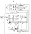
図1は、本発明の第1の実施の形態に関わる交流電動機の駆動装置の構成を表すブロック図である。 FIG. 1 is a block diagram showing a configuration of a drive device for an AC motor according to the first embodiment of the present invention.
この装置は、三相誘導電動機の駆動を目的とするものである。大別すると、この装置はトルク指令発生器1、制御器2、インバータ主回路31やインバータ電源32、ゲート・ドライバ33を含むインバータ3、電流及び電流変化率検出器4、および駆動対象である三相誘導電動機5(以下、誘導機と略)を含んで構成される。
This device is intended to drive a three-phase induction motor. Broadly speaking, this apparatus includes a
トルク指令発生器1は、誘導機5の発生トルク指令Tm*を与える手段であり、制御器2の上位に位置する制御器である。このトルク指令発生装置のさらに上位には、誘導機5の回転数を調整する速度制御器を設ける場合もあるが、本実施例では省略する。
The
制御器2は、トルク指令Tm*に、誘導機5の実際の発生トルクが一致するように、誘導機5への印加電圧の演算を行い、さらに、パルス幅変調を行って、インバータの主回路をスイッチングするゲート信号を出力する。この制御器2は、Id*,Iq*発生器6(d軸電流指令Id*とq軸電流指令Iq*の発生器)、加減算器7a〜7c、d軸電流制御器(IdACR)8、q軸電流制御器(IqACR)9、dq逆変換器10、PWM(パルス幅変調)発生器11、すべり演算器12、電気角位相演算器13、dq変換器14a、14bならびに発明の特徴部である磁束推定器15、速度推定器16から構成される。
The controller 2 calculates the voltage applied to the
次に各部品の動作について説明する。 Next, the operation of each component will be described.
トルク指令発生器1から与えられたトルク指令Tm*に基づいて、Id*,Iq*発生器6にて励磁電流指令Id*とトルク電流指令Iq*が演算される。通常、誘導機5の制御には、Id*を一定に固定し、Iq*をトルク指令Tm*に比例させてトルクを発生させる仕組みとなっている。Id*,Iq*に対して、実際の誘導機の励磁電流成分であるIdc、ならびにトルク電流成分であるIqcとの偏差を加減算器7a,7bにて演算し、この偏差に基づいて、d軸電流制御器(IqACR)8、ならびにq軸電流制御器(IqACR)9にて、d軸,q軸の各電圧指令Vdc*,Vqc*が演算される。
Based on the torque command Tm * given from the
尚、d軸電流制御器8、ならびにq軸電流制御器9は、それぞれの偏差を少なくすることを目的とした制御ブロックであり、比例積分制御など、どのような制御構成であっても問題ない。また、誘導機の場合には、すべり周波数を負荷状態に応じて適切に制御する必要がある。本実施形態においては、すべり演算器12にてId*,Iq*に応じてすべり周波数ωsを演算し、回転速度の推定値ωrcに加算して、誘導機5の駆動周波数であるω1を演算している。
The d-axis
ベクトル制御では、誘導機5の電流を、誘導機5の二次磁束を基準にして回転座標軸上で観測して制御を行う。この回転座標軸の位相角θdcは、駆動周波数ω1を積分器にて積分することで得られる。この演算は、電気角位相演算器13にて行われる。この位相角θdcに基づき、dq変換器14aにて、誘導機5の相電流Iu,Iwをdq座標軸上の電流値Idc,Iqcへと変換する。同様に、dq軸上の電圧指令Vdc*、ならびにVqc*は、三相交流軸上の電圧指令Vu*,Vv*,Vw*へ逆変換される。Vu*,Vv*,Vw*は、PWM発生器11にてパルス幅変調されて、インバータ3へと出力される。
In the vector control, control is performed by observing the current of the
本発明では、誘導機5の相電流における電流変化率dIu、ならびにdIwも検出し、制御器2へ取り入れている。dIuならびにdIwは、dq変換器14bにて、θdcにて座標変換され、dq軸上の電流変化率dIdc、ならびにdIqcとなる。
In the present invention, the current change rates dIu and dIw in the phase current of the
本発明の特徴部である磁束推定器15は、位相角θdc,電流Idc,Iqc,電流変化率dIdc,dIqc,ならびに出力パルスVup,Vvp,Vwpに基づいて、誘導機5内部の磁束推定を行い、誘導機内部の磁束と、制御上の推定磁束とのずれ角に関連する状態量であるΔθeを出力する。この磁束推定器15の詳細は後述する。速度推定器16では、Δθeに基づいて回転速度の推定演算を行う。
The
またPWM発生器11からの信号によって、ゲート・ドライバ33が制御され、インバータ主回路31の各デバイスをオン・オフ制御する。インバータ主回路部31は、6個のスイッチング素子Sup〜Swnで構成される。また、電流検出/電流変化率検出器4が、U相、ならびにW相に取り付けられ、相電流と、相電流の変化率の検出を行っている。
Further, the
電流検出/電流変化率検出器4は、図2に示すような構造となっている。電流検出/電流変化率検出器4は、インバータ3と誘導機5の接続線が巻かれたコア材41、コア材41の内部磁束を検出し、相電流に比例した電圧を発生させるホール素子42、ホール素子の電圧を増幅するアンプ43、コア材41に巻かれた補助巻線44、補助巻線の起電圧を増幅するアンプ45からなる。通常の電流センサ(ホールCT)は、コア材41、ホール素子42、アンプ43によって構成されており、アンプ43の出力が電流検出値となる。本発明では、コア材に補助巻線44を施し、その起電圧が電流変化率に比例することから、電流変化率dIuを直接検出する。
The current detection / current
電流変化率は、電流検出値(例えばIu)を一旦制御器に読み込み、それに対して微分処理を行えば、検出することは不可能ではない。ただし、そのためにはいくつかの課題がある。まず、第一に、電流検出の分解能を高くしなければならない点である。電流検出は、アナログ回路が主体であり、1%程度の検出誤差は必ず存在する。それに対して、電流変化量は数%であり、十分な分解能が得られない。また、変化量を得るためには、ある程度の時間差をおいて2点間の電流値を検出する必要があるため、狭い幅のパルスを印加した場合にはこの時間差を得ることが難しくなる。 It is not impossible to detect the current change rate once a current detection value (for example, Iu) is once read into the controller and subjected to differentiation processing. However, there are some problems to do so. First, the current detection resolution must be increased. The current detection is mainly an analog circuit, and there is always a detection error of about 1%. On the other hand, the amount of current change is several percent, and sufficient resolution cannot be obtained. Further, in order to obtain the amount of change, it is necessary to detect the current value between two points with a certain time difference, so that it is difficult to obtain this time difference when a pulse with a narrow width is applied.
第二に、微分処理自体の誤差要因が挙げられる。制御器で行う微分は、原理的には不完全微分にならざるを得ないため、必ず誤差が含まれる。不完全微分を完全微分に近づけるほど、原理的に精度は向上するが、検出値に含まれるノイズの影響で誤差成分を拡大する恐れがある。 Secondly, there is an error factor of the differentiation process itself. The differentiation performed by the controller must be an incomplete differentiation in principle, so an error is always included. As the incomplete differentiation becomes closer to the complete differentiation, the accuracy is improved in principle, but there is a possibility that the error component is enlarged due to the influence of noise included in the detection value.
本発明では、電流検出/電流変化率検出器4によって、電流変化率そのものを、直接、高感度で検出する。これによって、「差分」を取る必要がなくなるため、制御上の制約条件が大幅に改善されることになる。狭いパルス幅であっても、制御器内に「変化率」として読み込むことが可能になる。
In the present invention, the current change rate itself is directly detected with high sensitivity by the current detection / current
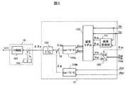
次に、本発明の特徴部である磁束推定器15の詳細を、図3から図5を用いて説明する。図3は、磁束推定器15、ならびに速度推定器16の内部ブロック図を示したものである。図3において、磁束推定器では、電流Idc、ならびにIqcから、磁束初期値演算器151にて、d,qそれぞれの軸の磁束初期値Φds,Φqsを演算する。また、位相θdcを用いて、dq変換器153にてPWMパルスをdq軸上の電圧Vds,Vqsに変換し、これらの状態量Idc,Iqc,Φds,Φqs,Vds,Vqsを磁束モデル演算器152に入力する。磁束モデル152では、誘導機5の内部磁束をシミュレーションして、電流変化率dIdce、ならびにdIqceを計算する。この電流変化率から、d軸を基準とした位相をアークタンジェント演算器154aにて計算して、電流変化率位相推定値δdIeを計算する。
Next, details of the
同様に、電流変化率を直接検出した値であるdIdc,dIqcについても、アークタンジェント演算器154bにて位相角δdIを求める。δdIとδdIeは、本来、一致すべきものである。両者の偏差Δθeが存在するのであれば、それは磁束位置にずれがあるからにほかならない。よって、両者を一致させるように回転速度を修正すればよい。尚、δdIeとδdIは、PWMパルスの状態によって大きさが異なるため、フィルタ155によって安定化している。速度推定器では、Δθeが零になるように速度推定値ωrcを出力する。図3において、比例積分制御器(PI制御器)161にて、Δθeが零になるように制御をかけている。Δθeへの指令としては、零発生器162が「零」を与えている。
Similarly, with respect to dIdc and dIqc, which are values obtained by directly detecting the current change rate, the
図4は、磁束モデル152の内部を示したものである。抵抗設定器1521a、1521bにて、誘導機5の巻き線抵抗分の電圧降下を計算し、その後、印加電圧を積分することで、誘導機5の内部磁束をリアルタイムで演算している。積分器1522a,1522bは、それぞれΦds,Φqsを初期値として、誘導機5内部の磁束変化を計算する。d軸とq軸のそれぞれの磁束マップ1であるIdマップ1523a,Iqマップ1523bに基づき、電流値Idce,Iqceが演算される。これらの動作は、誘導機5の内部状態をシミュレーションしているに過ぎないが、各々のマップは、磁気回路の飽和特性も考慮したものである必要がある。あるいは、マップの変わりに、磁気飽和特性を数式モデル化したものでも問題ない。電流推定値Idce,Iqceは電流値そのものであるため、これを変化率に変換する。変化率は、不完全微分器1524a,1524bにて行われる。シミュレーション上の微分であれば、ノイズの影響は特に大きな問題にはならずに処理することが可能である。
FIG. 4 shows the inside of the
図5に、PWMパルスから、電流変化率までの波形例を示す。同図(a)は、PWMパルスを作成する際の三角波キャリア、ならびに電圧指令Vu*,Vv*,Vw*である。それぞれの電圧指令と三角波キャリアの大小関係からPWMパルスが作成され、それに基づいて、同図(b)のような相電圧がインバータから出力される。線間電圧は、同図(c)のような波形になる。この結果、各相電流は同図(d)〜(f)となり、PWM波形にリンクして脈動電流が発生することになる。この脈動電流の変化率、すなわち微分値は、同図(g)〜(i)になる。これらの電流変化率をdq軸上で観測すると、印加電圧とその時の磁束位置に依存して、ある特定の方向を示すベクトルとなる。これと同様のシミュレーションを、磁束推定器15の内部でも行って電流変化率のベクトルを求め、実検出値との比較を行うことで、磁束位置のずれ分が推定できる。すなわち、磁束推定器15では、図5(g)〜(i)を、dq軸上で推定演算していることになる。磁束推定値の誤差に相当するΔθeを零にできれば、センサレス制御が成立することになる。
FIG. 5 shows a waveform example from the PWM pulse to the current change rate. FIG. 4A shows a triangular wave carrier when generating a PWM pulse, and voltage commands Vu *, Vv *, and Vw *. A PWM pulse is created from the magnitude relationship between each voltage command and the triangular wave carrier, and based on this, a phase voltage as shown in FIG. The line voltage has a waveform as shown in FIG. As a result, each phase current becomes (d) to (f) in the figure, and a pulsating current is generated linked to the PWM waveform. The rate of change of the pulsating current, that is, the differential value is shown in FIGS. When these current change rates are observed on the dq axis, a vector indicating a specific direction is obtained depending on the applied voltage and the magnetic flux position at that time. A simulation similar to this is also performed inside the
本発明によれば、誘導電動機の相電流に対して、電流変化率を直接検出することで、特に高調波を印加することなく、磁束位置の推定が可能であることを示した。 According to the present invention, it has been shown that the position of the magnetic flux can be estimated without particularly applying a harmonic by directly detecting the current change rate with respect to the phase current of the induction motor.
次に本発明の実施例2について説明する。 Next, a second embodiment of the present invention will be described.
第1の実施の形態では、制御器2がアナログ回路で実現するイメージで説明したため、デジタル制御で実現するには、高速処理が必須になる。無論、専用のゲートロジックを用いれば、デジタル化での実現も不可能ではないが、回路規模としては膨大なものになってしまうであろう。 In the first embodiment, since the controller 2 is described as an image realized by an analog circuit, high-speed processing is essential to realize it by digital control. Of course, if dedicated gate logic is used, digitalization is not impossible, but the circuit scale will be enormous.
実施例2では、産業用途等で使用されるマイコンを前提に、実用的な例を図6から図10を用いて示す。 In the second embodiment, a practical example is shown with reference to FIGS. 6 to 10 on the premise of a microcomputer used for industrial use.
図6は、実施例2の特徴部分である制御器2Bのブロック構成図である。本制御器2Bを、図1における制御器2の代わりに導入することで、実施例2となる。
FIG. 6 is a block diagram of the
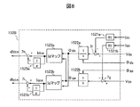
図6において、部品番号6〜14、ならびに16のブロックに関しては、図1に示した同じ番号のものと同一のものである。本実施例の特徴部分は、磁束演算器15B、ならびにサンプルホールド回路17、トリガ発生回路18である。図7に磁束推定器15Bの内部ブロック図を、図8に磁束モデル152Bの内部ブロック図を示す。ここでも、実施例1における図3、ならびに図4と同じ番号のものは、同一のものである。図7では、図3におけるフィルタ155が削除され、ベクトル選択器156が新たに加えられている。また、図8においては、図4における不完全微分器1524a,1524bに代わって、遅れ要素1525a,1525bと加減算器7h、7iが加えられている。それ以外は、実施例1と同じである。
In FIG. 6,
次に、本実施例2の動作原理について説明する。 Next, the operation principle of the second embodiment will be described.
低速で誘導機5を駆動する場合、誘導機への印加電圧の基本波振幅は小さくなる。これは、誘導機5の逆起電圧が回転速度に比例するためであり、回転機の原理上このようになる。印加電圧の振幅が低下した結果、インバータのPWMパルスも非常に狭くなっていく。この様子を図9に示す。図9は、図5にて示したPWM波形と、そのときの電流、ならびに電流変化率の一部分(三角波キャリアが減少方向である部分)を、印加電圧が低い条件で描き改めたものである。
When the
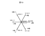
インバータの出力電圧(b)は、各相のデバイスが、上側がオンするのか、下側がオンするのかの2通りであり、3相まとめると、全部で8通りのスイッチングパターンとなる。それをベクトル表現したものが、図10である。V(x,y,z)のように表記した各ベクトルは、各相のスイッチ状態を表している。例えば、V(1,0,0)は、U相が1(すなわち、上側のスイッチがオン)、V相、W相が0(下側のスイッチがオン)の状態を表している。これを図9に当てはめると、この期間は、V(0,0,0)から始まり、V(1,0,0)、V(1,0,1)を得て、V(1,1,1)で終了する。このときの線間電圧は、図9(c)に示す通りであり、V(0,0,0)ならびにV(1,1,1)(これらを零ベクトルと呼ぶ)以外の電圧ベクトルにおいて、線間にパルス電圧が印加されていることがわかる。 The output voltage (b) of the inverter has two types of devices in which the upper side is turned on or the lower side is turned on for each phase device. FIG. 10 is a vector representation of this. Each vector expressed as V (x, y, z) represents the switch state of each phase. For example, V (1, 0, 0) represents a state in which the U phase is 1 (that is, the upper switch is on), the V phase and the W phase are 0 (the lower switch is on). When this is applied to FIG. 9, this period starts from V (0,0,0), V (1,0,0), V (1,0,1) are obtained, and V (1,1,0) is obtained. End with 1). The line voltage at this time is as shown in FIG. 9C, and in voltage vectors other than V (0, 0, 0) and V (1, 1, 1) (these are called zero vectors) It can be seen that a pulse voltage is applied between the lines.
回転速度が極端に低い場合、これら零ベクトル以外のベクトルの出力期間が非常に短くなる。図9では、V(1,0,0)の出力期間をT1,V(1,0,1)の出力期間をT2としている。回転数が低い条件では、誘導機3の逆起電圧は小さく、パルス電圧は非常に大きな外乱パルスのように作用する。図9(d)〜(f)に示すように、パルス印加期間において、最も大きな電流変化を示す。この時の電流変化率は、同図(g)〜(i)のようになる。
When the rotational speed is extremely low, the output period of vectors other than these zero vectors becomes very short. In FIG. 9, the output period of V (1, 0, 0) is T1, and the output period of V (1, 0, 1) is T2. Under the condition that the rotational speed is low, the back electromotive voltage of the
極低速域のセンサレスを行うには、電流変化率を捕らえる必要がある。その場合、図9に示すように、パルス印加時の電流変化率が最も大きく、また感度が高いことがわかる。よって、この期間のみの電流変化率を捉えれば、高感度に位置推定が可能となる。例えば、図9におけるT1の期間ならば、T2よりもパルス幅が長いため、電流変化率を捕らえやすい。このような原理に基づいて、制御系を構成したのが、第2の実施形態である。 In order to achieve sensorless operation in the extremely low speed range, it is necessary to capture the current change rate. In that case, as shown in FIG. 9, it can be seen that the rate of change of current during pulse application is the largest and the sensitivity is high. Therefore, if the current change rate only during this period is captured, the position can be estimated with high sensitivity. For example, in the period of T1 in FIG. 9, since the pulse width is longer than T2, it is easy to capture the current change rate. In the second embodiment, the control system is configured based on such a principle.
図6において、三相電圧指令Vu*,Vv*,Vw*の大小関係から、最も幅の広い電圧ベクトル(零以外のベクトル)の印加タイミングを計算し、そのタイミングにあわせてサンプル/ホールドを行うトリガ信号を、トリガ発生器18にて発生させる。それに従って、サンプル/ホールド回路17にて、電流変化率のサンプルホールドを実施する。すなわち、図9(g)、(i)のサンプリングを実施する。
In FIG. 6, the application timing of the widest voltage vector (vector other than zero) is calculated from the magnitude relationship of the three-phase voltage commands Vu *, Vv *, Vw *, and sampling / holding is performed in accordance with the timing. A trigger signal is generated by the
磁束推定器15Bでは、ベクトル選択器156において、電圧指令Vu*,Vv*,Vw*の大小関係から、パルス幅の広いベクトルを選択し、その電圧をdq変換器153に与える。磁束モデル152Bでは、特定の電圧ベクトルについてのみの磁束推定、電流変化率の推定演算を実施する。
In the
磁束モデル152Bでは、図4の実施例と同様にシミュレーションを行うが、電圧ベクトルが一つに特定されているため、演算処理は大幅に簡略化される。Idマップ1523a、/qマップ1523bから出力される電流推定値Idce,Iqceは、予め計算しておいた初期値(遅延器1525a,1525b)との差分を取って、電流変化率dIdce,dIqceが求められる。
In the
このように、第2の実施形態では、零ベクトル以外の電圧ベクトルが印加された瞬間をサンプリングし、誘導機5の内部磁束位置を推定演算する。サンプリング回数をキャリアの半周期間に対して、1回で済むため、汎用のマイコンを適用することが可能となる。
Thus, in the second embodiment, the moment when a voltage vector other than the zero vector is applied is sampled, and the internal magnetic flux position of the
次に本発明の実施例3について説明する。 Next, a third embodiment of the present invention will be described.
実施例1,2では、制御対象が誘導電動機であったが、実施例3では、永久磁石型動機電動機(以下、PMモータと略)を適用する。PMモータは、誘導機に比べて小型・高効率が実現できるため、今後、適用用途は拡大されていくものと予想されている。 In the first and second embodiments, the control object is an induction motor, but in the third embodiment, a permanent magnet type motor (hereinafter abbreviated as PM motor) is applied. Since PM motors can be smaller and more efficient than induction machines, the application is expected to expand in the future.
図11は第3の実施形態の構成図である。実施例2(図6)をベースに記載している。制御器2Cは、図6の制御器2Bとほぼ同じであり、すべり演算器12を削除した以外、何も変えていない。また、電動機がPMモータ5Cになっている。
FIG. 11 is a configuration diagram of the third embodiment. Example 2 (FIG. 6) is described as a base. The controller 2C is substantially the same as the
PMモータでは、駆動周波数ω1と、回転数の周波数ωrcが必ず同期しているため、すべり周波数を加算する必要がなく、制御構成はよりシンプルになっている。すなわち、すべり演算器12を排除するのみで、PMモータの駆動システムを構成することができる。その際、磁束モデル152、あるいは152BにおけるIdマップ,Iqマップを、PMモータに合わせて修正する必要がある。逆に言えば、そこさえ変更すれば、PMモータの駆動が可能である。
In the PM motor, since the driving frequency ω1 and the frequency ωrc of the rotational speed are always synchronized, it is not necessary to add the slip frequency, and the control configuration is simpler. In other words, a PM motor drive system can be configured simply by eliminating the
次に本発明の実施例4について説明する。 Next, a fourth embodiment of the present invention will be described.
実施例2では、サンプリング回数を三角波キャリアの半周期に対して、一回のみで磁束の位置推定が可能な手法について説明した。実施例4では、キャリア半周期に対してサンプリングを2回行うものである。 In the second embodiment, a method has been described in which the position of the magnetic flux can be estimated only once with respect to the half cycle of the triangular wave carrier. In the fourth embodiment, sampling is performed twice for a carrier half cycle.
零ベクトル以外の電圧ベクトルは、通常のPWMであれば必ず2回出力されている。例えば、図9に示したように、V(1,0,0)とV(1,0,1)の二つが、キャリア半周期間内に出力されている。これら2つの電圧ベクトルを用いることで、より、感度の高い検出が可能となる。感度の高さは、そのまま精度を上げることになるため、より理想に近いベクトル制御をセンサレスにて実現できることになる。 Voltage vectors other than the zero vector are always output twice in the case of normal PWM. For example, as shown in FIG. 9, two of V (1, 0, 0) and V (1, 0, 1) are output within the carrier half cycle. By using these two voltage vectors, detection with higher sensitivity becomes possible. Since the high sensitivity directly increases the accuracy, vector control closer to the ideal can be realized without a sensor.
これらの原理について、図12〜16を用いて説明する。 These principles will be described with reference to FIGS.
図12は、実施例4の特徴部分である制御器2Dのブロック構成図である。本制御器2Dを、図11における制御器2Cの代わりに導入することで、実施例4となる。尚、すべり演算器12を付加すれば、実施例1,2同様に、誘導機の駆動にも適用は可能である。
FIG. 12 is a block diagram of a
図12において、部品番号6〜14、ならびに16のブロックに関しては、図1、あるいは図11に示した同じ番号のものと同一のものである。本実施例の特徴部分は、Δθeの演算経路が2通りある点である。一つは、トリガ発生器18Daのトリガ信号を受けて、電流変化率dIu,dIwをサンプルホールドするサンプル/ホールド17aと、その値を座標変換するdq変換器14b、そのdq軸上の電流変化率を取り込んでΔθe1を演算する磁束推定器15Baである。同様の演算経路がもうひとつ存在し、こちらは、トリガ発生器18Db、サンプル/ホールド17b、dq変換器14c、磁束推定器15Bbを介してΔθe2を演算する。
In FIG. 12, the blocks having the
両者の差異は、どの電圧ベクトルが印加されたときの電流変化率を利用するかの差になっている。前述のように、電圧ベクトルは、零ベクトル以外に2つ存在し、その両者の電圧ベクトル印加時において電流変化率を検出する。新たに加えられたΔθe選択器19では、dq軸上の電流変化率の大きさを比較し、どちらの変化率に基づいて演算を行うかの判別をする。スイッチ20にて、その切替を行っている。
The difference between the two is the difference in which voltage vector is used when the current change rate is applied. As described above, there are two voltage vectors other than the zero vector, and the current change rate is detected when both voltage vectors are applied. The newly added
Δθe選択器19では、下記演算を行って、電流変化率の大きさを比較する。
上記、数1と数2の結果を比較し、大きさの大きな方のΔθeを用いることにする。電流変化率の大きさが大きいと言うことは、それだけ感度が高いという意味であり、推定演算の誤差が少ないことを意味する。この原理について、さらに詳しく説明する。
The above results of
図13(a)は、U,V,Wの三相の固定座標と、dq座標(回転座標)を同時に記載したものである。d軸上に磁束Φmがあるものとすると、逆起電圧EmはΦm対して90度進んだ位相、すなわちq軸上に存在することになる。電流I1の位相と電圧V1の位相を同図のように仮定する。このV1に対して、PWMによってインバータが出力する電圧ベクトルは、例えば図13(b)のようになる。零ベクトルと、電圧ベクトルV(1,0,0)、ならびにV(1,0,1)の三点に囲まれた領域内にV1あれば、これら3つのベクトルを用いてスイッチングが行われることになる。 FIG. 13A shows three-phase fixed coordinates of U, V, and W and dq coordinates (rotation coordinates) at the same time. Assuming that there is a magnetic flux Φm on the d-axis, the back electromotive force Em exists on the phase advanced by 90 degrees with respect to Φm, that is, on the q-axis. The phase of the current I1 and the phase of the voltage V1 are assumed as shown in FIG. With respect to this V1, the voltage vector output from the inverter by PWM is, for example, as shown in FIG. If V1 is in a region surrounded by three points of zero vector, voltage vector V (1, 0, 0), and V (1, 0, 1), switching should be performed using these three vectors. become.
図14は、電圧ベクトルV(1,0,0)が印加された瞬間のベクトル図を示したものである。仮に、電動機のインダクタンスが完全に一様であるとすると、印加された電圧ベクトルの方向に、電流の変化は発生する(図14(a))。その場合には、位置推定は不可能である。実際には、磁束Φmが存在する位相において、磁気飽和によってインダクタンスが低下しているため、図14(b)のように、電流変化率のベクトルdIは、Φmに近い方向にずれて発生する。このずれる度合いによって、磁束位置が推定可能となる。 FIG. 14 shows a vector diagram at the moment when the voltage vector V (1, 0, 0) is applied. If the inductance of the motor is completely uniform, a current change occurs in the direction of the applied voltage vector (FIG. 14 (a)). In that case, position estimation is impossible. Actually, since the inductance is reduced due to magnetic saturation in the phase where the magnetic flux Φm exists, the vector dI of the current change rate is generated in a direction close to Φm as shown in FIG. 14B. The magnetic flux position can be estimated based on the degree of deviation.
同様にして、もう一つの電圧ベクトルV(1,0,1)が印加された瞬間の様子を、図15に示す。この時は、V(1,0,0)とは異なる方向のベクトルとなるため、電流変化率の挙動も異なったものになる。この場合も、インダクタンスが一様であれば、V(1,0,1)と同方向にのみdIが発生するはずであるが、実際には磁気飽和の影響で、大きさ、方向とも、図14の場合とは異なってくる。 Similarly, FIG. 15 shows a state at the moment when another voltage vector V (1, 0, 1) is applied. At this time, since the vector has a direction different from V (1, 0, 0), the behavior of the current change rate is also different. Also in this case, if the inductance is uniform, dI should be generated only in the same direction as V (1, 0, 1), but in actuality, both magnitude and direction are affected by magnetic saturation. This is different from the case of 14.
尚、磁気飽和とは、図16に示すように、d軸電流に対するd軸磁束、q軸電流に対するq軸磁束が、それぞれ線形でなくなることを意味する。さらに詳細を言えば、dq間の干渉がある場合もあり、インダクタンスは一様ではないと言える。よって、2つの電圧ベクトルそれぞれにおいて、磁束位置との関係が異なっていることにより、それぞれの電流変化率は異なる挙動を示す。 Note that magnetic saturation means that the d-axis magnetic flux with respect to the d-axis current and the q-axis magnetic flux with respect to the q-axis current are not linear as shown in FIG. More specifically, it can be said that there is interference between dq and the inductance is not uniform. Therefore, each of the two voltage vectors has a different relationship with the magnetic flux position, so that each current change rate behaves differently.
これら2つの電流変化率に対して、どちらを使うべきかを判断するのに、電流変化率の大きさが目安になる。電流変化率が大きければ大きいほど、精度自体が向上するため、演算誤差が少なくなるはずである。 In order to determine which of these two current change rates should be used, the magnitude of the current change rate is a guide. The larger the current change rate, the better the accuracy itself, so the calculation error should be reduced.
このように、実施例4を用いることで、より高精度な位置推定が可能になる。 As described above, by using the fourth embodiment, it is possible to estimate the position with higher accuracy.
次に、実施例5について、図17〜19を用いて説明する。 Next, Example 5 will be described with reference to FIGS.
三角波比較によるPWMでは、線間電圧波形は図10(a)のような波形になる。すなわち、基本波成分の正側の半周期間であれば、必ずPWMパルス列は正側になり、基本波が負となる半周期間はPWMパルス列は負になる。この状態が最も高調波が少なく、騒音、高調波損失の点で理想的な条件になる。 In PWM by triangular wave comparison, the line voltage waveform is as shown in FIG. That is, the PWM pulse train is always on the positive side during the positive half cycle of the fundamental wave component, and the PWM pulse train is negative during the half cycle when the fundamental wave is negative. This state has the least number of harmonics and is ideal in terms of noise and harmonic loss.
本発明によれば、これら、線間電圧にパルスが印加されている瞬間の電流変化率を読み取る必要がある。しかし、実現上の問題として、パルスの幅が極端に狭くなってしまうとサンプリングするのも困難になる。パルスの立ち上がり時には、少なからずリンギングや、デッドタイムなどの影響もあり、必ずしもサンプリングが可能とは限らない。 According to the present invention, it is necessary to read the current change rate at the moment when a pulse is applied to the line voltage. However, as a problem in realization, sampling becomes difficult when the pulse width becomes extremely narrow. Sampling is not always possible at the rise of the pulse due to the influence of ringing and dead time.
従来は図18のようにパルスを作成していたものに対し、狭い幅のパルスをなくすため、図19のようなパルスのシフトを行うことにする。図19では、図18のパルスに対して、V(1,0,0)の期間を広げて、パルス幅を無理矢理に拡大している(図19の[A]の部分)。その代わりに、次の期間で増やしたパルス分を縮小している(図19の[B]の部分)。これらの補正は、電圧指令値に所定値以上のパルス幅になるよう、補正電圧を加算し、そのあとの期間で減算するだけである。図19では、図18に対して、U相のパルスの立ち上がりを早めた後、次の期間ではたち下がりを早めている。このように、パルスの立ち上がり、ならびに立下りの時刻を両方とも修正することで、印加電圧の基本波成分は維持されることになる。しかし、この結果として、Vwuのパルスに影響が大きく現れている。補正前にはなかった逆向きのパルスが発生してしまっている。 Conventionally, a pulse is generated as shown in FIG. 18, but in order to eliminate a pulse having a narrow width, the pulse is shifted as shown in FIG. In FIG. 19, the period of V (1, 0, 0) is extended with respect to the pulse of FIG. 18, and the pulse width is forcibly expanded (portion [A] in FIG. 19). Instead, the pulse amount increased in the next period is reduced (part [B] in FIG. 19). In these corrections, the correction voltage is simply added to the voltage command value so that the pulse width is equal to or greater than a predetermined value, and then subtracted in the subsequent period. In FIG. 19, compared to FIG. 18, the rising edge of the U-phase pulse is accelerated, and then the falling edge is accelerated in the next period. Thus, the fundamental wave component of the applied voltage is maintained by correcting both the rising and falling times of the pulse. However, as a result, the influence of the Vwu pulse is significant. A reverse pulse that did not exist before the correction has occurred.
結果的には、図17(b)に示すような、部分的に逆方向のパルスを出力することになる。しかしこれらは部分的であり、従来の高調波を常に重畳する方式(図29(b))に比べれば、高調波の発生量は大幅に少ないものになっている。 As a result, a pulse in the reverse direction is output partially as shown in FIG. However, these are partial, and the amount of generated harmonics is significantly smaller than the conventional method of always superposing harmonics (FIG. 29B).
このように、実施例5によれば、電流変化率の検出が難しいパルス条件であっても、高調波成分をほとんど増加させずに、電流変化率の検出が可能となり、位置推定が実現できる。 As described above, according to the fifth embodiment, even under a pulse condition in which it is difficult to detect the current change rate, it is possible to detect the current change rate with almost no increase in harmonic components, and it is possible to realize position estimation.
次に本発明の実施例6について説明する。 Next, a sixth embodiment of the present invention will be described.
これまでの実施例では、磁束推定器15,15Bにおいて、交流電動機の内部磁束を演算するものであり、ここに多大な処理時間(演算負荷)を要するものであった。実施例6では、この演算処理の軽減を目的としたものである。
In the embodiments so far, the
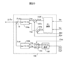
図20に、これまでの磁束推定器15,15Bに代わる起電圧推定器15Eの構成図を示す。実施例2以降の実施例において、磁束推定器の代わりに、起電圧推定器15Eを導入することで、実施例6となる。図20において、部品番号7f,153,154a,154b,156は、これまでの実施例における同じ番号のものと同一のものである。
FIG. 20 shows a configuration diagram of an
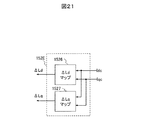
図20の起電圧推定器15Eでは、ΔL演算器152E、ならびに、乗算器157a,157b、が加えられている。ΔL演算器152Eでは、Idc、ならびにIqcに基づいて、各々の電流変化に対する磁束変化の傾きを演算する。これは、図16におけるdΦd/dI、ならびに、dΦq/dIqを求めていることになる(このような“傾き”に相当するインダクタンスを、一般には動的インダクタンスという)。この演算は、数式モデルを用いてもよいし、あるいは図21に示すように、電動機の磁場解析結果から、直接的にデータテーブルのマップ(ΔLdマップ1526,ΔLqマップ1527)を作成してもよい。
In the
dq軸間の干渉がある場合には、より複雑なモデルとなるが、いずれにしてもマップ化することは可能である。 If there is interference between the dq axes, it becomes a more complicated model, but it can be mapped anyway.
ΔL演算器152Eにて得られた動的インダクタンスと、検出した電流変化率を乗算器157a,157bにて掛け算することで、インダクタンス分の起電圧が演算できる。この起電圧は、線間電圧が狭いパルス状になる低速領域においては、インバータが印加しているパルス電圧に一致するはずである。こうして求めた起電圧から、その位相δdVeを演算する。
By multiplying the dynamic inductance obtained by the
一方で、インバータに実際に印加している電圧ベクトルも、ベクトル選択器156にて選択し、dq変換後に位相角δdVを求めておく。これらδdVとδdVeの偏差は、磁束の位置ずれによって生じるものであるから、このずれを零に制御することで、制御内部での磁束位置を実際の電動機の磁束位置に一致させることができる。
On the other hand, the voltage vector actually applied to the inverter is also selected by the
よって、実施例6においては、演算処理としては、テーブルの参照と、乗算を行うことで、極めて簡単な演算処理にて低速時の位置推定を行うことが可能となる。 Therefore, in the sixth embodiment, as a calculation process, it is possible to perform position estimation at a low speed by a very simple calculation process by referring to the table and performing multiplication.
次に図22を用いて、本発明の実施例7について説明する。 Next, Embodiment 7 of the present invention will be described with reference to FIG.
これまでの実施例では、電流変化率の検出サンプリングについてのみ説明を行ってきたが、電流値そのもののサンプリングに関しても、磁束位置の推定精度に大きな影響を与える。 In the embodiments so far, only the detection sampling of the current change rate has been described, but the sampling of the current value itself also greatly affects the estimation accuracy of the magnetic flux position.
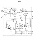
磁束推定、あるいは起電圧推定を行うには、電流変化率だけでなく、電流値そのものの情報が必要である。これと、電流変化率とはできる限り同時に検出するのが、推定精度を向上させる上でこのましい。図22は、それを具現化する制御器2Fを示したものである。
In order to perform magnetic flux estimation or electromotive voltage estimation, not only the current change rate but also information on the current value itself is required. It is preferable to detect this and the current change rate at the same time as much as possible in order to improve the estimation accuracy. FIG. 22 shows a
図22において、各々の部品は、これまでの実施例における同じ番号のものと同一のものである。図22は、実施例3である図11に最も近い構成となっている。図22では、サンプル/ホールド回路17bが、電流検出値Iu,Iwに対しても付加されており、サンプリングのタイミングは、トリガ発生器18の出力によって、電流変化率のサンプル/ホールドと同時に行われる。この結果、磁束推定器における演算では、同じ時刻にサンプリングされた電流、ならびに電流変化率が使用されることになる。すなわち、電流値と電流変化率の同時性が成立し、より高精度な推定演算が実現できるようになる。
In FIG. 22, each component is the same as that of the same number in the previous embodiments. FIG. 22 has a configuration closest to FIG. 11 which is the third embodiment. In FIG. 22, the sample /
次に図23を用いて、本発明の実施例8について説明する。
Next,
これまでの実施例では、電流/電流変化率検出器4に関しては、図2示したものを適用してきたが、その他のものでも電流変化率の検出が可能である。
In the embodiments so far, the current / current
図23は、コア材41、ホール素子42、アンプ43からなる通常の電流センサに対して、その端子部分の電圧測定機能を追加し、この電圧を持って電流変化率とする回路である。もともとの電流センサにはインダクタンス成分が存在するため、その端子電圧を利用すれば、電流の変化率を直接に検出することが可能となる。検出に必要な部品はアンプ46のみである。ただし、アンプ46は入力の信号を絶縁して出力する必要がある。しかしながら、図23の回路とすることで、コア材41に補助巻線を設ける必要はなくなる。
FIG. 23 is a circuit in which a voltage measuring function of the terminal portion is added to a normal current sensor composed of a
次に図24を用いて、本発明の実施例9について説明する。
Next,
図24は、通常の電流センサに対して直列にインダクタンスを接続し、その両端の起電圧から電流変化率を検出するものである。インダクタンス47は、端子電圧が自在に選べることになる。より高感度に電流変化率を検出するには、インダクタンスを別に取り付けた方がよい。このように、図24の回路構成とすることで、これまでの実施例の電流変化率検出感度を高く設定することが可能になる。
In FIG. 24, an inductance is connected in series to a normal current sensor, and the current change rate is detected from the electromotive voltage at both ends thereof. For the
次に図25を用いて、本発明の実施例10について説明する。
Next,
図25は、通常の電流センサに対して、微分演算器48を付加して電流変化率を演算するものである。微分演算を回路上で構成するのは困難であることはすでに述べた通りであるが、近年の半導体技術の進歩によって、高速AD変換や、ゲートアレイによる高速演算処理も可能である。大容量のモータドライブシステムであれば、センサコストが全体に占める割合も小さく、多少高級な演算器を導入することも可能である。例えば、測定器用として用いられている数十MHzのサンプリングが可能なADコンバータを用いて、デジタル部分を構成すれば、本実施例の実現は可能である。デジタル化によって、経年変化の影響が受けにくくなり、より信頼性の高い電流変化率検出が実現できるようになり、結果的には位置精度の高いセンサレス制御が実現可能となる。
FIG. 25 shows a current change rate calculated by adding a
次に図26、ならびに27を用いて、本発明の実施例11について説明する。
Next,
これまでの実施の形態では、電流変化率を直接検出器で検出することを前提としてきたが、アナログ回路の精度さえ確保できれば、2回のサンプリングによって、電流変化率を演算することも可能である。 In the embodiments so far, it has been assumed that the current change rate is directly detected by the detector. However, if the accuracy of the analog circuit can be ensured, the current change rate can be calculated by sampling twice. .
図26では、電流/電流変化率検出器4の代わりに、従来から用いられている電流検出器4Jが使用されている。その代わりに、サンプルホールド回路17を2個設けており、両者を、時間をずらしてサンプリングすることで、電流変化率を求めようというものである。
In FIG. 26, a
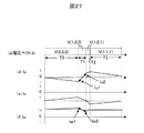
図26において、部品番号1、3〜17のブロックに関しては、これまでに示した同じ番号のものと同一のものである。本実施例の特徴部分は、トリガ発生器18Jから、2つのサンプルホールド信号が出力され、それぞれはサンプル/ホールド7a、ならびに7bに入力されている点である。これらの信号tr1,tr2によって、一つの電圧ベクトルにおいて、電流値を2回サンプリングする。その様子を図27に示す。図27において、電圧ベクトルV(1,0,0)の出力期間に2回の電流サンプルを行っている様子がわかる。この2つの電流検出値の差分から、電流変化率を演算によって求める。
In FIG. 26, the blocks of
このように、制御器内部に、電流変化率を演算する機能を設けてしまえば、外付けに電流変化率センサを取り付ける必要は全く不要になる。ただし、アナログ信号として、電流変化が十分大きな変化である必要がある。それには、大容量の電動機を駆動するシステム(例えば、鉄道車両)の方が適している。本来、キャリア周波数を上げられないことから、電流リプルは大きくなる傾向にあり、また、スイッチングロスを減らすためにも、キャリア周波数は下げる傾向にある。そのような用途であれば、より低コストにシステムをまとめる上で、本実施例が最適である。 Thus, if a function for calculating the current change rate is provided inside the controller, it is not necessary to attach an external current change rate sensor. However, the current change needs to be a sufficiently large change as an analog signal. For this purpose, a system (for example, a railway vehicle) that drives a large-capacity electric motor is more suitable. Originally, since the carrier frequency cannot be increased, the current ripple tends to increase, and the carrier frequency tends to decrease in order to reduce the switching loss. In such an application, the present embodiment is optimal for collecting the system at a lower cost.
次に図28を用いて、本発明の実施例12について説明する。
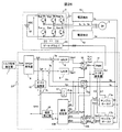
Next,
図28は、これまでの実施例である交流電動機駆動システムを鉄道車両に適用したものである。鉄道車両では、電動機の容量が100kW以上と大きく、キャリア周波数を高く設定できない。その上で、低速センサレス駆動を行うには、従来方式では高調波の印加が必須であった。本発明を適用することで、高調波印加を行うことなく、理想的なPWM波形のままで、交流電動機のセンサレス駆動が可能になる。 FIG. 28 shows the application of the AC motor drive system according to the embodiment so far to a railway vehicle. In a railway vehicle, the capacity of the electric motor is as large as 100 kW or more, and the carrier frequency cannot be set high. In addition, in order to perform low-speed sensorless driving, it has been essential to apply harmonics in the conventional method. By applying the present invention, sensorless driving of an AC motor can be performed with an ideal PWM waveform without applying harmonics.
以上、本発明による実施例について説明した。説明上、交流電動機として誘導機とPMモータを用いて説明したが、他の交流電動機、例えば、巻線型同期電動機、その他の交流電動機に対しても、すべての実施例が適用可能である。また、電流検出方法としては、三相の相電流のうち、二相のみを検出するものとしたが、三相すべてを検出しても全く問題ない。また、電流センサとして、直流母船電流をシャント抵抗器によって検出する手法も提案されているが、本発明も直流母線電流の検出値から変化率を求めて、位置推定を行うことは原理的には可能である。 The embodiment according to the present invention has been described above. For the sake of explanation, the induction motor and the PM motor are used as the AC motor. However, all the embodiments can be applied to other AC motors such as a wound synchronous motor and other AC motors. In addition, as a current detection method, only two phases of the three-phase currents are detected, but there is no problem even if all three phases are detected. Also, as a current sensor, a method of detecting a DC bus current using a shunt resistor has been proposed, but in the present invention, the rate of change is obtained from the detected value of the DC bus current to estimate the position in principle. Is possible.
尚、本発明における制御器は、マイコンで実現することが可能であり、説明に用いたそれぞれの部品は、マイコン内部のロジック、あるいはソフトウエアとして実現できるものである。 The controller in the present invention can be realized by a microcomputer, and each component used in the description can be realized as logic or software in the microcomputer.
既述の通り、本発明は交流電動機の回転位置、回転速度のセンサを用いることなく、零速度近傍での高精度駆動を実現する駆動装置の技術である。この装置の適用範囲は、低速にて高トルクを必要とする用途であり、電気鉄道、電気自動車を始め、産業用インバータ、それを用いた圧縮機、昇降機、コンベアなどの回転速度、トルク制御に利用可能である。 As described above, the present invention is a technology of a driving device that realizes high-precision driving near zero speed without using the rotational position and rotational speed sensors of the AC motor. The range of application of this equipment is for applications that require high torque at low speeds. For electric railways, electric vehicles, industrial inverters, compressors using them, elevators, conveyors, etc., for rotational speed and torque control. Is available.
1 トルク指令発生器
2,2B,2C,2D,2F 制御器
3 インバータ
4,4G,4H 電流及び電流変化率検出器
4J 電流検出器
5,5a,5b,5c,5d 三相誘導電動機
5C 永久磁石型動機電動機(PMモータ)
6 Id*,Iq*発生器
7a,7b,7c,7f,7g,7h 加減算器
8 d軸電流制御器(IdACR)
9 q軸電流制御器(IqACR)
10 dq逆変換器
11 PWM(パルス幅変調)発生器
12 すべり演算器
13 電気角位相演算器
14a,14b,14c dq変換器
15,15B,15E,15J 磁束推定器
16 速度推定器
17,17a,17b サンプル/ホールド
18,18J トリガ発生器
19 Δθe選択器
20 スイッチ
31 インバータ主回路
32 インバータ電源
33 ゲート・ドライバ
41 コア
42 ホール素子
43 アンプ
44 補助巻線
45 アンプ
46 アンプ
47 インダクタンス
48 微分演算器
151 磁束初期値演算器
152 磁束モデル演算器
152E ΔL演算器
153 dq変換器
154a,154b アークタンジェント演算器
155 フィルタ
161 比例積分制御器(PI制御器)
162 零発生器
1521a,1521b 抵抗設定器
1522a,1522b 積分器
1523a Idマップ
1523b Iqマップ
1524a,1524b 不完全微分器
1525a,1525b 遅れ要素
1526 ΔLdマップ
1527 ΔLqマップ
1
6 Id *, Iq *
9 q-axis current controller (IqACR)
10 dq
162
Claims (10)
前記インバータの線間電圧波形のPWMパルス列に対して、正側パルス列または負側パルス列の前後に極性の反転した微小パルスを波形の少なくとも一部分に設け、かつ、前記交流電動機の電流及び電流変化率を検出する手段を備え、前記電流の検出値及び前記電流変化率の検出値に基づいて前記交流電動機を制御することを特徴とする交流電動機の駆動装置。 An AC motor drive device having an inverter that converts direct current to alternating current, an AC motor connected to the inverter, and a controller that outputs a pulse width modulation signal to the inverter and controls the inverter,
For the PWM pulse train of the line voltage waveform of the inverter, a minute pulse whose polarity is reversed before and after the positive pulse train or the negative pulse train is provided in at least a part of the waveform, and the current and current change rate of the AC motor are set. A drive device for an AC motor, comprising: means for detecting, wherein the AC motor is controlled based on the detected value of the current and the detected value of the current change rate.
前記インバータの線間電圧波形は、交流出力の基本波周期360度に対して、180度期間を連続した正方向のパルス列とし、残りの180度期間を負方向のパルス列として前記交流電動機に電圧を印加し、かつ、前記交流電動機の電流及び電流変化率を検出する手段を備え、前記電流の検出値及び前記電流変化率の検出値に基づいて前記交流電動機を制御する交流電動機の駆動装置において、
前記インバータの出力するパルス列として、インバータのスイッチング状態が、三相すべてが同一とならない状態(三相すべての上アームがオン、あるいは三相すべての下アームオンでない状態)の2種類のスイッチング状態を連続して出力する期間を備えるものとし、該連続した2種類のスイッチング状態のうち、少なくとも一方のスイッチング状態において、前記電流変化率の検出を行い、該電流変化率の検出値に基づいて前記交流電動機の制御を行うことを特徴とする交流電動機の駆動装置。 An inverter for power conversion direct current to alternating current, and an AC motor connected to the inverter, and outputs a pulse width modulation signal to the inverter have a controller for controlling the inverter,
The line voltage waveform of the inverter is such that a 180-degree period is a continuous positive pulse train and the remaining 180-degree period is a negative pulse train with respect to a fundamental wave period of 360 degrees of AC output, and voltage is applied to the AC motor. In the drive device for an AC motor that includes the means for applying and detecting the current and the current change rate of the AC motor, and that controls the AC motor based on the detected value of the current and the detected value of the current change rate,
As the pulse train output by the inverter, the switching state of the inverter is continuous in two types of switching states where all three phases are not the same (the upper arm is not on for all three phases or the lower arm is not on for all three phases). The current change rate is detected in at least one of the two continuous switching states, and the AC motor is based on the detected value of the current change rate. The AC motor drive device is characterized in that the control is performed .
前記2種類連続して出力されるスイッチング状態において、それぞれの出力期間において、前記電流変化率の検出を行い、該2つの状態におけるそれぞれの電流変化率の検出値に基づいて前記交流電動機の制御を行うことを特徴とする交流電動機の駆動装置。 In the drive device of the alternating current motor according to claim 2 ,
In the two consecutive switching states, the current change rate is detected in each output period, and the AC motor is controlled based on the detected values of the current change rates in the two states. A drive device for an AC motor, characterized in that:
前記電流検出手段、ならびに前記電流変化率検出手段の検出値をサンプリングする際、すべてのサンプリングを、実質的に同時に行うように同一のトリガ信号によって行うことを特徴とする交流電動機の駆動装置。 In the alternating current motor drive device according to claim 1 or 2,
An AC motor drive device characterized in that when sampling the detection values of the current detection means and the current change rate detection means, all sampling is performed by the same trigger signal so as to be performed substantially simultaneously .
前記電流を検出する手段として、環状の磁性体コアに前記交流電動機の動力線を貫通させる構造のものを用いるものとし、該磁性体コアに補助巻線を設け、さらに該補助巻線の両端の電圧を検出する手段を備え、該電圧をもって電流変化率の検出値とすることを特徴とする交流電動機の駆動装置。 In the alternating current motor drive device according to claim 1 or 2 ,
As the means for detecting the current, one having a structure in which a power line of the AC motor is passed through an annular magnetic core, an auxiliary winding is provided in the magnetic core, and further, both ends of the auxiliary winding are provided. An AC motor drive device comprising means for detecting a voltage and using the voltage as a detected value of a current change rate .
前記電流変化率を検出する手段として、前記交流電動機の電流検出手段の両端の電圧を検出する手段を設け、該電圧をもって電流変化率の検出値とすることを特徴とする交流電動機の駆動装置。 In the alternating current motor drive device according to claim 1 or 2 ,
An AC motor drive apparatus comprising: a means for detecting a voltage at both ends of the current detection means of the AC motor as the means for detecting the current change rate, and using the voltage as a detected value of the current change rate .
前記電流変化率を検出する手段として、前記交流電動機に直列にインダクタンスを接続し、該インダクタンスの両端の電圧を検出する手段を設け、該電圧をもって電流変化率の検出値とすることを特徴とする交流電動機の駆動装置。 In the alternating current motor drive device according to claim 1 or 2 ,
As means for detecting the current change rate, an inductance is connected in series to the AC motor, and means for detecting a voltage at both ends of the inductance is provided, and the voltage is used as a detected value of the current change rate. AC motor drive device.
前記電流及び電流変化率を検出する手段に代えて、電流を検出する手段を備えるようにするとともに、前記電流変化率を、前記電流を検出する手段の出力に対して、アナログ回路、もしくはアナログとデジタル混在の回路による信号処理を行うことによって得ることを特徴とする交流電動機の駆動装置。 In the alternating current motor drive device according to claim 1 or 2,
Instead of means for detecting the current and the current change rate, as well as to comprise means for detecting a current, the current change rate, the output of the means for detecting the pre-SL current, analog circuitry or, driving an AC motor, wherein the resulting isosamples due to performing signal processing by the circuit of the analog and digital mixed.
前記電流及び電流変化率を検出する手段に代えて、電流を検出する手段を備えるようにするとともに、前記電流変化率を、前記インバータのスイッチング状態が同一である期間(PWMパルスが変化していない期間)において、前記電流を検出する手段により電流値を複数回サンプリングし、該サンプリング値に基づいて得ることを特徴とする交流電動機の駆動装置。 In the alternating current motor drive device according to claim 1 or 2,
In place of the means for detecting the current and the current change rate, a means for detecting the current is provided, and the current change rate is set for a period in which the switching state of the inverter is the same (the PWM pulse has not changed). In a period), the current value is sampled a plurality of times by means for detecting the current, and obtained based on the sampled value.
Priority Applications (4)
| Application Number | Priority Date | Filing Date | Title |
|---|---|---|---|
| JP2010040219A JP5116785B2 (en) | 2010-02-25 | 2010-02-25 | AC motor drive device and motor vehicle |
| CN201110042092.6A CN102170261B (en) | 2010-02-25 | 2011-02-17 | Drive device for an alternating current motor and an electric motor vehicle |
| US13/030,168 US8674647B2 (en) | 2010-02-25 | 2011-02-18 | Drive device for alternating current motor and electric motor vehicle |
| EP11250193.7A EP2362538A3 (en) | 2010-02-25 | 2011-02-18 | Drive device for an alternating current motor and an electric motor vehicle |
Applications Claiming Priority (1)
| Application Number | Priority Date | Filing Date | Title |
|---|---|---|---|
| JP2010040219A JP5116785B2 (en) | 2010-02-25 | 2010-02-25 | AC motor drive device and motor vehicle |
Publications (2)
| Publication Number | Publication Date |
|---|---|
| JP2011176975A JP2011176975A (en) | 2011-09-08 |
| JP5116785B2 true JP5116785B2 (en) | 2013-01-09 |
Family
ID=44115580
Family Applications (1)
| Application Number | Title | Priority Date | Filing Date |
|---|---|---|---|
| JP2010040219A Expired - Fee Related JP5116785B2 (en) | 2010-02-25 | 2010-02-25 | AC motor drive device and motor vehicle |
Country Status (4)
| Country | Link |
|---|---|
| US (1) | US8674647B2 (en) |
| EP (1) | EP2362538A3 (en) |
| JP (1) | JP5116785B2 (en) |
| CN (1) | CN102170261B (en) |
Families Citing this family (38)
| Publication number | Priority date | Publication date | Assignee | Title |
|---|---|---|---|---|
| JP5396876B2 (en) * | 2009-01-21 | 2014-01-22 | 株式会社安川電機 | AC motor control device |
| JP5446627B2 (en) * | 2009-09-08 | 2014-03-19 | 株式会社安川電機 | Elevator control device and control method thereof |
| KR101549283B1 (en) | 2011-10-12 | 2015-09-01 | 엘에스산전 주식회사 | Parameter estimating apparatus for permanent magnet synchronous motor driving system |
| US9088238B2 (en) * | 2012-03-06 | 2015-07-21 | Dyson Technology Limited | Method of determining the rotor position of a permanent-magnet motor |
| US9318989B2 (en) * | 2012-03-22 | 2016-04-19 | Nissan Motor Co., Ltd. | Three-phase AC induction motor control device and three-phase AC induction motor control method |
| CN102694498B (en) * | 2012-05-31 | 2015-02-25 | 湖南南车时代电动汽车股份有限公司 | Device and method for resisting rotor disturbance of permanent-magnet synchronous motor in zero-speed or extremely-low-speed state |
| CN102710205B (en) * | 2012-06-13 | 2016-05-25 | 深圳市汇川技术股份有限公司 | The directed control system of asynchronous machine and method |
| FR2994355B1 (en) * | 2012-08-06 | 2014-08-29 | Renault Sa | SYSTEM FOR CONTROLLING THE ELECTROMAGNETIC TORQUE OF AN ELECTRIC MACHINE, IN PARTICULAR FOR A MOTOR VEHICLE |
| GB2505189B (en) * | 2012-08-20 | 2020-01-15 | Nidec Control Techniques Ltd | Modulation of switching signals in power converters |
| WO2014115626A1 (en) * | 2013-01-25 | 2014-07-31 | 日産自動車株式会社 | Induction motor control device and induction motor control method |
| KR101759371B1 (en) | 2013-04-04 | 2017-07-18 | 엘에스산전 주식회사 | Sensorless vector control apparatus for induction motor |
| WO2015015597A1 (en) * | 2013-07-31 | 2015-02-05 | 株式会社日立製作所 | Motor control device |
| TWI499193B (en) * | 2013-08-16 | 2015-09-01 | Univ Nat Cheng Kung | Power conversion apparatus and control method thereof |
| JP6429453B2 (en) * | 2013-11-26 | 2018-11-28 | キヤノン株式会社 | Motor control apparatus and image forming apparatus |
| US9419553B2 (en) * | 2014-07-25 | 2016-08-16 | Denso Corporation | Apparatus for controlling rotary machine |
| KR101535036B1 (en) * | 2014-08-25 | 2015-07-24 | 현대자동차주식회사 | Apparatus and Method for compensating torque about current order of driving motor |
| US10483892B2 (en) * | 2014-08-29 | 2019-11-19 | Nissan Motor Co., Ltd. | Variable magnetization machine controller |
| CN104467606A (en) * | 2014-12-12 | 2015-03-25 | 广西科技大学 | Asynchronous motor electric controller applied to car |
| CN104539216A (en) * | 2014-12-12 | 2015-04-22 | 广西科技大学 | Asynchronous motor electric vehicle control device |
| CN104467608A (en) * | 2014-12-12 | 2015-03-25 | 广西科技大学 | Asynchronous motor electric-vehicle control system |
| US9509240B2 (en) * | 2014-12-30 | 2016-11-29 | Tesla Motors, Inc. | Electric motor using multiple reference frames for flux angle |
| US9780711B2 (en) | 2015-02-03 | 2017-10-03 | Mitsubishi Electric Research Laboratories, Inc. | Method and system for controlling an angualr speed of an induction motor |
| US9831812B2 (en) * | 2015-02-27 | 2017-11-28 | Nutech Ventures | Direct torque control of AC electric machines |
| DE102015205691A1 (en) * | 2015-03-30 | 2016-10-06 | Siemens Aktiengesellschaft | Method for reducing the noise of an electric motor |
| GB2545023B (en) * | 2015-12-04 | 2018-06-06 | General Electric Technology Gmbh | Improvements in or relating to converters |
| US9985563B2 (en) | 2016-01-11 | 2018-05-29 | Mitsubishi Electric Research Laboratories, Inc. | Method and system for controlling angular speeds of motors in speed sensorless induction motors |
| US9966891B2 (en) | 2016-03-16 | 2018-05-08 | Mitsubishi Electric Research Laboratories, Inc. | System and method for controlling speed of electric motor |
| US9673743B1 (en) | 2016-09-08 | 2017-06-06 | Limiter Power Management System (PTY) LTD. | Efficient motor control |
| JP6334017B1 (en) * | 2017-01-25 | 2018-05-30 | ファナック株式会社 | Induction motor control device |
| DE112017007953T5 (en) * | 2017-10-24 | 2020-07-30 | Mitsubishi Electric Corporation | ANOMALY DIAGNOSTIC DEVICE, ANOMALY DIAGNOSTIC PROCEDURE, AND ANOMALY DIAGNOSTIC SYSTEM |
| CN107933935B (en) * | 2017-11-29 | 2024-02-23 | 深圳市科比特航空科技有限公司 | Unmanned aerial vehicle control system |
| GB201813335D0 (en) * | 2018-08-15 | 2018-09-26 | Technelec Ltd | Flux linkage to current observer for synchronous machines |
| KR20210016234A (en) * | 2019-08-02 | 2021-02-15 | 현대자동차주식회사 | Device for detecting current leakage and current leakage detection system including the same |
| TWI723605B (en) * | 2019-10-31 | 2021-04-01 | 國立中央大學 | Motor control system and control method of maximum power factor controller thereof |
| JP7362523B2 (en) * | 2020-03-17 | 2023-10-17 | 日立Astemo株式会社 | Synchronous machine control device, synchronous machine control method, and electric vehicle |
| JP7492445B2 (en) | 2020-11-27 | 2024-05-29 | オリエンタルモーター株式会社 | Motor Control Device |
| GB2623245A (en) * | 2021-07-28 | 2024-04-10 | Tianjin Saixiang Tech Co Ltd | Adaptive current control method and system for alternating current servo motor |
| CN116404941B (en) * | 2023-06-08 | 2024-02-13 | 宁德时代新能源科技股份有限公司 | Motor control method and device and readable storage medium |
Family Cites Families (21)
| Publication number | Priority date | Publication date | Assignee | Title |
|---|---|---|---|---|
| IT1241678B (en) | 1990-03-01 | 1994-01-31 | Omb Sas Di Rebecchi Dante & C | PRESSING AND SELECTING MACHINE FOR SOLID, METALLIC, FERROUS AND OTHER WASTE, AS CONTAINERS, BOTTLES AND SIMILAR TINS |
| US5015939A (en) * | 1990-08-10 | 1991-05-14 | Synektron Corporation | Control circuit for switched reluctance motor |
| KR920010163B1 (en) * | 1990-12-18 | 1992-11-19 | 삼성전자 주식회사 | Frequency control method and device for air conditioner compressor |
| US5097190A (en) * | 1991-02-11 | 1992-03-17 | General Electric Company | Rotor position estimator for a switched reluctance machine |
| ZA949795B (en) * | 1993-12-17 | 1995-08-18 | Hitachi Ltd | Electric power conversion equipment. |
| JP3312520B2 (en) | 1995-01-24 | 2002-08-12 | 富士電機株式会社 | Magnetic pole position detection device for motor |
| US6172498B1 (en) * | 1998-09-29 | 2001-01-09 | Rockwell Technologies, Llc | Method and apparatus for rotor angle detection |
| JP2001169560A (en) | 1999-12-02 | 2001-06-22 | Mitsubishi Electric Corp | Power converter |
| JP4596092B2 (en) | 2000-03-31 | 2010-12-08 | 株式会社安川電機 | Induction motor magnetic flux position estimation method and control apparatus |
| JP2002078391A (en) * | 2000-08-30 | 2002-03-15 | Hitachi Ltd | Drive system of ac motor |
| JP4687846B2 (en) | 2001-03-26 | 2011-05-25 | 株式会社安川電機 | Magnetic pole position estimation method and control apparatus for synchronous motor |
| JP3661642B2 (en) * | 2001-12-27 | 2005-06-15 | 株式会社日立製作所 | Motor control device and control method thereof |
| US7412339B2 (en) * | 2002-05-24 | 2008-08-12 | Virginia Tech Intellectual Properties, Inc. | Method and apparatus for identifying an operational phase of a motor phase winding and controlling energization of the phase winding |
| JP4581544B2 (en) * | 2004-08-02 | 2010-11-17 | 国産電機株式会社 | Rotor electric machine rotor position determination method, rotor position determination device, and rotary electric machine control device |
| JP4455981B2 (en) * | 2004-11-30 | 2010-04-21 | 株式会社日立産機システム | Synchronous motor drive device |
| JP2006230169A (en) * | 2005-02-21 | 2006-08-31 | Toshiba Corp | Controller for synchronous machine |
| US7477034B2 (en) * | 2005-09-29 | 2009-01-13 | Agile Systems Inc. | System and method for commutating a motor using back electromotive force signals |
| JP4657892B2 (en) * | 2005-11-04 | 2011-03-23 | 本田技研工業株式会社 | Rotor angle estimation device and rotor angle estimation method for DC brushless motor |
| JP4749874B2 (en) * | 2006-01-30 | 2011-08-17 | 日立オートモティブシステムズ株式会社 | Power conversion device and motor drive device using the same |
| JP5011815B2 (en) * | 2006-05-15 | 2012-08-29 | パナソニック株式会社 | Brushless DC motor control device and ventilation blower equipped with the same |
| JP2007336641A (en) * | 2006-06-13 | 2007-12-27 | Denso Corp | Position sensorless driving device for synchronous motor |
-
2010
- 2010-02-25 JP JP2010040219A patent/JP5116785B2/en not_active Expired - Fee Related
-
2011
- 2011-02-17 CN CN201110042092.6A patent/CN102170261B/en not_active Expired - Fee Related
- 2011-02-18 EP EP11250193.7A patent/EP2362538A3/en not_active Withdrawn
- 2011-02-18 US US13/030,168 patent/US8674647B2/en active Active
Also Published As
| Publication number | Publication date |
|---|---|
| EP2362538A3 (en) | 2016-02-17 |
| US20110204831A1 (en) | 2011-08-25 |
| EP2362538A2 (en) | 2011-08-31 |
| US8674647B2 (en) | 2014-03-18 |
| CN102170261A (en) | 2011-08-31 |
| JP2011176975A (en) | 2011-09-08 |
| CN102170261B (en) | 2014-01-08 |
Similar Documents
| Publication | Publication Date | Title |
|---|---|---|
| JP5116785B2 (en) | AC motor drive device and motor vehicle | |
| US7772789B2 (en) | Motor controller | |
| JP5150585B2 (en) | Permanent magnet synchronous motor drive device | |
| JP5324159B2 (en) | Motor control device | |
| US7045988B2 (en) | Sensorless controller of AC motor and control method | |
| JP3411878B2 (en) | Method for estimating rotor position of synchronous motor, control method without position sensor, and control device | |
| JP4928855B2 (en) | Sensorless control device for synchronous machine | |
| CN1741367B (en) | Position-sensorless control circuit | |
| JP2008086129A (en) | Ac motor controller and constant measurement apparatus | |
| JP2007110837A (en) | Method for estimating magnetic pole position and motor controller | |
| JPH0951700A (en) | Controlling device of rotary electric machine | |
| EP2120324A1 (en) | Synchronous motor sensorless control device | |
| JP6015486B2 (en) | Variable speed controller for synchronous motor | |
| EP3252942A1 (en) | Inverter control device and motor drive system | |
| JP2009268268A (en) | Motor controller and generator controller | |
| JP6536473B2 (en) | Control device of rotating electric machine | |
| JP5120621B2 (en) | Control device for permanent magnet type synchronous motor | |
| Zhao | Position/speed sensorless control for permanent-magnet synchronous machines | |
| JP2008206330A (en) | Device and method for estimating magnetic pole position of synchronous electric motor | |
| JP2014117069A (en) | Control apparatus for ac rotary machine and control method for ac rotary machine | |
| JP2002272195A (en) | Synchronous motor control device | |
| JP2011239518A (en) | Method and apparatus for estimating position and speed of rotor of stepping motor | |
| CN107615641B (en) | Power conversion device, secondary time constant measurement method, and speed control method for induction motor | |
| JP2007267547A (en) | Motor controller | |
| JP4061446B2 (en) | Resistance value identification method and control device for synchronous motor |
Legal Events
| Date | Code | Title | Description |
|---|---|---|---|
| A621 | Written request for application examination |
Free format text: JAPANESE INTERMEDIATE CODE: A621 Effective date: 20111128 |
|
| A977 | Report on retrieval |
Free format text: JAPANESE INTERMEDIATE CODE: A971007 Effective date: 20120413 |
|
| A131 | Notification of reasons for refusal |
Free format text: JAPANESE INTERMEDIATE CODE: A131 Effective date: 20120424 |
|
| A521 | Request for written amendment filed |
Free format text: JAPANESE INTERMEDIATE CODE: A523 Effective date: 20120625 |
|
| A131 | Notification of reasons for refusal |
Free format text: JAPANESE INTERMEDIATE CODE: A131 Effective date: 20120731 |
|
| A521 | Request for written amendment filed |
Free format text: JAPANESE INTERMEDIATE CODE: A523 Effective date: 20120906 |
|
| TRDD | Decision of grant or rejection written | ||
| A01 | Written decision to grant a patent or to grant a registration (utility model) |
Free format text: JAPANESE INTERMEDIATE CODE: A01 Effective date: 20121002 |
|
| A01 | Written decision to grant a patent or to grant a registration (utility model) |
Free format text: JAPANESE INTERMEDIATE CODE: A01 |
|
| A61 | First payment of annual fees (during grant procedure) |
Free format text: JAPANESE INTERMEDIATE CODE: A61 Effective date: 20121016 |
|
| R150 | Certificate of patent or registration of utility model |
Ref document number: 5116785 Country of ref document: JP Free format text: JAPANESE INTERMEDIATE CODE: R150 Free format text: JAPANESE INTERMEDIATE CODE: R150 |
|
| FPAY | Renewal fee payment (event date is renewal date of database) |
Free format text: PAYMENT UNTIL: 20151026 Year of fee payment: 3 |
|
| LAPS | Cancellation because of no payment of annual fees |
