JP5115895B2 - Threading device - Google Patents
Threading device Download PDFInfo
- Publication number
- JP5115895B2 JP5115895B2 JP2011503935A JP2011503935A JP5115895B2 JP 5115895 B2 JP5115895 B2 JP 5115895B2 JP 2011503935 A JP2011503935 A JP 2011503935A JP 2011503935 A JP2011503935 A JP 2011503935A JP 5115895 B2 JP5115895 B2 JP 5115895B2
- Authority
- JP
- Japan
- Prior art keywords
- threading device
- toothed
- threading
- leash
- handle
- Prior art date
- Legal status (The legal status is an assumption and is not a legal conclusion. Google has not performed a legal analysis and makes no representation as to the accuracy of the status listed.)
- Active
Links
- 230000009471 action Effects 0.000 description 15
- 125000006850 spacer group Chemical group 0.000 description 8
- 230000006872 improvement Effects 0.000 description 6
- 239000000463 material Substances 0.000 description 5
- 239000004952 Polyamide Substances 0.000 description 4
- 230000008901 benefit Effects 0.000 description 4
- 230000005540 biological transmission Effects 0.000 description 4
- 229920002647 polyamide Polymers 0.000 description 4
- XLYOFNOQVPJJNP-UHFFFAOYSA-N water Substances O XLYOFNOQVPJJNP-UHFFFAOYSA-N 0.000 description 4
- 239000000835 fiber Substances 0.000 description 3
- 238000003754 machining Methods 0.000 description 3
- 238000005058 metal casting Methods 0.000 description 3
- 238000000034 method Methods 0.000 description 3
- 239000002990 reinforced plastic Substances 0.000 description 3
- 241000242583 Scyphozoa Species 0.000 description 2
- 238000005266 casting Methods 0.000 description 2
- 230000006835 compression Effects 0.000 description 2
- 238000007906 compression Methods 0.000 description 2
- 239000002783 friction material Substances 0.000 description 2
- 229910001220 stainless steel Inorganic materials 0.000 description 2
- 239000010935 stainless steel Substances 0.000 description 2
- 239000000126 substance Substances 0.000 description 2
- 229930182556 Polyacetal Natural products 0.000 description 1
- 238000005452 bending Methods 0.000 description 1
- 230000001419 dependent effect Effects 0.000 description 1
- 238000012986 modification Methods 0.000 description 1
- 230000004048 modification Effects 0.000 description 1
- 230000009972 noncorrosive effect Effects 0.000 description 1
- 239000004033 plastic Substances 0.000 description 1
- 229920003023 plastic Polymers 0.000 description 1
- 229920006324 polyoxymethylene Polymers 0.000 description 1
- 238000003825 pressing Methods 0.000 description 1
- 239000011435 rock Substances 0.000 description 1
- 229920001169 thermoplastic Polymers 0.000 description 1
- 239000004416 thermosoftening plastic Substances 0.000 description 1
Images


Classifications
-
- B—PERFORMING OPERATIONS; TRANSPORTING
- B63—SHIPS OR OTHER WATERBORNE VESSELS; RELATED EQUIPMENT
- B63B—SHIPS OR OTHER WATERBORNE VESSELS; EQUIPMENT FOR SHIPPING
- B63B21/00—Tying-up; Shifting, towing, or pushing equipment; Anchoring
- B63B21/54—Boat-hooks or the like, e.g. hooks detachably mounted to a pole
Landscapes
- Chemical & Material Sciences (AREA)
- Engineering & Computer Science (AREA)
- Combustion & Propulsion (AREA)
- Mechanical Engineering (AREA)
- Ocean & Marine Engineering (AREA)
- Transmission Devices (AREA)
- Emergency Lowering Means (AREA)
- Pulleys (AREA)
Description
この発明は、ブイ上または岸の固定位置に取り付けられた係船リングを通して、ボートの係船索を通すなどの、開口に綱を通すための通し装置に関する。本通し装置の一つの利点は、通し操作が離れた位置から実施することができることである。 The present invention relates to a threading device for passing a rope through an opening, such as passing a mooring line of a boat through a mooring ring mounted on a fixed position on a buoy or on a shore. One advantage of the threading device is that the threading operation can be performed from a remote location.
様々な寸法のレジャーボートに関する問題の一つは、ボートを一つ以上の係船ブイ、および/または一つ以上の係船リングへ繋ぐことである。係船リングは、ボートの本拠地である港の岸壁または浮桟橋に取り付けられる。係船リングは自然港の岩などにも取付けられる。 One problem with various sized leisure boats is connecting the boat to one or more mooring buoys and / or one or more mooring rings. The mooring ring is attached to the quay or floating pier of the port where the boat is based. The mooring ring can also be attached to rocks in natural harbors.
ボートで上陸する場合の問題は、もし係船リング自身に結び目を作ることを回避したい場合、係船索または係留綱を係船リングへ通さなければならないことである。係船リングは、しばしばボートおよび綱をリングに通す人から離れた場所にある。一例として、例えばもしボートが比較的大型の船舶であれば、人は係船ブイより高い位置にいる。この場合、人はレールを拡張しなければならない。別の例では、リングが自然港の岩礁または断崖に取り付けられる。断崖は急峻であり、および/または滑りやすく、そのためリングに到達するための人の上陸は困難であり、または危険でさえある。もしボートの喫水と水深がボートの上陸を妨げるならば、上陸は不可能でさえある。 The problem with landing on a boat is that if you want to avoid knotting the mooring ring itself, you must pass a mooring line or mooring line through the mooring ring. Mooring rings are often remote from those who pass boats and leash through the ring. As an example, if the boat is a relatively large vessel, for example, the person is higher than the mooring buoy. In this case, one has to extend the rail. In another example, the ring is attached to a natural harbor reef or cliff. The cliffs are steep and / or slippery, so it is difficult or even dangerous for people to land to reach the ring. If the draft and depth of the boat prevent the boat from landing, landing is not possible.
ボートの係船の問題は、レジャーボートの数の増加のため、又平均的なボート寸法の増加のため増加しつつある。ボートがより大型になる程、係船リングへの到着がより困難になる。今日のボート所有者には、特により大型のボートの場合、ボートを操縦したり、取り扱ったりする経験が少ない人がいるので、問題は更に増加する。 Boat mooring problems are increasing due to an increase in the number of leisure boats and an increase in average boat size. The larger the boat, the more difficult it is to reach the mooring ring. The problem is further compounded by today's boat owners, especially in the case of larger boats, because there are few people who have less experience maneuvering and handling the boat.
人がリング等の開口に綱を通すことを助けるため、様々な装置が提案されてきた。 Various devices have been proposed to help a person pass a rope through an opening such as a ring.
米国No4,560,098は、綱をリング部材等に通すのに適した装置に関する。通し装置は、本体部、その周辺に凹部を有する、少なくとも1つの車輪からなるロータ部、および車輪と連携する通し部材からなる。この方式は、ある場合は機能するが、所定方向での通し作用に適する。車輪は特定の開始位置にバイアスされる。本装置は,それが作用するリング部材と綱の寸法に関してやや制限もある。車輪を回転させる力は直接車輪に加えられるので、レバーアームがやや短いため、確保できるトルクに制限がある。通し部材は、構造をやや弱くする車輪上で、浮遊して吊り下げられる。本装置は通常のボートフックとしては使用することができない。 U.S. Pat. No. 4,560,098 relates to a device suitable for threading a rope through a ring member or the like. The threading device includes a main body part, a rotor part having at least one wheel having a recess in the periphery thereof, and a threading member that cooperates with the wheel. This method works in some cases, but is suitable for threading in a predetermined direction. The wheels are biased to a specific starting position. The device is also somewhat limited with respect to the dimensions of the ring member and rope that it operates on. Since the force for rotating the wheel is directly applied to the wheel, the lever arm is somewhat short, so there is a limit to the torque that can be secured. The threading member is suspended and suspended on wheels that weaken the structure somewhat. This device cannot be used as a normal boat hook.
独逸No10‐2006‐029810A1で、リング部材等へ綱を通すための別の装置が示される。この装置は綱用の孔とリング部材に適合した凹部を有する、一方向に回転可能な車輪からなる。本装置は、車輪を回転させる力は直接車輪に加えられるので、綱をリング部材へ通すため、2つの異なる方向へ動かさなければならない。レバーアームがやや短いので、このように確保できるトルクは、やや制限される。第1の移動は、引く方向の移動を使って通しを終了する前に、下向きに押す方向の移動がなければならない。通しを逆にすることはできない。通しは、ユーザにやや高精度を要求するので、これは移動するボートから達成することは困難である。本装置は、それが作用するリング部材と綱の寸法に関して、やや制限される。本装置は通し操作中、通常のボートフックとして使用することはできない。 In German No. 10-2006-029810A1, another device for threading a rope through a ring member or the like is shown. The device consists of a wheel that is rotatable in one direction with a hole for the rope and a recess adapted to the ring member. The device must be moved in two different directions in order to pass the rope through the ring member because the force that rotates the wheel is applied directly to the wheel. Since the lever arm is slightly short, the torque that can be secured in this way is somewhat limited. The first movement must be a downward pushing movement before using the pull movement to end the threading. The thread cannot be reversed. This is difficult to achieve from a moving boat as it requires a little higher accuracy from the user. The device is somewhat limited with respect to the dimensions of the ring member and the rope on which it operates. This device cannot be used as a normal boat hook during threading operation.
英国No287,407および英国No442,857は、通し装置の更に2つの例を示す。両方共やや複雑であり、特定のループした綱端が機能することを必要とする。両方共、使用前に特定の始動位置へ手動で移動させなければならず、両方共一方向のみで使用することができる。両装置共、通常のボートフックとしての使用には適していない。 UK No. 287,407 and UK No. 442,857 show two more examples of threading devices. Both are somewhat complex and require specific looped rope ends to function. Both must be manually moved to a specific starting position before use, and both can be used in only one direction. Neither device is suitable for use as a normal boat hook.
既知の通し装置は、全て何らかの欠点がある。このように、通し装置には改善の余地がある。 All known threading devices have some drawbacks. Thus, there is room for improvement in the threading device.
従って、本発明の目的は、リング部材を通して、または目標物の周りに綱を通すための改良された通し装置を提供することである。本発明の別の目的は、通しサイクルに対してのみ一方向の操作を必要とする、改良された通し装置を提供することである。本発明の更なる目的は、押し作用または引き作用のいずれかで、綱を通すことができる、改良された通し装置を提供することである。 Accordingly, it is an object of the present invention to provide an improved threading device for threading a rope through a ring member or around a target. Another object of the present invention is to provide an improved threading device that requires one-way operation only for the threading cycle. It is a further object of the present invention to provide an improved threading device that is capable of threading a rope in either a pushing or pulling action.
弓型要素は、開口が第1の方向を向く第1の位置と、開口が第2の方向を向く第2の位置とをとるように適合され、本体と、本体内に吊り下げられ、開口を有する回転可能な弓型要素と、弓型要素上をスライドするように配置された綱保持手段と、を備える、リング部材等を通して綱を通すための通し装置で、通し装置は、更に、第1の位置と第2の位置の間で弓型要素を回転させるため、弓型要素が外面へ動くように適合された移動手段を備えることで、本発明の目的は達成される。 The arcuate element is adapted to assume a first position in which the opening faces in a first direction and a second position in which the opening faces in a second direction, and is suspended from the body and the body. A threading device for threading a rope through a ring member or the like, the threading device further comprising: a rotatable arcuate element having a looping element, and a rope holding means arranged to slide on the arcuate element; The object of the present invention is achieved by providing moving means adapted to move the arcuate element to the outer surface for rotating the arcuate element between the first position and the second position.
本発明による通し装置の、この第1の実施例により、リング部材から離れて操作が可能であり、かつ外側の動きは弓型要素の方へ行われるので、弓型要素を自由に回転させる通し装置が得られる。外側の動きは、リング部材と弓型要素の間の接触面の位置に関係なく、弓型要素を回転させる。このように、通し装置は弓型要素の回転のための特定トルクレバーに依存しない。 With this first embodiment of the threading device according to the invention, it is possible to operate away from the ring member and the outward movement is towards the arcuate element, so that the threading element freely rotates. A device is obtained. The outward movement rotates the arcuate element regardless of the position of the contact surface between the ring member and the arcuate element. In this way, the threading device does not rely on a specific torque lever for the rotation of the arcuate element.
本発明による通し装置の有利な更なる改良点で、弓型要素の方への動きは、長手方向で、移動手段はビームである。このようにして、例えばハンドルから引く移動を使って弓型要素を回転させ、これにより綱を通すことができる。このようにして使用が容易な通し装置が生み出される。 In a further advantageous refinement of the threading device according to the invention, the movement towards the arcuate element is longitudinal and the moving means is a beam. In this way, the bow element can be rotated, for example using a movement pulled from the handle, and thereby threaded. In this way, a threading device that is easy to use is created.
本発明による通し装置の有利な更なる改良点で、弓型要素は、その外面上に複数の歯を備える。ビームは複数の歯も備える。これにより、弓型要素の方へのスリップのない動きが生ずる。このように開始位置と最終位置は同じ位置である。 In an advantageous further improvement of the threading device according to the invention, the arcuate element comprises a plurality of teeth on its outer surface. The beam also includes a plurality of teeth. This results in a slip-free movement towards the bow element. Thus, the start position and the final position are the same position.
本発明による通し装置の有利な更なる改良点で、通し装置は、更に弓型要素へラックを移動させるように適合された複数の歯付き車輪を備える。別の改良点で、歯付きベルトを使用して移動を行う。この利点は、弓型要素の開口が歯付き車輪を通過しても、弓型要素を回転させることができる堅牢な通し装置が得られることである。 In a further advantageous refinement of the threading device according to the invention, the threading device further comprises a plurality of toothed wheels adapted to move the rack to the arcuate element. Another improvement is to use a toothed belt for movement. The advantage is that a robust threading device is obtained that can rotate the arcuate element even if the arcuate element opening passes through the toothed wheel.
本発明による通し装置の有利な更なる改良点で、ハンドルの引きまたは押しにより、動きが達成される。これにより、外のレバー等を操作する必要がないので、通し装置の容易で簡単な操作が可能になる。 In a further advantageous refinement of the threading device according to the invention, movement is achieved by pulling or pushing the handle. Thereby, since it is not necessary to operate an outer lever etc., an easy and simple operation of the threading device becomes possible.
本発明による通し装置の有利な更なる改良点で、綱保持手段は、弓型要素の開口を超えて回転するように適合される。このようにして簡単な通し装置が提供される。 In a further advantageous refinement of the threading device according to the invention, the rope holding means is adapted to rotate beyond the opening of the arcuate element. A simple threading device is thus provided.
本発明は、付属図面で示される実施例を参照して、以下でより詳細に記述される。 The invention will be described in more detail below with reference to embodiments shown in the accompanying drawings.
以下に記載される、更なる改良点を有する本発明の実施例は、単なる例と見なすべきで、特許請求による保護範囲を限定するものではない。例において、係船リングは綱が処理される例として使用される。本発明の通し装置は、適切な開口を通して、またはポール等の周りで、またはロープの周りでも、綱、ロープまたは針金やケーブルでも通すのにも適していると理解されるべきである。本装置は、例えば防水シート等を吊り下げる場合などの、海上での用途以外の他の目的のための綱またはロープを通すためにも使用される。 The embodiments of the invention with further improvements described below are to be regarded merely as examples and are not intended to limit the scope of protection according to the claims. In the example, the mooring ring is used as an example where the leash is processed. It should be understood that the threading device of the present invention is also suitable for threading a rope, rope or wire or cable through a suitable opening or around a pole or the like or around a rope. The device is also used to thread ropes or ropes for other purposes other than marine applications, such as when hanging tarpaulins or the like.
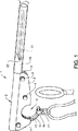
図1、図2は本発明の通し装置の第1の実施例を示す。通し装置1は、第1の側壁3と、第2の側壁4を有する本体部2を備える。第1の側壁3と第2の側壁4は平行であり、所定距離を隔てて設置される。側壁は多数のスペーサにより所定位置に保持される。各スペーサは、例えば皿頭または平坦な頭を有するボルトまたはネジにより、本体へ取り付けられる。表示される例において、第1のボルト5、第2のボルト6および第3のボルト7は、対応するスペーサと共に使用される。各スペーサ上には、車輪が回転可能に吊り下げられる。第1のボルト5のスペーサ上に、第1の車輪8が吊り下げられ、第2のボルト6のスペーサ上に、第2の車輪9が吊り下げられ、および第3のボルト7のスペーサ上に、第3の車輪10が吊り下げられる。車輪は自由に回転することが可能であり、好ましくは例えばポリアミドやポリアセタールなどの熱可塑性があり、低摩擦の材料から作られる。
1 and 2 show a first embodiment of the threading device of the present invention. The threading device 1 includes a
ベルト11は車輪上を走る。ベルトは、ビーム18の弓型要素14の方への長手方向移動に適合される。この動きは、好ましくはベルトが、ビーム上または弓型要素上のいずれかで、スリップしない、または滑らないように、高摩擦下で行われる。この例で、ベルトはスリップを防止するため、歯(28)を備えるが、スリップを防止するための他の手段も考えられる。ベルトの歯は車輪から外方向を向く。
The
本体2は、更に本体内部に向かって凹部12を閉止する直交リム13を有する半円または部分円形状の凹部12を備える。リムは、通し装置が通常のボートフックとして使用される場合、接触面としても使用される。本体内に、およびリムの内側上に、円形弓型要素14が配置される。この例で、弓型要素は、外面27上に歯28を備える。歯付き弓型要素は、本体から外へ伸び、好ましくは60〜120度の間の角度範囲の開口26を備える部分円の形を有する。弓型要素の開口は、一方では通し装置が連携する係船リング等の寸法により、他方では第2および第3の車輪位置により決定される。
The
弓型要素の断面は、いかなる形状でもよいが、好ましくは弓型要素の中央から外へ伸びる歯を備える長方形である。弓型要素の幅と高さとの間の関係は、たとえ、より広い弓型要素も可能であっても、好ましくは1:4および4:1の間の範囲にある。弓型要素は、リムの内側により所定位置に保持され、リムの内側上で回転することができる。オプションとして、歯付き弓型要素は、本体内の対応する溝に合う側面の溝、またはチャネルも備える。こうして弓型要素は、弓型要素の肩部15がハウジング内部を通過するので、ゆるみのないように定位置へ保持することができる。開口で、弓型要素の各端部に、肩部15が配置される。肩部は弓型要素の側面から少し伸び、綱保持手段16が弓型要素から落下することを防止するように設計される。表示される例で、綱保持手段16は、リング17を備えるスライド可能なクランプである。綱保持手段は弓型要素の側面の溝内もスライドする。
The cross-section of the arcuate element may be any shape, but is preferably rectangular with teeth extending outward from the center of the arcuate element. The relationship between the width and height of the arcuate element is preferably in the range between 1: 4 and 4: 1, even if wider arcuate elements are possible. The arcuate element is held in place by the inside of the rim and can rotate on the inside of the rim. Optionally, the toothed arch element also includes side grooves, or channels, that mate with corresponding grooves in the body. Thus, the bow element can be held in place so that it does not become loose as the
歯付きベルト11は、ハウジング内の歯付き弓型要素14上に位置する。第2の車輪9と第3の車輪10は、歯付きベルトが歯付き弓型要素の一部に乗るように設置される。第1の車輪8は、歯付きベルトが本体上部と平行に、即ちハウジング内に設置される歯付きラック18と平行に設置される。適切に機能するために、歯付きベルトは、歯付き弓型要素の開口より大きい歯付き弓型要素の一部へ伸びる。このように、歯付きベルトは、常に歯付き弓型要素と接触し、歯付き弓型要素は歯付きベルトにより駆動されることが保証される。歯付き弓型要素は、本体内の歯付きベルトと開口リムの間で押圧される。従ってリムの内側は、低摩擦処理または他の低摩擦手段を備える。歯付き弓型要素は、好ましくは頑丈で硬い材料から作られる。それは金属の鋳造または機械加工で作ることができ、又繊維強化ポリアミドのような強化プラスチックから作られてもよい。
The
ハウジングは、好ましくは頑丈で硬い材料からも作られる。それは金属の鋳造または機械加工で作ることができ、又繊維強化ポリアミド等の強化プラスチックから作られてもよい。ハウジングがプラスチックの圧縮鋳造で作られる場合、スペーサ、溝、固定手段等は鋳造で一体化される。ステンレス、および腐食しない材料でハウジングを作ることが有利である。 The housing is also preferably made from a sturdy and hard material. It can be made by metal casting or machining, or it can be made from reinforced plastics such as fiber reinforced polyamide. When the housing is made by plastic compression casting, the spacers, grooves, fixing means, etc. are integrated by casting. It is advantageous to make the housing from stainless steel and a material that does not corrode.
ハウジング内の凹部12に対向する側、即ち本体上部に、歯付きビームまたはラック18が吊り下げられる。ラックの歯は歯付きベルトの歯に対応する。ハウジング2はハンドル20内を走る管状部19内に伸びる。ハンドルは、この例では任意長の細長い管である。ハンドルは対向端にグリップを備える。管状部19は管状部に沿って走る2つの細長い開口21を備える。細長い開口の端部は、ラックの移動範囲を設定する。ピン22は細長い開口を通って伸びる。ピン22は、ハンドル20へ固定され、ハウジングの管状延長部内の歯付きラック18にも固定される。こうして、ハウジングに対してハンドル20を引き、および押すことにより、歯付きラックを前後に移動させることができる。ハウジングを固定位置に保持し、ハンドル20を動かすと、歯付きラックは動き、これにより歯付きベルトは歯付きラックにより動かされる。歯付きベルトが動くと、次に、それが歯付き弓型要素を回転させる。歯付きラックを弓型要素の方へ動かす手段により、弓型要素の回転は、例えば引く移動に対して、時計回りまたは反時計回りのいずれかになる。下の例で、回転方向は、引き移動に対して反時計回りであるが、方向は、例えば歯付きベルトと歯付きラック間の1つ以上の歯付き車輪を使用して変更される。
A toothed beam or
図3〜6は本発明の通し装置の通し作用を示す。 3 to 6 show the threading action of the threading device of the present invention.
図3で、この例では、通しサイクルの開始位置である、第1の端部位置にある通し装置を示す。係船リング24を通される綱23は、綱保持手段16へ取り付けられる。綱保持手段は、例えばクランプ、クリップ、シャックル、リング等の、通しサイクル中に綱を保持できるいかなる適切な手段でもよい。表示される例で、綱保持手段16は、綱が通されるリング17を備える。綱23は通しサイクル中に落下しないように、即ち少し長めで、リング17を通して供給される。もし、綱にループ等があれば、ある種のクランプでリング17へも取り付けられる。リング17には、ある種の摩擦または保持手段、例えば綱を固定する柔軟な舌部が備えられる。綱を綱保持手段へ取り付けて、通し装置の歯付き弓型要素14は、歯付き弓型要素の自由端が、綱保持手段、即ち綱を保持するリングと共に係船リングを通して伸びるように、係船リングに設置される。通し装置は、ボートが通しサイクル中に所定位置に保持できるように、同時にボートフックとして機能する。
In FIG. 3, this example shows the threading device in the first end position, which is the starting position of the threading cycle. The
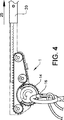
通し装置が係船リングに乗ると、通し装置のハンドル20がユーザ側の方へ引かれる。通し装置は係船リング上にあるので、ハンドル、従って歯付きラックは係船リングから遠ざかり、歯付き弓型要素を回転させる。歯付きベルトのため、歯付き弓型要素は、ハンドルを引くと、反時計方向へ回転する。歯付き弓型要素の回転中、係船リングは、それが滑動する弓型要素の内面上、またはハウジングのリム上のいずれかに存在する。図4で、歯付き弓型要素は通しサイクルのほぼ途中まで転している。綱保持手段は、歯付き弓型要素上を滑動し、綱の重量のため、ここでもなお歯付き弓型要素の下の位置にある。綱保持手段の移動範囲は、弓型要素と本体の肩部15のいずれかにより、または図4に示すように、本体のみのいずれかにより制限される。
When the threading device gets on the mooring ring, the
ハンドルを連続して引くことにより、歯付き弓型要素は回転を続け、図5に示すように、その第2の端部位置へ到達する。この位置で、歯付き弓型要素はその第2の端部位置へ到達し、歯付き弓型要素の開口は、ここでハンドルから離れる方向を向く。綱と共に綱保持手段は、ここで弓型要素の肩部上にある。ピン22は細長い開口21の端部へ到達している。
By continuously pulling the handle, the toothed arch element continues to rotate and reaches its second end position as shown in FIG. In this position, the toothed arch element reaches its second end position, and the opening of the toothed arch element now points away from the handle. The leash holding means together with the leash is now on the shoulder of the bow element. The
ハンドルを連続して引くことにより、弓型要素の開口が、ここで係船リングから離れるので、通し装置全体は係船リングから遠ざかる。同時に、綱は係船リングを通して引かれる。ユーザは綱の端をとり、それをボートへ固定する。通しサイクルはここで終了する。 By pulling the handle continuously, the entire threading device is moved away from the mooring ring, since the opening of the bow element now leaves the mooring ring. At the same time, the leash is pulled through the mooring ring. The user takes the end of the leash and secures it to the boat. The run cycle ends here.
例えばもしユーザがある理由で上陸を中止するならば、通しサイクルも逆にすることもできる。図5の状態に到達し、そしてユーザが通しサイクルを中止したいならば、ユーザは係船リングへ向かってハンドルを押す。ラックが係船リングに向かって押されるので、歯付き弓型要素は、ここで時計回り方向へ回転する。ハンドルを第1停止端へ押すことにより、図1の状態に到達し、綱は係船リングから離れる。上陸はここで中止されるが、または別のより適切な係船リングが代わりに選択される。 For example, if the user stops landing for some reason, the cycle can be reversed. If the state of FIG. 5 is reached and the user wishes to stop the cycle, the user pushes the handle toward the mooring ring. As the rack is pushed towards the mooring ring, the toothed arch element now rotates clockwise. By pushing the handle to the first stop end, the state of FIG. 1 is reached and the leash leaves the mooring ring. Landing is stopped here, or another more suitable mooring ring is selected instead.
係船リングから綱を抜くための逆の可能性を使用することも可能である。例えば嫌な物質やクラゲが水に浮いているならば、ユーザが、綱が水中に落下するのを望まない場合、これは有利である。この場合、通しサイクル全体が逆になる。 It is also possible to use the reverse possibility to remove the leash from the mooring ring. This is advantageous if the user does not want the leash to fall into the water, for example if disgusting substances or jellyfish are floating in the water. In this case, the entire cycle is reversed.
通し装置の一つの改良点で、歯付きベルトの代わりに鎖が使用される。歯付きラックと歯付き弓型要素の歯は、次に鎖と噛み合う。ハンドルを歯付きリングの方へ動かすため、他のタイプのベルトや鎖を使用することも可能である。しかし移動は概ねスリップがないことが重要である。 In one improvement of the threading device, chains are used instead of toothed belts. The teeth of the toothed rack and the toothed arch element then mesh with the chain. Other types of belts or chains can be used to move the handle toward the toothed ring. However, it is important that the movement is almost free of slip.
図7に示す通し装置の別の改良点で、歯付きベルトと車輪8〜10は、歯付き車輪と置換される。この例で、第1の歯付き車輪30と第2の歯付き車輪31が使用される。歯付き車輪は、少なくとも一つの歯付き車輪が歯付き弓型要素と常に接触するように設置される。こうして、歯付き弓型要素は、上記と同様に回転することができる。このように、車輪の位置と、歯付き弓型要素の開口寸法は互いに依存関係にある。
In another refinement of the threading device shown in FIG. 7, the toothed belt and wheels 8-10 are replaced with toothed wheels. In this example, a first
歯付き車輪の寸法は、歯付きラックと歯付き弓形要素の間のギヤー比を設定する。歯付き車輪は、第1の半径を有する第1のセクション32と、第2の半径を有する第2のセクション33の、2つの異なる寸法のセクションからも構成される。表示される例で、第1のセクションの半径32は、第2のセクションの半径33より小さい。半径の選択により、所望のギヤー比が得られる。
The size of the toothed wheel sets the gear ratio between the toothed rack and the toothed arcuate element. The toothed wheel is also composed of two differently sized sections, a
通し装置の別の改良点で、歯付き弓型要素は、ハンドルのグリップ端から回転する。これは別の方法で実施することができる。一例で、歯付きラックはハンドルを通して延び、グリップは延長部端に備えられる。ハンドルを保持し、同時にグリップを操作することにより、歯付きラックを前後に動かすことができ、これにより歯付き弓型要素を回転させる。グリップが回転移動により通し装置を操作するように、変速機を使用することも可能である。ハンドルまたはグリップを回転する弓型要素の方へ押すか、または引くための別の方法も可能である。 In another refinement of the threading device, the toothed arch element rotates from the grip end of the handle. This can be done in other ways. In one example, the toothed rack extends through the handle and a grip is provided at the end of the extension. By holding the handle and simultaneously operating the grip, the toothed rack can be moved back and forth, thereby rotating the toothed arch element. It is also possible to use a transmission so that the grips operate the threading device by rotational movement. Other ways to push or pull the handle or grip towards the rotating arcuate element are possible.
通し装置の別の改良点で、歯付き弓型要素は外側への回転により回転する。歯付きラックを歯付き車輪と置換することにより、歯付きベルトは、代わって歯付き車輪により回転される。歯付き車輪は、例えば電気モータと接続し、こうして弓形要素を回転させる。モータは好ましくは適切なギヤー比を有する変速機を備える。ハンドルは、この例ではハンドルのグリップ端からモータを制御するための電池とスイッチを備える。弓型要素を回転させる別の手段も可能である。モータは、例えばウォーム車輪を駆動する。 In another refinement of the threading device, the toothed arch element is rotated by outward rotation. By replacing the toothed rack with a toothed wheel, the toothed belt is rotated by the toothed wheel instead. The toothed wheel is connected, for example, with an electric motor, thus rotating the arcuate element. The motor preferably comprises a transmission with an appropriate gear ratio. In this example, the handle includes a battery and a switch for controlling the motor from the grip end of the handle. Other means of rotating the arcuate element are possible. The motor drives, for example, a worm wheel.
通し装置の別の改良点で、通し装置はロック作用を備える。ロック作用はハンドル上のノブ等により操作される。ロック作用は、弓型要素が回転できないように、歯付きラックの動きを阻止する。このように、通し装置は通常のボートフックとして使用される。ロック作用は、通し装置を端部位置にロックするか、または弓型要素のロック位置を自由に選択するかのいずれかである。選択可能なロック位置で、通し装置は、あるタイプのグリップ装置として使用される。 In another refinement of the threading device, the threading device has a locking action. The locking action is operated by a knob on the handle. The locking action prevents the toothed rack from moving so that the arcuate element cannot rotate. Thus, the threading device is used as a normal boat hook. The locking action is either to lock the threading device in the end position or to freely select the locking position of the arcuate element. In the selectable locking position, the threading device is used as a type of gripping device.
図8と9に示すような、本発明の第2の実施例で、通し装置101は、取り付け手段でハンドル120へ取り付けるように適合される。ここに示す実施例で、通し装置は2つの四角い開口を通してハンドルへ固定されるが、通し装置をハンドルへ固定するネジやクランプ等のいくつかの異なる方法も可能である。ハンドルへ固定することができる別の通し装置を有する利点は、通し装置がユーザにより既存のハンドル等へ取り付けることができるアクセサリとして供給することができることである。通し装置はハンドルとも一体化され、こうして完全な通し装置ユニットとして供給することもできる。
In a second embodiment of the invention, as shown in FIGS. 8 and 9, the
通し装置101は本体部102を含む。通し装置は、更に第1の側壁104と第2の側壁105を有する中心ビーム103を備える。ビームは、平坦であり、かつ車輪107を移動させるように適合された側壁間に上面106を有する。車輪は、側壁104、105の代わりに車輪を誘導するため、側壁を備える。ビームは、この例では2つの取り付け手段108、109により区切られる。上面の対向する側115は、ビームが弓型要素上をスリップしないまたは滑らないように、高摩擦でビームを弓型要素114の方へ移動させるように適合される。この例で、ビームはスリップを防止するため、ビームに一体化された歯付きラック108に類似する複数の歯を備えるが、スリップを防止するための他の手段も考えられる。
The
ビーム上に上面106上を転がるように適合された車輪107を備える。車輪は、好ましくは低摩擦材料から作られる。車輪を通して、車軸110が備えられる。車輪は、この例では車軸を通して吊り下げられる支持クランプ111を支持する。車軸とアームの端部間で、クランプの各アーム上には、圧縮コイルバネ112が備えられる。クランプの中央部は、摩擦を減らすため、ある種の回転スリーブベアリング113を備える。
A
通し装置は、更に弓型要素114からなる。この例で、弓型要素は外面127上に歯128を備える。歯付き弓型要素は、好ましくは60〜120度の範囲の開口126を備える部分円である。歯付き弓型要素は、好ましくは更に上で述べたように、リングの中心から外へ伸びる歯を備える長方形断面を有する。歯付き弓型要素は、クランプ111によりビームへ保持される。このように、歯付き弓型要素はバネ112によりビームの方向へ引かれる。歯付きラックの歯は、こうして歯付き弓型要素の歯と係合する。歯付き弓型要素は、歯付きラックに対してスリップしないことが重要である。これを保証するため、例えばペグ、リブ、溝またはスプラインなどの歯以外の他の手段も使用される。
The threading device further comprises an
歯付き弓型要素には、内側のライナブッシュの形の綱保持手段116が取り付けられる。綱保持手段は弓型要素に対して回転することができ、綱保持手段が弓型要素と反対方向に回転するので、綱保持手段は、弓型要素内の開口を通過する。従って綱保持手段の開き角度は、弓型要素の開口より大きくなければならず、好ましくは180度より大きい。綱保持手段は、弓型要素内で横方向に綱保持手段を保持するリムを備える。綱保持手段は、弓型要素と同じ半径を有する細長い湾曲した開口119を備える。綱保持手段は、更に弓型要素と同じ、または異なる半径を有する湾曲した内面121を備える。内面121は通しサイクルの少なくとも一部の間に、係船リング上に乗るように適合される。内面寸法は通し装置が適合する係船リング等の寸法に適合する。綱保持手段116は、この例では綱を保持するように適合されたリング117を備える。
Mounted on the toothed arch element is a rope holding means 116 in the form of an inner liner bush. The tow retaining means can rotate relative to the arcuate element and the tow retaining means rotates in the opposite direction to the arcuate element so that the tow retaining means passes through the opening in the arcuate element. The opening angle of the rope holding means must therefore be greater than the opening of the bow element, preferably greater than 180 degrees. The leash holding means comprises a rim that holds the leash holding means laterally within the arcuate element. The leash retaining means comprises an elongated
バネはビームの方向にクランプを引き、これにより歯付きラックに対して歯付き弓型要素を押圧する。力が歯付き弓型要素に加えられると、歯付き弓型要素を歯付きラック上で回転させるバネがクランプに柔軟性を提供する。歯付き弓型要素は、好ましくは頑丈かつ硬い材料から作られる。それは金属の鋳造、または機械加工で作ることができ、又繊維強化ポリアミドなどの強化プラスチックから作ってもよい。弓型要素をステンレスおよび非腐蝕性材料で作ると有利である。 The spring pulls the clamp in the direction of the beam, thereby pressing the toothed arch element against the toothed rack. When force is applied to the toothed arch element, a spring that rotates the toothed arch element on the toothed rack provides flexibility to the clamp. The toothed arch element is preferably made from a sturdy and hard material. It can be made by metal casting or machining, or it can be made from reinforced plastics such as fiber reinforced polyamide. Advantageously, the arcuate element is made of stainless steel and a non-corrosive material.
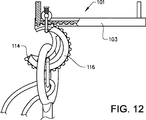
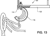
図10〜13は、第2の実施例による本発明の通し装置の通し作用を示す。 10-13 show the threading action of the threading device of the present invention according to the second embodiment.
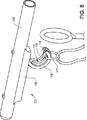
図10で、通し装置が、通しサイクルの開始位置である、第1の端部位置にある状態を示す。係船リング124を通される綱123は、綱保持手段116へ取り付けられる。綱保持手段は、通しサイクル中に綱を保持することができる、例えば、クランプ、クリップ、シャックル、リング等の適切な手段である。表示例で、綱保持手段116は綱が通されるリング117を備える。綱123は、それが通し作用中に落下しないように、リング117を通して供給される。もし綱がループ等を備えておれば、それはある種のクランプでリング117へ取り付けることもできる。リング117は、綱を固定する柔軟な舌部など、ある種の保持手段を備える。綱の開口が細長い開口を置換し、綱保持手段の開口に綱を通すことも可能である。この場合、開口は、好ましくは綱保持手段に対称に設置される。弓型要素の自由端が綱を保持する綱保持手段の一部と共に係船リングを通して伸びるように、綱が綱保持手段に取り付けられ、通し装置の弓形要素114は綱保持手段と共に係船リングへ設置される。ボートが通しサイクル中、所定位置に保持できるように、通し装置は、同時にボートフックとして機能する。
FIG. 10 shows the threading device in the first end position, which is the starting position of the threading cycle. The
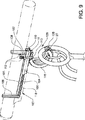
綱保持手段の内面が係船リング上にある場合、ハンドル、従って通し装置は、矢印122で表示される方向に、ユーザの方へ引かれる。綱保持手段が係船リング上にあるので、ハンドルの引きにより、係船リングから綱保持手段へ力が作用する。綱保持手段の力は、歯付き弓型要素へ作用し、これが次にクランプをやや下向きに引き、矢印122とやや反対の方向へクランプも傾斜させる。バネ112はクランプのこの屈曲を許容し、次にこれが歯付き弓型要素の歯付きラックに対する回転を許容する。歯付き弓型要素は時計方向へ回転する。同時に、綱保持要素は反時計方向へ回転する。綱保持手段の角度位置は、サイクル中に、例えば綱の重さにより、および係船リングが歯付き弓型要素上にある位置により変化する。
When the inner surface of the leash holding means is on the mooring ring, the handle, and hence the threading device, is pulled towards the user in the direction indicated by
歯付き弓型要素の回転中、綱保持手段は歯付き弓型要素の中を滑り、綱の重さとバランスする。綱保持手段の位置に依存して、綱を保持するリングの位置は、細長い開口内で変動する。図11で、歯付き弓型要素は通しサイクルの途中まで回転している。 During rotation of the toothed arch element, the leash holding means slides in the toothed arch element and balances the weight of the leash. Depending on the position of the leash holding means, the position of the ring holding the leash varies within the elongated opening. In FIG. 11, the toothed arch element has been rotated halfway through.
ハンドルを連続して引くことにより、歯付き弓型要素は回転を続け、図12に示すように、その第2の端部位置へ到達する。この位置で、歯付き弓型要素はその第2の端部位置へ到達し、開口はここでハンドルから遠ざかる方向を向く。綱保持手段は綱と共に回転し、ここで他の側から回転スリーブベアリング113上に乗る。 By continuously pulling the handle, the toothed arch element continues to rotate and reaches its second end position, as shown in FIG. In this position, the toothed arch element reaches its second end position, with the opening now pointing away from the handle. The leash holding means rotates with the leash, where it rides on the rotating sleeve bearing 113 from the other side.
ハンドルを連続して引くことにより、歯付き弓型要素の開口がここで係船リングから離れるので、通し装置全体は係船リングから遠ざかる。仮に綱保持手段がより水平な位置にあれば、それは係船リングと接触することか、または綱の重さか、またはこの二つの組み合わせのいずれかにより、この引き中に、図12に示すような位置へ動く。同時に、綱は係船リングを通して引かれる。ユーザはここで綱の端を取り、それをボートへ固定する。通しサイクルはこれで終了する。 By pulling the handle continuously, the entire threading device moves away from the mooring ring, since the opening of the toothed arch element now leaves the mooring ring. If the leash holding means is in a more horizontal position, it will contact the mooring ring, or the weight of the leash, or a combination of the two, during this pull, as shown in FIG. Move to. At the same time, the leash is pulled through the mooring ring. The user now takes the end of the leash and secures it to the boat. This completes the cycle.
例えばもしユーザがある理由で上陸を中止することを決定すれば、通しサイクルは逆にすることもできる。もし図12の状態に到達し、ユーザが通しサイクルを中止したいならば、ユーザは係船リングの方へハンドルを押す。弓型要素はここで反時計回方向へ回転し、ハンドル、従ってラックが係船リングの方へ押されるので、綱保持手段は時計方向に回転する。クランプは、この場合、弓型要素の回転を可能にするため、反対方向へ屈曲する。ハンドルを第1の停止端へ押すことにより、図10の状態に到達し、綱は係船リングから離れる。上陸はここで中止されるか、または別のより適切な係船リングが代わりに選択される。 For example, if the user decides to stop landing for some reason, the through cycle can be reversed. If the state of FIG. 12 is reached and the user wishes to stop the cycle, the user pushes the handle toward the mooring ring. The bow element now rotates counterclockwise and the leash retaining means rotates clockwise as the handle, and hence the rack, is pushed towards the mooring ring. The clamp in this case bends in the opposite direction to allow rotation of the arcuate element. By pushing the handle to the first stop end, the state of FIG. 10 is reached and the leash leaves the mooring ring. Landing is stopped here or another more appropriate mooring ring is selected instead.
綱を係船リングから抜くための逆の可能性を利用することも可能である。例えばもし嫌な物質またはクラゲが水に浮遊していれば、ユーザが綱の水中への落下を望まない場合、これは有利である。この場合、通しサイクル全体が逆転する。 It is also possible to take advantage of the reverse possibility to pull the leash from the mooring ring. This is advantageous if the user does not want the rope to fall into the water, for example if disgusting substances or jellyfish are floating in the water. In this case, the entire cycle is reversed.
通し装置の改良点で、歯付き弓型要素はハンドルのグリップ端から回転する。これは、異なる方法でも行うことができる。一例で、歯付きビームが本体内で滑るように吊り下げられる。ビームはハンドルを通して伸ばされ、グリップは延長部端部に備えられる。ハンドルを保持することにより、同時にグリップを操作することにより、歯付きビームを前後に動かすことができ、これにより歯付き弓型要素を回転させる。車輪を押し、および引くため、力伝達手段を使用してハンドルのグリップからクランプと共に車輪を駆動することも可能である。ハンドルまたはグリップの回転する弓型要素への押し、または引きの伝達の別の方法も可能である。変速機を備えた電気モータで、弓型要素を回転させることも可能である。モータは直接、弓型要素を駆動するか、または歯付きラックを駆動する。 With the threading device improvement, the toothed arch element rotates from the grip end of the handle. This can be done in different ways. In one example, the toothed beam is suspended to slide within the body. The beam is extended through the handle and a grip is provided at the end of the extension. By holding the handle, the toothed beam can be moved back and forth by simultaneously manipulating the grip, thereby rotating the toothed arch element. It is also possible to drive the wheel together with the clamp from the handle grip using force transmission means to push and pull the wheel. Other methods of pushing or pulling the handle or grip to the rotating arcuate element are possible. It is also possible to rotate the bow element with an electric motor equipped with a transmission. The motor directly drives the arcuate element or drives the toothed rack.
本発明は上記実施例に限定されると見なすべきでなく、多くの追加的変形や修正が続く特許請求項の範囲内で可能である。例えば、通し装置を異なるタイプのハンドルに一体化することが可能であり、回転可能な弓型要素を請求項で包含される多くの方法で、通し装置本体内に吊り下げることができる。 The present invention should not be regarded as limited to the above embodiments, but many additional variations and modifications are possible within the scope of the following claims. For example, the threading device can be integrated into different types of handles, and the rotatable arcuate element can be suspended within the threading device body in many ways encompassed by the claims.
1、101:通し装置
2、102:本体
3、104:第1の側壁
4、105:第2の側壁
5:第1のボルト
6:第2のボルト
7:第3のボルト
8:第1の車輪
9:第2の車輪
10:第3の車輪
11:歯付きベルト
12:凹部
13:リム
14、114:弓形要素
15:肩部
16、116:綱保持手段
17、117:リング
18、118:歯付きラック
19:管状延長部
20、120:ハンドル
21、119:細長い開口
22:ピン
23、123:綱
24、124:係船リング
25、122:引き方向
26、126:開口
27、127:外面
28、128:歯
31:第1の歯付き車輪
32:第2の歯付き車輪
33:第1のセクション
34:第2のセクション
103:ビーム
106:上面
107:車輪
108、109:取付け手段
110:車軸
111:クランプ
112:バネ
113:スリーブベアリング
115:下面
121:内面
DESCRIPTION OF SYMBOLS 1,101: Passing
Claims (9)
Applications Claiming Priority (1)
| Application Number | Priority Date | Filing Date | Title |
|---|---|---|---|
| PCT/SE2008/050418 WO2009126082A1 (en) | 2008-04-11 | 2008-04-11 | Threading device |
Publications (2)
| Publication Number | Publication Date |
|---|---|
| JP2011516340A JP2011516340A (en) | 2011-05-26 |
| JP5115895B2 true JP5115895B2 (en) | 2013-01-09 |
Family
ID=41050758
Family Applications (1)
| Application Number | Title | Priority Date | Filing Date |
|---|---|---|---|
| JP2011503935A Active JP5115895B2 (en) | 2008-04-11 | 2008-04-11 | Threading device |
Country Status (13)
| Country | Link |
|---|---|
| US (1) | US8312830B2 (en) |
| EP (1) | EP2271545B1 (en) |
| JP (1) | JP5115895B2 (en) |
| CN (1) | CN102317148B (en) |
| AU (1) | AU2008354412B2 (en) |
| CA (1) | CA2719649C (en) |
| CY (1) | CY1114344T1 (en) |
| DK (1) | DK2271545T3 (en) |
| ES (1) | ES2415204T3 (en) |
| HR (1) | HRP20130555T1 (en) |
| PL (1) | PL2271545T3 (en) |
| PT (1) | PT2271545E (en) |
| WO (2) | WO2009126082A1 (en) |
Families Citing this family (14)
| Publication number | Priority date | Publication date | Assignee | Title |
|---|---|---|---|---|
| ITMI20090156U1 (en) * | 2009-05-13 | 2010-11-14 | Teruzzi Enrico | DEVICE FOR SHUTTLE BOATS |
| WO2011109298A2 (en) | 2010-03-02 | 2011-09-09 | Abbott Laboratories | Therapeutic dll4 binding proteins |
| DE202011051145U1 (en) * | 2011-08-29 | 2012-01-02 | Horst Herold | boathook |
| CN106081015A (en) * | 2016-06-28 | 2016-11-09 | 河北工业大学 | A kind of submarine navigation device bridle catcher |
| GB2568535B (en) | 2017-11-20 | 2020-12-02 | Svitzer As | Line handling system for coupling together lines on a tugboat |
| GB2568534B (en) | 2017-11-20 | 2020-12-02 | Svitzer As | Tugboat with a moveable line guide mechanism |
| GB2568533B (en) | 2017-11-20 | 2020-12-02 | Svitzer As | Tugboat having a line handling system |
| CN109330651A (en) * | 2018-11-09 | 2019-02-15 | 大竹县人民医院 | Multi-functional braiding machine |
| CN111120578B (en) * | 2019-12-27 | 2021-06-01 | 中国航空工业集团公司西安飞机设计研究所 | Emergency separation device |
| CN111288281A (en) * | 2020-02-14 | 2020-06-16 | 魏长同 | Flagpole hanging rope device |
| CN111348147A (en) * | 2020-02-21 | 2020-06-30 | 魏磊 | Cable penetrating device |
| CN115151480A (en) * | 2020-03-06 | 2022-10-04 | 斯维特泽尔公司 | Cable handling device and vessel comprising a cable handling device |
| PE20230098A1 (en) * | 2020-03-06 | 2023-01-19 | Svitzer As | MOORING DEVICE, MOORING SYSTEM AND VESSEL |
| CN114336434B (en) | 2021-12-24 | 2022-10-11 | 泰州市达维电器有限公司 | Threading apparatus suitable for building electric pipeline |
Family Cites Families (14)
| Publication number | Priority date | Publication date | Assignee | Title |
|---|---|---|---|---|
| GB287407A (en) | 1927-09-24 | 1928-03-22 | Clifford Hugh Douglas | Improvements in ship-mooring devices |
| GB442857A (en) * | 1934-06-14 | 1936-02-14 | Richardson Peter Moffat | Improvements in mooring devices |
| GB723835A (en) * | 1952-09-30 | 1955-02-09 | John Leslie Wingate | Implement for engaging a line with a remote object |
| GB2130157B (en) * | 1982-11-09 | 1986-02-19 | Latchways Ltd | Threading device |
| JPS59100081A (en) * | 1982-11-09 | 1984-06-09 | ラツチウエイズ・リミテツド | Device for passing wire |
| JPH035517Y2 (en) * | 1985-04-16 | 1991-02-13 | ||
| SE453176B (en) * | 1985-04-23 | 1988-01-18 | Torsthen Martinsson | Tool for drawing line through loop |
| GB8715340D0 (en) * | 1987-06-30 | 1987-08-05 | Tupper A W | Threading & hoisting devices & systems |
| JPH0191608A (en) * | 1987-06-30 | 1989-04-11 | Alan W Tupper | Apparatus for casting and winding-up net |
| FI85000C (en) * | 1989-08-24 | 1992-02-25 | Heikki Matti Akseli Heimala | Self-supporting buoyancy hook |
| WO1996011836A1 (en) * | 1994-10-12 | 1996-04-25 | Hugues Gabriel Benois | Mooring boat hook with a rope-through device |
| CA2151653A1 (en) * | 1995-06-13 | 1996-12-14 | H. James Peever | Mooring line hook |
| JP2003160094A (en) * | 2001-11-26 | 2003-06-03 | Shoji Miyoshi | Steering device |
| DE102006029810B4 (en) * | 2006-06-28 | 2009-12-24 | Dietmar Simsheuser | Device for guiding a leash around a ring |
-
2008
- 2008-04-11 CA CA2719649A patent/CA2719649C/en active Active
- 2008-04-11 WO PCT/SE2008/050418 patent/WO2009126082A1/en active Application Filing
- 2008-04-11 AU AU2008354412A patent/AU2008354412B2/en active Active
- 2008-04-11 CN CN200880129282.8A patent/CN102317148B/en active Active
- 2008-04-11 JP JP2011503935A patent/JP5115895B2/en active Active
-
2009
- 2009-04-07 PT PT97311005T patent/PT2271545E/en unknown
- 2009-04-07 WO PCT/EP2009/054145 patent/WO2009124934A1/en active Application Filing
- 2009-04-07 DK DK09731100.5T patent/DK2271545T3/en active
- 2009-04-07 US US12/937,267 patent/US8312830B2/en active Active
- 2009-04-07 ES ES09731100T patent/ES2415204T3/en active Active
- 2009-04-07 EP EP09731100A patent/EP2271545B1/en active Active
- 2009-04-07 PL PL09731100T patent/PL2271545T3/en unknown
-
2013
- 2013-06-18 HR HRP20130555AT patent/HRP20130555T1/en unknown
- 2013-06-19 CY CY20131100496T patent/CY1114344T1/en unknown
Also Published As
| Publication number | Publication date |
|---|---|
| AU2008354412B2 (en) | 2013-06-27 |
| DK2271545T3 (en) | 2013-06-24 |
| AU2008354412A1 (en) | 2009-10-15 |
| WO2009124934A1 (en) | 2009-10-15 |
| CA2719649A1 (en) | 2009-10-15 |
| WO2009126082A1 (en) | 2009-10-15 |
| US8312830B2 (en) | 2012-11-20 |
| JP2011516340A (en) | 2011-05-26 |
| ES2415204T3 (en) | 2013-07-24 |
| PL2271545T3 (en) | 2013-09-30 |
| US20110030605A1 (en) | 2011-02-10 |
| CN102317148B (en) | 2014-08-13 |
| PT2271545E (en) | 2013-06-25 |
| EP2271545A1 (en) | 2011-01-12 |
| CN102317148A (en) | 2012-01-11 |
| CY1114344T1 (en) | 2016-08-31 |
| CA2719649C (en) | 2015-04-07 |
| HRP20130555T1 (en) | 2013-08-31 |
| EP2271545B1 (en) | 2013-03-20 |
Similar Documents
| Publication | Publication Date | Title |
|---|---|---|
| JP5115895B2 (en) | Threading device | |
| US8327788B1 (en) | Mooring pendant apparatus | |
| MXPA06009071A (en) | Boat docking rope cuffs. | |
| US4213413A (en) | Water ski tow assembly | |
| AU2012262677B2 (en) | A hook | |
| US6769377B2 (en) | Gear driven outrigger positioner | |
| US8443747B1 (en) | Mooring pendant apparatus | |
| US7198219B1 (en) | Fishing reel transmission | |
| US6295936B1 (en) | Portable rope tow device | |
| US2983243A (en) | Boat anchor | |
| US20140000503A1 (en) | Anchor for Boats | |
| US3281120A (en) | Winch assembly | |
| SE533037C2 (en) | Threading Device | |
| US616176A (en) | Wire-stretcher | |
| GB2448696A (en) | Retractable boat mooring tether | |
| US3599592A (en) | Releasable mooring rope | |
| US345268A (en) | William l | |
| US5421280A (en) | Anchor chain orientation link | |
| JP3155653U (en) | Squid fishing equipment | |
| US8764343B1 (en) | Boat-launching device, system, and method | |
| EP2955097A1 (en) | A weight device for an anchor line | |
| US1254570A (en) | Rope-grip. | |
| JP2023121095A (en) | Mooring device, cooking tool | |
| US556917A (en) | Harold w | |
| GB2272875A (en) | A mooring implement |
Legal Events
| Date | Code | Title | Description |
|---|---|---|---|
| A621 | Written request for application examination |
Free format text: JAPANESE INTERMEDIATE CODE: A621 Effective date: 20110314 |
|
| A521 | Request for written amendment filed |
Free format text: JAPANESE INTERMEDIATE CODE: A523 Effective date: 20120314 |
|
| A977 | Report on retrieval |
Free format text: JAPANESE INTERMEDIATE CODE: A971007 Effective date: 20120925 |
|
| TRDD | Decision of grant or rejection written | ||
| A01 | Written decision to grant a patent or to grant a registration (utility model) |
Free format text: JAPANESE INTERMEDIATE CODE: A01 Effective date: 20121002 |
|
| A01 | Written decision to grant a patent or to grant a registration (utility model) |
Free format text: JAPANESE INTERMEDIATE CODE: A01 |
|
| A61 | First payment of annual fees (during grant procedure) |
Free format text: JAPANESE INTERMEDIATE CODE: A61 Effective date: 20121005 |
|
| R150 | Certificate of patent or registration of utility model |
Free format text: JAPANESE INTERMEDIATE CODE: R150 Ref document number: 5115895 Country of ref document: JP Free format text: JAPANESE INTERMEDIATE CODE: R150 |
|
| FPAY | Renewal fee payment (event date is renewal date of database) |
Free format text: PAYMENT UNTIL: 20151026 Year of fee payment: 3 |
|
| R250 | Receipt of annual fees |
Free format text: JAPANESE INTERMEDIATE CODE: R250 |
|
| R250 | Receipt of annual fees |
Free format text: JAPANESE INTERMEDIATE CODE: R250 |
|
| R250 | Receipt of annual fees |
Free format text: JAPANESE INTERMEDIATE CODE: R250 |
|
| R250 | Receipt of annual fees |
Free format text: JAPANESE INTERMEDIATE CODE: R250 |
|
| R250 | Receipt of annual fees |
Free format text: JAPANESE INTERMEDIATE CODE: R250 |
|
| R250 | Receipt of annual fees |
Free format text: JAPANESE INTERMEDIATE CODE: R250 |
|
| R250 | Receipt of annual fees |
Free format text: JAPANESE INTERMEDIATE CODE: R250 |
|
| R250 | Receipt of annual fees |
Free format text: JAPANESE INTERMEDIATE CODE: R250 |
|
| R250 | Receipt of annual fees |
Free format text: JAPANESE INTERMEDIATE CODE: R250 |