JP5114995B2 - Heat-resistant light-shielding film, method for producing the same, and diaphragm or light amount adjusting device using the same - Google Patents
Heat-resistant light-shielding film, method for producing the same, and diaphragm or light amount adjusting device using the same Download PDFInfo
- Publication number
- JP5114995B2 JP5114995B2 JP2007084119A JP2007084119A JP5114995B2 JP 5114995 B2 JP5114995 B2 JP 5114995B2 JP 2007084119 A JP2007084119 A JP 2007084119A JP 2007084119 A JP2007084119 A JP 2007084119A JP 5114995 B2 JP5114995 B2 JP 5114995B2
- Authority
- JP
- Japan
- Prior art keywords
- film
- heat
- shielding
- resistant light
- light
- Prior art date
- Legal status (The legal status is an assumption and is not a legal conclusion. Google has not performed a legal analysis and makes no representation as to the accuracy of the status listed.)
- Expired - Fee Related
Links
Images


Classifications
-
- B—PERFORMING OPERATIONS; TRANSPORTING
- B32—LAYERED PRODUCTS
- B32B—LAYERED PRODUCTS, i.e. PRODUCTS BUILT-UP OF STRATA OF FLAT OR NON-FLAT, e.g. CELLULAR OR HONEYCOMB, FORM
- B32B27/00—Layered products comprising a layer of synthetic resin
- B32B27/28—Layered products comprising a layer of synthetic resin comprising synthetic resins not wholly covered by any one of the sub-groups B32B27/30 - B32B27/42
-
- C—CHEMISTRY; METALLURGY
- C23—COATING METALLIC MATERIAL; COATING MATERIAL WITH METALLIC MATERIAL; CHEMICAL SURFACE TREATMENT; DIFFUSION TREATMENT OF METALLIC MATERIAL; COATING BY VACUUM EVAPORATION, BY SPUTTERING, BY ION IMPLANTATION OR BY CHEMICAL VAPOUR DEPOSITION, IN GENERAL; INHIBITING CORROSION OF METALLIC MATERIAL OR INCRUSTATION IN GENERAL
- C23C—COATING METALLIC MATERIAL; COATING MATERIAL WITH METALLIC MATERIAL; SURFACE TREATMENT OF METALLIC MATERIAL BY DIFFUSION INTO THE SURFACE, BY CHEMICAL CONVERSION OR SUBSTITUTION; COATING BY VACUUM EVAPORATION, BY SPUTTERING, BY ION IMPLANTATION OR BY CHEMICAL VAPOUR DEPOSITION, IN GENERAL
- C23C14/00—Coating by vacuum evaporation, by sputtering or by ion implantation of the coating forming material
- C23C14/06—Coating by vacuum evaporation, by sputtering or by ion implantation of the coating forming material characterised by the coating material
- C23C14/14—Metallic material, boron or silicon
- C23C14/20—Metallic material, boron or silicon on organic substrates
- C23C14/205—Metallic material, boron or silicon on organic substrates by cathodic sputtering
-
- C—CHEMISTRY; METALLURGY
- C23—COATING METALLIC MATERIAL; COATING MATERIAL WITH METALLIC MATERIAL; CHEMICAL SURFACE TREATMENT; DIFFUSION TREATMENT OF METALLIC MATERIAL; COATING BY VACUUM EVAPORATION, BY SPUTTERING, BY ION IMPLANTATION OR BY CHEMICAL VAPOUR DEPOSITION, IN GENERAL; INHIBITING CORROSION OF METALLIC MATERIAL OR INCRUSTATION IN GENERAL
- C23C—COATING METALLIC MATERIAL; COATING MATERIAL WITH METALLIC MATERIAL; SURFACE TREATMENT OF METALLIC MATERIAL BY DIFFUSION INTO THE SURFACE, BY CHEMICAL CONVERSION OR SUBSTITUTION; COATING BY VACUUM EVAPORATION, BY SPUTTERING, BY ION IMPLANTATION OR BY CHEMICAL VAPOUR DEPOSITION, IN GENERAL
- C23C14/00—Coating by vacuum evaporation, by sputtering or by ion implantation of the coating forming material
- C23C14/0021—Reactive sputtering or evaporation
- C23C14/0036—Reactive sputtering
-
- C—CHEMISTRY; METALLURGY
- C23—COATING METALLIC MATERIAL; COATING MATERIAL WITH METALLIC MATERIAL; CHEMICAL SURFACE TREATMENT; DIFFUSION TREATMENT OF METALLIC MATERIAL; COATING BY VACUUM EVAPORATION, BY SPUTTERING, BY ION IMPLANTATION OR BY CHEMICAL VAPOUR DEPOSITION, IN GENERAL; INHIBITING CORROSION OF METALLIC MATERIAL OR INCRUSTATION IN GENERAL
- C23C—COATING METALLIC MATERIAL; COATING MATERIAL WITH METALLIC MATERIAL; SURFACE TREATMENT OF METALLIC MATERIAL BY DIFFUSION INTO THE SURFACE, BY CHEMICAL CONVERSION OR SUBSTITUTION; COATING BY VACUUM EVAPORATION, BY SPUTTERING, BY ION IMPLANTATION OR BY CHEMICAL VAPOUR DEPOSITION, IN GENERAL
- C23C14/00—Coating by vacuum evaporation, by sputtering or by ion implantation of the coating forming material
- C23C14/06—Coating by vacuum evaporation, by sputtering or by ion implantation of the coating forming material characterised by the coating material
- C23C14/08—Oxides
- C23C14/085—Oxides of iron group metals
-
- C—CHEMISTRY; METALLURGY
- C23—COATING METALLIC MATERIAL; COATING MATERIAL WITH METALLIC MATERIAL; CHEMICAL SURFACE TREATMENT; DIFFUSION TREATMENT OF METALLIC MATERIAL; COATING BY VACUUM EVAPORATION, BY SPUTTERING, BY ION IMPLANTATION OR BY CHEMICAL VAPOUR DEPOSITION, IN GENERAL; INHIBITING CORROSION OF METALLIC MATERIAL OR INCRUSTATION IN GENERAL
- C23C—COATING METALLIC MATERIAL; COATING MATERIAL WITH METALLIC MATERIAL; SURFACE TREATMENT OF METALLIC MATERIAL BY DIFFUSION INTO THE SURFACE, BY CHEMICAL CONVERSION OR SUBSTITUTION; COATING BY VACUUM EVAPORATION, BY SPUTTERING, BY ION IMPLANTATION OR BY CHEMICAL VAPOUR DEPOSITION, IN GENERAL
- C23C14/00—Coating by vacuum evaporation, by sputtering or by ion implantation of the coating forming material
- C23C14/22—Coating by vacuum evaporation, by sputtering or by ion implantation of the coating forming material characterised by the process of coating
- C23C14/56—Apparatus specially adapted for continuous coating; Arrangements for maintaining the vacuum, e.g. vacuum locks
- C23C14/562—Apparatus specially adapted for continuous coating; Arrangements for maintaining the vacuum, e.g. vacuum locks for coating elongated substrates
-
- Y—GENERAL TAGGING OF NEW TECHNOLOGICAL DEVELOPMENTS; GENERAL TAGGING OF CROSS-SECTIONAL TECHNOLOGIES SPANNING OVER SEVERAL SECTIONS OF THE IPC; TECHNICAL SUBJECTS COVERED BY FORMER USPC CROSS-REFERENCE ART COLLECTIONS [XRACs] AND DIGESTS
- Y10—TECHNICAL SUBJECTS COVERED BY FORMER USPC
- Y10T—TECHNICAL SUBJECTS COVERED BY FORMER US CLASSIFICATION
- Y10T428/00—Stock material or miscellaneous articles
- Y10T428/12—All metal or with adjacent metals
- Y10T428/12493—Composite; i.e., plural, adjacent, spatially distinct metal components [e.g., layers, joint, etc.]
- Y10T428/12771—Transition metal-base component
- Y10T428/12806—Refractory [Group IVB, VB, or VIB] metal-base component
- Y10T428/12826—Group VIB metal-base component
-
- Y—GENERAL TAGGING OF NEW TECHNOLOGICAL DEVELOPMENTS; GENERAL TAGGING OF CROSS-SECTIONAL TECHNOLOGIES SPANNING OVER SEVERAL SECTIONS OF THE IPC; TECHNICAL SUBJECTS COVERED BY FORMER USPC CROSS-REFERENCE ART COLLECTIONS [XRACs] AND DIGESTS
- Y10—TECHNICAL SUBJECTS COVERED BY FORMER USPC
- Y10T—TECHNICAL SUBJECTS COVERED BY FORMER US CLASSIFICATION
- Y10T428/00—Stock material or miscellaneous articles
- Y10T428/12—All metal or with adjacent metals
- Y10T428/12493—Composite; i.e., plural, adjacent, spatially distinct metal components [e.g., layers, joint, etc.]
- Y10T428/12771—Transition metal-base component
- Y10T428/12861—Group VIII or IB metal-base component
- Y10T428/12944—Ni-base component
-
- Y—GENERAL TAGGING OF NEW TECHNOLOGICAL DEVELOPMENTS; GENERAL TAGGING OF CROSS-SECTIONAL TECHNOLOGIES SPANNING OVER SEVERAL SECTIONS OF THE IPC; TECHNICAL SUBJECTS COVERED BY FORMER USPC CROSS-REFERENCE ART COLLECTIONS [XRACs] AND DIGESTS
- Y10—TECHNICAL SUBJECTS COVERED BY FORMER USPC
- Y10T—TECHNICAL SUBJECTS COVERED BY FORMER US CLASSIFICATION
- Y10T428/00—Stock material or miscellaneous articles
- Y10T428/24—Structurally defined web or sheet [e.g., overall dimension, etc.]
- Y10T428/24942—Structurally defined web or sheet [e.g., overall dimension, etc.] including components having same physical characteristic in differing degree
- Y10T428/2495—Thickness [relative or absolute]
- Y10T428/24967—Absolute thicknesses specified
-
- Y—GENERAL TAGGING OF NEW TECHNOLOGICAL DEVELOPMENTS; GENERAL TAGGING OF CROSS-SECTIONAL TECHNOLOGIES SPANNING OVER SEVERAL SECTIONS OF THE IPC; TECHNICAL SUBJECTS COVERED BY FORMER USPC CROSS-REFERENCE ART COLLECTIONS [XRACs] AND DIGESTS
- Y10—TECHNICAL SUBJECTS COVERED BY FORMER USPC
- Y10T—TECHNICAL SUBJECTS COVERED BY FORMER US CLASSIFICATION
- Y10T428/00—Stock material or miscellaneous articles
- Y10T428/26—Web or sheet containing structurally defined element or component, the element or component having a specified physical dimension
Description
本発明は、耐熱遮光フィルムとその製造方法、及びそれを用いた絞り又は光量調整装置に関し、より詳しくは、デジタルカメラ、デジタルビデオカメラの絞りやレンズシャッターなどのシャッター羽根または絞り羽根、プロジェクターの光量調整用絞り装置の絞り羽根などの光学機器部品として用いられ、遮光性、耐熱性、摺動性、低光沢性、導電性に優れた耐熱遮光フィルムとその製造方法、及びそれを用いた絞り又は光量調整装置に関する。 The present invention relates to a heat-resistant light-shielding film, a manufacturing method thereof, and an aperture or light amount adjusting device using the same, and more specifically, shutter blades or aperture blades of a digital camera, a digital video camera, a lens shutter, and the like, a light amount of a projector A heat-resistant light-shielding film excellent in light-shielding property, heat resistance, slidability, low glossiness, and conductivity, and a method for producing the same, and a diaphragm or the like used as an optical device part such as a diaphragm blade of an adjusting diaphragm device The present invention relates to a light amount adjusting device.
現在、カメラ用のシャッター羽根や絞り羽根は、シャッタースピードが高速化し、極めて短時間に動作と停止を行うので、軽量化かつ高摺動性である必要がある。また、フィルムなどの感光材、CCDなどの撮像素子の前面を覆って光を遮るものなので、基本的に遮光性を必要とする。更に、光学機器用の羽根は、複数枚が互いに重なり合って動作するので滑らかな動作のために潤滑性が必要となる。また、各羽根間の漏れ光を防ぐために表面の反射率は低いことが望まれる。使用環境によっては、カメラ内部が高温となる場合があり、耐熱性が求められている。
一方、プレゼンテーション、ホームシアターなどの映像観賞用の投影装置である液晶プロジェクターの光量調整用絞り羽根として使用される遮光フィルムにおいても、デジタルカメラ、デジタルビデオカメラと同様な特性が求められ、特に耐熱性に関しては、カメラ以上の特性が求められている。
At present, shutter blades and diaphragm blades for cameras have a high shutter speed and operate and stop in a very short time. In addition, since light is blocked by covering the front surface of a photosensitive material such as a film and an image pickup device such as a CCD, basically, light shielding is required. Furthermore, since a plurality of blades for an optical device operate while overlapping each other, lubricity is required for smooth operation. Moreover, in order to prevent the leak light between each blade | wing, it is desired that the surface reflectance is low. Depending on the usage environment, the inside of the camera may become hot, and heat resistance is required.
On the other hand, the same characteristics as digital cameras and digital video cameras are also required for light-shielding films used as light quantity adjustment diaphragm blades for liquid crystal projectors, which are projection devices for viewing images such as presentations and home theaters. Therefore, characteristics superior to those of cameras are required.
一般的に、上記遮光フィルムは、ポリエチレンテレフタレート(PET)などのプラスチックフィルムやSUS、SK材、Al等の金属薄板を基材としたものが実用化されている。カメラでは、基材が金属性の遮光フィルムをシャッター羽根、絞り羽根として用いる場合、羽根材を開閉する際に、金属板同士が擦れあって大きな騒音が発生する。また、液晶プロジェクターでは、映像が変化するときに各画像の輝度変化を和らげるために羽根を高速で移動する必要があり、羽根同士が擦れの騒音を繰り返すことになる。また、この騒音を低減するためには羽根を低速で動作することになり、この場合、画像の変化に光量調整が追いつかず、画像が不安定となるという問題があった。
前記問題や軽量化の観点から、近年の遮光フィルムの構成は、プラスチックフィルムを基材に用いることが主流となってきている。更に、発塵性の点から導電性も求められている。上記から、遮光フィルムの必要特性は、高遮光性、耐熱性、低光沢性、摺動性、導電性、低発塵性であるとされている。このような遮光フィルムの特性を満足するために、従来からさまざまな材料、フィルム構造を用いたものが提案されている。
In general, the light-shielding film has been put to practical use with a plastic film such as polyethylene terephthalate (PET) or a metal thin plate such as SUS, SK material, or Al as a base material. In a camera, when a light shielding film having a metallic base material is used as a shutter blade or a diaphragm blade, when the blade material is opened and closed, the metal plates rub against each other and generate a large noise. Further, in the liquid crystal projector, it is necessary to move the blades at a high speed in order to relieve the luminance change of each image when the image changes, and the blades repeatedly rub each other. In order to reduce the noise, the blades are operated at a low speed. In this case, there is a problem that the light amount adjustment cannot catch up with the change in the image and the image becomes unstable.
From the viewpoint of the above-mentioned problems and weight reduction, it has become the mainstream in recent years to use a plastic film as a base material for a light shielding film. Furthermore, conductivity is also required from the viewpoint of dust generation. From the above, it is said that the necessary characteristics of the light shielding film are high light shielding properties, heat resistance, low glossiness, slidability, conductivity, and low dust generation. In order to satisfy such properties of the light shielding film, various materials and film structures have been proposed.
例えば、特許文献1には、遮光性、低光沢性、導電性の点からランプ光源等から発せられる光を吸収させるためにカーボンブラック、チタンブラック等の導電性黒色微粒子をポリエチレンテレフタレート(PET)フィルムなどの樹脂フィルムに含浸させ遮光性及び導電性を持たせ、更に遮光フィルムの片面または両面をマット処理し、低光沢性とした遮光フィルムが開示されている。
特許文献2では、樹脂フィルム上に、遮光性と導電性を有するカーボンブラックなどの黒色顔料や潤滑剤、艶消し剤を含有した熱硬化性樹脂層を塗布し、遮光性、導電性、潤滑性、低光沢性を付与した遮光フィルムが開示されている。
特許文献3では、アルミニウム合金などの金属製羽根材料の表面に硬質炭素膜を形成した遮光材が開示されている。
特許文献4では、遮光羽根の剛性を高めるためプラスチック基材の両面に炭素繊維を含有する熱硬化性樹脂のプリプレグシートで強化した遮光羽根の構造が開示されている。
For example,
In Patent Document 2, a thermosetting resin layer containing a black pigment such as carbon black having a light-shielding property and conductivity, a lubricant, and a matting agent is applied on a resin film to provide light-shielding property, conductivity, and lubricity. A light-shielding film imparted with low gloss is disclosed.
遮光フィルムは、デジタルカメラ、デジタルビデオカメラ、液晶プロジェクター等の光学機器用遮光羽材として広く使用されている。近年、液晶プロジェクターではリビングルームといった明るい環境下でも鮮やかなハイコントラストな映像が楽しめるように高画質化の要求が高まっている。したがって、画質の高輝度化によりランプ光源が高出力となるため、光量調整用の絞り装置内の温度が高くなる傾向にある。光量を調整する遮光フィルムへ高出力な光が照射されるため、遮光フィルムが熱変形しやすい環境となっている。 The light shielding film is widely used as a light shielding material for optical devices such as digital cameras, digital video cameras, and liquid crystal projectors. In recent years, there has been an increasing demand for liquid crystal projectors with high image quality so that vivid high-contrast images can be enjoyed even in a bright environment such as a living room. Accordingly, since the lamp light source has a high output due to the high brightness of the image quality, the temperature in the diaphragm device for adjusting the light amount tends to be high. Since the light-shielding film that adjusts the amount of light is irradiated with high-power light, the light-shielding film is easily deformed by heat.
遮光フィルムの基材、例えばポリエチレンテレフタレートを基材とした遮光フィルムは、比重も軽いので広く使用されているが、ランプ光源が高出力となる場合、ポリエチレンテレフタレートは熱変形温度が低く、引張弾性率などの機械的強度が弱いため、走行中もしくは制動時に発生する振動や衝撃などで遮光羽根が歪んでしまう可能性がある。
また、遮光フィルムで低光沢性や摺動性を発揮させるためにサンドブラスト法によるマット処理が行われている。この処理は、更に、入射光を散乱させ表面の光沢性を低下させ、視認性を向上させる効果がある。上記処理により、遮光フィルムが接触しても遮光フィルム同士の接触面積が大きくならず摺動性の低下も防止できるものと考えられる。
A light-shielding film base material, for example, a light-shielding film based on polyethylene terephthalate is widely used because its specific gravity is light, but when the lamp light source has a high output, polyethylene terephthalate has a low thermal deformation temperature and a tensile elastic modulus. Since the mechanical strength such as the above is weak, there is a possibility that the light-shielding blade may be distorted by vibration or impact generated during running or braking.
In addition, mat processing by sandblasting is performed in order to exhibit low gloss and slidability with a light-shielding film. This treatment further has an effect of scattering the incident light to reduce the glossiness of the surface and improve the visibility. It is considered that the above treatment can prevent a decrease in slidability without increasing the contact area between the light shielding films even when the light shielding films are in contact with each other.
デジタルカメラ、デジタルビデオカメラ、液晶プロジェクターでは、遮光フィルムをシャッター羽根、絞り羽根等として必ず複数枚近接し、かつ重なり合って使用するようになってきているため、有機成分の遮光材、潤滑剤、艶消し剤を使用している遮光フィルムでは、デジタルカメラ、デジタルビデオカメラや液晶プロジェクターが暴露される温度、湿度といった使用環境がより厳しくなっている。特に、液晶プロジェクターでは、上記したように、近年の画像の高輝度化に伴うランプ光源の高出力化により、装置(光量調整用装置、絞り装置)内の温度が200℃付近まで上昇するようになってきている。このような厳しい環境下で、上記のような従来の遮光フィルムを使用すると、変形したり、変色したりするなど、耐久性の面で好ましくなく、実用上問題があった。
さらに、遮光フィルムの200℃以上での高熱環境下での熱変形によって、前記表面に微細な凹凸構造を有する遮光フィルムであっても熱変形が大きくなり、遮光フィルム同士の接触により、高速の動作ができなくなり、不規則に擦れる度合いが多くなることで摺動性、光沢性の劣化が起こるなどして、デジタルカメラ、デジタルビデオカメラ、液晶プロジェクター本来の機能が得られなくなってしまう可能性もあった。
In digital cameras, digital video cameras, and liquid crystal projectors, a plurality of light shielding films are always used as shutter blades and diaphragm blades in close proximity to each other. In the light-shielding film using an eraser, the usage environment such as temperature and humidity to which a digital camera, a digital video camera, and a liquid crystal projector are exposed is more severe. In particular, as described above, in a liquid crystal projector, the temperature in the device (light quantity adjusting device, diaphragm device) rises to around 200 ° C. due to the increase in output of the lamp light source accompanying the recent increase in image brightness. It has become to. When such a conventional light-shielding film as described above is used in such a severe environment, it is not preferable in terms of durability, such as being deformed or discolored, and there is a problem in practical use.
Furthermore, due to thermal deformation of the light-shielding film in a high heat environment at 200 ° C. or higher, even if the light-shielding film has a fine concavo-convex structure on the surface, thermal deformation is increased, and high-speed operation is achieved by contact between the light-shielding films. And the degree of rubbing irregularly increases, which may cause deterioration of slidability and glossiness, resulting in loss of the original functions of digital cameras, digital video cameras, and LCD projectors. It was.
また、上記の基材のプラスチックフィルムのマット処理は、基材のプラスチックフィルムに微細な凹凸を形成することで基材とその基材直上の塗布膜との密着力を上げ、表面の光沢性を低減する効果があるものの、サンドブラスト法では、フィルムの表面粗さはショット材の材質、粒度、吐出圧力等に依存するので、粒径の大きいショット材は、水洗浄やブラッシング等の洗浄でフィルム表面から除去できるが、粒径が1μm未満と小さい粒子は洗浄後においてもフィルム上に少なからず部分的に残存してしまい、完全には除去しきれない。ショット材が残存すると、遮光フィルムが晒される高熱環境下では、ショット材とフィルム上に成膜された金属合金遮光膜等の膜とで熱膨張係数が異なるため、熱応力の差により膜が剥がれてしまい、ショット材がフィルムから脱落してしまい、その周囲の部品に悪影響を及ぼし、本来の機能が得られなくなってしまうという問題も発生する。
したがって、本発明の目的は、使用時に高温に晒される液晶プロジェクターの光量調整用羽根や、加工時に高温に晒されるデジタルカメラのシャッター羽根や固定絞りとして用いる、基材フィルム表面に微細な凹凸構造をもたせた遮光フィルムにおいて、摺動性、光沢性の劣化も無く、変形したり、変色したりすることがない優れた耐久性を有し、膜剥がれ、及びショット材の脱落が発生することのない、導電性に優れた耐熱遮光フィルムを提供することにある。 Therefore, an object of the present invention is to provide a fine uneven structure on the surface of a base film used as a light amount adjustment blade of a liquid crystal projector that is exposed to a high temperature during use, a shutter blade or a fixed aperture of a digital camera that is exposed to a high temperature during processing. With a light-shielding film that has been laid, there is no deterioration in slidability and glossiness, excellent durability that does not cause deformation or discoloration, and no film peeling or dropping of shot material occurs. An object of the present invention is to provide a heat-resistant light-shielding film having excellent conductivity.
本発明者らは、上述した従来の技術の課題を解決するため、表面に微細な凹凸を有する耐熱性の樹脂フィルムを基材として、その上に必要によりガスバリア膜を形成してから、スパッタリング法で特定の厚さを有するNi系金属の遮光膜を形成した後、この金属膜上に、スパッタリング法で低反射性のNi系酸化物膜を形成することで、200℃程度の高熱環境下でも変形せず、特性(遮光性、低光沢性、摺動性、色味、低反射性)が維持できる耐熱遮光フィルムが得られ、デジタルカメラ、デジタルビデオカメラ、液晶プロジェクターなどの絞りの部材として利用できることを見出し、本発明を完成するに至った。 In order to solve the above-described problems of the prior art, the present inventors use a heat-resistant resin film having fine irregularities on the surface as a base material, and form a gas barrier film thereon if necessary, and then a sputtering method. After forming a Ni-based metal light-shielding film having a specific thickness with a sputtering method, a low-reflective Ni-based oxide film is formed on the metal film, even under a high heat environment of about 200 ° C. A heat-resistant light-shielding film that can maintain its properties (light-shielding property, low glossiness, slidability, color, low-reflectivity) without deformation is obtained, and used as a diaphragm member for digital cameras, digital video cameras, liquid crystal projectors, etc. The present inventors have found that this can be done and have completed the present invention.
すなわち、本発明の第1の発明によれば、200℃以上の耐熱性を有する樹脂フィルム基材(A)と、樹脂フィルム基材(A)の片面もしくは両面にスパッタリング法で形成された50nm以上の膜厚を有するNi系金属膜(B)と、Ni系金属膜(B)上に、スパッタリング法で形成された、低反射性のNi系酸化物膜(C)からなる耐熱遮光フィルムであって、Ni系金属膜(B)の膜厚が50〜250nm、また、Ni系酸化物膜(C)の膜厚が5〜240nmであり、かつ表面粗さが0.1〜0.7μm(算術平均高さRa)であることを特徴とする耐熱遮光フィルムが提供される。 That is, according to the first invention of the present invention, a resin film substrate (A) having a heat resistance of 200 ° C. or higher and a thickness of 50 nm or more formed on one or both surfaces of the resin film substrate (A) by a sputtering method. A heat-resistant light-shielding film comprising a Ni-based metal film (B) having a thickness of 5 mm and a low-reflection Ni-based oxide film (C) formed on the Ni-based metal film (B) by a sputtering method. The thickness of the Ni-based metal film (B) is 50 to 250 nm, the thickness of the Ni-based oxide film (C) is 5 to 240 nm, and the surface roughness is 0.1 to 0.7 μm ( There is provided a heat-resistant light-shielding film characterized by an arithmetic average height Ra).
また、本発明の第2の発明によれば、第1の発明において、樹脂フィルム基材(A)が、ポリイミド、アラミド、ポリフェニレンサルファド、又はポリエーテルサルフォンから選ばれた1種類以上で構成され、かつ表面粗さが0.2〜0.8μm(算術平均高さRa)であることを特徴とする耐熱遮光フィルムが提供される。
また、本発明の第3の発明によれば、第1の発明において、Ni系金属膜(B)が、ニッケルを主成分として、チタン、タンタル、タングステン、バナジウム、アルミニウム、及び銅からなる群から選ばれた1種類以上の添加元素を含有するニッケル系合金膜であることを特徴とする請求項1に記載の耐熱遮光フィルムが提供される。
また、本発明の第4の発明によれば、第3の発明において、Ni系金属膜(B)の添加元素が、1〜18原子%含有されていることを特徴とする耐熱遮光フィルムが提供される。
また、本発明の第5の発明によれば、第1の発明において、Ni系酸化物膜(C)が、ニッケルを主成分とし、さらに、チタン、タンタル、タングステン、バナジウム、アルミニウム、及び銅からなる群から選ばれた1種類以上の添加元素を含有することを特徴とする耐熱遮光フィルムが提供される。
また、本発明の第6の発明によれば、第5の発明において、Ni系酸化物膜(C)の添加元素が、1〜18原子%含有されていることを特徴とする耐熱遮光フィルムが提供される。
また、本発明の第7の発明によれば、第1〜6のいずれかの発明において、樹脂フィルム基材(A)と前記金属膜(B)の界面に、スパッタリング法で形成された金属酸化物膜がガスバリア膜(D)として介在していることを特徴とする耐熱遮光フィルムが提供される。
さらに、本発明の第8の発明によれば、第7の発明において、前記ガスバリア膜(D)が、Ni系酸化物膜であることを特徴とする耐熱遮光フィルムが提供される。
また、本発明の第9の発明によれば、第7又は8の発明において、前記ガスバリア膜(D)が、チタン、タンタル、タングステン、バナジウム、モリブデン、コバルト、ニオブ、鉄、アルミニウム、及び珪素からなる群より選ばれる1種類以上の元素を主成分とする酸化物膜であることを特徴とする耐熱遮光フィルムが提供される。
また、本発明の第10の発明によれば、第7〜9のいずれかの発明において、前記ガスバリア膜(D)の膜厚が、5〜30nmであることを特徴とする耐熱遮光フィルムが提供される。
また、本発明の第11の発明によれば、第1〜10のいずれかの発明において、表面抵抗値が1000Ω/□(オーム・パー・スクエアと読む)以下であることを特徴とする耐熱遮光フィルムが提供される。
さらに、本発明の第12の発明によれば、第11の発明において、表面抵抗値が100Ω/□以下であることを特徴とする耐熱遮光フィルムが提供される。
また、本発明の第13の発明によれば、第1〜10のいずれかの発明において、樹脂フィルム基材(A)の両面に、Ni系金属膜(B)とNi系酸化物膜(C)が形成されており、フィルム基材を中心として対称の構造であることを特徴とする耐熱遮光フィルムが提供される。
また、本発明の第14の発明によれば、第13の発明において、両面に形成されるNi系金属膜(B)とNi系酸化物膜(C)は、それぞれ実質的に同じ金属元素組成であることを特徴とする耐熱遮光フィルムが提供される。
また、本発明の第15の発明によれば、第8〜10のいずれかの発明において、樹脂フィルム基材(A)の両面に、Ni系酸化物のガスバリア膜(D)とNi系金属膜(B)とNi系酸化物膜(C)が形成されており、フィルム基材を中心として対称の構造であることを特徴とする耐熱遮光フィルムが提供される。
さらに、本発明の第16の発明によれば、第15の発明において、両面に形成されるNi系酸化物のガスバリア膜(D)とNi系金属膜(B)とNi系酸化物膜(C)は、それぞれ実質的に同じ金属元素組成であることを特徴とする耐熱遮光フィルムが提供される。
According to the second invention of the present invention, in the first invention, the resin film substrate (A) is composed of one or more selected from polyimide, aramid, polyphenylene sulfide, or polyether sulfone. And a heat-resistant light-shielding film characterized by having a surface roughness of 0.2 to 0.8 μm (arithmetic average height Ra).
According to the third invention of the present invention, in the first invention, the Ni-based metal film (B) is selected from the group consisting of nickel, the main component of which is titanium, tantalum, tungsten, vanadium, aluminum, and copper. The heat-resistant light-shielding film according to
According to a fourth aspect of the present invention, there is provided a heat resistant light-shielding film characterized in that, in the third aspect, the additive element of the Ni-based metal film (B) is contained in an amount of 1 to 18 atomic%. Is done.
According to the fifth invention of the present invention, in the first invention, the Ni-based oxide film (C) is mainly composed of nickel, and further includes titanium, tantalum, tungsten, vanadium, aluminum, and copper. There is provided a heat-resistant light-shielding film characterized by containing one or more additive elements selected from the group consisting of:
According to a sixth aspect of the present invention, there is provided a heat resistant light-shielding film according to the fifth aspect, wherein the additive element of the Ni-based oxide film (C) is contained in an amount of 1 to 18 atomic%. Provided.
According to the seventh invention of the present invention, in any one of the first to sixth inventions, the metal oxide formed by a sputtering method at the interface between the resin film substrate (A) and the metal film (B). A heat-resistant light-shielding film is provided in which a physical film is interposed as a gas barrier film (D).
Furthermore, according to an eighth aspect of the present invention, there is provided the heat-resistant light-shielding film according to the seventh aspect , wherein the gas barrier film (D) is a Ni-based oxide film.
According to a ninth aspect of the present invention, in the seventh or eighth aspect , the gas barrier film (D) is made of titanium, tantalum, tungsten, vanadium, molybdenum, cobalt, niobium, iron, aluminum, and silicon. There is provided a heat-resistant light-shielding film, which is an oxide film containing as a main component one or more elements selected from the group consisting of:
Further, according to the tenth aspect of the present invention, in any one of the first 7-9, wherein the thickness of the gas barrier layer (D) is heat-resistant light-shading film is provided, which is a 5~30nm Is done.
According to an eleventh aspect of the present invention, in any one of the first to tenth aspects, the surface resistance value is 1000Ω / □ (read as ohm-per-square) or less. A film is provided.
Furthermore, according to a twelfth aspect of the present invention, there is provided the heat resistant light-shielding film according to the eleventh aspect , wherein the surface resistance value is 100 Ω / □ or less.
According to the thirteenth aspect of the present invention, in any one of the first to tenth aspects, the Ni-based metal film (B) and the Ni-based oxide film (C And a heat-resistant light-shielding film characterized by having a symmetric structure with a film substrate as a center.
According to the fourteenth aspect of the present invention, in the thirteenth aspect , the Ni-based metal film (B) and the Ni-based oxide film (C) formed on both surfaces have substantially the same metal element composition. A heat-resistant light-shielding film is provided.
According to the fifteenth aspect of the present invention, in any one of the eighth to tenth aspects, the Ni-based oxide gas barrier film (D) and the Ni-based metal film are formed on both surfaces of the resin film substrate (A). There is provided a heat-resistant light-shielding film characterized in that (B) and a Ni-based oxide film (C) are formed and have a symmetrical structure with a film base as a center.
Further, according to the sixteenth aspect of the present invention, in the fifteenth aspect , a Ni-based oxide gas barrier film (D), a Ni-based metal film (B), and a Ni-based oxide film (C ) Are provided with heat-resistant light-shielding films, each having substantially the same metal element composition.
一方、本発明の第17の発明によれば、第1〜6のいずれかにおいて、表面粗さが0.2〜0.8μm(算術平均高さRa)の樹脂フィルム基材(A)をスパッタリング装置に供給し、不活性ガス雰囲気下でスパッタリングして、樹脂フィルム基材(A)上にNi系金属膜(B)を形成し、次に、不活性ガス雰囲気に酸素ガスを導入しながらスパッタリングして、Ni系金属膜(B)上にNi系酸化物膜(C)を形成することを特徴とする耐熱遮光フィルムの製造方法が提供される。 On the other hand, according to the seventeenth aspect of the present invention, in any one of the first to sixth aspects, the resin film substrate (A) having a surface roughness of 0.2 to 0.8 μm (arithmetic average height Ra) is sputtered. Supplied to the apparatus and sputtered in an inert gas atmosphere to form a Ni-based metal film (B) on the resin film substrate (A), and then sputtered while introducing oxygen gas into the inert gas atmosphere And the manufacturing method of the heat-resistant light-shielding film characterized by forming Ni-type oxide film (C) on Ni-type metal film (B) is provided.
また、本発明の第18の発明によれば、第7〜10のいずれかにおいて、表面粗さが0.2〜0.8μm(算術平均高さRa)の樹脂フィルム基材(A)をスパッタリング装置に供給し、不活性ガス雰囲気下に酸素ガスを導入しながらスパッタリングして、樹脂フィルム基材(A)上にガスバリア膜(D)を形成し、次に、不活性ガス雰囲気下でスパッタリングして、ガスバリア膜(D)上にNi系金属膜(B)を形成した後、不活性ガス雰囲気に酸素ガスを導入しながらスパッタリングして、Ni系金属膜(B)上にNi系酸化物膜(C)を形成することを特徴とする耐熱遮光フィルムの製造方法が提供される。
また、本発明の第19の発明によれば、第17又は18の発明において、スパッタリングガス圧が、0.2〜1.0Paであることを特徴とする耐熱遮光フィルムの製造方法が提供される。
また、本発明の第20の発明によれば、第17又は18の発明において、スパッタリング時の樹脂フィルム基材の温度が、180℃以上であることを特徴とする耐熱遮光フィルムの製造方法が提供される。
また、本発明の第21の発明によれば、第17の発明において、Ni系金属膜(B)及びNi系酸化物膜(C)が形成された耐熱遮光フィルムを、さらに、スパッタリング装置に供給し、スパッタリングによって樹脂フィルム基材(A)の裏面にNi系金属膜(B)及びNi系酸化物膜(C)を順次形成することを特徴とする耐熱遮光フィルムの製造方法が提供される。
また、本発明の第22の発明によれば、第18の発明において、ガスバリア膜(D)、Ni系金属膜(B)及びNi系酸化物膜(C)が形成された耐熱遮光フィルムを、さらに、スパッタリング装置に供給し、スパッタリングによって樹脂フィルム基材(A)の裏面にガスバリア膜(D)、Ni系金属膜(B)及びNi系酸化物膜(C)を順次形成することを特徴とする耐熱遮光フィルムの製造方法が提供される。
さらに、本発明の第23の発明によれば、第17〜22のいずれかの発明において、樹脂フィルム基材(A)が、ロール状に巻き取られてスパッタリング装置のフィルム搬送部にセットされることを特徴とする耐熱遮光フィルムの製造方法が提供される。
According to the eighteenth aspect of the present invention, in any one of the seventh to tenth aspects, the resin film substrate (A) having a surface roughness of 0.2 to 0.8 μm (arithmetic average height Ra) is sputtered. A gas barrier film (D) is formed on the resin film substrate (A) by sputtering while introducing oxygen gas into an apparatus and introducing an inert gas atmosphere. Next, sputtering is performed under an inert gas atmosphere. Then, after forming the Ni-based metal film (B) on the gas barrier film (D), sputtering is performed while introducing oxygen gas into the inert gas atmosphere, and the Ni-based oxide film is formed on the Ni-based metal film (B). A method for producing a heat-resistant light-shielding film, characterized by forming (C), is provided.
According to the nineteenth aspect of the present invention, there is provided the method for producing a heat-resistant light-shielding film characterized in that, in the seventeenth or eighteenth aspect , the sputtering gas pressure is 0.2 to 1.0 Pa. .
According to the twentieth invention of the present invention, in the seventeenth or eighteenth invention, there is provided a method for producing a heat-resistant light-shielding film, wherein the temperature of the resin film substrate during sputtering is 180 ° C. or higher. Is done.
According to the twenty-first aspect of the present invention, in the seventeenth aspect , the heat-resistant light-shielding film on which the Ni-based metal film (B) and the Ni-based oxide film (C) are formed is further supplied to the sputtering apparatus. Then, a Ni-based metal film (B) and a Ni-based oxide film (C) are sequentially formed on the back surface of the resin film substrate (A) by sputtering.
According to the twenty- second aspect of the present invention, in the eighteenth aspect , the heat resistant light-shielding film on which the gas barrier film (D), the Ni-based metal film (B), and the Ni-based oxide film (C) are formed, Furthermore, the gas barrier film (D), the Ni-based metal film (B), and the Ni-based oxide film (C) are sequentially formed on the back surface of the resin film substrate (A) by supplying to the sputtering apparatus. A method for producing a heat-resistant light-shielding film is provided.
Furthermore, according to the 23 invention of the present invention, in any one of the first 17 to 22 the resin film substrate (A) is set to the film transport of the wound into the sputtering apparatus into a roll A method for producing a heat-resistant light-shielding film is provided.
一方、本発明の第24の発明によれば、第1〜16のいずれかの発明において製造された耐熱遮光フィルムを加工して製造された耐熱性に優れた絞りが提供される。
また、本発明の第25の発明によれば、第1〜16のいずれかの発明において製造された耐熱遮光フィルムを用いた光量調整装置が提供される。
On the other hand, according to the twenty- fourth aspect of the present invention, there is provided a diaphragm having excellent heat resistance manufactured by processing the heat-resistant light-shielding film manufactured in any one of the first to sixteenth aspects.
According to the twenty-fifth aspect of the present invention, there is provided a light amount adjusting device using the heat-resistant light-shielding film manufactured in any one of the first to sixteenth aspects.
本発明の耐熱遮光フィルムは、算術平均高さRaが0.2〜0.8μmの表面粗さを有する耐熱性の樹脂フィルム基材上に、スパッタリング法により特定厚さのNi系金属膜(以下、単に金属膜ともいう)と、低反射性のNi系酸化物膜(以下、単に酸化物膜ともいう)が形成されるので、従来の塗膜工程で得られる遮光フィルムに比べ、緻密な表面状態とすることができ、表面の磨耗性、摩擦性、導電性が向上する。この耐熱遮光フィルムでは、最表面層となる低反射性のNi系酸化物膜を金属膜上に積層するので金属膜の高い反射率を減少することができる。
本発明の耐熱遮光フィルムは、従来の耐熱遮光フィルムとして使用されている金属箔板に耐熱塗料を施した耐熱遮光フィルムを使用した遮光羽根に比べ、樹脂フィルムを基材として使用しているので軽量化され、絞り羽根等に搭載された時の摺動性が向上し、更には駆動モーターの小型化が可能となり、低コストに繋がる。
また、前記金属膜及び酸化物膜のスパッタリング成膜に際し、全く同じターゲットを使用することが可能なので、装置セッティング上のターゲット交換をする必要が無く、連続スパッタリングが可能であり、製造コストが安くなり、更に耐熱性樹脂フィルムを中心に対称型である膜構造を有していることから、成膜時の膜応力による遮光フィルムの変形を生じないので生産性に優れている。
また、本発明の金属膜及び低反射性の酸化物膜のスパッタリング法による成膜条件を最適化することで、前記膜は緻密な膜とすることができ、この緻密な最表面の膜によって200℃程度の高熱環境下に晒されても、該耐熱遮光フィルムの動作時に膜の剥がれがないので、基材フィルムのマット処理、例えば、サンドブラスト法によるフィルム表面処理を行った場合に付着したショット材の残存物の脱落は起こらない。
したがって、本発明の耐熱遮光フィルムは、組み込み時のリフロー工程など耐熱性が求められているデジタルカメラやデジタルビデオカメラの固定絞りや、シャッター羽根、絞り羽根や、使用時に耐熱性が要求される液晶プロジェクターの光量調整装置の絞りや絞り羽根として使用できるため、工業的に極めて有用である。
The heat-resistant light-shielding film of the present invention is a Ni-based metal film (hereinafter referred to as a specific thickness) formed by sputtering on a heat-resistant resin film substrate having a surface roughness with an arithmetic average height Ra of 0.2 to 0.8 μm. , Simply a metal film) and a low-reflective Ni-based oxide film (hereinafter also simply referred to as an oxide film), so that it has a denser surface than a light-shielding film obtained by a conventional coating process. It can be in a state, and the surface wear, friction, and conductivity are improved. In this heat-resistant light-shielding film, a low-reflectivity Ni-based oxide film serving as the outermost surface layer is laminated on the metal film, so that the high reflectance of the metal film can be reduced.
The heat-resistant light-shielding film of the present invention is lighter because it uses a resin film as a base material compared to a light-shielding blade using a heat-resistant light-shielding film obtained by applying a heat-resistant paint to a metal foil plate used as a conventional heat-resistant light-shielding film. This improves the slidability when mounted on a diaphragm blade and the like, and further enables downsizing of the drive motor, leading to lower costs.
In addition, since the same target can be used for sputtering the metal film and the oxide film, it is not necessary to replace the target on the apparatus setting, continuous sputtering is possible, and the manufacturing cost is reduced. Furthermore, since it has a symmetrical film structure centering on the heat-resistant resin film, the light-shielding film is not deformed by the film stress during film formation, so that the productivity is excellent.
Further, by optimizing the film formation conditions of the metal film and the low-reflective oxide film of the present invention by the sputtering method, the film can be a dense film. Even when exposed to a high heat environment of about 0 ° C., the film does not peel off during the operation of the heat-resistant light-shielding film. There will be no loss of residue.
Therefore, the heat-resistant light-shielding film of the present invention is a fixed aperture, a shutter blade, an aperture blade of a digital camera or a digital video camera that requires heat resistance such as a reflow process at the time of incorporation, and a liquid crystal that requires heat resistance when used. Since it can be used as a diaphragm or a diaphragm blade of a projector light amount adjusting device, it is extremely useful industrially.
以下、本発明の耐熱遮光フィルムとその製造方法、それを用いた絞り又は光量調整装置について図1〜3を参照しながら説明する。 Hereinafter, the heat-resistant light-shielding film of the present invention, a method for producing the same, and a diaphragm or a light amount adjusting device using the same will be described with reference to FIGS.
1.耐熱遮光フィルム
本発明の耐熱遮光フィルムは、200℃以上の耐熱性を有する樹脂フィルム基材(A)と、樹脂フィルム基材(A)の片面もしくは両面にスパッタリング法で形成された50nm以上の膜厚を有するNi系金属膜(B)と、Ni系金属膜(B)上に、スパッタリング法で形成された、低反射性のNi系酸化物膜(C)からなり、かつ表面粗さが0.1〜0.7μm(算術平均高さRa)であることを特徴とする。
1. Heat-resistant light-shielding film The heat-resistant light-shielding film of the present invention comprises a resin film substrate (A) having a heat resistance of 200 ° C. or higher and a film of 50 nm or more formed on one or both surfaces of the resin film substrate (A) by a sputtering method. A Ni-based metal film (B) having a thickness and a low-reflectivity Ni-based oxide film (C) formed by sputtering on the Ni-based metal film (B) and having a surface roughness of 0 0.1 to 0.7 μm (arithmetic average height Ra).
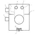
図1は、本発明にかかる遮光フィルムの構成を示す模式的な図である。本発明の遮光フィルムは、基材としての樹脂フィルム1と、その表面に形成されたNi系金属膜2と、その上に形成された低反射性のNi系酸化物膜3から構成されている。そして、その表面粗さが0.1〜0.7μm(算術平均高さRa)、より好ましくは、0.2〜0.7μm、最も好ましくは、0.3〜0.6μmである。0.1μm未満であると低光沢性の点で、また0.7μmを超えると表面欠陥が付きやすいという点で好ましくない。
FIG. 1 is a schematic diagram showing a configuration of a light-shielding film according to the present invention. The light-shielding film of the present invention comprises a
樹脂フィルム1の厚みは、12.5〜125μmの範囲であることが望ましい。12.5μmより薄いものでは、ハンドリングが悪いとフィルムに傷や折れ目などの表面欠陥が付きやすくなり、125μmより厚いと小型化が進む絞り装置や光量調整用装置へ遮光羽根を複数枚搭載することができないからである。
The thickness of the
遮光性のNi系金属膜(金属膜)の膜厚は、特に制限されないが、膜厚を30〜280nm、好ましくは40〜260nm、より好ましくは50〜250nmとすることができる。膜厚が30nm未満であると膜の光通過が生じて十分な遮光機能を持たないので好ましくない。また、膜厚が厚くなると遮光性が良くなるが、280nmを超えると、材料コストや成膜時間の増加による製造コスト高につながり、また膜の応力も大きくなって変形しやすくなる。
低反射性のNi系金属酸化物膜(酸化物膜)は、特に制限されないが、膜厚を5〜250nm、好ましくは20〜240nm、より好ましくは30〜200nmとすることで可視域の反射率を低減することができる。膜厚が5nm未満であると反射率、光沢度を十分に低下できない場合があり、250nmを超えると、表面抵抗が大きくなるだけでなく、経済性の面でも好ましくない。
The film thickness of the light-shielding Ni-based metal film (metal film) is not particularly limited, but the film thickness can be 30 to 280 nm, preferably 40 to 260 nm, more preferably 50 to 250 nm. A film thickness of less than 30 nm is not preferable because light passing through the film occurs and the light shielding function is not sufficient. Further, when the film thickness is increased, the light shielding property is improved. However, if the film thickness exceeds 280 nm, the manufacturing cost is increased due to the increase in material cost and film formation time, and the stress of the film is increased and the film is easily deformed.
The low-reflectivity Ni-based metal oxide film (oxide film) is not particularly limited, but the reflectivity in the visible range can be achieved by setting the film thickness to 5 to 250 nm, preferably 20 to 240 nm, more preferably 30 to 200 nm. Can be reduced. If the film thickness is less than 5 nm, the reflectivity and glossiness may not be sufficiently lowered. If the film thickness exceeds 250 nm, not only the surface resistance increases, but also from the economical viewpoint.
上記Ni系金属膜と低反射性のNi系酸化物膜は、樹脂フィルム基材の片面に形成されていてもよいが、両面に形成されている方が好ましい。両面に形成される場合は、各面の膜の材質が同じで、フィルム基材を中心として対称の構造であることが、より好ましい。フィルム基材の上に形成された薄膜は、基材に対して応力を与えるため、変形の要因となる。応力による変形は成膜直後でも見られる場合があるが、特に200℃程度に加熱されると変形が大きくなり顕著となりやすい。しかし、上記のようにフィルム基材の両面に形成するNi系金属膜と低反射性のNi系酸化物膜の材質を同じにして、基材を中心として対称の構造にすることで、加熱条件下でも応力のバランスが維持され、フラットな耐熱遮光フィルムを実現しやすい。
すなわち、両面に形成されるNi系金属膜(B)同士、及びNi系酸化物膜(C)同士は、それぞれ実質的に同じ金属元素組成であることが好ましい。また、両面に形成されるNi系酸化物のガスバリア膜(D)同士、Ni系金属膜(B)同士、及びNi系酸化物膜(C)同士は、それぞれ実質的に同じ金属元素組成であることが好ましい。
The Ni-based metal film and the low-reflectivity Ni-based oxide film may be formed on one side of the resin film substrate, but are preferably formed on both sides. When formed on both surfaces, it is more preferable that the material of the film on each surface is the same, and the structure is symmetrical about the film substrate. Since the thin film formed on the film base material gives stress to the base material, it causes deformation. Although deformation due to stress may be observed even immediately after film formation, the deformation becomes large and becomes prominent particularly when heated to about 200 ° C. However, as described above, the Ni-based metal film and the low-reflectivity Ni-based oxide film formed on both sides of the film base material are made the same material, and the heating condition Stress balance is maintained even underneath, making it easy to realize a flat heat-resistant light-shielding film.
That is, it is preferable that the Ni-based metal films (B) and the Ni-based oxide films (C) formed on both surfaces have substantially the same metal element composition. Further, the Ni-based oxide gas barrier films (D), Ni-based metal films (B), and Ni-based oxide films (C) formed on both surfaces have substantially the same metal element composition. It is preferable.
(A)樹脂フィルム基材
本発明の耐熱遮光フィルムの基材である樹脂フィルムは、その表面に算術平均高さRaが0.2〜0.8μm、特に0.3〜0.7μmの微細な凹凸構造を有することが必要である。算術平均高さとは、算術平均粗さとも言われ、粗さ曲線からその平均線の方向に基準長さだけ抜き取り、この抜き取り部分の平均線から測定曲線までの偏差の絶対値を合計して平均した値である。Raが0.2μmより小さいと、フィルム表面に形成した金属膜の密着性が得られず、十分な低光沢性や低反射性も得られない。また、Raが0.8μmを超えると、フィルム表面の凹凸が大きすぎて凹部で金属膜の成膜ができず、フィルム表面を被覆し十分な遮光性を得ようとすれば金属膜の膜厚が厚くなってしまうためコスト高となり好ましくない。
(A) Resin film substrate The resin film which is the substrate of the heat-resistant light-shielding film of the present invention has a fine arithmetic average height Ra of 0.2 to 0.8 μm, particularly 0.3 to 0.7 μm on the surface thereof. It is necessary to have an uneven structure. Arithmetic mean height is also called arithmetic mean roughness, and is extracted from the roughness curve by the reference length in the direction of the mean line, and the absolute value of the deviation from the mean line of the extracted part to the measurement curve is summed and averaged. It is the value. When Ra is smaller than 0.2 μm, the adhesion of the metal film formed on the film surface cannot be obtained, and sufficient low glossiness and low reflectivity cannot be obtained. On the other hand, if Ra exceeds 0.8 μm, the unevenness of the film surface is so large that the metal film cannot be formed in the recess, and the film thickness of the metal film can be obtained by covering the film surface and obtaining sufficient light shielding properties. Is undesirably high in cost.
基材として用いる樹脂フィルムは、透明樹脂で構成されていても顔料を練り込んだ着色樹脂で構成されていても構わないが、200℃以上の耐熱性を有するものでなければならない。ここで、200℃以上の耐熱性を有するフィルムとは、ガラス転移点が200℃以上であるフィルムであり、またガラス転移点の存在しない材料については、200℃以上の温度にて変質しないことを意味する。樹脂材料の材質としては量産性を考慮した場合、スパッタリングによるロールコーティングが可能となるような可撓性を有する材料であることが望ましい。 The resin film used as the substrate may be made of a transparent resin or a colored resin kneaded with a pigment, but must have a heat resistance of 200 ° C. or higher. Here, a film having a heat resistance of 200 ° C. or higher is a film having a glass transition point of 200 ° C. or higher, and a material having no glass transition point is not altered at a temperature of 200 ° C. or higher. means. In view of mass productivity, the resin material is preferably a flexible material that enables roll coating by sputtering.
耐熱性の樹脂フィルムには、ポリイミド(PI)、アラミド(PA)、ポリフェニレンサルファイド(PPS)、又はポリエーテルサルフォン(PES)から選択される1種以上の材料で構成されているフィルムが好ましいが、200℃以上の耐熱性を有していればこれらに限定されない。その中でもポリイミドフィルムは、最も耐熱温度が高く、特に好ましいフィルムである。 The heat resistant resin film is preferably a film composed of one or more materials selected from polyimide (PI), aramid (PA), polyphenylene sulfide (PPS), or polyether sulfone (PES). If it has the heat resistance of 200 degreeC or more, it will not be limited to these. Among them, the polyimide film has the highest heat resistant temperature and is a particularly preferable film.
樹脂フィルム表面の凹凸は、フィルム表面を表面処理して形成する。例えば、ショット材を使用したマット処理加工を行って得ることが簡易的な方法であるが、これに限定されない。ナノインプリンティング加工で表面に微細凹凸構造を形成しても得ることができる。また、マット処理の際のショット材には砂などが利用されるが、これに限定されない。マット処理では、フィルムを搬送しながらフィルム表面に凹凸を形成することができるが、最適なRa値の凹凸は、マット処理中のフィルム搬送速度とショット材の種類、大きさに依存するので、これらの条件を最適化してフィルム表面の算術平均高さRa値が0.2〜0.8μmとなるように表面処理を行う。マット処理後のフィルムは、洗浄してショット材を除去した後、乾燥する。フィルムの両面に金属膜と低反射性の酸化物膜を形成する場合は、フィルムの両面をマット処理する。 The unevenness on the surface of the resin film is formed by surface-treating the film surface. For example, although it is a simple method to obtain by carrying out the mat processing using a shot material, it is not limited to this. It can also be obtained by forming a fine relief structure on the surface by nanoimprinting. Further, sand or the like is used as a shot material in the mat processing, but is not limited thereto. In the mat treatment, irregularities can be formed on the film surface while conveying the film, but the irregularities with the optimum Ra value depend on the film conveyance speed during the mat treatment and the type and size of the shot material. The surface treatment is performed so that the arithmetic average height Ra value of the film surface is 0.2 to 0.8 μm. The film after the mat treatment is washed to remove the shot material and then dried. When a metal film and a low-reflective oxide film are formed on both sides of the film, both sides of the film are matted.
(B)金属膜
本発明の耐熱遮光フィルムは、200℃の高熱環境下でも耐えうる耐熱性を有している。それは、スパッタリング法で得た金属膜と低反射性の酸化物膜が高緻密性で耐酸化性が良いことの他、フィルムと金属膜との密着性が良いことによる。
(B) Metal film The heat-resistant light-shielding film of the present invention has heat resistance that can withstand even in a high heat environment of 200 ° C. This is because the metal film obtained by the sputtering method and the low-reflective oxide film have high density and good oxidation resistance, as well as good adhesion between the film and the metal film.
一般に金属膜は酸化されると透明度が増加するため、遮光膜となる金属膜の耐酸化性は重要である。本発明の耐熱遮光フィルムに用いる金属膜の材料は、耐酸化性に優れたニッケル系材料が好ましい。具体的には、前記金属膜は、純粋なニッケルでもよいが、ニッケルを主成分として、チタン、タンタル、タングステン、バナジウム、アルミニウム、及び銅からなる群から選ばれた1種以上の元素が添加されているニッケル系合金膜であることが好ましい。上記元素が添加された金属膜は、純ニッケルに比べて酸化されにくい。
また、前記Ni系金属膜の添加元素は、全構成元素に対して、1〜18原子%、特に5〜14原子%含有されていることが好ましい。1原子%未満であるとニッケルターゲットの強磁性特性を極端に弱めることができなくなり、磁力の弱い通常の磁石を配置したカソードで直流マグネトロンスパッタリング法による成膜を行えなくなる。また、18原子%を超えると多量の金属間化合物を形成し、スパッタリングターゲットの脆性が増し、スパッタリング時の熱応力等で割れてしまい、スパッタリングができなくなる恐れがあるだけでなく、得られる金属合金膜の膜質が悪くなる可能性があるため、好ましくない。
また、ニッケル系ターゲットを用いたスパッタリング成膜での成膜速度は、他の金属ターゲットを用いたスパッタリング成膜と比べて速いことが特徴であり、この面でも生産性に有利である。例えば、ニッケルターゲットを用いた直流スパッタリングによるニッケル膜の成膜速度は、チタンターゲットを用いた同一条件のチタン膜の成膜速度と比べて1.5〜2倍ほど速い。
In general, when a metal film is oxidized, the transparency increases. Therefore, the oxidation resistance of the metal film to be a light shielding film is important. The material of the metal film used for the heat-resistant light-shielding film of the present invention is preferably a nickel-based material having excellent oxidation resistance. Specifically, the metal film may be pure nickel, but one or more elements selected from the group consisting of titanium, tantalum, tungsten, vanadium, aluminum, and copper are added. The nickel-based alloy film is preferable. The metal film to which the above elements are added is less likely to be oxidized than pure nickel.
The additive element of the Ni-based metal film is preferably contained in an amount of 1 to 18 atomic%, particularly 5 to 14 atomic%, based on all constituent elements. If it is less than 1 atomic%, the ferromagnetic properties of the nickel target cannot be extremely weakened, and film formation by the direct current magnetron sputtering method cannot be performed with a cathode on which a normal magnet having a weak magnetic force is disposed. Further, if it exceeds 18 atomic%, a large amount of intermetallic compounds are formed, the brittleness of the sputtering target is increased, cracking due to thermal stress at the time of sputtering, etc., and there is a possibility that sputtering cannot be performed. This is not preferable because the film quality of the film may deteriorate.
Further, the film formation speed in sputtering film formation using a nickel-based target is characterized by being faster than sputtering film formation using other metal targets, and this aspect is also advantageous for productivity. For example, the deposition rate of a nickel film by direct current sputtering using a nickel target is about 1.5 to 2 times faster than the deposition rate of a titanium film under the same conditions using a titanium target.
なお、上記のNi系金属膜には、炭素、窒素が含まれていても構わない。Ni系金属膜への炭素、窒素を導入するには、それぞれ、金属膜を成膜する時のスパッタリングガス中に炭化水素ガス、窒素ガスなどの炭素元素や窒素元素を含む添加ガスを導入してスパッタリング成膜することで可能であるが、上記のような添加ガスを用いなくても、ターゲット中に炭素、窒素を含有させることでも、これらの元素を導入することができる。特にNi系金属膜に炭素、窒素が含まれると耐熱性を更に改善することができるため有用である。よって、本発明の耐熱遮光フィルムの金属膜材料には、上記の方法で作製された炭化ニッケル、窒化ニッケル、炭化窒化ニッケルなどの炭化物や窒化物や炭化窒化物も、十分な遮光性と耐熱性を発揮する金属膜材料であり、樹脂フィルムに対する高密着性も発揮するため含まれる。また、本発明の金属膜には、酸素はなるべく含まないほうが、樹脂フィルムとの高い密着性や高い遮光性を維持するためには好ましい。しかし、スパッタリングガス中に残留する酸素などが成膜時に金属膜の一部、或いは全体に中に取り込まれて含有しても、金属性や高い遮光性や樹脂フィルムとの高い密着性を損なわない程度であれば構わない。金属膜中の酸素の含有量は、樹脂フィルムとの密着性を維持するために、金属元素に対して5原子%以下、特に3原子%以下が望ましい。
また、本発明の耐熱遮光フィルムの金属膜は、組成(金属元素の含有量や種類、炭素含有量、窒素含有量、酸素含有量)の異なった複数種類の金属膜の積層膜で構成されていてもかまわない。
The Ni-based metal film may contain carbon and nitrogen. In order to introduce carbon and nitrogen into the Ni-based metal film, an additive gas containing carbon and nitrogen elements such as hydrocarbon gas and nitrogen gas is introduced into the sputtering gas when forming the metal film, respectively. Although it is possible by performing sputtering film formation, these elements can be introduced even if carbon and nitrogen are contained in the target without using the above additive gas. In particular, if the Ni-based metal film contains carbon and nitrogen, it is useful because the heat resistance can be further improved. Therefore, as the metal film material of the heat-resistant light-shielding film of the present invention, carbides such as nickel carbide, nickel nitride, and nickel carbonitride, nitrides, and carbonitrides produced by the above-described method also have sufficient light shielding properties and heat resistance. Is included because it also exhibits high adhesion to a resin film. In addition, it is preferable that the metal film of the present invention contains as little oxygen as possible in order to maintain high adhesion to the resin film and high light shielding properties. However, even if oxygen or the like remaining in the sputtering gas is incorporated into a part or the whole of the metal film at the time of film formation, it does not impair the metallic property, the high light shielding property, and the high adhesion to the resin film. It doesn't matter as long as it is about. The oxygen content in the metal film is desirably 5 atomic% or less, particularly 3 atomic% or less, based on the metal element in order to maintain adhesion with the resin film.
In addition, the metal film of the heat-resistant light-shielding film of the present invention is composed of a laminated film of a plurality of types of metal films having different compositions (content and type of metal element, carbon content, nitrogen content, oxygen content). It doesn't matter.
密着性については、元来、有機物である樹脂フィルム基材と無機物である金属膜との間では高い密着性を得ることが難しい。これは、樹脂フィルム基材と金属膜の界面の密着性が不十分である場合、200℃の高熱環境下で、樹脂フィルム基材と金属膜の熱膨張差により膜剥離が生じやすいからである。
このような熱膨張差による膜剥離を回避するには、樹脂フィルム基材と膜の高密着性を維持する必要があるが、本発明の金属膜は、チタン、タンタル、タングステン、バナジウム、アルミニウム、及び銅からなる群から選ばれる1種類以上の添加元素を含むニッケル系の金属膜とすることが有効である。樹脂フィルムの表面は、酸素の官能基を有しており、本発明の金属膜中には適量のチタン、タンタル、タングステン、バナジウム、アルミニウム、又は銅などの酸化されやすい元素が含まれており、フィルム表面の酸素の官能基と化学結合が生じて、フィルムと金属膜間の密着性が強化される。
About adhesion, it is difficult to obtain high adhesion between a resin film substrate that is organic and a metal film that is inorganic. This is because when the adhesion at the interface between the resin film substrate and the metal film is insufficient, film peeling is likely to occur due to a difference in thermal expansion between the resin film substrate and the metal film in a high heat environment of 200 ° C. .
In order to avoid such film peeling due to the difference in thermal expansion, it is necessary to maintain high adhesion between the resin film substrate and the film. And a nickel-based metal film containing one or more additive elements selected from the group consisting of copper and copper. The surface of the resin film has an oxygen functional group, and the metal film of the present invention contains an appropriate amount of an easily oxidizable element such as titanium, tantalum, tungsten, vanadium, aluminum, or copper, A chemical bond is formed with a functional group of oxygen on the film surface, and the adhesion between the film and the metal film is enhanced.
(C)酸化物膜
また、本発明の耐熱遮光フィルムは、低反射性の酸化物膜を有している。樹脂フィルム基材に形成された金属膜の反射率は高いが、金属膜の上に低反射性の酸化物膜を積層することで、耐熱遮光フィルムの反射率を減少することができる。低反射性の酸化物膜は、単層でも酸素含有量や添加元素の種類及び添加量の異なる複数層で構成されてもかまわない。また、金属膜上に積層する低反射性の酸化物膜は、透明度の高いものでも、透明度が低くて着色したものでも良い。
(C) Oxide film The heat-resistant light-shielding film of the present invention has a low-reflective oxide film. Although the reflectance of the metal film formed on the resin film substrate is high, the reflectance of the heat-resistant light-shielding film can be reduced by laminating a low-reflection oxide film on the metal film. The low-reflective oxide film may be a single layer or a plurality of layers having different oxygen contents, types of additive elements, and added amounts. The low-reflective oxide film laminated on the metal film may be either highly transparent or colored with low transparency.
本発明の低反射性の酸化物膜は、ニッケルを主成分とした酸化物膜であることが好ましい。ニッケルを主成分とした酸化物膜は、高熱環境下での耐熱性や耐食性に優れていることと、ニッケルを主成分とする下地の金属膜と金属成分が同じであることから金属膜との密着性が良いからである。
具体的には、前記酸化物膜は、金属成分がニッケルのみからなるニッケル酸化物であってもよいが、ニッケルを主成分とし、さらに、チタン、タンタル、タングステン、バナジウム、アルミニウム、及び銅からなる群から選ばれた少なくとも1種類以上の元素を1〜18原子%、特に5〜14原子%添加した酸化物膜であることが好ましい。
The low reflective oxide film of the present invention is preferably an oxide film containing nickel as a main component. The oxide film mainly composed of nickel has excellent heat resistance and corrosion resistance under high heat environment, and the metal component is the same as that of the underlying metal film mainly composed of nickel. This is because the adhesion is good.
Specifically, the oxide film may be a nickel oxide whose metal component is composed only of nickel, but is mainly composed of nickel and further composed of titanium, tantalum, tungsten, vanadium, aluminum, and copper. An oxide film to which at least one element selected from the group is added in an amount of 1 to 18 atomic%, particularly 5 to 14 atomic% is preferable.
Ni系酸化物膜の材料は、金属成分が金属膜と同じでなくともよいが、金属膜と同じ成分の酸化物膜とすることが望ましい。これにより、単一のスパッタリングターゲットを用いて、金属膜と低反射性の酸化物膜の両方を成膜することができ、単一のカソードを有するスパッタリング装置で製造することができ、製造コストを低減することができる。上記ニッケルを主成分とした酸化物膜の膜厚は、特に制限されないが、膜厚を5〜240nmとすることで可視域の反射率を低減することができる。 The material of the Ni-based oxide film may not be the same as that of the metal film, but is preferably an oxide film having the same component as that of the metal film. As a result, both a metal film and a low-reflective oxide film can be formed using a single sputtering target, and can be manufactured with a sputtering apparatus having a single cathode. Can be reduced. The thickness of the oxide film containing nickel as a main component is not particularly limited, but the reflectance in the visible region can be reduced by setting the thickness to 5 to 240 nm.
前記Ni系酸化物膜には、上記の金属元素の他、炭素、窒素が含まれていても構わない。Ni系酸化物膜に炭素、窒素を含ませると屈折率を調整することができて低反射性を実現しやすくなる。また、前記酸化物膜には、酸素欠損を多く含む金属酸化物膜のように可視域で透過率の低い(例えば単膜で透過率が10〜60%)膜を採用すると、例えば波長380〜780nmにおける反射率が2%以下の著しい低反射性を実現して黒色を呈した耐熱遮光フィルムを得ることができる。このような低反射の黒色のフィルムは、液晶プロジェクターのレンズユニット側やデジタル撮影機器の撮像素子側の部材として利用する場合に特に好ましい。レンズユニット側や撮像素子側では部材による反射光が強いと迷光となって悪影響を及ぼすからである。前記Ni系酸化物膜には、組成(酸素含有量、炭素含有量、窒素含有量、金属元素の含有量や種類)の異なった複数種類の酸化物膜の積層膜で構成されていてもかまわない。組成が異なって屈折率と消衰係数の異なった酸化物膜の積層膜を用いることで、より強い反射防止効果が発現して低反射性を実現することもできる。 The Ni-based oxide film may contain carbon and nitrogen in addition to the above metal elements. When carbon and nitrogen are included in the Ni-based oxide film, the refractive index can be adjusted and low reflectivity can be easily realized. Further, when a film having a low transmittance in the visible region (for example, a single film having a transmittance of 10 to 60%) such as a metal oxide film containing many oxygen vacancies is employed as the oxide film, for example, a wavelength of 380 to 380 It is possible to obtain a heat-resistant light-shielding film exhibiting a black color by realizing a remarkably low reflectivity with a reflectance at 780 nm of 2% or less. Such a low-reflection black film is particularly preferable when used as a member on the lens unit side of a liquid crystal projector or the image sensor side of a digital photographing device. This is because if the reflected light from the member is strong on the lens unit side or the image pickup device side, it becomes stray light and has an adverse effect. The Ni-based oxide film may be composed of a laminated film of a plurality of types of oxide films having different compositions (oxygen content, carbon content, nitrogen content, metal element content and type). Absent. By using a laminated film of oxide films having different compositions and different refractive indexes and extinction coefficients, a stronger antireflection effect is exhibited and low reflectivity can be realized.
上記酸化物膜の膜厚は、特に制限されないが、膜厚を5〜240nmとすることで可視域の反射率を低減することができる。膜厚が5nm未満であると反射率、光沢度を十分に低下できない場合があり、240nmを超えると表面抵抗が大きくなるだけでなく、経済性の面でも好ましくない。 The thickness of the oxide film is not particularly limited, but the reflectance in the visible region can be reduced by setting the thickness to 5 to 240 nm. If the film thickness is less than 5 nm, the reflectance and glossiness may not be sufficiently lowered. If the film thickness exceeds 240 nm, not only the surface resistance increases, but it is also not economical.
また、本発明の耐熱遮光フィルムは、熱線光の照射による温度上昇をなるべく回避させるために、熱線光の高反射特性を持たせることも可能である。この場合、前記酸化物膜には、上記とは逆に、可視域〜近赤外域の透過率がなるべく高い酸化物材質を使用して、酸化物膜内での熱線の吸収をなるべく抑制し、金属膜による熱線の高反射特性を利用するのである。また、そのような酸化物膜の屈折率を加味して、酸化物膜の膜厚を最適化し、酸化物膜/金属膜界面での近赤外の反射光と、外界/酸化物界面での近赤外の反射光が強め合って、高反射特性を実現させるとより好ましい。以上のような構成の熱線の高反射特性を持たせた耐熱遮光フィルムは、可視域での最大反射率が3〜7%と適度な反射率を示すことができる。反射率が高く10%以上であると、反射光が迷光となり悪影響を及ぼすため、7%以下が好ましい。このような構成の耐熱遮光フィルムは、黒色度は劣るが、反射光の波長バランスに応じて、赤色、紫色、青色、黄土色などを呈する。
また、樹脂フィルムの両面に金属膜と酸化物膜を積層されている本発明の耐熱遮光フィルムにおいて、黒色度と反射率が両面で異なった構成をとることも、用途によっては有効である。例えば、本発明の耐熱遮光フィルムをプロジェクター用のランプに近い場所での羽根材として用いる場合には、ランプ光の照射される面側は、熱線光による加熱の回避を最重要視して、可視〜近赤外光の高反射特性を有する黒色度の低い構成として、ランプ側と逆面は可視光の反射が迷光となって嫌うために、可視域の低反射性を有する黒色度の高い構成とすることも有効である。その場合、上述したように、ランプ側は酸素欠損が少なくて透過率の高いNi系酸化物膜が用いられ、その反対側には酸素欠損が多くて可視域の透過率の低いNi系酸化物膜を用いる。
In addition, the heat-resistant light-shielding film of the present invention can have a high reflection property of heat ray light in order to avoid as much as possible a temperature rise due to heat ray light irradiation. In this case, contrary to the above, the oxide film uses an oxide material having as high a transmittance as possible in the visible region to the near infrared region, and suppresses the absorption of heat rays in the oxide film as much as possible. The high reflection characteristic of the heat ray by the metal film is used. In addition, taking into account the refractive index of such an oxide film, the thickness of the oxide film is optimized, and the near-infrared reflected light at the oxide film / metal film interface and It is more preferable that near-infrared reflected light strengthen each other to realize high reflection characteristics. The heat-resistant light-shielding film having the high-reflective property of the heat ray having the above-described configuration can exhibit an appropriate reflectivity of 3 to 7% in the maximum reflectivity in the visible range. When the reflectance is high and 10% or more, the reflected light becomes stray light and has an adverse effect, so 7% or less is preferable. The heat-resistant light-shielding film having such a configuration is inferior in blackness, but exhibits red, purple, blue, ocher, etc. according to the wavelength balance of reflected light.
In addition, in the heat-resistant light-shielding film of the present invention in which a metal film and an oxide film are laminated on both surfaces of a resin film, it is also effective depending on the application to have a structure in which the blackness and the reflectance are different on both surfaces. For example, when the heat-resistant light-shielding film of the present invention is used as a blade material in a place close to a projector lamp, the surface side irradiated with the lamp light is visible with the highest priority on avoiding heating by heat ray light. ~ As a low blackness configuration with high near infrared light reflection characteristics, the opposite side of the lamp side dislikes the reflection of visible light as stray light. It is also effective. In that case, as described above, a Ni-based oxide film having a low oxygen deficiency and a high transmittance is used on the lamp side, and a Ni-based oxide film having a large amount of oxygen deficiency and a low transmittance in the visible region is used on the opposite side. Use a membrane.
導電性については、プラスチックフィルムを用いた場合は絶縁性のため静電気が発生しやすく、遮光羽根として動作した時に静電気が発生し、羽根同士がくっつかないために重要である。
本発明の耐熱遮光フィルムに用いる金属膜及び酸化物膜の材料は、導電性に優れたニッケル系材料が好ましい。具体的な金属膜及び酸化物膜としては、金属成分が純粋なニッケルでもよいが、ニッケルを主成分として、チタン、タンタル、タングステン、バナジウム、アルミニウム、及び銅からなる群から選ばれた1種類以上の元素が添加されているニッケル系合金膜(複合金属酸化物膜)であることが好ましい。上記元素が添加されることで、添加元素が半導体でのドーパント的な作用を有し、電気抵抗を減少することができる。最表面が酸化珪素、アルミナなどの絶縁膜で形成される遮光フィルムでは、表面抵抗値は104Ω/□程度が限界であるが、本発明の耐熱遮光フィルムでは表面抵抗値を1000Ω/□以下、好ましくは500Ω/□以下、更には100Ω/□以下にすることができる。
Concerning conductivity, it is important that when a plastic film is used, static electricity is likely to be generated due to insulation, and static electricity is generated when operated as a light shielding blade, and the blades do not stick to each other.
The material of the metal film and oxide film used for the heat-resistant light-shielding film of the present invention is preferably a nickel-based material having excellent conductivity. As the specific metal film and oxide film, the metal component may be pure nickel, but one or more kinds selected from the group consisting of titanium, tantalum, tungsten, vanadium, aluminum, and copper having nickel as a main component. A nickel-based alloy film (composite metal oxide film) to which these elements are added is preferable. By adding the above elements, the added elements have a dopant-like action in a semiconductor, and electrical resistance can be reduced. In the light shielding film whose outermost surface is formed of an insulating film such as silicon oxide or alumina, the surface resistance value is limited to about 10 4 Ω / □, but in the heat resistant light shielding film of the present invention, the surface resistance value is 1000Ω / □ or less. , Preferably 500Ω / □ or less, and more preferably 100Ω / □ or less.
なお、本発明の耐熱遮光フィルムは、上記酸化物膜の表面に、潤滑性や低摩擦性を有する他の薄膜(例えば、フッ素含有の有機膜や、炭素膜、ダイヤモンドライクカーボン膜など)を薄く塗布して利用しても、本発明の特徴を損なわなければ構わない。 In the heat-resistant light-shielding film of the present invention, other thin films (for example, fluorine-containing organic films, carbon films, diamond-like carbon films, etc.) having lubricity and low friction properties are thinly formed on the surface of the oxide film. Even if it is applied and used, it does not matter if the characteristics of the present invention are not impaired.
(D)ガスバリア膜
通常、ポリイミドなどの樹脂フィルム基材には、酸素や水分が多く含まれる。ポリイミド中のこれらのガスは、成膜前に加熱処理等を行って除去する。しかし、十分に除去できずに、金属膜と酸化物膜を形成して製造された耐熱遮光フィルムは、250℃前後の高温環境下におかれると、樹脂フィルムから酸素や水分が放出されて金属膜内の一部に酸素が進入する。酸素が進入した金属膜は光学定数が異なるため、耐熱遮光フィルムの色味の変化が生じてしまう。また、成膜前に十分にガス抜きを行って製造された耐熱遮光フィルムでも、恒温恒湿試験(例えば、85℃、90%RH、1000時間)の環境下に耐熱遮光フィルムを配置すると、樹脂フィルムの側面から水や酸素が進入して、金属膜の樹脂フィルム側の一部に酸素が進入して、同様の要因で色味が変わってしまう。このような色味変化を回避するため、本発明では、樹脂フィルム基材と前記金属膜の界面に、ガスバリア膜として金属酸化物膜をスパッタリング法で形成することが好ましい。
(D) Gas barrier film Usually, a resin film substrate such as polyimide contains a large amount of oxygen and moisture. These gases in the polyimide are removed by heat treatment or the like before film formation. However, a heat-resistant light-shielding film manufactured by forming a metal film and an oxide film without being sufficiently removed can release oxygen and moisture from the resin film when placed in a high temperature environment of around 250 ° C. Oxygen enters part of the membrane. Since the metal film into which oxygen has entered has different optical constants, the color of the heat-resistant light-shielding film changes. In addition, even in a heat-resistant light-shielding film manufactured by sufficiently venting before film formation, if the heat-resistant light-shielding film is placed in an environment of a constant temperature and humidity test (eg, 85 ° C., 90% RH, 1000 hours) Water and oxygen enter from the side of the film, oxygen enters a part of the metal film on the resin film side, and the color changes due to the same factors. In order to avoid such color change, in the present invention, it is preferable to form a metal oxide film as a gas barrier film by a sputtering method at the interface between the resin film substrate and the metal film.
ガスバリア膜は、酸化物膜(C)と同じ組成のニッケル系酸化物膜の他、例えば、チタン、タンタル、タングステン、バナジウム、モリブデン、モリブデン、コバルト、二オブ、鉄、アルミニウム、及び珪素からなる群より選ばれる1種類以上の元素を主成分とするニッケルを含まない酸化物膜も有効である。これらのガスバリア膜は、化学量論組成よりも酸素欠損を有する膜の方が、膜の緻密性が高いため、フィルムから放出されるガスの通過を、より効果的に阻止できる。 In addition to the nickel-based oxide film having the same composition as the oxide film (C), the gas barrier film is, for example, a group consisting of titanium, tantalum, tungsten, vanadium, molybdenum, molybdenum, cobalt, niobium, iron, aluminum, and silicon. An oxide film that does not contain nickel and contains one or more selected elements as a main component is also effective. Among these gas barrier films, a film having oxygen vacancies has a higher film density than a stoichiometric composition, so that the passage of gas released from the film can be more effectively prevented.
ガスバリア膜は5〜30nm、好ましくは8〜25nm形成されていることが望ましい。膜厚が5nm未満ではガスバリア機能が不十分であり、30nmを超えると、金属膜との密着性が低下することがあり好ましくない。ガスバリア膜(D)、金属膜(B)、及び酸化物膜(C)が同一のNi系金属ターゲットから製造できる膜であると、単一のターゲットと単一のカソードを用いて耐熱遮光フィルムを製造できるため製造コストの低減につながるため好ましい。 The gas barrier film is desirably formed to 5 to 30 nm, preferably 8 to 25 nm. If the film thickness is less than 5 nm, the gas barrier function is insufficient, and if it exceeds 30 nm, the adhesion to the metal film may be lowered, which is not preferable. When the gas barrier film (D), the metal film (B), and the oxide film (C) are films that can be manufactured from the same Ni-based metal target, a heat resistant light-shielding film is formed using a single target and a single cathode. Since it can manufacture, it leads to the reduction of manufacturing cost, and is preferable.
2.耐熱遮光フィルムの製造方法
本発明の耐熱遮光フィルムの製造方法は、算術平均高さRaが0.2〜0.8μmの表面粗さを有する樹脂フィルム基材(A)をスパッタリング装置に供給し、不活性ガス雰囲気下でスパッタリングして、樹脂フィルム基材(A)上にNi系金属膜(B)を形成し、次に、不活性ガス雰囲気に酸素ガスを導入しながらスパッタリングして、Ni系金属膜(B)上にNi系酸化物膜(C)を形成して耐熱遮光フィルムを得ることを特徴とする。
2. Manufacturing method of heat-resistant light-shielding film The manufacturing method of the heat-resistant light-shielding film of the present invention supplies a resin film substrate (A) having a surface roughness with an arithmetic average height Ra of 0.2 to 0.8 μm to a sputtering apparatus, Sputtering is performed under an inert gas atmosphere to form a Ni-based metal film (B) on the resin film substrate (A), and then sputtering while introducing an oxygen gas into the inert gas atmosphere. A heat resistant light-shielding film is obtained by forming a Ni-based oxide film (C) on the metal film (B).
本発明の耐熱遮光フィルムは、上記樹脂フィルム基材の表面に、スパッタリング法でNi系金属膜が形成され、該Ni系金属膜上に、反射防止効果を有するNi系酸化物膜がスパッタリングで形成されている。本発明では、Ni系金属膜および低反射性のNi系酸化物膜がスパッタリング法で形成されているため、インクの塗布法や真空蒸着法と比べて膜の緻密性がよく、下地(基板や膜)との密着性が良好であるという特徴がある。
この性質は、耐熱遮光フィルムを200℃の高熱環境下で使用したときに顕著である。インクの塗布法や真空蒸着法で形成したときは、膜剥がれや、膜の酸化による色味の変化が見られるが、本発明のようにスパッタリング法で膜を形成した場合はこのような恐れがない。
In the heat-resistant light-shielding film of the present invention, a Ni-based metal film is formed on the surface of the resin film substrate by sputtering, and a Ni-based oxide film having an antireflection effect is formed on the Ni-based metal film by sputtering. Has been. In the present invention, since the Ni-based metal film and the low-reflectivity Ni-based oxide film are formed by the sputtering method, the film is denser than the ink coating method or the vacuum deposition method, and the base (substrate or There is a feature that the adhesiveness to the film is good.
This property is remarkable when the heat-resistant light-shielding film is used in a high heat environment of 200 ° C. When formed by ink coating or vacuum deposition, film peeling and color change due to oxidation of the film can be seen, but such a fear may occur when the film is formed by sputtering as in the present invention. Absent.
本発明において、耐熱遮光フィルムは、上述のようにスパッタリング法で樹脂フィルム基材上に金属膜と低反射性の酸化物膜を形成して製造される。スパッタリング法は、蒸気圧の低い材料の膜を基材上に形成する場合や精密な膜厚制御が必要となる時に有効な薄膜形成方法である。一般的に、約10Pa以下のアルゴンガス圧のもとで、基材を陽極とし、膜の原料となるスパッタリングターゲットを陰極として、この間にグロー放電を起こさせてアルゴンプラズマを発生させ、プラズマ中のアルゴン陽イオンを陰極のスパッタリングターゲットに衝突させてスパッタリングターゲット成分の粒子を弾き飛ばし、この粒子を基材上に堆積させて成膜する方法である。 In the present invention, the heat-resistant light-shielding film is produced by forming a metal film and a low-reflective oxide film on a resin film substrate by sputtering as described above. The sputtering method is an effective thin film forming method when a film of a material having a low vapor pressure is formed on a substrate or when precise film thickness control is required. In general, under an argon gas pressure of about 10 Pa or less, a base material is used as an anode, a sputtering target as a film material is used as a cathode, glow discharge is generated therebetween, and argon plasma is generated. In this method, an argon cation collides with a sputtering target serving as a cathode to blow off particles of the sputtering target component and deposit the particles on a substrate to form a film.
スパッタリング法は、アルゴンプラズマの発生方法で分けられ、高周波プラズマを用いるものは高周波スパッタリング法、直流プラズマを用いるものは直流スパッタリング法である。また、マグネトロンスパッタリング法は、スパッタリングターゲットの裏側に磁石を配置し、アルゴンプラズマをスパッタリングターゲット直上に集中させ、低ガス圧でもアルゴンイオンの衝突効率を上げて成膜する方法である。 Sputtering methods are classified according to the method of generating argon plasma. Those using high-frequency plasma are high-frequency sputtering methods, and those using DC plasma are DC sputtering methods. The magnetron sputtering method is a method in which a magnet is arranged on the back side of a sputtering target, argon plasma is concentrated directly on the sputtering target, and a film is formed by increasing the collision efficiency of argon ions even at a low gas pressure.
金属膜と酸化物膜を成膜するには、例えば、図2に示した巻き取り式スパッタリング装置を用いることができる。この装置は、ロール状の樹脂フィルム基材1が巻き出しロール4にセットされ、ターボ分子ポンプ等の真空ポンプ5で真空槽6内を排気した後、巻き出しロール4から搬出されたフィルム1が途中、冷却キャンロール7の表面を通って、巻き取りロール8で巻き取られていく構成をとる。冷却キャンロール7の表面の対向側にはマグネトロンカソード9が設置され、このカソードには膜の原料となるターゲット10が取り付けてある。なお、巻き出しロール4、冷却キャンロール7、巻き取りロール8などで構成されるフィルム搬送部は、隔壁11でマグネトロンカソード9と隔離されている。
In order to form the metal film and the oxide film, for example, a winding type sputtering apparatus shown in FIG. 2 can be used. In this apparatus, a roll-shaped
まず、ロール状の樹脂フィルム基材1を巻き出しロール4にセットし、ターボ分子ポンプ等の真空ポンプ5で真空槽6内を排気する。その後、巻き出しロール4から樹脂フィルム基材1を供給し、途中、冷却キャンロール7の表面を通って、巻き取りロール8で巻き取られていくようにしながら、冷却キャンロール7とカソード間で放電させて、冷却キャンロール表面に密着搬送されている樹脂フィルム基材1に成膜する。なお、樹脂フィルム基材は、スパッタリング前に200℃以上の温度で加熱し、乾燥しておくことが望ましい。
First, the roll-shaped
本発明の耐熱遮光フィルムにおいて、金属膜層は、例えばアルゴン雰囲気中においてNi金属又はNi系合金のスパッタリングターゲットを使用した直流マグネトロンスパッタリング法により樹脂フィルム基材上に成膜形成される。
純ニッケル材は、通常、強磁性体であるため上記金属膜層を直流マグネトロンスパッタリング法で成膜する場合、スパッタリングターゲットと基材間のプラズマに作用するためのスパッタリングターゲット裏面に配置した磁石からの磁力がニッケルターゲット材で遮蔽されて表面に漏洩する磁界が弱くなり、プラズマを集中させて効率よく成膜することが困難となる。これを回避するためには、スパッタリングターゲット裏側に配置する磁石の磁力を強くしたカソードを用い、ニッケルスパッタリングターゲットを通過する磁界を強めてスパッタリングし成膜することが望ましい。
ただし、このような方法を採った場合でも生産時には以下に述べるような別の問題が生じる。すなわち、ニッケルターゲットの連続使用に伴ってスパッタリングターゲットの厚みが減少していくと、スパッタリングターゲットの厚みが薄くなった部分では、プラズマ空間の漏洩磁界が強くなっていく。プラズマ空間の漏洩磁界が強くなると、放電特性が変化して成膜速度が変化する。つまり、生産時に同一のニッケルターゲットを連続して長時間使用するとニッケルターゲットの消耗に伴い、ニッケル膜の成膜速度が変化する問題が生じる。
In the heat-resistant light-shielding film of the present invention, the metal film layer is formed on the resin film substrate by a direct current magnetron sputtering method using a sputtering target of Ni metal or Ni-based alloy, for example, in an argon atmosphere.
Since pure nickel material is usually a ferromagnetic material, when the metal film layer is formed by DC magnetron sputtering, it is from a magnet placed on the back surface of the sputtering target for acting on the plasma between the sputtering target and the substrate. The magnetic field is shielded by the nickel target material and the magnetic field leaking to the surface becomes weak, and it becomes difficult to concentrate the plasma and efficiently form a film. In order to avoid this, it is desirable to use a cathode in which the magnetic force of a magnet arranged on the back side of the sputtering target is increased and to increase the magnetic field passing through the nickel sputtering target to perform sputtering and form a film.
However, even when such a method is adopted, another problem as described below occurs during production. That is, when the thickness of the sputtering target decreases with continuous use of the nickel target, the leakage magnetic field in the plasma space becomes stronger in the portion where the thickness of the sputtering target is reduced. When the leakage magnetic field in the plasma space becomes strong, the discharge characteristics change and the film formation rate changes. That is, if the same nickel target is continuously used for a long time during production, there arises a problem that the deposition rate of the nickel film changes as the nickel target is consumed.
そこで、このような場合は、ニッケルを主成分としてチタン、タンタル、タングステン、バナジウム、アルミニウム、銅から選択された1種類以上の元素が添加されたNi系合金材料をターゲットとすることにより、強磁性が弱められ、上記問題を回避することができ、上記組成の金属合金膜として成膜することができる。本発明においては、ターゲットとして、添加元素含有量を1〜18原子%の範囲で含むNi系合金材料を用いることが望ましい。添加元素含有量を上記のように規定する理由は、1原子%以上含有させることで強磁性特性を極端に弱めることができ、磁力の弱い通常の磁石を配置したカソードでも直流マグネトロンスパッタリングによる成膜を行うことができるからである。また、スパッタリングターゲットによる磁界の遮蔽能力が低いため、スパッタリングターゲットの消耗に依存するプラズマ空間の漏洩磁界の変化も小さく、一定の成膜速度で安定的な成膜が可能となるからである。また、添加元素含有量を18原子%以下とする理由は、添加元素が18原子%を超えて含まれる場合は、多量の金属間化合物を形成し、スパッタリングターゲットの脆性が増し、スパッタリング時の熱応力等で割れてしまい、スパッタリングができなくなる恐れがあり、また、スパッタリングされて得られた金属合金膜の膜質が悪くなる可能性があるためである。 Therefore, in such a case, by using nickel-based alloy material with nickel as a main component and one or more elements selected from titanium, tantalum, tungsten, vanadium, aluminum, and copper added, the target becomes ferromagnetic. Is weakened, the above problem can be avoided, and a metal alloy film having the above composition can be formed. In the present invention, it is desirable to use a Ni-based alloy material containing an additive element content in the range of 1 to 18 atomic% as a target. The reason for prescribing the content of the additive element as described above is that the content of 1 atomic% or more can extremely weaken the ferromagnetic properties, and even a cathode having a weak magnetic force disposed thereon is formed by direct current magnetron sputtering. It is because it can be performed. In addition, since the shielding capability of the magnetic field by the sputtering target is low, the change in the leakage magnetic field in the plasma space depending on the consumption of the sputtering target is small, and stable film formation is possible at a constant film formation rate. The reason why the additive element content is 18 atomic% or less is that when the additive element exceeds 18 atomic%, a large amount of intermetallic compounds are formed, the brittleness of the sputtering target is increased, and the heat during sputtering is increased. This is because there is a possibility that sputtering may be impossible due to stress or the like, and the quality of the metal alloy film obtained by sputtering may be deteriorated.
金属膜を成膜する時の成膜時のガス圧は、装置の種類などによっても異なるので一概に規定できないが、1.0Pa以下、例えば、0.2〜1.0Paにすることが好ましい。これにより、ショット材が樹脂フィルム基材上に微量残存していても、200℃の高熱環境下でショット材、金属膜、低反射性の酸化物膜の熱膨張差によっても膜が剥がれなくなる。成膜時のガス圧が0.2Pa未満であると、ガス圧が低いためスパッタリング法でのアルゴンプラズマが不安定となり、成膜した膜の膜質が悪くなる。また、成膜時のガス圧が1.0Paを超えた場合では、金属膜の粒が粗くなり、高緻密な膜質でなくなるので樹脂フィルム基材との密着力が弱くなり、膜が剥がれてしまう。また、成膜時のフィルム温度は、少なくとも180℃以上とすることが望ましい。これにより200℃以上の耐熱性を有するフィルムとの密着性の優れた、緻密な膜質の耐熱遮光フィルムが得られる。金属膜の膜厚は、成膜時のフィルムの搬送速度とターゲットへの投入電力で制御される。 The gas pressure at the time of forming the metal film varies depending on the type of the apparatus and cannot be generally specified, but is preferably 1.0 Pa or less, for example, 0.2 to 1.0 Pa. As a result, even if a small amount of shot material remains on the resin film substrate, the film does not peel off due to a difference in thermal expansion of the shot material, the metal film, and the low-reflective oxide film in a high heat environment at 200 ° C. If the gas pressure at the time of film formation is less than 0.2 Pa, the gas pressure is low, so that the argon plasma in the sputtering method becomes unstable, and the film quality of the formed film deteriorates. In addition, when the gas pressure during film formation exceeds 1.0 Pa, the metal film grains become coarse and the film quality is not high, so that the adhesion with the resin film substrate is weakened and the film is peeled off. . The film temperature during film formation is preferably at least 180 ° C. or higher. Thereby, a dense heat-resistant light-shielding film having excellent adhesion to a film having a heat resistance of 200 ° C. or higher is obtained. The film thickness of the metal film is controlled by the film conveyance speed during film formation and the input power to the target.
また、成膜中に樹脂フィルム基材はプラズマから自然加熱される。ガス圧とターゲットへの投入電力やフィルム搬送速度を調整することで、ターゲットから基材に入射する熱電子やプラズマからの熱輻射によって成膜中のフィルム基板の表面温度を180℃以上に維持することは容易である。ガス圧は低いほど、投入電力は高いほど、フィルム搬送速度は遅いほどプラズマからの自然加熱による加熱効果は高くなる。成膜時のフィルムが冷却キャンに接触させている場合でも、自然加熱の影響でフィルム表面の温度は冷却キャン温度よりもはるかに高い温度となる。しかし、自然加熱によるフィルム表面の温度は冷却キャンで冷却されながら行われるため、キャンの温度にも大きく依存し、なるべく成膜時の自然加熱の効果を利用するのであれば、冷却キャンの温度を高めにして搬送速度を遅くすることが効果的である。
また、冷却キャンでフィルムが冷却されずにスパッタリング成膜される成膜方法(フローティング法)を採用すると、自然加熱効果を有効に利用することができる。この方法では、ターゲット対向のフィルム基材は背後で冷却されず、成膜室内でフローティングの状態で成膜が行われる。ターゲットやプラズマから熱がフィルムに照射されるが、成膜室は真空であるため、溜まった熱は逃げにくく、効果的に加熱される。フローティング法では、実際270℃以上の自然加熱効果も容易に実現可能である。
成膜中の基材表面の温度は、放射温度計で測定することも可能であり、また予めフィルム表面にサーモラベルを貼り付けておいて、成膜後にラベルの色の変化を見て達した温度を知ることができる。
Further, the resin film substrate is naturally heated from the plasma during film formation. By adjusting the gas pressure, the input power to the target, and the film conveyance speed, the surface temperature of the film substrate during film formation is maintained at 180 ° C. or higher by thermionic radiation incident on the base material from the target and thermal radiation from the plasma. It is easy. The lower the gas pressure, the higher the input power, and the slower the film conveyance speed, the higher the heating effect by natural heating from the plasma. Even when the film during film formation is in contact with the cooling can, the temperature of the film surface is much higher than the cooling can temperature due to the effect of natural heating. However, since the temperature of the film surface by natural heating is performed while being cooled by a cooling can, it greatly depends on the temperature of the can, and if the effect of natural heating at the time of film formation is used as much as possible, the temperature of the cooling can should be set. It is effective to increase the speed and reduce the conveying speed.
In addition, when a film formation method (floating method) in which a film is formed by sputtering without cooling the film with a cooling can, a natural heating effect can be effectively used. In this method, the film substrate facing the target is not cooled behind, but is formed in a floating state in the film formation chamber. Although heat is applied to the film from the target and plasma, since the film formation chamber is vacuum, the accumulated heat is difficult to escape and is effectively heated. In the floating method, a natural heating effect of 270 ° C. or more can be easily realized.
The temperature of the substrate surface during film formation can be measured with a radiation thermometer, and a thermo label was attached to the film surface in advance, and the color change of the label was observed after film formation. You can know the temperature.
前記の通り、通常、ポリイミドなどの樹脂フィルム基材には、酸素や水分が多く含まれるので、本発明では、樹脂フィルム基材に前記金属膜を形成する前に、ガスバリア膜として金属酸化物膜をスパッタリング法で形成することが好ましい。ガスバリア膜は、前記酸化物膜(C)と同じ組成のニッケル系酸化物膜の他、例えば、チタン、タンタル、タングステン、バナジウム、モリブデン、モリブデン、コバルト、二オブ、鉄、アルミニウム、及び珪素からなる群より選ばれる1種類以上の元素を主成分とするニッケルを含まない酸化物膜も有効である。 As described above, since a resin film substrate such as polyimide usually contains a large amount of oxygen and moisture, in the present invention, before forming the metal film on the resin film substrate, a metal oxide film is used as a gas barrier film. Is preferably formed by sputtering. The gas barrier film is made of, for example, titanium, tantalum, tungsten, vanadium, molybdenum, molybdenum, cobalt, niobium, iron, aluminum, and silicon in addition to the nickel-based oxide film having the same composition as the oxide film (C). An oxide film that does not contain nickel and contains one or more elements selected from the group as a main component is also effective.
ガスバリアとしての酸化物層は、例えばアルゴン及び酸素ガス雰囲気中でNi金属又はNi系合金のスパッタリングターゲットを直流マグネトロンスパッタリング法により形成される。酸化物膜を成膜する時の成膜時のガス圧は、装置の種類などによっても異なるので一概に規定できないが、1.0Pa以下、例えば、0.2〜1.0Paにすることが好ましい。成膜時のガス圧が0.2Pa未満であると、ガス圧が低いためスパッタリング法でのアルゴンプラズマが不安定となり、成膜した膜の膜質が悪くなる。また、成膜時のガス圧が1.0Paを超えた場合では、酸化物膜の粒が粗くなり、高緻密な膜質でなくなるので金属膜との密着力が弱くなり、膜が剥がれてしまう。また、成膜時のフィルム温度は、少なくとも180℃以上とすることが望ましい。これにより緻密な酸化物膜を有する耐熱遮光フィルムが得られる。酸化物膜の膜厚は、成膜時のフィルムの搬送速度とターゲットへの投入電力で制御される。これらのガスバリア膜は、5〜30nm形成すると効果的である。 The oxide layer as a gas barrier is formed by a direct current magnetron sputtering method using a sputtering target of Ni metal or Ni-based alloy in an atmosphere of argon and oxygen gas, for example. The gas pressure at the time of forming the oxide film varies depending on the type of apparatus and the like, and thus cannot be generally specified, but is preferably 1.0 Pa or less, for example, 0.2 to 1.0 Pa. . If the gas pressure at the time of film formation is less than 0.2 Pa, the gas pressure is low, so that the argon plasma in the sputtering method becomes unstable, and the film quality of the formed film deteriorates. Further, when the gas pressure during film formation exceeds 1.0 Pa, the oxide film grains become coarse and the film quality is not high, so that the adhesion with the metal film is weakened and the film is peeled off. The film temperature during film formation is preferably at least 180 ° C. or higher. Thereby, a heat-resistant light-shielding film having a dense oxide film is obtained. The film thickness of the oxide film is controlled by the film conveyance speed during film formation and the input power to the target. It is effective to form these gas barrier films with a thickness of 5 to 30 nm.
樹脂フィルム基材(A)は、必要によりガスバリア膜(D)が形成され、金属膜(B)が成膜された後、この金属膜上にNi系酸化物膜(C)を形成する。低反射性の酸化物層は、例えばアルゴン及び酸素ガス雰囲気中でNi金属又はNi系合金のスパッタリングターゲットを直流マグネトロンスパッタリング法により形成される。酸化物膜を成膜する時の成膜時のガス圧は、装置の種類などによっても異なるので一概に規定できないが、1.0Pa以下、例えば、0.2〜1.0Paにすることが好ましい。成膜時のガス圧が0.2Pa未満であると、ガス圧が低いためスパッタリング法でのアルゴンプラズマが不安定となり、成膜した膜の膜質が悪くなる。また、成膜時のガス圧が1.0Paを超えた場合では、酸化物膜の粒が粗くなり、高緻密な膜質でなくなるので金属膜との密着力が弱くなり、膜が剥がれてしまう。また、成膜時のフィルム温度は、少なくとも180℃以上とすることが望ましい。これにより緻密な酸化物膜を有する耐熱遮光フィルムが得られる。酸化物膜の膜厚は、成膜時のフィルムの搬送速度とターゲットへの投入電力で制御される。 The resin film substrate (A) is formed with a gas barrier film (D) if necessary, and after forming a metal film (B), a Ni-based oxide film (C) is formed on the metal film. The low-reflective oxide layer is formed, for example, by a direct current magnetron sputtering method using a sputtering target of Ni metal or Ni-based alloy in an atmosphere of argon and oxygen gas. The gas pressure at the time of forming the oxide film varies depending on the type of apparatus and the like, and thus cannot be generally specified, but is preferably 1.0 Pa or less, for example, 0.2 to 1.0 Pa. . If the gas pressure at the time of film formation is less than 0.2 Pa, the gas pressure is low, so that the argon plasma in the sputtering method becomes unstable, and the film quality of the formed film deteriorates. Further, when the gas pressure during film formation exceeds 1.0 Pa, the oxide film grains become coarse and the film quality is not high, so that the adhesion with the metal film is weakened and the film is peeled off. The film temperature during film formation is preferably at least 180 ° C. or higher. Thereby, a heat-resistant light-shielding film having a dense oxide film is obtained. The film thickness of the oxide film is controlled by the film conveyance speed during film formation and the input power to the target.
酸化物膜の成膜工程でも、前記金属膜のスパッタリングで使用したスパッタリング用ターゲットを変更することなく、全く同じターゲットを使用することが可能できる。したがって、装置セッティング上のターゲット交換をする必要が無く、連続したスパッタリングが可能であり、製造コストが安くなり、更に耐熱性の樹脂フィルム基材を中心に対称型の膜構造を形成できることから、成膜時の膜応力による遮光フィルムの変形を生じることもないので生産性に優れている。
これにより、基材フィルムの片面に金属膜と酸化物膜が形成された耐熱遮光フィルムを得ることができる。両面に、金属膜と酸化物膜が形成された耐熱遮光フィルムを得るには、さらに、上記スパッタリング装置に供給し、同様にして、スパッタリングによって樹脂フィルム基材の裏面に金属膜、及び酸化物膜を順次形成する。
Even in the oxide film forming step, the same target can be used without changing the sputtering target used in the sputtering of the metal film. Therefore, there is no need to replace the target in setting the apparatus, continuous sputtering is possible, manufacturing costs are reduced, and a symmetrical film structure can be formed around a heat-resistant resin film substrate. Since the light-shielding film is not deformed by the film stress during film formation, the productivity is excellent.
Thereby, the heat resistant light-shielding film in which the metal film and the oxide film are formed on one surface of the base film can be obtained. In order to obtain a heat-resistant light-shielding film in which a metal film and an oxide film are formed on both sides, the metal film and the oxide film are further supplied to the sputtering apparatus and similarly on the back surface of the resin film substrate by sputtering. Are sequentially formed.
なお、金属膜と酸化物膜を成膜するのに、フィルム巻き取り式スパッタリング装置を例示し、連続的に成膜する方法について詳述したが、本発明は、これに限定されることなく、成膜時に基材フィルムの移動をさせずに行う回分式成膜方法を採用することもできる。この場合は、雰囲気ガスの切り替え、フィルム搬入・停止という操作が加わり煩雑となる。さらに、基材フィルムは、ロール状のものでなくとも、所定の大きさに切断された状態で装置内に固定してもよい。 In addition, in order to form the metal film and the oxide film, the film winding type sputtering apparatus is exemplified, and the method of continuously forming the film has been described in detail, but the present invention is not limited to this, A batch-type film formation method that does not move the base film during film formation can also be employed. In this case, operations such as switching of the atmospheric gas and loading / stopping of the film are added and complicated. Further, the base film may be fixed in the apparatus in a state of being cut into a predetermined size, even if it is not a roll-shaped film.
3.耐熱遮光フィルムの用途
本発明の耐熱遮光フィルムは、絞りの材料、又は光量調整装置として用いることができる。
3. Use of heat-resistant light-shielding film The heat-resistant light-shielding film of the present invention can be used as a diaphragm material or a light amount adjusting device.
デジタルカメラ、デジタルビデオカメラの固定絞りやシャッター羽根、絞り羽根や液晶プロジェクターの光量調整装置用絞り羽根にするには、端面クラックが生じない打ち抜き加工をすればよい。図3は、打ち抜き加工を施した耐熱遮光羽根12を搭載した絞り装置の絞り機構を示す模式的な図である。耐熱遮光羽根12には、ガイド孔13、駆動モーターと係合するガイドピン14と遮光羽根の稼働位置を制御するピン15を設けた基板16に取り付けるための孔17が設けている。また、基板16の中央にはランプ光が通過する開口部18があるが、絞り装置の構造により遮光羽根は、さまざまな形状であってもよい。更には、本発明の耐熱遮光フィルムは、樹脂フィルムを基材としているので、軽量化となり、遮光羽根を駆動する駆動部材の小型化と消費電力の低減が可能となる。
In order to obtain a fixed diaphragm, shutter blade, diaphragm blade, or diaphragm blade for a light amount adjusting device of a liquid crystal projector for a digital camera or digital video camera, punching processing that does not cause an end face crack may be performed. FIG. 3 is a schematic diagram showing a diaphragm mechanism of a diaphragm device equipped with a heat-resistant light-
次に、本発明について、実施例、比較例を用いて具体的に説明する。なお、得られた耐熱遮光フィルムの評価は以下の方法で行った。 Next, the present invention will be specifically described using examples and comparative examples. In addition, evaluation of the obtained heat-resistant light-shielding film was performed by the following method.
(光学濃度、反射率)
分光光度計を使用し、波長380nm〜780nmの可視光域の遮光性と反射率を測定した。遮光性は、分光光度計で測定される透過率(T)を次式により換算した。
光学濃度=Log(1/T)
完全な遮光性を得るためには、波長380〜780nmにおける光学濃度は4以上であることが必要である。
(Optical density, reflectance)
Using a spectrophotometer, the light-shielding property and reflectance in the visible light region with a wavelength of 380 nm to 780 nm were measured. For the light shielding property, the transmittance (T) measured by a spectrophotometer was converted by the following equation.
Optical density = Log (1 / T)
In order to obtain complete light shielding properties, the optical density at a wavelength of 380 to 780 nm needs to be 4 or more.
(表面光沢度)
表面光沢度は、光沢度計でJIS Z8741に基づき測定した。表面光沢度は、5%未満であれば光沢性が良好である。
(Surface gloss)
The surface gloss was measured with a gloss meter based on JIS Z8741. If the surface glossiness is less than 5%, the glossiness is good.
(摩擦係数)
静摩擦係数及び動摩擦係数は、JIS D1894に基づき測定した。静摩擦係数及び動摩擦係数が0.3以下の場合は良好(○)とし、0.3を超えるものは不十分(×)とした。
(表面粗さ)
得られた耐熱遮光フィルムの算術平均高さRaを表面粗さ計で測定した。
(Coefficient of friction)
The static friction coefficient and the dynamic friction coefficient were measured based on JIS D1894. When the static friction coefficient and the dynamic friction coefficient were 0.3 or less, it was judged as good (◯), and those exceeding 0.3 were judged as insufficient (x).
(Surface roughness)
The arithmetic average height Ra of the obtained heat-resistant light-shielding film was measured with a surface roughness meter.
(耐熱性)
得られた耐熱遮光フィルムの耐熱特性を以下の手順で評価した。220℃に加熱セットしたオーブン(アドバンテック社製)に、作製した耐熱遮光フィルムを24時間放置した後、取り出した。評価は、反りや膜の変色が無い場合は良好(○)とし、反りもしくは膜の変色がある場合は不十分(×)とした。
(Heat-resistant)
The heat resistance characteristics of the obtained heat-resistant light-shielding film were evaluated by the following procedure. The produced heat-resistant light-shielding film was allowed to stand for 24 hours in an oven (Advantech) heated at 220 ° C. and then taken out. The evaluation was good (◯) when there was no warpage or film discoloration, and was insufficient (×) when there was warpage or film discoloration.
(密着性)
耐熱試験後の膜の密着性をJIS C0021に基づき評価した。評価は膜剥がれがない場合は良好(○)とし、膜剥がれがあるものは不十分(×)とした。
(導電性)
得られた耐熱遮光フィルムの表面抵抗値をJIS K6911に基づき測定した。
(Adhesion)
The adhesion of the film after the heat test was evaluated based on JIS C0021. The evaluation was good (◯) when there was no film peeling, and insufficient (×) when there was film peeling.
(Conductivity)
The surface resistance value of the obtained heat-resistant light-shielding film was measured based on JIS K6911.
(実施例1)
図2に示した巻き取り式スパッタリング装置を用いて金属遮光膜と金属酸化物膜の成膜を行った。まず、冷却キャンロール7の表面の対向側にマグネトロンカソード9が設置された装置のカソードに膜の原料となるターゲット10を取り付けた。巻き出しロール4、冷却キャンロール7、巻き取りロール8などで構成されるフィルム搬送部は、隔壁11でマグネトロンカソード8と隔離されている。次に、ロール状の樹脂フィルム基材1を巻き出しロール4にセットした。ポリイミド(PI)フィルムの表面は、所定の吐出時間、吐出圧力、搬送速度でサンドブラスト加工を行い、両面とも算術平均高さがRa0.5μmの微細な凹凸が形成されている。このポリイミド(PI)フィルムは、スパッタリング前に200℃以上の温度で加熱し、乾燥した。
次に、ターボ分子ポンプ等の真空ポンプ5で真空槽6内を排気した後、冷却キャンロール7とカソード間で放電させて、樹脂フィルム基材1を冷却キャンロール表面に密着搬送しながら成膜を行った。まず、Niを主成分としてWを6.9原子%含むNi系合金ターゲットをカソードに設置し、このカソードから直流スパッタリング法で金属膜を成膜した。金属膜はスパッタリングガスに純アルゴンガス(純度99.999%)を用いて成膜を行った。成膜時のフィルムの搬送速度とターゲットへの投入電力を制御することで金属膜の膜厚を制御した。巻き出しロール4から搬出された樹脂フィルム基材1は、途中、冷却キャンロール7の表面を通って、巻き取りロール8で巻き取った。
次に、このNi系合金ターゲットをカソードに設置したまま、金属膜が形成されたロールをセットし、装置に供給し、このカソードから直流スパッタリング法で金属膜上に低反射金属酸化物膜を成膜した。低反射性の酸化物膜はスパッタリングガスに酸素ガスを2%混合したアルゴンガスを用いて成膜を行った。なお、この条件で得られる酸化物膜を透明基材上に膜厚300nmほど形成して光学特性の評価を行うと、可視域透過率は30〜50%と低くて、酸素欠損の多い膜であることが確認された。成膜時のフィルムの搬送速度とターゲットへの投入電力を制御することで酸化物膜の膜厚を制御した。巻き出しロール4から搬出されたフィルム1は、途中、冷却キャンロール7の表面を通って、巻き取りロール8で巻き取った。これにより、樹脂フィルム基材の片面に膜厚100nmの金属膜と膜厚50nmの酸化物膜が形成されたフィルムが得られた。
金属膜および酸化物膜のスパッタリング時、フィルムの表面温度を赤外線放射温度計で、巻き取り式スパッタリング装置の石英ガラスののぞき窓から測定すると180〜220℃の温度であった。得られた金属膜、低反射性の酸化物膜の組成は、ICP発光分析およびEPMA定量分析から、ターゲット組成とほぼ同じであることを確認した。
その後、別のロールを用いてフィルムを巻き戻し、成膜されていない面を表側にしてから、上記のスパッタリング工程を繰り返すことにより、厚み75μmのポリイミド(PI)樹脂フィルム基材の両面に、膜厚100nmの金属膜と膜厚50nmの酸化物膜が形成された耐熱遮光フィルムを作製した。フィルムの片面ずつ両面にこのような成膜を実施することで、ポリイミド(PI)フィルム基材を中心に対称構造の遮光フィルムが製造された。
次に、作製した耐熱遮光フィルムを前記の方法で評価した。この結果、光学濃度は4以上、最大反射率は1%であった。表面光沢度は、3%以下となり低光沢性を示した。静摩擦係数及び動摩擦係数は、0.3以下となり、良好であった。また、表面抵抗値は、100Ω/□であり、表面の算術平均高さは、0.4μmであった。加熱後の耐熱遮光フィルムには、反りは発生せず、変色もなかった。膜剥がれはなく、良好であった。また、JIS K5600−5−4に基づいて引っかき硬度試験(鉛筆法)を行ったところ、十分な硬度レベルのH以上であった。遮光性、反射特性、光沢度、摩擦係数も加熱前と変化なかった。作製した耐熱遮光フィルムの構成、特性を表1にまとめた。
得られた耐熱遮光フィルムは、光学濃度、反射率、表面光沢度、耐熱性、摩擦係数、導電性のすべてについて良好であり、よって、このような耐熱遮光フィルムは、200℃程度の高熱環境下で使用される液晶プロジェクターの絞りなどの部材として利用することができることがわかる。
Example 1
The metal light-shielding film and the metal oxide film were formed using the winding type sputtering apparatus shown in FIG. First, a
Next, after the inside of the
Next, with the Ni-based alloy target placed on the cathode, a roll on which a metal film is formed is set and supplied to the apparatus, and a low-reflection metal oxide film is formed on the metal film by DC sputtering from the cathode. Filmed. The low-reflective oxide film was formed using an argon gas in which a sputtering gas was mixed with 2% oxygen gas. When an oxide film obtained under these conditions is formed on a transparent substrate to a thickness of about 300 nm and optical properties are evaluated, the visible region transmittance is as low as 30 to 50%, and the film has many oxygen vacancies. It was confirmed that there was. The film thickness of the oxide film was controlled by controlling the film conveyance speed during film formation and the input power to the target. The
When sputtering the metal film and the oxide film, the surface temperature of the film was measured with an infrared radiation thermometer from a quartz glass viewing window of a winding type sputtering apparatus, and the temperature was 180 to 220 ° C. From the ICP emission analysis and EPMA quantitative analysis, it was confirmed that the composition of the obtained metal film and low reflective oxide film was almost the same as the target composition.
Thereafter, the film is rewound using another roll, and the surface on which the film is not formed is turned to the front side, and then the above sputtering process is repeated to form a film on both surfaces of the polyimide (PI) resin film substrate having a thickness of 75 μm. A heat-resistant light-shielding film in which a metal film having a thickness of 100 nm and an oxide film having a thickness of 50 nm were formed was produced. A light-shielding film having a symmetrical structure with a polyimide (PI) film substrate as the center was manufactured by carrying out such film formation on both sides of each side of the film.
Next, the produced heat-resistant light-shielding film was evaluated by the above method. As a result, the optical density was 4 or more, and the maximum reflectance was 1%. The surface glossiness was 3% or less, indicating low glossiness. The static friction coefficient and the dynamic friction coefficient were 0.3 or less, which was favorable. The surface resistance value was 100Ω / □, and the arithmetic average height of the surface was 0.4 μm. The heat-resistant light-shielding film after heating did not warp and did not discolor. There was no film peeling and it was good. Moreover, when the scratch hardness test (pencil method) was performed based on JIS K5600-5-4, it was H or more of sufficient hardness level. The light-shielding properties, reflection properties, glossiness, and friction coefficient were unchanged from those before heating. The construction and characteristics of the heat-resistant light-shielding film thus produced are summarized in Table 1.
The obtained heat-resistant light-shielding film is good in all of the optical density, reflectance, surface glossiness, heat resistance, friction coefficient, and conductivity. Therefore, such a heat-resistant light-shielding film can be used in a high heat environment of about 200 ° C. It can be seen that it can be used as a member such as a diaphragm of a liquid crystal projector used in the above.
(実施例2)
金属膜の膜厚のみを50nmに変えた以外は実施例1と全く同じ条件で耐熱遮光フィルムを作製した。
作製した耐熱遮光フィルムの評価(光学特性、耐熱性)を実施例1と同様の方法、条件で実施した。実施例1と同様に金属膜および酸化物膜のスパッタリング時、フィルムの表面温度を赤外線放射温度計で巻き取り式スパッタリング装置の石英ガラスののぞき窓から測定すると180〜220℃の温度となり、実施例1と同等のフィルム温度であった。
その結果、光学濃度、反射率、光沢度などの特性は実施例1と同等のものが得られていた。また、表面抵抗値は、120Ω/□であり、表面の算術平均高さRaは、0.4μmであることを確認した。また、220℃で24時間加熱試験後の膜の密着性評価でも、反りや膜剥がれはなく、実施例1と同等の耐熱特性を有していることがわかった。摩擦係数についても良好であった。作製した耐熱遮光フィルムの構成、特性を表1にまとめた。
よって、このような耐熱遮光フィルムは、200℃程度の高熱環境下で使用される液晶プロジェクターの絞りなどの部材として利用することができる。
(Example 2)
A heat-resistant light-shielding film was produced under exactly the same conditions as in Example 1 except that only the thickness of the metal film was changed to 50 nm.
Evaluation (optical characteristics, heat resistance) of the produced heat-resistant light-shielding film was carried out under the same method and conditions as in Example 1. As in Example 1, when sputtering the metal film and oxide film, the surface temperature of the film was measured from the observation window of the quartz glass of the winding type sputtering apparatus with an infrared radiation thermometer. The film temperature was equivalent to 1.
As a result, the same optical density, reflectance, and glossiness as those of Example 1 were obtained. Further, it was confirmed that the surface resistance value was 120Ω / □, and the arithmetic average height Ra of the surface was 0.4 μm. Moreover, even in the adhesion evaluation of the film after the heating test at 220 ° C. for 24 hours, it was found that the film had heat resistance characteristics equivalent to those of Example 1 without warping or film peeling. The coefficient of friction was also good. The construction and characteristics of the heat-resistant light-shielding film thus produced are summarized in Table 1.
Therefore, such a heat-resistant light-shielding film can be used as a member such as a diaphragm of a liquid crystal projector used in a high heat environment of about 200 ° C.
(実施例3)
金属膜の膜厚のみを150nmに変えた以外は実施例1と全く同じ条件で耐熱遮光フィルムを作製した。
作製した耐熱遮光フィルムの評価(光学特性、耐熱性)を実施例1と同様の方法、条件で実施した。実施例1と同様に金属膜および酸化物膜のスパッタリング時、フィルムの表面温度を赤外線放射温度計で巻き取り式スパッタリング装置の石英ガラスののぞき窓から測定すると180〜220℃の温度となり、実施例1と同等のフィルム温度であった。
その結果、光学濃度、反射率、光沢度などの特性は実施例1と同等のものが得られていた。また、表面抵抗値は、90Ω/□であり、表面の算術平均高さRaは、0.3μmであることを確認した。また、220℃で24時間加熱試験後の膜の密着性評価でも、反りや膜剥がれはなく、実施例1と同等の耐熱特性を有していることがわかった。摩擦係数についても良好であった。作製した耐熱遮光フィルムの構成、特性を表1にまとめた。
よって、このような耐熱遮光フィルムは、200℃程度の高熱環境下で使用される液晶プロジェクターの絞りなどの部材として利用することができる。
(Example 3)
A heat-resistant light-shielding film was produced under exactly the same conditions as in Example 1 except that only the thickness of the metal film was changed to 150 nm.
Evaluation (optical characteristics, heat resistance) of the produced heat-resistant light-shielding film was carried out under the same method and conditions as in Example 1. As in Example 1, when sputtering the metal film and oxide film, the surface temperature of the film was measured from the observation window of the quartz glass of the winding type sputtering apparatus with an infrared radiation thermometer. The film temperature was equivalent to 1.
As a result, the same optical density, reflectance, and glossiness as those of Example 1 were obtained. Further, it was confirmed that the surface resistance value was 90Ω / □, and the arithmetic average height Ra of the surface was 0.3 μm. Moreover, even in the adhesion evaluation of the film after the heating test at 220 ° C. for 24 hours, it was found that the film had heat resistance characteristics equivalent to those of Example 1 without warping or film peeling. The coefficient of friction was also good. The construction and characteristics of the heat-resistant light-shielding film thus produced are summarized in Table 1.
Therefore, such a heat-resistant light-shielding film can be used as a member such as a diaphragm of a liquid crystal projector used in a high heat environment of about 200 ° C.
(実施例4)
サンドブラストによる表面加工の条件を変えて作製した、算術平均高さRaが0.2μmのポリイミドフィルムを使った以外は実施例1と全く同じ条件で耐熱遮光フィルムを作製した。ただし、ポリイミドの種類、厚みは実施例1と同じである。
実施例1と同様に金属膜および酸化物膜のスパッタリング時、フィルムの表面温度を赤外線放射温度計で巻き取り式スパッタリング装置の石英ガラスののぞき窓から測定すると180〜220℃の温度となり、実施例1と同等のフィルム温度であった。作製した耐熱遮光フィルムの評価(光学特性、耐熱性)を実施例1と同様の方法、条件で実施した。
その結果、光学濃度、反射率、光沢度などの特性は実施例1と同等のものが得られていた。また、表面抵抗値は、100Ω/□で、表面の算術平均高さRaは、0.1μmであることを確認した。また、220℃で24時間加熱試験後の膜の密着性評価でも、反りや膜剥がれはなく、実施例1と同等の耐熱特性を有していることがわかった。摩擦係数についても良好であった。作製した耐熱遮光フィルムの構成、特性を表1にまとめた。
よって、このような耐熱遮光フィルムは、200℃程度の高熱環境下で使用される液晶プロジェクターの絞りなどの部材として利用することができる。
Example 4
A heat-resistant light-shielding film was produced under exactly the same conditions as in Example 1 except that a polyimide film having an arithmetic average height Ra of 0.2 μm, which was produced by changing the surface processing conditions by sandblasting, was used. However, the kind and thickness of polyimide are the same as those in Example 1.
As in Example 1, when sputtering the metal film and oxide film, the surface temperature of the film was measured from the observation window of the quartz glass of the winding type sputtering apparatus with an infrared radiation thermometer. The film temperature was equivalent to 1. Evaluation (optical characteristics, heat resistance) of the produced heat-resistant light-shielding film was carried out under the same method and conditions as in Example 1.
As a result, the same optical density, reflectance, and glossiness as those of Example 1 were obtained. Further, it was confirmed that the surface resistance value was 100Ω / □, and the arithmetic average height Ra of the surface was 0.1 μm. Moreover, even in the adhesion evaluation of the film after the heating test at 220 ° C. for 24 hours, it was found that the film had heat resistance characteristics equivalent to those of Example 1 without warping or film peeling. The coefficient of friction was also good. The construction and characteristics of the heat-resistant light-shielding film thus produced are summarized in Table 1.
Therefore, such a heat-resistant light-shielding film can be used as a member such as a diaphragm of a liquid crystal projector used in a high heat environment of about 200 ° C.
(実施例5)
サンドブラストによる表面加工の条件を変えて作製した、算術平均高さRaが0.8μmのポリイミドフィルムを使った以外は実施例1と全く同じ条件で耐熱遮光フィルムを作製した。ただし、ポリイミドの種類、厚みは実施例1と同じである。
実施例1と同様に金属膜および酸化物膜のスパッタリング時、フィルムの表面温度を赤外線放射温度計で巻き取り式スパッタリング装置の石英ガラスののぞき窓から測定すると180〜220℃の温度となり、実施例1と同等のフィルム温度であった。
作製した耐熱遮光フィルムの評価(光学特性、耐熱性)を実施例1と同様の方法、条件で実施した。その結果、光学濃度、反射率、光沢度などの特性は実施例1と同等のものが得られていた。また、表面抵抗値は、100Ω/□であり、表面の算術平均高さRaは0.7μmであることを確認した。また、220℃で24時間加熱試験後の膜の密着性評価でも、反りや膜剥がれはなく、実施例1と同等の耐熱特性を有していることがわかった。摩擦係数についても良好であった。作製した耐熱遮光フィルムの構成、特性を表1にまとめた。
よって、このような耐熱遮光フィルムは、200℃程度の高熱環境下で使用される液晶プロジェクターの絞りなどの部材として利用することができる。
(Example 5)
A heat-resistant light-shielding film was produced under exactly the same conditions as in Example 1 except that a polyimide film having an arithmetic average height Ra of 0.8 μm, which was produced by changing the surface processing conditions by sandblasting, was used. However, the kind and thickness of polyimide are the same as those in Example 1.
As in Example 1, when sputtering the metal film and oxide film, the surface temperature of the film was measured from the observation window of the quartz glass of the winding type sputtering apparatus with an infrared radiation thermometer. The film temperature was equivalent to 1.
Evaluation (optical characteristics, heat resistance) of the produced heat-resistant light-shielding film was carried out under the same method and conditions as in Example 1. As a result, the same optical density, reflectance, and glossiness as those of Example 1 were obtained. Further, it was confirmed that the surface resistance value was 100Ω / □, and the arithmetic average height Ra of the surface was 0.7 μm. Moreover, even in the adhesion evaluation of the film after the heating test at 220 ° C. for 24 hours, it was found that the film had heat resistance characteristics equivalent to those of Example 1 without warping or film peeling. The coefficient of friction was also good. The construction and characteristics of the heat-resistant light-shielding film thus produced are summarized in Table 1.
Therefore, such a heat-resistant light-shielding film can be used as a member such as a diaphragm of a liquid crystal projector used in a high heat environment of about 200 ° C.
(実施例6)
フィルムの両面でなく片面にのみ金属遮光膜と低反射金属酸化物膜を成膜した以外は実施例1と全く同じ条件で耐熱遮光フィルムを作製した。
実施例1と同様に金属膜および酸化物膜のスパッタリング時、フィルムの表面温度を赤外線放射温度計で巻き取り式スパッタリング装置の石英ガラスののぞき窓から測定すると180〜220℃の温度となり、実施例1と同等のフィルム温度であった。
作製した耐熱遮光フィルムの評価(光学特性、耐熱性)を実施例1と同様の方法、条件で実施した。その結果、成膜した面の光学濃度、反射率、光沢度などの特性は実施例1と同等のものが得られていた。また、表面抵抗値は、100Ω/□であり、表面の算術平均高さRaは、0.4μmであることを確認した。また、220℃で24時間加熱試験後の膜の密着性評価を行ったが、膜剥がれはなく、実施例1と同等の耐熱特性を有していることがわかった。摩擦係数についても良好であった。
反りについては、加熱試験によって、若干生じており、5cm角に形状加工したサンプルを平坦な面に置いて、最大2mmの反りが生じていた。これは片面にのみ成膜したことによって生じた膜応力による影響であるが、この程度の反りであれば、絞りとして利用する際、支持基材に複数箇所、接着固定することで使用することができる。作製した耐熱遮光フィルムの構成、特性を表1にまとめた。
よって、このような遮光フィルムは、200℃程度の高熱環境下で使用される液晶プロジェクターの絞りなどの部材として利用することができる。
(Example 6)
A heat-resistant light-shielding film was produced under exactly the same conditions as in Example 1 except that the metal light-shielding film and the low-reflection metal oxide film were formed only on one side, not both sides of the film.
As in Example 1, when sputtering the metal film and oxide film, the surface temperature of the film was measured from the observation window of the quartz glass of the winding type sputtering apparatus with an infrared radiation thermometer. The film temperature was equivalent to 1.
Evaluation (optical characteristics, heat resistance) of the produced heat-resistant light-shielding film was carried out under the same method and conditions as in Example 1. As a result, the same characteristics as in Example 1 were obtained in terms of the optical density, reflectance, glossiness, and other characteristics of the film-formed surface. Further, it was confirmed that the surface resistance value was 100Ω / □, and the arithmetic average height Ra of the surface was 0.4 μm. Moreover, although the adhesive evaluation of the film | membrane after a 24-hour heating test was performed at 220 degreeC, it turned out that there is no film | membrane peeling and it has the heat resistance characteristic equivalent to Example 1. FIG. The coefficient of friction was also good.
The warp was slightly caused by the heating test, and a warp of 2 mm at the maximum occurred when a sample processed into a 5 cm square was placed on a flat surface. This is the effect of film stress caused by film formation on only one side, but if this degree of warping, it can be used by adhering and fixing multiple places to the support substrate when used as a diaphragm. it can. The construction and characteristics of the heat-resistant light-shielding film thus produced are summarized in Table 1.
Therefore, such a light shielding film can be used as a member such as a diaphragm of a liquid crystal projector used in a high heat environment of about 200 ° C.
(実施例7)
金属膜および低反射性の酸化物膜を作製する際に、5原子%のW量を含むNi系合金ターゲットを用いて、実施例1〜6、比較例1〜4と同様に、耐熱遮光フィルムを試作した。金属膜の上に形成する酸化物膜は、単膜における可視域透過率が膜厚300nmにおいて20〜50%であり、酸素欠損の多い低透過率膜である。
実施例1と同様に金属膜および酸化物膜のスパッタリング時、フィルムの表面温度を赤外線放射温度計で巻き取り式スパッタリング装置の石英ガラスののぞき窓から測定すると180〜220℃の温度となり、実施例1と同等のフィルム温度であった。
その結果、実施例1〜6と同様の光学特性、耐熱性を有する遮光フィルムを試作することができた。摩擦係数についても良好であった。また、表面抵抗値は、120Ω/□であり、表面の算術平均高さRaは0.4μmであることを確認した。W量が14原子%のNi系合金ターゲットを用いた場合も同様であった。
よって、このような耐熱遮光フィルムは、200℃程度の高熱環境下で使用される液晶プロジェクターの絞りなどの部材として利用することができる。
(Example 7)
When producing a metal film and a low-reflective oxide film, using a Ni-based alloy target containing 5 atomic% of W, a heat-resistant light-shielding film as in Examples 1 to 6 and Comparative Examples 1 to 4 Prototyped. The oxide film formed over the metal film is a low-transmittance film having a visible region transmittance of 20 to 50% at a film thickness of 300 nm and many oxygen vacancies.
As in Example 1, when sputtering the metal film and oxide film, the surface temperature of the film was measured from the observation window of the quartz glass of the winding type sputtering apparatus with an infrared radiation thermometer. The film temperature was equivalent to 1.
As a result, a light-shielding film having the same optical characteristics and heat resistance as those of Examples 1 to 6 could be prototyped. The coefficient of friction was also good. Further, it was confirmed that the surface resistance value was 120Ω / □, and the arithmetic average height Ra of the surface was 0.4 μm. The same was true when a Ni-based alloy target having a W amount of 14 atomic% was used.
Therefore, such a heat-resistant light-shielding film can be used as a member such as a diaphragm of a liquid crystal projector used in a high heat environment of about 200 ° C.
(実施例8)
Niを主成分としてTiを9.0原子%含むNi系合金ターゲットを用いて、実施例1〜5と同様の条件、構成で耐熱遮光フィルムの作製を行った。なお、金属膜の上に形成する酸化物膜は、単膜における可視域透過率が膜厚300nmにおいて25〜43%であり、酸素欠損の多い低透過率膜である。
実施例1と同様に金属膜および酸化物膜のスパッタリング時、フィルムの表面温度を赤外線放射温度計で巻き取り式スパッタリング装置の石英ガラスののぞき窓から測定すると180〜220℃の温度となり、実施例1と同等のフィルム温度であった。
作製した耐熱遮光フィルムの評価(光学特性、耐熱性)を実施例1と同様の方法、条件で実施した。その結果、光学濃度、反射率、光沢度などの特性は実施例1と同等のものが得られていた。摩擦係数についても良好であった。また、表面抵抗値は、100Ω/□であり、表面の算術平均高さRaは0.3μmであることを確認した。また、220℃で24時間の加熱試験後に膜の密着性を評価したが、反りや膜剥がれはなく、実施例1と同等の耐熱特性を有していることがわかった。
よって、このような耐熱遮光フィルムは、200℃程度の高熱環境下で使用される液晶プロジェクターの絞りなどの部材として利用することができる。
(Example 8)
A heat-resistant light-shielding film was produced under the same conditions and configuration as in Examples 1 to 5, using a Ni-based alloy target containing Ni as a main component and 9.0 atomic% Ti. Note that the oxide film formed over the metal film is a low-transmittance film having a visible region transmittance of 25 to 43% at a thickness of 300 nm and many oxygen vacancies.
As in Example 1, when sputtering the metal film and oxide film, the surface temperature of the film was measured from the observation window of the quartz glass of the winding type sputtering apparatus with an infrared radiation thermometer. The film temperature was equivalent to 1.
Evaluation (optical characteristics, heat resistance) of the produced heat-resistant light-shielding film was carried out under the same method and conditions as in Example 1. As a result, the same optical density, reflectance, and glossiness as those of Example 1 were obtained. The coefficient of friction was also good. Further, it was confirmed that the surface resistance value was 100Ω / □, and the arithmetic average height Ra of the surface was 0.3 μm. Moreover, although the adhesiveness of the film was evaluated after a heating test at 220 ° C. for 24 hours, it was found that there was no warpage or film peeling and the heat resistance was equivalent to that of Example 1.
Therefore, such a heat-resistant light-shielding film can be used as a member such as a diaphragm of a liquid crystal projector used in a high heat environment of about 200 ° C.
(実施例9)
金属膜および低反射性の酸化物膜を作製する際に、6原子%のTi量を含むNi系合金ターゲットを用いて、実施例8と同様に、耐熱遮光フィルムを試作した。金属膜の上に形成する酸化物膜は、単膜における可視域透過率が膜厚300nmにおいて25〜55%であり、酸素欠損の多い低透過率膜である。
実施例1と同様に金属膜および酸化物膜のスパッタリング時、フィルムの表面温度を赤外線放射温度計で巻き取り式スパッタリング装置の石英ガラスののぞき窓から測定すると180〜220℃の温度となり、実施例1と同等のフィルム温度であった。
その結果、実施例1〜6と同様の光学特性、耐熱性を有し、表面抵抗値は、100Ω/□であり、表面の算術平均高さRaは、0.3μmである遮光フィルムを試作することができた。摩擦係数についても良好であった。なお、Ti量が18原子%のNi系合金ターゲットを用いた場合も同様であった。
よって、このような耐熱遮光フィルムは、200℃程度の高熱環境下で使用される液晶プロジェクターの絞りなどの部材として利用することができる。
Example 9
When producing the metal film and the low-reflective oxide film, a heat-resistant light-shielding film was prototyped in the same manner as in Example 8 using a Ni-based alloy target containing 6 atomic percent of Ti. The oxide film formed over the metal film is a low-transmittance film having a visible film transmittance of 25 to 55% at a film thickness of 300 nm and many oxygen vacancies.
As in Example 1, when sputtering the metal film and oxide film, the surface temperature of the film was measured from the observation window of the quartz glass of the winding type sputtering apparatus with an infrared radiation thermometer. The film temperature was equivalent to 1.
As a result, a light-shielding film having optical characteristics and heat resistance similar to those of Examples 1 to 6, a surface resistance value of 100Ω / □, and an arithmetic average height Ra of the surface of 0.3 μm is made as a prototype. I was able to. The coefficient of friction was also good. The same was true when a Ni-based alloy target having a Ti content of 18 atomic% was used.
Therefore, such a heat-resistant light-shielding film can be used as a member such as a diaphragm of a liquid crystal projector used in a high heat environment of about 200 ° C.
(実施例10)
Niを主成分としてTaを2.3原子%含むNi系合金ターゲットを用いて、実施例1〜5と同様の条件、構成で耐熱遮光フィルムの作製を行った。金属膜の上に形成する酸化物膜は、単膜における可視域透過率が膜厚300nmにおいて23〜40%であり、酸素欠損の多い低透過率膜である。
実施例1と同様に金属膜および酸化物膜のスパッタリング時、フィルムの表面温度を赤外線放射温度計で巻き取り式スパッタリング装置の石英ガラスののぞき窓から測定すると180〜220℃の温度となり、実施例1と同等のフィルム温度であった。
作製した耐熱遮光フィルムの評価(光学特性、耐熱性)を実施例1と同様の方法、条件で実施した。その結果、光学濃度、反射率、光沢度などの特性は実施例1と同等のものが得られていた。摩擦係数についても良好であった。また、表面抵抗値は、400Ω/□であり、表面の算術平均高さRaは、0.3μmであることを確認した。また、220℃で24時間加熱試験後の膜の密着性評価でも、反りや膜剥がれはなく、実施例1と同等の耐熱特性を有していることがわかった。
よって、このような耐熱遮光フィルムは、200℃程度の高熱環境下で使用される液晶プロジェクターの絞りなどの部材として利用することができる。
(Example 10)
A heat-resistant light-shielding film was produced under the same conditions and configuration as in Examples 1 to 5 using a Ni-based alloy target containing Ni as a main component and 2.3 atomic% Ta. The oxide film formed over the metal film is a low-transmittance film having a visible region transmittance of 23 to 40% at a film thickness of 300 nm and many oxygen vacancies.
As in Example 1, when sputtering the metal film and oxide film, the surface temperature of the film was measured from the observation window of the quartz glass of the winding type sputtering apparatus with an infrared radiation thermometer. The film temperature was equivalent to 1.
Evaluation (optical characteristics, heat resistance) of the produced heat-resistant light-shielding film was carried out under the same method and conditions as in Example 1. As a result, the same optical density, reflectance, and glossiness as those of Example 1 were obtained. The coefficient of friction was also good. Further, it was confirmed that the surface resistance value was 400Ω / □, and the arithmetic average height Ra of the surface was 0.3 μm. Moreover, even in the adhesion evaluation of the film after the heating test at 220 ° C. for 24 hours, it was found that the film had heat resistance characteristics equivalent to those of Example 1 without warping or film peeling.
Therefore, such a heat-resistant light-shielding film can be used as a member such as a diaphragm of a liquid crystal projector used in a high heat environment of about 200 ° C.
(実施例11)
金属膜および低反射性の酸化物膜を作製する際に、1原子%のTa量を含むNi系合金ターゲットを用いて、実施例8と同様に、耐熱遮光フィルムを試作した。金属膜の上に形成する酸化物膜は、単膜における可視域透過率が膜厚300nmにおいて18〜54%であり、酸素欠損の多い低透過率膜である。
実施例1と同様に金属膜および酸化物膜のスパッタリング時、フィルムの表面温度を赤外線放射温度計で巻き取り式スパッタリング装置の石英ガラスののぞき窓から測定すると180〜220℃の温度となり、実施例1と同等のフィルム温度であった。
その結果、実施例1〜6と同様の光学特性、耐熱性を有し、表面抵抗値は、400Ω/□であり、表面の算術平均高さRaは0.3μmである遮光フィルムを試作することができた。摩擦係数についても良好であった。Ta量が5原子%のNi系合金ターゲットを用いた場合も同様であった。
よって、このような耐熱遮光フィルムは、200℃程度の高熱環境下で使用される液晶プロジェクターの絞りなどの部材として利用することができる。
(Example 11)
When producing the metal film and the low-reflective oxide film, a heat-resistant light-shielding film was produced in the same manner as in Example 8 by using a Ni-based alloy target containing 1 atomic percent of Ta. The oxide film formed over the metal film is a low-transmittance film having a visible region transmittance of 18 to 54% at a film thickness of 300 nm and many oxygen vacancies.
As in Example 1, when sputtering the metal film and oxide film, the surface temperature of the film was measured from the observation window of the quartz glass of the winding type sputtering apparatus with an infrared radiation thermometer. The film temperature was equivalent to 1.
As a result, a light-shielding film having the same optical characteristics and heat resistance as those of Examples 1 to 6, having a surface resistance value of 400Ω / □, and a surface arithmetic average height Ra of 0.3 μm is manufactured as a prototype. I was able to. The coefficient of friction was also good. The same was true when a Ni-based alloy target having a Ta content of 5 atomic% was used.
Therefore, such a heat-resistant light-shielding film can be used as a member such as a diaphragm of a liquid crystal projector used in a high heat environment of about 200 ° C.
(実施例12)
Niを主成分としてVを7.9原子%含むNi系合金ターゲットを用いて、実施例1〜5と同様の条件、構成で耐熱遮光フィルムの作製を行った。金属膜の上に形成する酸化物膜は、単膜における可視域透過率が膜厚300nmにおいて35〜65%であり、酸素欠損の多い低透過率膜である。
実施例1と同様に金属膜および酸化物膜のスパッタリング時、フィルムの表面温度を赤外線放射温度計で巻き取り式スパッタリング装置の石英ガラスののぞき窓から測定すると180〜220℃の温度となり、実施例1と同等のフィルム温度であった。
作製した耐熱遮光フィルムの評価(光学特性、耐熱性)を実施例1と同様の方法、条件で実施した。その結果、光学濃度、反射率、光沢度などの特性は実施例1と同等のものが得られていること、また、表面抵抗値は、500Ω/□であり、表面の算術平均高さRaは、0.4μmであることを確認した。摩擦係数についても良好であった。また、220℃で24時間加熱試験後の膜の密着性評価でも、反りや膜剥がれはなく、実施例1と同等の耐熱特性を有していることがわかった。
よって、このような耐熱遮光フィルムは、200℃程度の高熱環境下で使用される液晶プロジェクターの絞りなどの部材として利用することができる。
(Example 12)
A heat-resistant light-shielding film was produced under the same conditions and configuration as in Examples 1 to 5 using a Ni-based alloy target containing Ni as the main component and V at 7.9 atomic%. The oxide film formed over the metal film is a low-transmittance film having a visible region transmittance of 35 to 65% at a film thickness of 300 nm and many oxygen vacancies.
As in Example 1, when sputtering the metal film and oxide film, the surface temperature of the film was measured from the observation window of the quartz glass of the winding type sputtering apparatus with an infrared radiation thermometer. The film temperature was equivalent to 1.
Evaluation (optical characteristics, heat resistance) of the produced heat-resistant light-shielding film was carried out under the same method and conditions as in Example 1. As a result, characteristics such as optical density, reflectance, and glossiness are the same as those of Example 1, and the surface resistance value is 500Ω / □, and the arithmetic average height Ra of the surface is , 0.4 μm was confirmed. The coefficient of friction was also good. Moreover, even in the adhesion evaluation of the film after the heating test at 220 ° C. for 24 hours, it was found that the film had heat resistance characteristics equivalent to those of Example 1 without warping or film peeling.
Therefore, such a heat-resistant light-shielding film can be used as a member such as a diaphragm of a liquid crystal projector used in a high heat environment of about 200 ° C.
(実施例13)
金属膜および低反射性の酸化物膜を作製する際に、6原子%のV量を含むNi系合金ターゲットを用いて、実施例8と同様に、耐熱遮光フィルムを試作した。金属膜の上に形成する酸化物膜は、単膜における可視域透過率が膜厚300nmにおいて33〜56%であり、酸素欠損の多い低透過率膜である。
実施例1と同様に金属膜および酸化物膜のスパッタリング時、フィルムの表面温度を赤外線放射温度計で巻き取り式スパッタリング装置の石英ガラスののぞき窓から測定すると180〜220℃の温度となり、実施例1と同等のフィルム温度であった。
その結果、実施例1〜6と同様の光学特性、耐熱性を有し、表面抵抗値は、500Ω/□であり、表面の算術平均高さRaは、0.4μmである遮光フィルムを試作することができた。摩擦係数についても良好であった。V量が18原子%のNi系合金ターゲットを用いた場合も同様であった。
よって、このような耐熱遮光フィルムは、200℃程度の高熱環境下で使用される液晶プロジェクターの絞りなどの部材として利用することができる。
(Example 13)
A heat-resistant light-shielding film was prototyped in the same manner as in Example 8 using a Ni-based alloy target containing 6 atomic% of V when producing a metal film and a low-reflective oxide film. The oxide film formed over the metal film is a low-transmittance film having a visible region transmittance of 33 to 56% at a film thickness of 300 nm and many oxygen vacancies.
As in Example 1, when sputtering the metal film and oxide film, the surface temperature of the film was measured from the observation window of the quartz glass of the winding type sputtering apparatus with an infrared radiation thermometer. The film temperature was equivalent to 1.
As a result, a light-shielding film having optical characteristics and heat resistance similar to those in Examples 1 to 6, a surface resistance value of 500Ω / □, and a surface arithmetic average height Ra of 0.4 μm is manufactured as a prototype. I was able to. The coefficient of friction was also good. The same was true when a Ni-based alloy target having a V amount of 18 atomic% was used.
Therefore, such a heat-resistant light-shielding film can be used as a member such as a diaphragm of a liquid crystal projector used in a high heat environment of about 200 ° C.
(実施例14)
Niを主成分としてAlを9.1原子%含むNi系合金ターゲットを用いて、実施例1〜5と同様の条件、構成で耐熱遮光フィルムの作製を行った。金属膜の上に形成する酸化物膜は、単膜における可視域透過率が膜厚300nmにおいて36〜56%であり、酸素欠損の多い低透過率膜である。
実施例1と同様に金属膜および酸化物膜のスパッタリング時、フィルムの表面温度を赤外線放射温度計で巻き取り式スパッタリング装置の石英ガラスののぞき窓から測定すると180〜220℃の温度となり、実施例1と同等のフィルム温度であった。
作製した耐熱遮光フィルムの評価(光学特性、耐熱性)を実施例1と同様の方法、条件で実施した。その結果、光学濃度、反射率、光沢度などの特性は実施例1と同等のものが得られていること、また、表面抵抗値は、80Ω/□であり、表面の算術平均高さRaは、0.3μmであることを確認した。摩擦係数についても良好であった。また、220℃で24時間加熱試験後の膜の密着性評価でも、反りや膜剥がれはなく、実施例1と同等の耐熱特性を有していることがわかった。
よって、このような耐熱遮光フィルムは、200℃程度の高熱環境下で使用される液晶プロジェクターの絞りなどの部材として利用することができる。
(Example 14)
A heat-resistant light-shielding film was produced under the same conditions and configuration as in Examples 1 to 5 using a Ni-based alloy target containing 9.1 atomic% of Al as the main component. The oxide film formed over the metal film is a low-transmittance film having a visible region transmittance of 36 to 56% at a film thickness of 300 nm and many oxygen vacancies.
As in Example 1, when sputtering the metal film and oxide film, the surface temperature of the film was measured from the observation window of the quartz glass of the winding type sputtering apparatus with an infrared radiation thermometer. The film temperature was equivalent to 1.
Evaluation (optical characteristics, heat resistance) of the produced heat-resistant light-shielding film was carried out under the same method and conditions as in Example 1. As a result, characteristics such as optical density, reflectance, and glossiness are the same as those of Example 1, and the surface resistance value is 80Ω / □, and the arithmetic average height Ra of the surface is , 0.3 μm was confirmed. The coefficient of friction was also good. Moreover, even in the adhesion evaluation of the film after the heating test at 220 ° C. for 24 hours, it was found that the film had heat resistance characteristics equivalent to those of Example 1 without warping or film peeling.
Therefore, such a heat-resistant light-shielding film can be used as a member such as a diaphragm of a liquid crystal projector used in a high heat environment of about 200 ° C.
(実施例15)
金属膜および低反射性の酸化物膜を作製する際に、6原子%のAl量を含むNi系合金ターゲットを用いて、実施例8と同様に、耐熱遮光フィルムを試作した。金属膜の上に形成する酸化物膜は、単膜における可視域透過率が膜厚300nmにおいて25〜54%であり、酸素欠損の多い低透過率膜である。
実施例1と同様に金属膜および酸化物膜のスパッタリング時、フィルムの表面温度を赤外線放射温度計で巻き取り式スパッタリング装置の石英ガラスののぞき窓から測定すると180〜220℃の温度となり、実施例1と同等のフィルム温度であった。
その結果、実施例1〜6と同様の光学特性、耐熱性を有し、表面抵抗値は、80Ω/□であり、表面の算術平均高さRaは、0.3μmである遮光フィルムを試作することができた。摩擦係数についても良好であった。Al量が16原子%のNi系合金ターゲットを用いても同様な結果であった。
よって、このような遮光フィルムは、200℃程度の高熱環境下で使用される液晶プロジェクターの絞りなどの部材として利用することができる。
(Example 15)
When producing the metal film and the low-reflective oxide film, a heat-resistant light-shielding film was prototyped in the same manner as in Example 8 using a Ni-based alloy target containing an Al amount of 6 atomic%. The oxide film formed over the metal film is a low-transmittance film having a visible region transmittance of 25 to 54% at a film thickness of 300 nm and many oxygen vacancies.
As in Example 1, when sputtering the metal film and oxide film, the surface temperature of the film was measured from the observation window of the quartz glass of the winding type sputtering apparatus with an infrared radiation thermometer. The film temperature was equivalent to 1.
As a result, a light-shielding film having optical characteristics and heat resistance similar to those of Examples 1 to 6, a surface resistance value of 80Ω / □, and a surface arithmetic average height Ra of 0.3 μm is manufactured as a prototype. I was able to. The coefficient of friction was also good. Similar results were obtained even when a Ni-based alloy target having an Al content of 16 atomic% was used.
Therefore, such a light shielding film can be used as a member such as a diaphragm of a liquid crystal projector used in a high heat environment of about 200 ° C.
(実施例16)
Niを主成分としてWを6.9原子%含むNi系合金ターゲットを用いて、成膜時のガス圧のみを0.2Paとしたこと以外は実施例1と同様の条件、構成で耐熱遮光フィルムを作製した。金属膜の上に形成する酸化物膜は、単膜における可視域透過率が膜厚300nmにおいて17〜44%であり、酸素欠損の多い低透過率膜である。
実施例1と同様に金属膜および酸化物膜のスパッタリング時、フィルムの表面温度を赤外線放射温度計で巻き取り式スパッタリング装置の石英ガラスののぞき窓から測定すると180〜220℃の温度となり、実施例1と同等のフィルム温度であった。
実施例1と同等の方法、条件で評価した結果、光学濃度、反射率、光沢度、耐熱性などの諸特性は実施例1と同等のものが得られていた。摩擦係数についても良好であった。また、表面抵抗値は、100Ω/□であり、表面の算術平均高さRaは、0.3μmであることを確認した。成膜時のガス圧のみを0.5Pa、0.7Pa、又は1.0Paとした場合も同様の結果であった。
よって、このような耐熱遮光フィルムは、200℃程度の高熱環境下で使用される液晶プロジェクターの絞りなどの部材として利用することができる。
(Example 16)
A heat-resistant light-shielding film under the same conditions and configuration as in Example 1 except that a Ni-based alloy target containing Ni as the main component and containing 6.9 atomic% W and only the gas pressure during film formation was 0.2 Pa Was made. The oxide film formed over the metal film is a low-transmittance film having a visible film transmittance of 17 to 44% at a film thickness of 300 nm and many oxygen vacancies.
As in Example 1, when sputtering the metal film and oxide film, the surface temperature of the film was measured from the observation window of the quartz glass of the winding type sputtering apparatus with an infrared radiation thermometer. The film temperature was equivalent to 1.
As a result of evaluation under the same method and conditions as in Example 1, the same characteristics as in Example 1 were obtained, such as optical density, reflectance, glossiness, and heat resistance. The coefficient of friction was also good. Further, it was confirmed that the surface resistance value was 100Ω / □, and the arithmetic average height Ra of the surface was 0.3 μm. The same result was obtained when only the gas pressure during film formation was set to 0.5 Pa, 0.7 Pa, or 1.0 Pa.
Therefore, such a heat-resistant light-shielding film can be used as a member such as a diaphragm of a liquid crystal projector used in a high heat environment of about 200 ° C.
(実施例17)
ポリイミドの厚みを12.5μmに変えた以外は実施例1と全く同じ条件で耐熱遮光フィルムを作製した。ポリイミドフィルムの表面粗さは実施例1と同じである。
実施例1と同様に金属膜および酸化物膜のスパッタリング時、フィルムの表面温度を赤外線放射温度計で巻き取り式スパッタリング装置の石英ガラスののぞき窓から測定すると180〜220℃の温度となり、実施例1と同等のフィルム温度であった。
作製した耐熱遮光フィルムの評価(光学特性、耐熱性)を実施例1と同様の方法、条件で実施した。その結果、反射率、光沢度などの特性は実施例1と同等のものが得られていた。光学濃度は4以上であり、最大反射率は1%、表面光沢度は3%以下であった。また、表面抵抗値は、100Ω/□であり、表面の算術平均高さRaは、0.4μmであることを確認した。220℃で24時間加熱試験後の膜の密着性評価でも、反りや膜剥がれはなく、実施例1と同等の耐熱特性を有していることがわかった。
得られた耐熱遮光フィルムは、光学濃度、反射率、表面光沢度、耐熱性、摩擦係数、導電性のすべてについて良好であり、よって、このような耐熱遮光フィルムは、200℃程度の高熱環境下で使用される液晶プロジェクターの絞りなどの部材として利用することができることがわかる。
また、ポリイミドフィルムの厚みを25μm、38μmに変えても、同等の特性の耐熱遮光フィルムが得られることがわかった。
(Example 17)
A heat-resistant light-shielding film was produced under exactly the same conditions as in Example 1 except that the polyimide thickness was changed to 12.5 μm. The surface roughness of the polyimide film is the same as in Example 1.
As in Example 1, when sputtering the metal film and oxide film, the surface temperature of the film was measured from the observation window of the quartz glass of the winding type sputtering apparatus with an infrared radiation thermometer. The film temperature was equivalent to 1.
Evaluation (optical characteristics, heat resistance) of the produced heat-resistant light-shielding film was carried out under the same method and conditions as in Example 1. As a result, the same characteristics as in Example 1 were obtained, such as reflectance and glossiness. The optical density was 4 or more, the maximum reflectance was 1%, and the surface glossiness was 3% or less. Further, it was confirmed that the surface resistance value was 100Ω / □, and the arithmetic average height Ra of the surface was 0.4 μm. Even in the adhesion evaluation of the film after the heating test at 220 ° C. for 24 hours, it was found that there was no warpage or peeling of the film, and the film had heat resistance characteristics equivalent to Example 1.
The obtained heat-resistant light-shielding film is good in all of the optical density, reflectance, surface glossiness, heat resistance, friction coefficient, and conductivity. Therefore, such a heat-resistant light-shielding film can be used in a high heat environment of about 200 ° C. It can be seen that it can be used as a member such as a diaphragm of a liquid crystal projector used in the above.
Further, it was found that even when the thickness of the polyimide film was changed to 25 μm and 38 μm, a heat-resistant light-shielding film having the same characteristics was obtained.
(実施例18)
金属膜と低反射性の酸化物膜の作製用に純Niのターゲットを用いた以外は実施例1と全く同じ条件で遮光フィルムを作製した。金属膜の上に形成する酸化物膜は、単膜における可視域透過率が膜厚300nmにおいて20〜50%であり、酸素欠損の多い低透過率膜である。
実施例1と同様に金属膜および酸化物膜のスパッタリング時、フィルムの表面温度を赤外線放射温度計で巻き取り式スパッタリング装置の石英ガラスののぞき窓から測定すると180〜220℃の温度となり、実施例1と同等のフィルム温度であった。
作製した耐熱遮光フィルムの評価(光学特性、耐熱性)を実施例1と同様の方法、条件で実施した。その結果、光学濃度、反射率、光沢度などの特性は実施例1と同等のものが得られていた。摩擦係数についても良好であった。また、表面抵抗値は、900Ω/□であり、表面の算術平均高さRaは、0.3μmであることを確認した。また、220℃で24時間加熱試験後の膜の密着性評価でも、反りはなかったが、わずかに膜剥がれが見られた。剥がれた箇所を走査型電子顕微鏡で観察すると、金属膜とポリイミドフィルムの界面で剥離していることがわかった。金属膜がNi膜、低反射性の酸化物膜がNiO膜の構成であると、耐熱性に優れた密着性の高い遮光フィルムを得られない場合があることがわかった。作製した耐熱遮光フィルムの構成、特性を表1にまとめた。
よって、このような耐熱遮光フィルムは、常温で使用される多くの光学系用途に利用できるものの、200℃程度の高熱環境下で使用される液晶プロジェクターの絞りなどの部材としては不適であることがわかった。
(Example 18)
A light-shielding film was produced under exactly the same conditions as in Example 1 except that a pure Ni target was used for producing the metal film and the low-reflective oxide film. The oxide film formed over the metal film is a low-transmittance film having a visible region transmittance of 20 to 50% at a film thickness of 300 nm and many oxygen vacancies.
As in Example 1, when sputtering the metal film and oxide film, the surface temperature of the film was measured from the observation window of the quartz glass of the winding type sputtering apparatus with an infrared radiation thermometer. The film temperature was equivalent to 1.
Evaluation (optical characteristics, heat resistance) of the produced heat-resistant light-shielding film was carried out under the same method and conditions as in Example 1. As a result, the same optical density, reflectance, and glossiness as those of Example 1 were obtained. The coefficient of friction was also good. Further, it was confirmed that the surface resistance value was 900Ω / □, and the arithmetic average height Ra of the surface was 0.3 μm. Further, even in the adhesion evaluation of the film after the heating test at 220 ° C. for 24 hours, there was no warpage, but slight film peeling was observed. When the peeled part was observed with the scanning electron microscope, it turned out that it peeled in the interface of a metal film and a polyimide film. It has been found that when the metal film is a Ni film and the low reflective oxide film is a NiO film, a light-shielding film having excellent heat resistance and high adhesion may not be obtained. The construction and characteristics of the heat-resistant light-shielding film thus produced are summarized in Table 1.
Therefore, although such a heat-resistant light-shielding film can be used for many optical system applications used at room temperature, it may be unsuitable as a member for a diaphragm of a liquid crystal projector used in a high heat environment of about 200 ° C. all right.
(実施例19)
Niを主成分としてWを6.9原子%含むNi系合金ターゲットを用いて、成膜時のガス圧のみを1.2Paとして、酸化物膜を形成するとき、スパッタガス中への酸素導入量を0.5%とした以外は実施例1と同等の方法、構造で耐熱遮光フィルムを作製した。金属膜の上に形成する酸化物膜は、単膜における可視域透過率が膜厚300nmにおいて26〜45%であり、酸素欠損の多い低透過率膜である。
実施例1と同様に金属膜および酸化物膜のスパッタリング時、フィルムの表面温度を赤外線放射温度計で巻き取り式スパッタリング装置の石英ガラスののぞき窓から測定すると180〜220℃の温度となり、実施例1と同等のフィルム温度であった。
実施例1と同等の方法、条件で評価した結果、光学濃度、反射率、光沢度は実施例1と同等でのものが得られていた。摩擦係数についても良好であった。また、表面抵抗値は、100Ω/□であり、表面の算術平均高さRaは、0.3μmであったが、耐熱試験後の密着試験では膜がわずかに剥がれた。
よって、このような遮光フィルムは、常温で使用される多くの光学系用途に利用できるものの、200℃程度の高熱環境下で使用される液晶プロジェクターの絞りなどの部材としては不適であることがわかった。
(Example 19)
The amount of oxygen introduced into the sputtering gas when forming an oxide film using a Ni-based alloy target containing 6.9 atomic% of W as the main component and only the gas pressure during film formation being 1.2 Pa. A heat-resistant light-shielding film was produced by the same method and structure as in Example 1 except that the content was changed to 0.5%. The oxide film formed over the metal film is a low-transmittance film having a visible film transmittance of 26 to 45% at a film thickness of 300 nm and many oxygen vacancies.
As in Example 1, when sputtering the metal film and oxide film, the surface temperature of the film was measured from the observation window of the quartz glass of the winding type sputtering apparatus with an infrared radiation thermometer. The film temperature was equivalent to 1.
As a result of evaluation under the same method and conditions as in Example 1, the optical density, reflectance, and glossiness were the same as in Example 1. The coefficient of friction was also good. Further, the surface resistance value was 100Ω / □, and the arithmetic average height Ra of the surface was 0.3 μm, but in the adhesion test after the heat resistance test, the film was slightly peeled off.
Therefore, although such a light-shielding film can be used for many optical systems used at room temperature, it is found that it is not suitable as a member for a diaphragm of a liquid crystal projector used in a high heat environment of about 200 ° C. It was.
(実施例20)
ポリイミドの厚みを50nmに変えて、金属膜と酸化物膜の形成にCuを5原子%含むNi系合金ターゲットを用いた以外は実施例1と全く同じ条件で耐熱遮光フィルムを作製した。金属膜の上に形成する酸化物膜は、単膜における可視域透過率が膜厚300nmにおいて23〜50%であり、酸素欠損の多い低透過率膜である。
実施例1と同様に金属膜および酸化物膜のスパッタリング時、フィルムの表面温度を赤外線放射温度計で巻き取り式スパッタリング装置の石英ガラスののぞき窓から測定すると180〜220℃の温度となり、実施例1と同等のフィルム温度であった。
作製した耐熱遮光フィルムの評価(光学特性、耐熱性)を実施例1と同様の方法、条件で実施した。その結果、反射率、光沢度などの特性は実施例1と同等のものが得られていた。摩擦係数についても良好であった。光学濃度は4以上であり、最大反射率は1%、表面光沢度は3%以下であった。また、表面抵抗値は、100Ω/□であり、表面の算術平均高さRaは、0.4μmであることを確認した。220℃で24時間加熱試験後の膜の密着性評価でも、反りや膜剥がれはなく、実施例1と同等の耐熱特性を有していることがわかった。
得られた耐熱遮光フィルムは、光学濃度、反射率、表面光沢度、耐熱性、摩擦係数、導電性のすべてについて良好であり、よって、このような耐熱遮光フィルムは、200℃程度の高熱環境下で使用される液晶プロジェクターの絞りなどの部材として利用することができることがわかる。
(Example 20)
A heat-resistant light-shielding film was produced under exactly the same conditions as in Example 1 except that the thickness of the polyimide was changed to 50 nm and a Ni-based alloy target containing 5 atomic% of Cu was used to form the metal film and the oxide film. The oxide film formed over the metal film is a low-transmittance film having a visible region transmittance of 23 to 50% at a film thickness of 300 nm and many oxygen vacancies.
As in Example 1, when sputtering the metal film and oxide film, the surface temperature of the film was measured from the observation window of the quartz glass of the winding type sputtering apparatus with an infrared radiation thermometer. The film temperature was equivalent to 1.
Evaluation (optical characteristics, heat resistance) of the produced heat-resistant light-shielding film was carried out under the same method and conditions as in Example 1. As a result, the same characteristics as in Example 1 were obtained, such as reflectance and glossiness. The coefficient of friction was also good. The optical density was 4 or more, the maximum reflectance was 1%, and the surface glossiness was 3% or less. Further, it was confirmed that the surface resistance value was 100Ω / □, and the arithmetic average height Ra of the surface was 0.4 μm. Even in the adhesion evaluation of the film after the heating test at 220 ° C. for 24 hours, it was found that there was no warpage or peeling of the film, and the film had heat resistance characteristics equivalent to Example 1.
The obtained heat-resistant light-shielding film is good in all of the optical density, reflectance, surface glossiness, heat resistance, friction coefficient, and conductivity. Therefore, such a heat-resistant light-shielding film can be used in a high heat environment of about 200 ° C. It can be seen that it can be used as a member such as a diaphragm of a liquid crystal projector used in the above.
(実施例21)
ポリイミドの厚みを125nmに変えて、金属膜の厚みを250nm、金属酸化物膜の厚みを240nmに変えた以外は実施例1と全く同じ条件で耐熱遮光フィルムを作製した。
実施例1と同様に金属膜および酸化物膜のスパッタリング時、フィルムの表面温度を赤外線放射温度計で巻き取り式スパッタリング装置の石英ガラスののぞき窓から測定すると180〜220℃の温度となり、実施例1と同等のフィルム温度であった。
作製した耐熱遮光フィルムの評価(光学特性、耐熱性)を実施例1と同様の方法、条件で実施した。その結果、反射率、光沢度などの特性は実施例1と同等のものが得られていた。摩擦係数についても良好であった。光学濃度は4以上であり、最大反射率は1%、表面光沢度は3%以下であった。また、表面抵抗値は、100Ω/□であり、表面の算術平均高さRaは、0.4μmであることを確認した。220℃で24時間加熱試験後の膜の密着性評価でも、反りや膜剥がれはなく、実施例1と同等の耐熱特性を有していることがわかった。
得られた耐熱遮光フィルムは、光学濃度、反射率、表面光沢度、耐熱性、摩擦係数、導電性のすべてについて良好であり、よって、このような耐熱遮光フィルムは、200℃程度の高熱環境下で使用される液晶プロジェクターの絞りなどの部材として利用することができることがわかる。
(Example 21)
A heat-resistant light-shielding film was produced under exactly the same conditions as in Example 1 except that the polyimide thickness was changed to 125 nm, the metal film thickness was changed to 250 nm, and the metal oxide film thickness was changed to 240 nm.
As in Example 1, when sputtering the metal film and oxide film, the surface temperature of the film was measured from the observation window of the quartz glass of the winding type sputtering apparatus with an infrared radiation thermometer. The film temperature was equivalent to 1.
Evaluation (optical characteristics, heat resistance) of the produced heat-resistant light-shielding film was carried out under the same method and conditions as in Example 1. As a result, the same characteristics as in Example 1 were obtained, such as reflectance and glossiness. The coefficient of friction was also good. The optical density was 4 or more, the maximum reflectance was 1%, and the surface glossiness was 3% or less. Further, it was confirmed that the surface resistance value was 100Ω / □, and the arithmetic average height Ra of the surface was 0.4 μm. Even in the adhesion evaluation of the film after the heating test at 220 ° C. for 24 hours, it was found that there was no warpage or peeling of the film, and the film had heat resistance characteristics equivalent to Example 1.
The obtained heat-resistant light-shielding film is good in all of the optical density, reflectance, surface glossiness, heat resistance, friction coefficient, and conductivity. Therefore, such a heat-resistant light-shielding film can be used in a high heat environment of about 200 ° C. It can be seen that it can be used as a member such as a diaphragm of a liquid crystal projector used in the above.
(比較例1)
サンドブラストによる表面加工の条件を変えて作製した、算術平均高さRaが0.1μmのポリイミドフィルムを使った以外は実施例2と全く同じ条件で耐熱遮光フィルムを作製した。ただし、ポリイミドの種類、厚みは実施例2と同じである。
実施例1と同様に金属膜および酸化物膜のスパッタリング時、フィルムの表面温度を赤外線放射温度計で巻き取り式スパッタリング装置の石英ガラスののぞき窓から測定すると180〜220℃の温度となり、実施例1と同等のフィルム温度であった。
作製した耐熱遮光フィルムの評価(光学特性、耐熱性)を実施例1と同様の方法、条件で実施した。その結果、光学濃度は実施例2と同じ4以上のものが得られたが、反射率は最大で15%、光沢度は25%を示し、実施例2と比べて反射率と光沢度の大きい耐熱遮光フィルムであった。摩擦係数は良好であった。また、表面抵抗値は、120Ω/□であり、表面の算術平均高さRaは、0.03μmであることを確認した。220℃で24時間加熱試験後の膜の密着性評価では、反りや膜剥がれはなかった。作製した耐熱遮光フィルムの構成、特性を表1にまとめた。
このような反射率や光沢度の値の大きい耐熱遮光フィルムを、シャッター羽根などに用いると表面反射の影響を受けるため利用することができない。
(Comparative Example 1)
A heat-resistant light-shielding film was produced under exactly the same conditions as in Example 2 except that a polyimide film having an arithmetic average height Ra of 0.1 μm, which was produced by changing the surface processing conditions by sandblasting, was used. However, the kind and thickness of polyimide are the same as those in Example 2.
As in Example 1, when sputtering the metal film and oxide film, the surface temperature of the film was measured from the observation window of the quartz glass of the winding type sputtering apparatus with an infrared radiation thermometer. The film temperature was equivalent to 1.
Evaluation (optical characteristics, heat resistance) of the produced heat-resistant light-shielding film was carried out under the same method and conditions as in Example 1. As a result, an optical density of 4 or more which was the same as in Example 2 was obtained, but the maximum reflectance was 15% and the glossiness was 25%. The reflectance and glossiness were higher than in Example 2. It was a heat-resistant light-shielding film. The coefficient of friction was good. Further, it was confirmed that the surface resistance value was 120Ω / □, and the arithmetic average height Ra of the surface was 0.03 μm. In the adhesion evaluation of the film after the heating test at 220 ° C. for 24 hours, there was no warpage or film peeling. The construction and characteristics of the heat-resistant light-shielding film thus produced are summarized in Table 1.
If such a heat-resistant light-shielding film having a large value of reflectance or gloss is used for a shutter blade or the like, it cannot be used because it is affected by surface reflection.
(比較例2)
サンドブラストによる表面加工の条件を変えて作製した算術平均高さRaが1.0μmのポリイミドフィルムを使った以外は実施例2と全く同じ条件で耐熱遮光フィルムを作製した。ただし、ポリイミドの種類、厚みは実施例2と同じである。
実施例1と同様に金属膜および酸化物膜のスパッタリング時、フィルムの表面温度を赤外線放射温度計で巻き取り式スパッタリング装置の石英ガラスののぞき窓から測定すると180〜220℃の温度となり、実施例1と同等のフィルム温度であった。
作製した耐熱遮光フィルムの評価(光学特性、耐熱性)を実施例1と同様の方法、条件で実施した。その結果、反射率は1%以下で光沢度は3%以下であり、実施例2と同じものが得られたが、光学濃度は2を示し、実施例2と比べて光学濃度の少ない耐熱遮光フィルムであった。摩擦係数は良好であった。また、表面抵抗値は、120Ω/□であり、表面の算術平均高さRaは、0.9μmであることを確認した。220℃で24時間加熱試験後の膜の密着性評価では、反りや膜剥がれはなかった。作製した耐熱遮光フィルムの構成、特性を表1にまとめた。
よって、このような光学濃度の低い耐熱遮光フィルムは、実施例とくらべると、かなり光を通すため、液晶プロジェクターの絞りの部材だけでなく多くの光学系用途に利用できない。
(Comparative Example 2)
A heat-resistant light-shielding film was produced under exactly the same conditions as in Example 2 except that a polyimide film having an arithmetic average height Ra of 1.0 μm produced by changing the surface processing conditions by sandblasting was used. However, the kind and thickness of polyimide are the same as those in Example 2.
As in Example 1, when sputtering the metal film and oxide film, the surface temperature of the film was measured from the observation window of the quartz glass of the winding type sputtering apparatus with an infrared radiation thermometer. The film temperature was equivalent to 1.
Evaluation (optical characteristics, heat resistance) of the produced heat-resistant light-shielding film was carried out under the same method and conditions as in Example 1. As a result, the reflectance was 1% or less and the glossiness was 3% or less, which was the same as that of Example 2. However, the optical density was 2, and the heat-resistant light-shielding was less in optical density than Example 2. It was a film. The coefficient of friction was good. Further, it was confirmed that the surface resistance value was 120Ω / □, and the arithmetic average height Ra of the surface was 0.9 μm. In the adhesion evaluation of the film after the heating test at 220 ° C. for 24 hours, there was no warpage or film peeling. The construction and characteristics of the heat-resistant light-shielding film thus produced are summarized in Table 1.
Therefore, such a heat-resistant light-shielding film having a low optical density transmits a considerable amount of light as compared with the examples, and thus cannot be used for many optical system applications as well as a diaphragm member of a liquid crystal projector.
(比較例3)
樹脂フィルムとしてポリイミドフィルムの代わりに、厚みが75μmのPETフィルムを使用した以外は実施例1と同様の条件、構成で遮光フィルムを作製した。実施例1と同様に金属膜および酸化物膜のスパッタリング時、フィルムの表面温度を赤外線放射温度計で巻き取り式スパッタリング装置の石英ガラスののぞき窓から測定すると180〜220℃の温度となり、実施例1と同等のフィルム温度であった。
得られた耐熱遮光フィルムは、光学濃度は3、反射率は2%以上、光沢度は5%となり、また、表面抵抗値は、150Ω/□であり、表面の算術平均高さRaは、0.5μmであることを確認した。摩擦係数は不良であった。表面のうねり、しわが非常に大きく、200℃程度の高熱環境下で使用される液晶用プロジェクターの絞りなどの羽根部材としては不適であることがわかった。
また、樹脂フィルムとしてPENフィルムやPCフィルムを使用した場合も同様な結果であった。
(Comparative Example 3)
A light-shielding film was produced under the same conditions and configuration as in Example 1 except that a PET film having a thickness of 75 μm was used instead of the polyimide film as the resin film. As in Example 1, when sputtering a metal film and an oxide film, the surface temperature of the film was measured from a quartz glass viewing window of a winding type sputtering apparatus with an infrared radiation thermometer. The film temperature was equivalent to 1.
The obtained heat-resistant light-shielding film has an optical density of 3, a reflectance of 2% or more, a glossiness of 5%, a surface resistance value of 150Ω / □, and an arithmetic average height Ra of 0 on the surface. Confirmed to be 5 μm. The coefficient of friction was poor. It was found that the surface waviness and wrinkles are very large, and it is not suitable as a blade member for a diaphragm of a liquid crystal projector used in a high heat environment of about 200 ° C.
Similar results were obtained when a PEN film or a PC film was used as the resin film.
(比較例4)
酸化物膜を形成せずに金属膜のみを形成した以外は実施例1と同様の方法で耐熱遮光フィルムを作製した。実施例1と同様に金属膜のスパッタリング時、フィルムの表面温度を赤外線放射温度計で巻き取り式スパッタリング装置の石英ガラスののぞき窓から測定すると180〜220℃の温度であった。
得られた耐熱遮光フィルムは、表面の算術平均高さRaは、0.4μmであり、光学濃度は4以上であり、表面抵抗値は100Ω/□であり、十分な遮光性と導電性を有していた。しかし、最大反射率は11%、光沢度は15%と高かった。これは、表面が高反射性の金属膜であるからである。反射率が高いため、レンズユニットの光学部材として利用すると反射光が迷光となり好ましくない。
また、JIS K5600−5−4に基づいて引っかき硬度試験(鉛筆法)を行ったところ、HBレベルであり、上述の全て実施例(H以上)よりも硬度は劣っていた。比較例4では表面が金属膜であるが実施例では硬度のある酸化物膜であるからである。よって、光量調整装置やシャッターの羽根材として用いると、羽根材同士が擦れて膜に傷が入り、次第に遮光性が悪化する要因となる。
また、220℃で24時間加熱試験後の膜の密着性評価では、顕著に膜剥離が観察された。膜剥離が生じた後の光学濃度は3であり、摩擦係数は不良であった。
このような耐熱遮光フィルムは、レンズユニット側で使用する遮光部材として利用できず、200℃程度の高熱環境下で使用される液晶用プロジェクターの絞りなどの羽根部材としても、耐熱性に劣るため不適である。
(Comparative Example 4)
A heat-resistant light-shielding film was produced in the same manner as in Example 1 except that only the metal film was formed without forming the oxide film. As in Example 1, when the metal film was sputtered, the surface temperature of the film was measured from the observation window of the quartz glass of the take-up type sputtering apparatus with an infrared radiation thermometer, and the temperature was 180 to 220 ° C.
The obtained heat-resistant light-shielding film has a surface arithmetic average height Ra of 0.4 μm, an optical density of 4 or more, a surface resistance value of 100 Ω / □, and sufficient light-shielding properties and conductivity. Was. However, the maximum reflectivity was 11% and the glossiness was 15%. This is because the surface is a highly reflective metal film. Since the reflectance is high, the reflected light becomes stray light when used as an optical member of the lens unit, which is not preferable.
Moreover, when the scratch hardness test (pencil method) was performed based on JIS K5600-5-4, it was HB level and hardness was inferior to all the above-mentioned Examples (H or more). This is because in Comparative Example 4, the surface is a metal film, but in the examples, it is an oxide film having hardness. Therefore, when used as a light amount adjusting device or a blade material of a shutter, the blade materials rub against each other and scratches the film, which gradually deteriorates the light shielding property.
Further, in the evaluation of the adhesion of the film after the heating test at 220 ° C. for 24 hours, the film peeling was remarkably observed. The optical density after film peeling occurred was 3, and the coefficient of friction was poor.
Such a heat-resistant light-shielding film cannot be used as a light-shielding member used on the lens unit side, and is not suitable as a blade member such as a diaphragm of a liquid crystal projector used in a high heat environment of about 200 ° C. because it is inferior in heat resistance. It is.
(比較例5)
金属膜の膜厚のみを30nmに変えた以外は実施例1と全く同じ条件で耐熱遮光フィルムを作製した。
実施例1と同様に金属膜および酸化物膜のスパッタリング時、フィルムの表面温度を赤外線放射温度計で巻き取り式スパッタリング装置の石英ガラスののぞき窓から測定すると180〜220℃の温度となり、実施例1と同等のフィルム温度であった。
作製した耐熱遮光フィルムの評価(光学特性、耐熱性)を実施例1と同様の方法、条件で実施した。その結果、反射率、光沢度などの特性は実施例1と同等のものが得られていた。光学濃度が2であり僅かに光を透過することを確認した。摩擦係数についても実施例1と同等であった。また、表面抵抗値は、100Ω/□であり、表面の算術平均高さRaは、0.4μmであることを確認した。220℃で24時間加熱試験後の膜の密着性評価でも、反りや膜剥がれはなく、実施例1と同等の耐熱特性を有していることがわかった。作製した耐熱遮光フィルムの構成、特性を表1にまとめた。
よって、このような光学濃度の低い耐熱遮光フィルムは、僅かに光を通すため、デジタルカメラや液晶プロジェクターの絞りの部材としては利用できない。
(Comparative Example 5)
A heat-resistant light-shielding film was produced under exactly the same conditions as in Example 1 except that only the thickness of the metal film was changed to 30 nm.
As in Example 1, when sputtering the metal film and oxide film, the surface temperature of the film was measured from the observation window of the quartz glass of the winding type sputtering apparatus with an infrared radiation thermometer. The film temperature was equivalent to 1.
Evaluation (optical characteristics, heat resistance) of the produced heat-resistant light-shielding film was carried out under the same method and conditions as in Example 1. As a result, the same characteristics as in Example 1 were obtained, such as reflectance and glossiness. It was confirmed that the optical density was 2 and light was transmitted slightly. The coefficient of friction was also the same as in Example 1. Further, it was confirmed that the surface resistance value was 100Ω / □, and the arithmetic average height Ra of the surface was 0.4 μm. Even in the adhesion evaluation of the film after the heating test at 220 ° C. for 24 hours, it was found that there was no warpage or peeling of the film, and the film had heat resistance characteristics equivalent to Example 1. The construction and characteristics of the heat-resistant light-shielding film thus produced are summarized in Table 1.
Therefore, such a heat-resistant light-shielding film having a low optical density transmits a slight amount of light and cannot be used as a diaphragm member for a digital camera or a liquid crystal projector.
(実施例22)
樹脂フィルムに金属膜を形成する前に、ガスバリア膜を形成し、かつ金属膜と金属酸化物膜の膜厚を変えて、金属膜を130nm、最表面の金属酸化物膜を65nmとした以外は実施例1と同様に耐熱遮光フィルムを製造した。樹脂フィルムは、種類、表面粗さが実施例1と同じであるが厚みが125μmであるポリイミドフィルムを用いた。ガスバリア膜には、金属膜上に形成した金属酸化物膜と同等で膜厚20nmのニッケル系酸化物膜を用いた。つまり、ガスバリア膜、金属膜、金属酸化物膜は同一のニッケル系合金ターゲットを用い、ガスバリア膜と最表面の金属酸化物膜は、スパッタガス中に酸素を導入した反応性スパッタ法で成膜を行い、遮光性の金属膜はアルゴンのみのスパッタガス中でスパッタ成膜を行った。
実施例1と同様の方法でガスバリア膜と金属膜および酸化物膜のスパッタリング時、フィルムの表面温度を測定すると180〜220℃の温度となり、実施例1と同等のフィルム温度であった。
得られた遮光フィルムを実施例1と同様の方法で評価すると、光学濃度4以上、波長380〜780nmでの最大反射率2%、最小反射率1.5%、光沢度3%以下の遮光フィルムが得られていることがわかった。また耐熱性についても同様に評価を行ったが、実施例1と全く同じ結果であった。また、表面抵抗値は、5Ω/□であり、表面の算術平均高さRaは0.4μmであることを確認した。
よって、このような耐熱遮光フィルムは、200℃程度の高熱環境下で使用される液晶プロジェクターの絞りなどの部材として利用することができる。
また、この耐熱遮光フィルムを、85℃、90%RHで1000時間の恒温恒湿試験を行ったが、光学濃度、最大反射率、最小反射率、色味、表面抵抗は変化無かった。
(Example 22)
Before forming the metal film on the resin film, except that the gas barrier film is formed and the thickness of the metal film and the metal oxide film is changed so that the metal film is 130 nm and the outermost metal oxide film is 65 nm. A heat-resistant light-shielding film was produced in the same manner as in Example 1. As the resin film, a polyimide film having the same kind and surface roughness as in Example 1 but having a thickness of 125 μm was used. As the gas barrier film, a nickel-based oxide film having a thickness of 20 nm which is equivalent to the metal oxide film formed on the metal film was used. In other words, the same nickel-based alloy target is used for the gas barrier film, metal film, and metal oxide film, and the gas barrier film and the outermost metal oxide film are formed by a reactive sputtering method in which oxygen is introduced into the sputtering gas. The light-shielding metal film was formed by sputtering in a sputtering gas containing only argon.
When the gas barrier film, the metal film, and the oxide film were sputtered by the same method as in Example 1, the film surface temperature was measured to be 180 to 220 ° C., which was the same film temperature as in Example 1.
When the obtained light shielding film was evaluated by the same method as in Example 1, the light shielding film having an optical density of 4 or more, a maximum reflectance of 2% at a wavelength of 380 to 780 nm, a minimum reflectance of 1.5%, and a glossiness of 3% or less. It was found that was obtained. The heat resistance was also evaluated in the same manner, but the results were exactly the same as in Example 1. Further, it was confirmed that the surface resistance value was 5Ω / □, and the arithmetic average height Ra of the surface was 0.4 μm.
Therefore, such a heat-resistant light-shielding film can be used as a member such as a diaphragm of a liquid crystal projector used in a high heat environment of about 200 ° C.
The heat-resistant light-shielding film was subjected to a constant temperature and humidity test at 85 ° C. and 90% RH for 1000 hours, but the optical density, maximum reflectance, minimum reflectance, color, and surface resistance were unchanged.
(実施例23)
ガスバリア膜の膜厚を5nmに変えた以外は実施例22と同様に耐熱遮光フィルムを製造した。実施例22と同様に85℃、90%RHで1000時間の恒温恒湿試験を行ったが、光学濃度、反射率、色味、表面抵抗は全く変化無かった。ガスバリア膜の膜厚を10nm、又は30nmに変えた場合も同様であった。
(Example 23)
A heat-resistant light-shielding film was produced in the same manner as in Example 22 except that the thickness of the gas barrier film was changed to 5 nm. A constant temperature and humidity test was conducted at 85 ° C. and 90% RH for 1000 hours in the same manner as in Example 22, but the optical density, reflectance, color, and surface resistance were completely unchanged. The same was true when the thickness of the gas barrier film was changed to 10 nm or 30 nm.
(実施例24)
樹脂フィルム基材にガスバリア膜を形成することなく、金属膜を形成した以外は実施例22と同等の方法、構造で耐熱遮光フィルムを作製した。実施例1と同様の方法でガスバリア膜と金属膜および酸化物膜のスパッタリング時、フィルムの表面温度を測定すると180〜220℃の温度であった。
得られた遮光フィルムを実施例1と同様の方法で評価すると、光学濃度4以上、波長380〜780nmでの最大反射率2%、最小反射率1.5%、光沢度3%以下の遮光フィルムが得られていることがわかった。また耐熱性についても同様に評価を行ったが、実施例1と全く同じ結果であった。また、表面抵抗値は、5Ω/□であり、表面の算術平均高さRaは0.4μmであることを確認した。
よって、このような耐熱遮光フィルムは、200℃程度の高熱環境下で使用される液晶プロジェクターの絞りなどの部材として利用することができる。
また、この耐熱遮光フィルムを、85℃、90%RHで1000時間の恒温恒湿試験を行ったところ、光学濃度の変化はなかったが、若干の色味の変化がみられ、黒色から暗い濃紺色へ変化した。波長380〜780nmでの分光測定を行うと、最大反射率は5%まで上昇し、最小反射率は0.2%まで低下し、反射率の波長依存性が大きくなっていることがわかった。試験後の耐熱遮光フィルムの断面TEM観察およびEDXによる局所組成分析をおこなうと、金属膜の樹脂フィルム側で一部の領域(10〜20nm)に酸素が3〜8%ほど進入していることがわかった。このように金属膜が光学特性の異なる二層構造となっていることから上述のような反射率の変化がみられたものと考えられる。
この様な色味の変化があっても最大反射率は5%以下であり、十分に利用することができるが、色味変化を嫌うような用途としては実施例22、23に示したようにガスバリア膜を挿入することが有効である。
(Example 24)
A heat-resistant light-shielding film was produced by the same method and structure as in Example 22 except that a metal film was formed without forming a gas barrier film on the resin film substrate. When the gas barrier film, the metal film, and the oxide film were sputtered in the same manner as in Example 1, the surface temperature of the film was measured and found to be 180 to 220 ° C.
When the obtained light shielding film was evaluated by the same method as in Example 1, the light shielding film having an optical density of 4 or more, a maximum reflectance of 2% at a wavelength of 380 to 780 nm, a minimum reflectance of 1.5%, and a glossiness of 3% or less. It was found that was obtained. The heat resistance was also evaluated in the same manner, but the results were exactly the same as in Example 1. Further, it was confirmed that the surface resistance value was 5Ω / □, and the arithmetic average height Ra of the surface was 0.4 μm.
Therefore, such a heat-resistant light-shielding film can be used as a member such as a diaphragm of a liquid crystal projector used in a high heat environment of about 200 ° C.
Further, when this heat-resistant light-shielding film was subjected to a constant temperature and humidity test at 85 ° C. and 90% RH for 1000 hours, there was no change in optical density, but there was a slight change in color, and black to dark dark blue. Changed to color. When spectroscopic measurement was performed at a wavelength of 380 to 780 nm, it was found that the maximum reflectance increased to 5%, the minimum reflectance decreased to 0.2%, and the wavelength dependence of the reflectance was increased. When cross-sectional TEM observation of the heat-resistant light-shielding film after the test and local composition analysis by EDX are performed, oxygen may have entered 3 to 8% in a partial region (10 to 20 nm) on the resin film side of the metal film. all right. Since the metal film has a two-layer structure with different optical characteristics as described above, it is considered that the change in reflectance as described above was observed.
Even if there is such a change in color, the maximum reflectance is 5% or less, which can be fully utilized. However, as shown in Examples 22 and 23 for applications that dislike color change, It is effective to insert a gas barrier film.
(実施例25)
実施例23において形成したガスバリア膜(ニッケル系酸化物膜)を、酸化シリコン膜(膜厚30nm)のスパッタ膜に変えて、耐熱遮光フィルムを試作し、85℃、90%RHで1000時間の恒温恒湿試験を実施したところ、色味や反射率の変化はなく、ガスバリア膜として有効に機能することがわかった。
ガスバリア膜として、酸化タンタル(膜厚10nm)、酸化タングステン(膜厚10nm)、酸化バナジウム(膜厚30nm)、酸化モリブデン(膜厚20nm)、酸化コバルト(膜厚10nm)、酸化ニオブ(膜厚10nm)、酸化鉄(膜厚10nm)、又は酸化アルミニウム(膜厚30nm)のスパッタ膜に変えて、耐熱遮光フィルムを試作した場合も同様であった。
(Example 25)
The gas barrier film (nickel-based oxide film) formed in Example 23 was changed to a sputtered film of a silicon oxide film (thickness 30 nm), and a heat-resistant light-shielding film was prototyped, and the temperature was constant at 85 ° C. and 90% RH for 1000 hours. When the constant humidity test was carried out, it was found that there was no change in color and reflectance, and it functioned effectively as a gas barrier film.
As a gas barrier film, tantalum oxide (
(実施例26)
酸化物膜の成膜時にスパッタガス中への酸素導入量を10%とした以外は実施例1と全く同じ条件で耐熱遮光フィルムを作製した。金属膜の上に形成する酸化物膜は、単膜における可視域透過率が膜厚300nmにおいて71〜82%であり、酸素欠損の少なくて高透過率膜である。
作製した耐熱遮光フィルムの評価(光学特性、耐熱性)を実施例1と同様の方法、条件で実施した。実施例1と同様に金属膜および酸化物膜のスパッタリング時、フィルムの表面温度を赤外線放射温度計で巻き取り式スパッタリング装置の石英ガラスののぞき窓から測定すると180〜220℃の温度となり、実施例1と同等のフィルム温度であった。
その結果、光学濃度は4以上で十分な遮光性が得られていることを確認した。また、可視域での最大反射率は7%、光沢度は15%であり、実施例1と比べて高く、黄土色を呈していた。また、表面抵抗値は、120Ω/□であり、表面の算術平均高さRaは、0.4μmであることを確認した。また、220℃で24時間加熱試験後の膜の密着性評価でも、反りや膜剥がれはなく、実施例1と同等の耐熱特性を有していることがわかった。作製した耐熱遮光フィルムの構成、特性を表1にまとめた。
この耐熱遮光フィルムに対してランプ照射試験を実施した。反射鏡付の200Wの超高圧水銀ランプ(UHEランプ)から20cm離れた位置に、光源に面して5cmφの耐熱遮光フィルムを配置し、1時間光照射した時の温度上昇を、放射温度計で測定したところ、実施例26の耐熱遮光フィルムは85℃まで加熱されていた。
同様の照射試験を実施例1〜25の耐熱遮光フィルムに対して行うと190〜200℃であり、実施例26の方が光照射による温度上昇が少ないことがわかった。これは、耐熱遮光フィルムの表面を覆っている酸化物膜での熱線吸収が少なく、金属膜での熱線光が効果的に反射したことにより、温度上昇を抑えているからである。
よって、このような耐熱遮光フィルムは、200℃程度の高熱環境下で使用される液晶プロジェクターの絞りなどの部材として利用することができ、特にランプ光源の側に配置される遮光部材として特に有効に利用することができる。
(Example 26)
A heat-resistant light-shielding film was produced under exactly the same conditions as in Example 1 except that the amount of oxygen introduced into the sputtering gas was 10% during the formation of the oxide film. The oxide film formed over the metal film has a visible transmittance of a single film of 71 to 82% at a thickness of 300 nm, and is a high transmittance film with few oxygen vacancies.
Evaluation (optical characteristics, heat resistance) of the produced heat-resistant light-shielding film was carried out under the same method and conditions as in Example 1. As in Example 1, when sputtering the metal film and oxide film, the surface temperature of the film was measured from the observation window of the quartz glass of the winding type sputtering apparatus with an infrared radiation thermometer. The film temperature was equivalent to 1.
As a result, it was confirmed that a sufficient light shielding property was obtained when the optical density was 4 or more. Further, the maximum reflectance in the visible range was 7% and the glossiness was 15%, which was higher than that of Example 1 and exhibited an ocher color. Further, it was confirmed that the surface resistance value was 120Ω / □, and the arithmetic average height Ra of the surface was 0.4 μm. Moreover, even in the adhesion evaluation of the film after the heating test at 220 ° C. for 24 hours, it was found that the film had heat resistance characteristics equivalent to those of Example 1 without warping or film peeling. The construction and characteristics of the heat-resistant light-shielding film thus produced are summarized in Table 1.
A lamp irradiation test was performed on the heat-resistant light-shielding film. A heat resistant light-shielding film of 5cmφ facing the light source is placed 20cm away from a 200W ultra high pressure mercury lamp (UHE lamp) with a reflecting mirror. When measured, the heat-resistant light-shielding film of Example 26 was heated to 85 ° C.
When the same irradiation test was performed on the heat-resistant light-shielding films of Examples 1 to 25, it was 190 to 200 ° C., and it was found that Example 26 had a lower temperature rise due to light irradiation. This is because there is little heat ray absorption in the oxide film covering the surface of the heat-resistant light-shielding film, and heat ray light in the metal film is effectively reflected, thereby suppressing a temperature rise.
Therefore, such a heat-resistant light-shielding film can be used as a member such as a diaphragm of a liquid crystal projector used in a high heat environment of about 200 ° C., and particularly effective as a light-shielding member disposed on the lamp light source side. Can be used.
(実施例27)
酸化物膜の成膜時にスパッタガス中への酸素導入量を5〜10%に増加し、単膜における可視域透過率が高い(65〜78%)酸化物膜を用い、その膜厚を10nmとした以外は実施例1と全く同じ条件で耐熱遮光フィルムを作製した。
耐熱性や遮光性は実施例1と同等であったが、可視域での最大反射率は4%、光沢度は7%であり、導入酸素量に応じて青色や赤色を呈していた。実施例26と同様にランプ照射試験を行ったところ、温度上昇は95℃であり実施例1〜25と比べて低かった。また、この傾向は、酸化物の膜厚を5nmとした場合でも同じであった。
よって、ランプ光源の側の遮光部材として有用である。
(Example 27)
When the oxide film is formed, the amount of oxygen introduced into the sputtering gas is increased to 5 to 10%, and an oxide film having a high visible region transmittance (65 to 78%) in a single film is used. A heat-resistant light-shielding film was produced under exactly the same conditions as in Example 1 except that.
Although the heat resistance and light-shielding properties were the same as in Example 1, the maximum reflectance in the visible range was 4%, the glossiness was 7%, and blue or red was exhibited depending on the amount of oxygen introduced. When a lamp irradiation test was conducted in the same manner as in Example 26, the temperature increase was 95 ° C., which was lower than in Examples 1-25. This tendency was the same even when the oxide film thickness was 5 nm.
Therefore, it is useful as a light shielding member on the lamp light source side.
(実施例28)
Niを主成分としてWを6.9原子%含むNi系合金ターゲットを用いて、冷却キャン温度を0℃として、成膜時のフィルム基材表面温度を150℃とした以外は実施例1と同等の方法、構造で耐熱遮光フィルムを作製した。実施例1と同様に金属膜および酸化物膜の金属膜および酸化物膜のスパッタリング時、フィルムの表面温度を赤外線放射温度計で巻き取り式スパッタリング装置の石英ガラスののぞき窓から測定すると150℃の温度であった。
作製した耐熱遮光フィルムの評価(光学特性、耐熱性)を実施例1と同様の方法、条件で実施した。その結果、光学濃度は4、最大反射率は1%、光沢度は3%以下を示した。また、表面抵抗値は、100Ω/□であり、表面の算術平均高さRaは、0.4μmであることを確認した。また、220℃で24時間加熱試験後の膜の密着性評価では、反りが大きく、膜の密着性は非常に悪い結果であり、膜剥離による遮光性の低下がみられた。摩擦係数は良好であった。作製した耐熱遮光フィルムの構成、特性を表1にまとめた。
このような耐熱遮光フィルムは、120℃以下の耐熱試験(24時間)では良好であったため、常温〜100℃程度で使用される多くの遮光部材としては利用できるが、200℃程度の高温環境下で利用される遮光部材としては不向きである。
(Example 28)
Same as Example 1 except that a Ni-based alloy target containing 6.9 atomic% of W with Ni as the main component, a cooling can temperature of 0 ° C., and a film substrate surface temperature during film formation of 150 ° C. The heat-resistant light-shielding film was produced by the method and structure. When sputtering the metal film and the oxide film of the metal film and the oxide film as in Example 1, the surface temperature of the film was measured from the observation window of the quartz glass of the winding type sputtering apparatus with an infrared radiation thermometer. It was temperature.
Evaluation (optical characteristics, heat resistance) of the produced heat-resistant light-shielding film was carried out under the same method and conditions as in Example 1. As a result, the optical density was 4, the maximum reflectance was 1%, and the glossiness was 3% or less. Further, it was confirmed that the surface resistance value was 100Ω / □, and the arithmetic average height Ra of the surface was 0.4 μm. Moreover, in the adhesion evaluation of the film after the heating test at 220 ° C. for 24 hours, the warpage was large and the adhesion of the film was a very bad result, and the light shielding property was lowered due to film peeling. The coefficient of friction was good. The construction and characteristics of the heat-resistant light-shielding film thus produced are summarized in Table 1.
Since such a heat-resistant light-shielding film was good in a heat resistance test (24 hours) of 120 ° C. or lower, it can be used as many light-shielding members used at room temperature to about 100 ° C., but in a high temperature environment of about 200 ° C. It is not suitable as a light-shielding member used in.
(実施例29)
実施例1〜28で作製した耐熱遮光フィルムに打ち抜き加工を施し、20mm×30mmの遮光羽根を作製した。遮光羽根1枚の重量は、0.01gとなった。遮光羽根2枚を絞り装置に搭載し、耐久試験を行った。
耐久試験では、ランプ光を照射しながら遮光羽根の作動範囲での最大及び最小の開口径となる範囲を数万回繰り返し、遮光羽根を稼動した時の遮光羽根の耐熱性、耐摩耗性を評価した。
試験による磨耗による遮光羽根の外観変化はなく、絞り装置内に磨耗による異物の付着は見られなかった。したがって、摩擦、磨耗や騒音が小さいこと、及び樹脂フィルムを基材とすることで軽量化され、遮光羽根を駆動するモーターの駆動トルクを小さくすることができ、摺動性が良好であった。
(Example 29)
The heat-resistant light-shielding film produced in Examples 1 to 28 was punched to produce 20 mm × 30 mm light-shielding blades. The weight of one light shielding blade was 0.01 g. Two light-shielding blades were mounted on an aperture device and a durability test was performed.
In the durability test, the range of maximum and minimum opening diameters in the operating range of the light shielding blade is irradiated tens of thousands of times while irradiating the lamp light, and the heat resistance and wear resistance of the light shielding blade when the light shielding blade is operated are evaluated. did.
There was no change in the appearance of the light-shielding blade due to wear due to the test, and no foreign matter adhered to the diaphragm device due to wear. Therefore, the friction, wear and noise are small, and the weight is reduced by using the resin film as a base material, and the driving torque of the motor for driving the light shielding blade can be reduced, and the slidability is good.
(比較例6)
遮光羽根を金属製のSUS箔板に変えた以外は、実施例29と同じように遮光フィルムを打ち抜き加工し、SUS箔板を基材とした20mm×30mmの遮光羽根を作製し、実施例29と同様の評価を実施した。遮光羽根の重量は、0.3gであった。
試験による磨耗による遮光羽根の外観変化はなく、絞り装置内に磨耗による異物の付着は見られなかった。しかし、遮光羽根の重量が大きいので、遮光羽根を駆動するモーターの駆動トルクが大きくなり、摺動性が悪かった。
(Comparative Example 6)
Except that the light shielding blade was changed to a metal SUS foil plate, the light shielding film was punched out in the same manner as in Example 29 to produce a 20 mm × 30 mm light shielding blade using the SUS foil plate as a base material. The same evaluation was carried out. The weight of the light shielding blade was 0.3 g.
There was no change in the appearance of the light-shielding blade due to wear due to the test, and no foreign matter adhered to the diaphragm device due to wear. However, since the weight of the light shielding blade is large, the driving torque of the motor that drives the light shielding blade is increased, and the slidability is poor.

1 樹脂フィルム基材
2 金属膜
3 低反射性の酸化物膜
4 巻き出しロール
5 真空ポンプ
6 真空槽
7 冷却キャンロール
8 巻き取りロール
9 マグネトロンカソード
10 ターゲット
11 隔壁
12 耐熱遮光羽根
13 ガイド孔
14 ガイドピン
15 ピン
16 基板
17 孔
18 開口部
DESCRIPTION OF
Claims (25)
Ni系金属膜(B)の膜厚が50〜250nm、また、Ni系酸化物膜(C)の膜厚が5〜240nmであり、かつ表面粗さが0.1〜0.7μm(算術平均高さRa)であることを特徴とする耐熱遮光フィルム。 A resin film substrate (A) having a heat resistance of 200 ° C. or higher, a Ni-based metal film (B) having a film thickness of 50 nm or more formed on one or both surfaces of the resin film substrate (A) by a sputtering method; A heat-resistant light-shielding film made of a low-reflectivity Ni-based oxide film (C) formed on the Ni-based metal film (B) by a sputtering method,
The thickness of the Ni-based metal film (B) is 50 to 250 nm, the thickness of the Ni-based oxide film (C) is 5 to 240 nm, and the surface roughness is 0.1 to 0.7 μm (arithmetic average) A heat-resistant light-shielding film having a height Ra).
Priority Applications (5)
| Application Number | Priority Date | Filing Date | Title |
|---|---|---|---|
| JP2007084119A JP5114995B2 (en) | 2006-11-30 | 2007-03-28 | Heat-resistant light-shielding film, method for producing the same, and diaphragm or light amount adjusting device using the same |
| KR1020070119832A KR101362751B1 (en) | 2006-11-30 | 2007-11-22 | Heat-resistant, Light-shielding Film, Production thereof, and Aperture and Light intensity Adjusting Device Using the Same |
| US11/984,938 US7670673B2 (en) | 2006-11-30 | 2007-11-26 | Heat-resistant, light-shielding film, production thereof, and aperture and light intensity adjusting device using the same |
| TW096145112A TWI363691B (en) | 2006-11-30 | 2007-11-28 | Heat-resistant, light-shielding film, production thereof, and aperture and light intensity adjusting device using the same |
| CN2007101882822A CN101191843B (en) | 2006-11-30 | 2007-11-30 | Heat-resisting shading sheet, manufacturing method thereof, and diaphragm and light quantity adjusting device using the same |
Applications Claiming Priority (3)
| Application Number | Priority Date | Filing Date | Title |
|---|---|---|---|
| JP2006323368 | 2006-11-30 | ||
| JP2006323368 | 2006-11-30 | ||
| JP2007084119A JP5114995B2 (en) | 2006-11-30 | 2007-03-28 | Heat-resistant light-shielding film, method for producing the same, and diaphragm or light amount adjusting device using the same |
Publications (3)
| Publication Number | Publication Date |
|---|---|
| JP2008158479A JP2008158479A (en) | 2008-07-10 |
| JP2008158479A5 JP2008158479A5 (en) | 2009-07-09 |
| JP5114995B2 true JP5114995B2 (en) | 2013-01-09 |
Family
ID=39486960
Family Applications (1)
| Application Number | Title | Priority Date | Filing Date |
|---|---|---|---|
| JP2007084119A Expired - Fee Related JP5114995B2 (en) | 2006-11-30 | 2007-03-28 | Heat-resistant light-shielding film, method for producing the same, and diaphragm or light amount adjusting device using the same |
Country Status (5)
| Country | Link |
|---|---|
| US (1) | US7670673B2 (en) |
| JP (1) | JP5114995B2 (en) |
| KR (1) | KR101362751B1 (en) |
| CN (1) | CN101191843B (en) |
| TW (1) | TWI363691B (en) |
Cited By (1)
| Publication number | Priority date | Publication date | Assignee | Title |
|---|---|---|---|---|
| JP2014235196A (en) * | 2013-05-31 | 2014-12-15 | 住友金属鉱山株式会社 | Light-shielding film and method for producing the same, and focal plane shutter blade using the same |
Families Citing this family (34)
| Publication number | Priority date | Publication date | Assignee | Title |
|---|---|---|---|---|
| KR101408510B1 (en) * | 2007-05-18 | 2014-06-17 | 삼성전자주식회사 | Flexible Substrate for Display and Device Using The Same |
| US20090286103A1 (en) * | 2008-05-14 | 2009-11-19 | Xtalic Corporation | Coated articles and related methods |
| US20090283410A1 (en) * | 2008-05-14 | 2009-11-19 | Xtalic Corporation | Coated articles and related methods |
| JP4941412B2 (en) * | 2008-06-19 | 2012-05-30 | 住友金属鉱山株式会社 | Manufacturing method of heat-resistant light-shielding film |
| JP4735672B2 (en) * | 2008-06-27 | 2011-07-27 | 住友金属鉱山株式会社 | Film-shaped shading plate, and aperture, aperture device for adjusting light quantity, or shutter using the same |
| JP5239630B2 (en) * | 2008-08-26 | 2013-07-17 | 住友金属鉱山株式会社 | Absorption-type multilayer ND filter |
| WO2010026853A1 (en) * | 2008-09-05 | 2010-03-11 | 住友金属鉱山株式会社 | Black coating film, process for producing same, black light-shielding plate, and diaphragm plate, diaphragm for light quantity control, shutter, and heat-resistant light-shielding tape each comprising the black light-shielding plate |
| JP5199162B2 (en) * | 2009-03-27 | 2013-05-15 | 富士フイルム株式会社 | Functional film manufacturing method and manufacturing apparatus |
| CN101872033B (en) * | 2009-04-24 | 2014-04-30 | 鸿富锦精密工业(深圳)有限公司 | Shading sheet array, manufacturing method thereof and lens module array |
| JP5614218B2 (en) * | 2009-11-20 | 2014-10-29 | 東洋紡株式会社 | Black heat-resistant light-shielding film and method for producing the same, aperture using the same, light quantity adjustment module, and heat-resistant light-shielding tape |
| JP5183754B2 (en) * | 2010-02-12 | 2013-04-17 | キヤノン株式会社 | Optical element |
| JP5195792B2 (en) * | 2010-03-11 | 2013-05-15 | 住友金属鉱山株式会社 | Heat-resistant light-shielding film and method for producing the same |
| JP6091421B2 (en) * | 2010-11-22 | 2017-03-08 | スリーエム イノベイティブ プロパティズ カンパニー | Electronic display with opaque layer |
| CN102073199B (en) * | 2010-12-07 | 2013-11-06 | 北京富纳特创新科技有限公司 | Gasket |
| CN102053454B (en) * | 2010-12-07 | 2013-08-07 | 北京富纳特创新科技有限公司 | Shutter device and shutter blade |
| CN102073198B (en) | 2010-12-07 | 2013-08-07 | 北京富纳特创新科技有限公司 | Spacer |
| CN102053456B (en) * | 2010-12-07 | 2013-08-07 | 北京富纳特创新科技有限公司 | Shutter device and shutter blade |
| CN102053455B (en) * | 2010-12-07 | 2013-08-07 | 北京富纳特创新科技有限公司 | Shutter device and shutter blade |
| KR101828121B1 (en) * | 2011-03-28 | 2018-02-09 | 키모토 컴파니 리미티드 | Light-shielding material for optical equipment |
| CN102978570B (en) * | 2012-11-26 | 2014-10-08 | 蔡莳铨 | Metal evaporation film and intermediate for preparing metal evaporation film and related preparation method of metal evaporation film |
| CN103031081A (en) * | 2013-01-22 | 2013-04-10 | 昆山汉品电子有限公司 | Shading thermal diffusion film |
| JP6036363B2 (en) * | 2013-02-08 | 2016-11-30 | 住友金属鉱山株式会社 | Light-shielding film and method for manufacturing the same, and diaphragm, shutter blade, and light quantity adjusting diaphragm blade using the same |
| JP6164145B2 (en) * | 2014-03-31 | 2017-07-19 | 住友金属鉱山株式会社 | Conductive substrate, method for manufacturing conductive substrate |
| EP2977202A1 (en) * | 2014-07-25 | 2016-01-27 | AGC Glass Europe | Heating glass |
| JP6664377B2 (en) * | 2014-07-25 | 2020-03-13 | エージーシー グラス ユーロップAgc Glass Europe | Decorative glass panel |
| CN104865787B (en) * | 2015-06-01 | 2016-08-24 | 大东集团有限公司 | Vacuum printing frame |
| JP2017097234A (en) * | 2015-11-26 | 2017-06-01 | 日本電産コパル株式会社 | Shutter blade, shutter unit and infrared imaging device |
| CN106626648B (en) * | 2016-10-17 | 2019-02-22 | 东莞市瑞年塑胶科技有限公司 | Shading electrostatic film and its manufacture craft |
| JP6368445B1 (en) * | 2017-03-27 | 2018-08-01 | 株式会社きもと | Laminated light shielding film, and light shielding ring, lens unit and camera module for optical equipment using the same |
| TWI621891B (en) * | 2017-05-25 | 2018-04-21 | 大立光電股份有限公司 | Dual-molded circular optical element, imaging lens assembly, imaging device, and electronic device |
| CN108728841B (en) * | 2018-05-04 | 2021-03-02 | 瑞声光学解决方案私人有限公司 | Preparation method of rolled copper shading ring sheet and rolled copper shading ring sheet |
| TWI676852B (en) * | 2018-10-31 | 2019-11-11 | 白金科技股份有限公司 | Light shielding sheet |
| JP7157042B2 (en) * | 2019-12-27 | 2022-10-19 | ソマール株式会社 | black light shielding material |
| CN217484662U (en) * | 2022-04-22 | 2022-09-23 | 大立光电股份有限公司 | Imaging lens, camera module and electronic device |
Family Cites Families (24)
| Publication number | Priority date | Publication date | Assignee | Title |
|---|---|---|---|---|
| JPH0697322B2 (en) * | 1987-11-05 | 1994-11-30 | ソマール株式会社 | Roughened light-shielding film having conductivity |
| JPH02116837A (en) | 1988-10-27 | 1990-05-01 | Nikon Corp | Light shield blade |
| JP2962769B2 (en) | 1990-04-27 | 1999-10-12 | 株式会社きもと | Light shielding member for optical equipment |
| JP3729566B2 (en) * | 1996-07-24 | 2005-12-21 | 三井化学株式会社 | Laminated body |
| JPH10307204A (en) * | 1997-03-07 | 1998-11-17 | Asahi Glass Co Ltd | Substrate with light shielding layer and its production as well as color filter substrate and liquid crystal display element |
| JPH1124058A (en) * | 1997-06-30 | 1999-01-29 | Asahi Glass Co Ltd | Substrate with light shielding layer and its production as well as color filter substrate and liquid crystal display element |
| JPH1195008A (en) * | 1997-09-16 | 1999-04-09 | Sti Technology Kk | Nickel black mask, manufacture thereof, color filter using nickel black mask, and liquid crystal display |
| JP3215815B2 (en) | 1998-09-02 | 2001-10-09 | 日本電産コパル株式会社 | Light shielding blades for optical equipment |
| JP2000206314A (en) * | 1999-01-11 | 2000-07-28 | Asahi Glass Co Ltd | Substrate with shielding layer, color filter substrate, display element, target for forming substrate with shielding layer and manufacture of substrate with shielding layer |
| JP2000307139A (en) * | 1999-04-21 | 2000-11-02 | Fuji Electric Co Ltd | Manufacture of thin film solar cell and thin film electrode layer forming device |
| JP3853591B2 (en) * | 1999-12-17 | 2006-12-06 | ジオマテック株式会社 | Light-shielding film, low-reflection film and applications |
| US6372538B1 (en) * | 2000-03-16 | 2002-04-16 | University Of Delaware | Fabrication of thin-film, flexible photovoltaic module |
| KR100505536B1 (en) * | 2002-03-27 | 2005-08-04 | 스미토모 긴조쿠 고잔 가부시키가이샤 | Transparent conductive thin film, process for producing the same, sintered target for producing the same, and transparent, electroconductive substrate for display panel, and organic electroluminescence device |
| JP3918721B2 (en) * | 2002-03-27 | 2007-05-23 | 住友金属鉱山株式会社 | Transparent conductive thin film, its production method and sintered compact target for production, organic electroluminescence element and its production method |
| JP3797317B2 (en) * | 2002-05-30 | 2006-07-19 | 住友金属鉱山株式会社 | Target for transparent conductive thin film, transparent conductive thin film and manufacturing method thereof, electrode material for display, organic electroluminescence element |
| KR101095713B1 (en) * | 2002-08-08 | 2011-12-21 | 다이니폰 인사츠 가부시키가이샤 | Electromagnetic wave shielding sheet |
| WO2005047940A1 (en) * | 2003-11-14 | 2005-05-26 | Nidec Copal Corporation | Nd filter and light quantity diaphragming device including the same |
| JP4595687B2 (en) * | 2004-07-20 | 2010-12-08 | 住友金属鉱山株式会社 | Absorption-type multilayer ND filter |
| JP4613706B2 (en) * | 2004-11-24 | 2011-01-19 | 住友金属鉱山株式会社 | Absorption-type multilayer ND filter |
| CN100393784C (en) * | 2004-12-08 | 2008-06-11 | 三之星机带株式会社 | Method for forming inorganic thin film on polyimide resin and method for producing polyimide resin having reformed surface for forming inorganic thin film |
| JP2006210891A (en) * | 2004-12-27 | 2006-08-10 | Mitsuboshi Belting Ltd | Forming method of inorganic thin film pattern for polyimide resin |
| US20060165877A1 (en) * | 2004-12-27 | 2006-07-27 | Mitsuboshi Belting Ltd. | Method for forming inorganic thin film pattern on polyimide resin |
| JP4962100B2 (en) * | 2007-01-16 | 2012-06-27 | 住友金属鉱山株式会社 | Heat-resistant light-shielding film, method for manufacturing the same, diaphragm, and light amount adjusting device |
| JP5092520B2 (en) * | 2007-02-06 | 2012-12-05 | 住友金属鉱山株式会社 | Heat-resistant light-shielding film, method for producing the same, and diaphragm or light amount adjusting device using the same |
-
2007
- 2007-03-28 JP JP2007084119A patent/JP5114995B2/en not_active Expired - Fee Related
- 2007-11-22 KR KR1020070119832A patent/KR101362751B1/en active IP Right Grant
- 2007-11-26 US US11/984,938 patent/US7670673B2/en not_active Expired - Fee Related
- 2007-11-28 TW TW096145112A patent/TWI363691B/en not_active IP Right Cessation
- 2007-11-30 CN CN2007101882822A patent/CN101191843B/en not_active Expired - Fee Related
Cited By (1)
| Publication number | Priority date | Publication date | Assignee | Title |
|---|---|---|---|---|
| JP2014235196A (en) * | 2013-05-31 | 2014-12-15 | 住友金属鉱山株式会社 | Light-shielding film and method for producing the same, and focal plane shutter blade using the same |
Also Published As
| Publication number | Publication date |
|---|---|
| CN101191843A (en) | 2008-06-04 |
| TW200836915A (en) | 2008-09-16 |
| KR20080049629A (en) | 2008-06-04 |
| TWI363691B (en) | 2012-05-11 |
| US20080213555A1 (en) | 2008-09-04 |
| CN101191843B (en) | 2011-01-19 |
| KR101362751B1 (en) | 2014-02-12 |
| JP2008158479A (en) | 2008-07-10 |
| US7670673B2 (en) | 2010-03-02 |
Similar Documents
| Publication | Publication Date | Title |
|---|---|---|
| JP5114995B2 (en) | Heat-resistant light-shielding film, method for producing the same, and diaphragm or light amount adjusting device using the same | |
| JP4962100B2 (en) | Heat-resistant light-shielding film, method for manufacturing the same, diaphragm, and light amount adjusting device | |
| JP5299429B2 (en) | Black coating film and manufacturing method thereof, black light shielding plate, and diaphragm using the same, diaphragm device for adjusting light quantity, shutter, and heat-resistant light shielding tape | |
| JP5338034B2 (en) | Heat-resistant light-shielding film, method for producing the same, and diaphragm or light amount adjusting device using the same | |
| JP5228397B2 (en) | Heat-resistant light-shielding film, method for producing the same, and diaphragm or light amount adjusting device using the same | |
| JP4735672B2 (en) | Film-shaped shading plate, and aperture, aperture device for adjusting light quantity, or shutter using the same | |
| JP5092520B2 (en) | Heat-resistant light-shielding film, method for producing the same, and diaphragm or light amount adjusting device using the same | |
| JP5056190B2 (en) | Heat-resistant light-shielding film, method for producing the same, and aperture or light quantity adjusting device using the same | |
| JP2012247518A (en) | Black heat-resistant light-shielding film, diaphragm using the same, shutter blade, diaphragm blade for light quantity adjustment module, and light-shielding tape | |
| JP4941412B2 (en) | Manufacturing method of heat-resistant light-shielding film | |
| JP6036363B2 (en) | Light-shielding film and method for manufacturing the same, and diaphragm, shutter blade, and light quantity adjusting diaphragm blade using the same | |
| JP2012203310A (en) | Heat-resistant light-shielding multilayer film, production method of the same, and application | |
| JP2010096842A (en) | Heat-resistant and light-shielding film, method for manufacturing the same and diaphragm or light quantity adjusting deice using the same | |
| US20080254256A1 (en) | Heat-resistant light-shading film and production method thereof, and diaphragm or light intensity adjusting device using the same | |
| JP2012068536A (en) | Heat-resistant light-shielding film and production method of the same, and diaphragm and diaphragm device for controlling light quantity using the heat-resistant light-shielding film | |
| JP6098373B2 (en) | Shielding film, manufacturing method thereof, and focal plane shutter blade using the same | |
| JP2010224350A (en) | Absorption-type multilayer film nd filter and manufacturing method therefor | |
| JP2012203309A (en) | Heat-resistant light-shielding film | |
| WO2013018467A1 (en) | Black diamond-like carbon coating film with inclined structure, method for manufacturing same, black light shield, and shutter blade using same | |
| JP2011197602A (en) | Absorption type multi-layer film nd filter, and manufacturing method of the same | |
| JP5195792B2 (en) | Heat-resistant light-shielding film and method for producing the same | |
| JP2013003554A (en) | Light-shielding film and production method of the same |
Legal Events
| Date | Code | Title | Description |
|---|---|---|---|
| A521 | Request for written amendment filed |
Free format text: JAPANESE INTERMEDIATE CODE: A523 Effective date: 20090526 |
|
| A621 | Written request for application examination |
Free format text: JAPANESE INTERMEDIATE CODE: A621 Effective date: 20090526 |
|
| A977 | Report on retrieval |
Free format text: JAPANESE INTERMEDIATE CODE: A971007 Effective date: 20110620 |
|
| A131 | Notification of reasons for refusal |
Free format text: JAPANESE INTERMEDIATE CODE: A131 Effective date: 20110628 |
|
| A521 | Request for written amendment filed |
Free format text: JAPANESE INTERMEDIATE CODE: A523 Effective date: 20110817 |
|
| A131 | Notification of reasons for refusal |
Free format text: JAPANESE INTERMEDIATE CODE: A131 Effective date: 20120703 |
|
| A521 | Request for written amendment filed |
Free format text: JAPANESE INTERMEDIATE CODE: A523 Effective date: 20120829 |
|
| TRDD | Decision of grant or rejection written | ||
| A01 | Written decision to grant a patent or to grant a registration (utility model) |
Free format text: JAPANESE INTERMEDIATE CODE: A01 Effective date: 20120918 |
|
| A01 | Written decision to grant a patent or to grant a registration (utility model) |
Free format text: JAPANESE INTERMEDIATE CODE: A01 |
|
| A61 | First payment of annual fees (during grant procedure) |
Free format text: JAPANESE INTERMEDIATE CODE: A61 Effective date: 20121001 |
|
| R150 | Certificate of patent or registration of utility model |
Free format text: JAPANESE INTERMEDIATE CODE: R150 Ref document number: 5114995 Country of ref document: JP Free format text: JAPANESE INTERMEDIATE CODE: R150 |
|
| FPAY | Renewal fee payment (event date is renewal date of database) |
Free format text: PAYMENT UNTIL: 20151026 Year of fee payment: 3 |
|
| LAPS | Cancellation because of no payment of annual fees |