JP5114827B2 - Molding method of resin molded products - Google Patents
Molding method of resin molded products Download PDFInfo
- Publication number
- JP5114827B2 JP5114827B2 JP2005047005A JP2005047005A JP5114827B2 JP 5114827 B2 JP5114827 B2 JP 5114827B2 JP 2005047005 A JP2005047005 A JP 2005047005A JP 2005047005 A JP2005047005 A JP 2005047005A JP 5114827 B2 JP5114827 B2 JP 5114827B2
- Authority
- JP
- Japan
- Prior art keywords
- resin
- molded product
- component
- mold
- molding
- Prior art date
- Legal status (The legal status is an assumption and is not a legal conclusion. Google has not performed a legal analysis and makes no representation as to the accuracy of the status listed.)
- Active
Links
Images

Description
本発明は、各種部品が樹脂中にインサート成形されてなる樹脂成形品に関するものであり、さらにはその成形方法に関するものである。 The present invention relates to a resin molded product in which various parts are insert-molded in a resin, and further relates to a molding method thereof.
樹脂成形品の分野においては、電子部品や機構部品をインサート成形することが広く行われており、これら部品を一体に組み込むことで、樹脂成形品に様々な機能を付加することが可能になる。ここで、インサート成形は、金型内に部品を配置して、樹脂を注入するだけでよく、電子部品や機構部品等が一体化された樹脂成形品を簡単に作製することができ、工数削減やコストダウンに有効な方法である。 In the field of resin molded products, insert molding of electronic components and mechanical components is widely performed, and by incorporating these components integrally, various functions can be added to the resin molded products. Here, insert molding requires only placing the parts in the mold and injecting the resin, making it possible to easily produce resin molded products that integrate electronic parts and mechanical parts, reducing man-hours. This is an effective method for reducing costs.
近年、電子機器等の小型化の進展に伴い、機器内に組み込む部品に対しても小型化が要求されており、前記樹脂成形品においても例外ではない。そして、樹脂成形品を小型化するためには、成型品の樹脂厚を極力削減することが必要になり、その成形に際しては、先ず、強度の確保が課題となる。 In recent years, with the progress of miniaturization of electronic devices and the like, miniaturization is required for components incorporated in the device, and the resin molded product is no exception. In order to reduce the size of the resin molded product, it is necessary to reduce the resin thickness of the molded product as much as possible. In the molding, first, ensuring the strength is an issue.
このような状況から、例えば樹脂中にフィラーを添加することで、樹脂成形品の強度を確保する試みがなされている(特許文献1等を参照)。特許文献1は、レンズホルダの成形に関するものであるが、レンズホルダを形状異方性を有するフィラー入り樹脂によって成形すると共に、フィラーが中心軸の軸線方向に配向されるようにしている。これにより、寸法精度に優れ、かつ薄く軽量でも機械的剛性の高いレンズホルダが提供できるとしている。
ところで、前記インサート成形においては、インサート成形の際の樹脂の粘性が高いため、樹脂の流れにより大きな力がインサート部品に加わり、その結果、しばしば部品の浮き上がりを起こしてしまう。通常、インサート部品の位置ずれを防止するために、例えば金型にガイドを設け、ここにインサート部品を配置して成形を行うが、ただ単にインサート部品の一面側を支持するガイドを配した場合には、樹脂の粘性による応力がインサート部品に加わる結果、ガイドからインサート部品が浮き上がってしまう。 By the way, in the insert molding, since the viscosity of the resin at the time of insert molding is high, a large force is applied to the insert part due to the flow of the resin, and as a result, the part often rises. Normally, in order to prevent displacement of the insert parts, for example, a guide is provided in the mold, and the insert parts are arranged here to perform molding. However, when a guide that simply supports one side of the insert parts is arranged. As a result of the stress due to the viscosity of the resin being applied to the insert part, the insert part rises from the guide.
前述のようなインサート部品の浮き上がりが生ずると、熱硬化性の樹脂を用いた場合におけるガス抜き不良が大きな問題となる。熱硬化性の樹脂を用いた場合、硬化に伴って反応ガスが発生するが、通常、この反応ガスは、インサート部品と金型の間の微小空間を利用して、例えば前記ガイド等に沿って外部に逃がされる。ここで、インサート部品に浮き上がりが生ずると、回り込んだ樹脂によって被膜が形成され、前記ガイドに沿った微小空間が当該被膜によって塞がれた形になる。その結果、反応ガスのガス抜きができなくなり、樹脂とインサート部品の間で解離が発生したり、ガスが溜まり樹脂が変形してフクレやクラックが発生する等の障害が発生する。 When the above-described lifting of the insert part occurs, a problem of degassing when a thermosetting resin is used becomes a serious problem. When a thermosetting resin is used, a reaction gas is generated as the resin hardens. Normally, this reaction gas is used along the guides or the like, for example, using a micro space between the insert part and the mold. Escaped to the outside. Here, when the insert part is lifted, a film is formed by the encircling resin, and a minute space along the guide is closed by the film. As a result, it becomes impossible to vent the reaction gas, and dissociation occurs between the resin and the insert part, or troubles such as gas accumulation and deformation of the resin causing blisters and cracks occur.
また、仮に前述のような部品の浮き上がりによるガス抜き不良が発生しなくとも、例えば部品として希土類金属磁石等を用いた場合には、熱膨張係数に由来するガス抜き不良が発生するおそれもある。例えば、希土類金属磁石は、配向方向と直交する方向において負の熱膨張係数を有し、冷却時にはこの方向において膨張することになる。このとき、周囲の樹脂は収縮するので、希土類金属磁石と樹脂の間に隙間が形成され難く、ガスの排出を十分に行うことが難しい。 Further, even if the above-described degassing failure due to the floating of the component does not occur, for example, when a rare earth metal magnet or the like is used as the component, there is a possibility that the degassing failure due to the thermal expansion coefficient may occur. For example, a rare earth metal magnet has a negative coefficient of thermal expansion in a direction orthogonal to the orientation direction, and expands in this direction during cooling. At this time, since the surrounding resin shrinks, it is difficult to form a gap between the rare earth metal magnet and the resin, and it is difficult to sufficiently discharge the gas.
前記部品の浮き上がりを防止するには、例えば外部から固定ピンを差し込んで、インサート部品を当該固定ピンとガイドの間に挟み込んで固定し、樹脂の応力によって浮き上がらないようにする等、何らかの工夫が必要である。 In order to prevent the component from lifting up, for example, a fixing pin is inserted from the outside, and the insert component is sandwiched between the fixing pin and the guide and fixed so that the component does not lift up due to the stress of the resin. is there.
しかしながら、外部から固定ピンを差し込んでインサート部品を固定する場合、金型内部には非常に高い圧力が加わることや、樹脂が均一に充填されるように樹脂の流れを妨げないような工夫が必要になること等から、その実施には大きな困難が伴う。 However, when fixing the insert part by inserting a fixing pin from the outside, very high pressure is applied to the inside of the mold, and it is necessary to devise measures that do not hinder the flow of the resin so that the resin is evenly filled Therefore, the implementation is accompanied with great difficulty.
例えば固定ピンの先端でインサート部品を固定する場合、前記金型内部に加わる圧力に抗して大きな力を加える必要があるが、インサート部品にはその寸法にある程度のバラツキがあるため、過度の力がインサート部品に加わってこれを破損するおそれがある。 For example, when the insert part is fixed with the tip of the fixing pin, it is necessary to apply a large force against the pressure applied to the inside of the mold. However, since the insert part has a certain amount of dimensions, excessive force is required. May add to the insert and damage it.
また、ガス抜きに関しては、結局はガイドや固定ピンと樹脂、あるいは部品との間の隙間を利用して行うことになるが、前記の通り、十分とは言えない。さらに、外部から固定ピンを差し込んでインサート部品を固定する場合、固定ピンを引き抜いた後に樹脂部に大きな開口部(孔)が形成されることになり、強度低下の原因となるおそれもある。特に、前記固定ピンは樹脂の最も薄い部分に設けられることもあり、成形後には前記開口部において急激に応力が開放され、クラック等が発生し易い。これらクラックが発生すると、製品として提供することはできず、したがって、不良品の発生による歩留まり低下が大きな問題となる。 In addition, degassing is eventually performed using a gap between the guide or the fixing pin and the resin or component, but as described above, it is not sufficient. Furthermore, when an insert part is fixed by inserting a fixing pin from the outside, a large opening (hole) is formed in the resin portion after the fixing pin is pulled out, which may cause a decrease in strength. In particular, the fixing pin may be provided at the thinnest portion of the resin, and after molding, stress is suddenly released at the opening, and cracks and the like are likely to occur. When these cracks occur, they cannot be provided as a product, and therefore, a decrease in yield due to the occurrence of defective products becomes a serious problem.
本発明は、このような従来の実情に鑑みて提案されたものである。すなわち、本発明は、部品をインサート成形する場合において、反応ガスのガス抜きを確実に行うことができ、フクレや変形が発生することがない樹脂成形品、並びにその成形方法を提供することを目的とする。 The present invention has been proposed in view of such a conventional situation. That is, the present invention has an object to provide a resin molded product that can reliably vent the reaction gas when insert-molding a part and does not cause swelling or deformation, and a molding method therefor. And
本発明者は、前記目的を達成せんものと長期に亘り鋭意検討を重ねてきた。その結果、部品をインサート成形する際に、コアピンの引き抜きによる負圧を利用することで、反応ガスのガス抜きが著しく促進されるとの結論を得るに至った。 The present inventor has intensively studied for a long time to achieve the above object. As a result, when insert molding a part, it came to the conclusion that the degassing of a reactive gas was promoted remarkably by using the negative pressure by pulling out a core pin.
本発明は、このような知見に基づいて案出されたものである。すなわち、本発明の成形方法は、金型のキャビティ内に配置された部品を熱硬化性の樹脂によりインサート成形するに際し、前記金型に前記部品表面に当接するコアピンを設け、金型内に樹脂を充填し、樹脂の硬化が始まった後、硬化が完全に終わる前に前記コアピンを引き抜くことでガス抜きを行うことを特徴とする。 The present invention has been devised based on such knowledge. That is, in the molding method of the present invention, when a component placed in a cavity of a mold is insert-molded with a thermosetting resin, a core pin that contacts the surface of the component is provided on the mold, and the resin is placed in the mold. After the resin has been cured, the core pin is pulled out before the curing is completely completed.
インサート成形において、樹脂として熱硬化性の樹脂を用いると、反応ガスが発生する。そのガス抜きが十分でないと、樹脂と部品の間で解離が発生したり、ガスが溜まって樹脂が変形する等の障害が発生する。本発明では、コアピンの引き抜きによる負圧(減圧状態)を利用し、ガス抜きを促進する。すなわち、コアピンを引き抜く操作により生ずる空間は、周囲に比べて減圧状態になる。それにより、反応ガスがこの空間に集まってきて、ガス抜きが促進される。 In insert molding, when a thermosetting resin is used as the resin, a reaction gas is generated. If the degassing is not sufficient, dissociation occurs between the resin and the parts, and troubles such as gas accumulation and deformation of the resin occur. In the present invention, degassing is promoted by utilizing a negative pressure (reduced pressure state) due to drawing of the core pin. That is, the space generated by the operation of pulling out the core pin is in a reduced pressure state compared to the surroundings. As a result, the reaction gas gathers in this space, and the degassing is promoted.
本発明によれば、反応ガスのガス抜きを確実に行うことができ、ガス抜き不良によるフクレや変形の無い品質の高い樹脂成形品を提供することが可能である。また、本発明においては、固定ピンを必要最小限とすることができ、場合によっては固定ピンが無くても良いので、強度低下等も抑えることが可能である。 According to the present invention, it is possible to reliably vent the reaction gas, and it is possible to provide a high-quality resin molded product that is free from blisters and deformation caused by a gas vent failure. Further, in the present invention, the fixing pin can be minimized, and depending on the case, there is no need for the fixing pin.
以下、本発明を適用した樹脂成形品及びその成形方法について、図面を参照して詳細に説明する。なお、実際の樹脂成形品は、様々な形状をしており、部品の配置等も多様であるが、本実施形態においては、最も簡単なモデルを使用してその基本概念を説明する。 Hereinafter, a resin molded product to which the present invention is applied and a molding method thereof will be described in detail with reference to the drawings. In addition, although the actual resin molded product has various shapes and the arrangement of parts and the like are various, in this embodiment, the basic concept will be described using the simplest model.
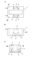
図1は、本発明を適用した樹脂成形品1の概略構成を示すものである。図1(a)は平面図、図1(b)は側面図、図1(c)は正面図である。
FIG. 1 shows a schematic configuration of a resin molded
この樹脂成形品1は、例えば熱硬化性の樹脂等からなる樹脂部中に2つの部品(例えば希土類金属磁石)をインサート成形したものである。前記樹脂成形品1においては、樹脂部が大きく2つに分割され、これら各樹脂部2A,2Bが筐体状に連結された構造を有しており、分割された樹脂部2A,2Bにそれぞれ部品3がインサート成形されている。部品3は、金型に設けられたガイドによって位置決めされており、したがって、樹脂部2A,2Bには、ガイドに対応してガイド孔4が形成されている。
This resin molded
また、本発明の樹脂成形品1においては、前記各部品3に対応してガス抜き孔5が形成されており、これが大きな特徴である。ガス抜き孔5は、成形時に反応ガスのガス抜きを促進するものであり、部品3の表面の一部が露呈するように形成されている。このガス抜き孔5は、ガス抜きを促進するに足る開口径を有していればよく、なるべく小さな径で形成することが好ましい。
Moreover, in the resin molded
前記ガス抜き孔5は、部品3の表面の一部と重なる形で形成すればよいが、その開口形状が部品3の一表面内に収まるように形成することが好ましい。ガス抜き孔5が部品3の表面からはみ出す形で形成されると、ガス抜き孔5を形成するコアピンに樹脂圧が加わり、バリやガス抜き孔5の閉塞等に繋がるおそれがある。また、前記ガス抜き孔5は、各部品3に対応して形成することが好ましく、したがって、インサートされる部品3が複数ある場合には、ガス抜き孔5も複数設けることが好ましい。
The
樹脂成形品1には、前記ガス抜き孔5の他、前記ガイド孔4も設けられているが、これら開口部は、部品3の一面側にのみ配置されていることが好ましい。例えば、固定ピン等による開口部が前記ガイド孔4やガス抜き孔5の反対側に形成されていると、強度の低下やクラックの発生が問題になる可能性がある。
The resin molded
ここで、例えば金型として上型と下型を用いてインサート成形を行う場合、成形後金型を開く際には、通常、樹脂成形品1は下型に位置している。したがって、樹脂成形品1の上部に滞留したガスは、金型を開くことにより、比較的容易に開放される。これに対して樹脂成形品1の下部に滞留したガスは、下型と樹脂成形品1の間、あるいは樹脂成形品1とインサートされる部品3の間に封じ込められているため容易に開放されない。そのため金型を開く際には、樹脂成形品1の上下部に急激な圧力変化を生じ、フクレやクラックの発生を、より顕著なものとしてしまう。したがって、このような不都合を解消するためには、コアピン(ガス抜き孔5)は樹脂成形品1が位置する側の金型、前述の例でいえば下型の成形時に部品を位置決めするガイドピンにより形成される開口部(ガイド孔4)のある面側にあることが望ましい。
Here, for example, when insert molding is performed using an upper mold and a lower mold as molds, the resin molded
以上の構成を有する樹脂成形品1においては、ガス抜き孔5が設けられているので、ガス抜き不良によるフクレや変形、クラック等が発生することはない。通常、部品3の周囲の樹脂厚の薄い部分、例えば図1に示す例では矢印で示す部分において、フクレや変形が発生し易いが、ガス抜きが円滑に行われることにより、このような障害を解消することができる。
In the resin molded
次に、前記樹脂成形品1の成形方法について説明する。前記樹脂成形品1の成形に際しては、部品をインサート成形する必要があるが、このように部品をインサート成形する場合には、部品と樹脂の熱膨張係数の違いを考慮する必要がある。組み込む部品と樹脂は、通常、熱膨張係数が異なるため、一体成形後、クラックが入り易い。特に、異方性を持つ希土類金属磁石の場合、前記傾向が顕著である。配向方向と直交する方向における熱膨張係数が負であるためである。希土類金属磁石をインサート成形した場合、前記熱膨張係数の関係から、一体成形後の冷却時において希土類金属磁石の周囲を取り囲んだ樹脂は収縮するのに対し、樹脂に取り囲まれた希土類金属磁石は膨張する。その結果、大きな応力が発生することになる。したがって希土類金属磁石は、樹脂等の他の物質と一体化した場合、温度変化時に発生する応力に敏感なためクラックを生じやすい。よって、それを考慮して工程を設計する必要がある。また、樹脂成形に際しては、ガスが発生することがあるが、この場合、発生したガスが、樹脂のまわり込み等により外部に排出できず、樹脂と磁石界面に溜まることがある。このような場合、冷却時に、樹脂が縮むのに対し磁石が膨張し、界面のガスが押し潰されて高い内圧を発生することになる。したがって、前記ガスを速やかにガス抜きし得るように工程を設計することも必要である。本実施形態の成形方法は、これらの事項を考慮して工程を最適化したものである。
Next, a method for molding the resin molded
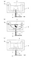
すなわち、本実施形態において前記樹脂成形品1を成形するには、例えば図2に示すように、直方体形状を有する金型6のキャビティ内に部品3を配置し、いわゆるインサート成形を行う。図2(a)は、樹脂注入前の部品セッティング状態を示すものであり、金型6の底面6aに複数のガイド7が設けられており、これらガイド7によって部品3が前記底面6aの面内方向で位置決めがなされる。
That is, in order to mold the resin molded
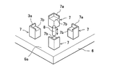
ガイド7は、本例の場合、部品3の4隅に対応して4箇所に設けられており、各ガイド7は、例えば図3に示すように、部品3の周面を支持する立ち上がり壁7aと、部品3の底面を支持する載置面7bとから構成されている。したがって、インサートされる部品3は、前記ガイド7の載置面7bによって高さ方向の位置決めがされ、前記立ち上がり壁7aによって面内方向の移動が規制される。
In this example, the
また、本発明においては、ガス抜きのためのコアピン8が金型6に設置されており、成形時にガス抜きを円滑に行うようになっている。このコアピン8は、所定の径を有する断面円形のピンであり、油圧装置9によって金型6に対して挿脱自在とされている。コアピン8は、樹脂成形品1の大きさや発生ガス量、他の部分からのガス抜けの程度等を考慮して、その数や径を設定すればよく、例えば必要に応じて各部品3に対応して複数設けてもよい。なお、前記コアピン8を加圧する装置としては、前記油圧装置9に限らず、例えばバネ等により加圧するものであってもよい。樹脂注入前においては、前記コアピン8の先端が前記ガイド7の載置面7bと同じ高さになるように、油圧装置9によって押し込まれている。
Further, in the present invention, the
この状態で樹脂の注入を行うが、このとき、部品3は前記ガイド7の載置面7b上に載置されているだけであるので、上方向には移動可能である。したがって、部品3の浮き上がりによる樹脂のまわり込みが懸念される。この樹脂のまわり込みのため、発生したガスが抜けにくくなる恐れがある。そこで、本実施形態では、樹脂の流れを利用して、前記部品3の浮き上がりを防止すればさらに効果的である。
In this state, the resin is injected. At this time, since the
具体的には、前記金型6において、部品3よりも高い位置にゲート10を設け、ここから樹脂を注入する。このように、部品3よりも高い位置に設けられたゲート10から樹脂を注入すると、樹脂の流れは、いわゆるダウンフローとなり、図2(b)中に矢印で示すように、上から下に向かう流れとなる。また、樹脂の流れの一部は、部品3上を通過する形になる。
Specifically, in the
このような樹脂の流れにより、部品3に対して矢印Fで示す方向の力が加わり、その結果、部品3は金型6のガイド7が形成された金型面6a、すなわちガイド7の載置面7bに向かって押し付けられることになる。したがって、部品3は、樹脂注入時に浮き上がることがなく、ガイド7による位置決め状態が維持され、部品3の位置ずれの無い成形が可能になる。
Due to such a resin flow, a force in the direction indicated by the arrow F is applied to the
この場合、部品3に対する樹脂注入口(ゲート10)の高さが重要である。具体的には、先ず、ガイド7の載置面7bによって高さが決まる部品3の底面を基準とする。この底面を基準h0とすると、部品3の上面の位置が高さhということになる。この場合、前記底面を基準h0として、前記部品3の重心の高さよりも高い位置にゲート10を設ける必要がある。部品3が上下対称な形状を有する場合には、前記高さhの1/2よりも高い位置にゲート10を設ける必要がある。これよりも低い位置にゲート10を設けると、樹脂の流れが部品3に対して上昇する方向となり、部品3の浮き上がりの可能性が高くなる。好ましくは、部品3の高さh以上の位置にゲート10を設けるのが良い。
In this case, the height of the resin injection port (gate 10) with respect to the
樹脂の充填の後、図2(c)に示すように、油圧装置9の操作によりコアピン8を後退させる。このコアピン8を後退させるタイミングは、樹脂の硬化が始まった後、硬化が完全に終わる前であるが、タイミングがあまり早すぎると、未硬化の樹脂がコアピン8を後退した空間内に流れ込む可能性がある。また、樹脂が完全に硬化してからコアピン8を引き抜いたのでは、十分な効果が得られなくなるおそれがある。したがって、樹脂の冷却開始時から金型6が開くまでの間の何れかの時にコアピン8を後退させることが好ましく、前記期間の概ね中間時点から金型が開くまでの間が好ましく、さらに金型が開く直前にコアピン8を後退させることが好ましい。
After filling the resin, the
コアピン8の後退は、例えばコアピン8を所定量後退させることによって行ってもよいし、コアピン8を金型6から完全に外部に引き抜く形で行ってもよい。前者の場合、コアピン8の後退により空間kが形成され、この空間k内が周囲に比べて減圧状態になることから、ガス抜きが促進される。後者の場合には、コアピン8を引き抜いた孔から外部に速やかに反応ガスが逃散される。
The
以上の構成を有する本発明においては、樹脂成形品を構成する樹脂材料として、任意の樹脂材料を用いることができるが、特に熱硬化性の樹脂を用いた場合に適用することで、その効果を引き出すことができる。これは、樹脂成形品に熱硬化性の樹脂を用いた場合には、ガスが発生し易く、前記ガス抜きによる効果が顕著であるからである。 In the present invention having the above-described configuration, any resin material can be used as the resin material constituting the resin molded product, but the effect can be obtained by applying it particularly when a thermosetting resin is used. It can be pulled out. This is because when a thermosetting resin is used for the resin molded product, gas is easily generated, and the effect of degassing is remarkable.
以上が本発明の成形方法の基本的な考えであるが、成形に際しては、これに加えて、例えば部品3の長手方向に沿って樹脂の流れが形成されるように、部品3の略長手方向から樹脂を注入することが好ましい。前記成形方法により、前述の通り発生ガスによるフクレやクラックを防止できるが、これに加えて樹脂の流れを考慮することにより、一体成形品の構造に起因するクラックを防止できるからである。
The above is the basic idea of the molding method of the present invention. In molding, in addition to this, for example, a substantially longitudinal direction of the
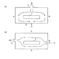
例えば、部品3をインサート成形した場合、成形される樹脂成形品においては、部品3の長手方向に沿って形成される部分の樹脂厚が薄いことが多い。図4は、金型6内に部品2を配置した場合の樹脂成形品の代表的な形状例を示すものである。この樹脂成形品においては、部品2の4辺に対応した樹脂部A,B,C,Dを有しており、それぞれの樹脂部A,B,C,Dの厚さがt1,t2,t3,t4とする。そして、t1,t2,t3>t4であり、樹脂の厚さが最も薄い部分が樹脂部Dとする。したがって、成形される樹脂成形品において、最も強度が弱いのは樹脂部Dということになる。
For example, when the
このような形状の樹脂成形品を成形する場合、例えば図5(a)に示すように、樹脂部C側から樹脂を注入すると、樹脂の流れは図中矢印で示すようなものとなる。すなわち、樹脂部C側から金型6のキャビティ内に注入された樹脂の流れは、部品3によって遮られ、部品3を避けながら移動する。そして、樹脂部Dに関しては、樹脂部Aや樹脂部Bを回り込んだ後、樹脂の流れが到達する。このとき、樹脂部Dにおいて、部品3によって分流された樹脂の流れが合流することになり、その結果、図中wで示す位置において、いわゆるウエルドを起こす。ウエルドは、強度低下の大きな原因となり、これが最も強度の弱い樹脂部Dにおいて起こると、この部分でのクラックの発生に繋がり、信頼性を著しく損なうことになる。
When a resin molded product having such a shape is molded, for example, as shown in FIG. 5A, when resin is injected from the resin portion C side, the flow of the resin is as indicated by arrows in the figure. That is, the flow of resin injected into the cavity of the
一方、図5(b)に示すように、樹脂部A側から樹脂を注入すると、やはり部品3によって樹脂の流れが部品3に沿って分割され、部品3の終端、この場合には樹脂部Bで合流する。したがって、樹脂部Bにおいてウエルドが起こるが、樹脂部Bは樹脂の厚さが厚く、ウエルドが起こったとしても、強度低下の影響は僅かであり、これが原因でクラックが入ることはない。また、樹脂の厚さが最も薄い樹脂部Dについて言えば、この部分には部品3を避けながら移動する樹脂の流れが形成され、樹脂流れの合わさり目となることがないので、ウエルドが起こることはない。したがって、強度的に最も問題となる樹脂部Dにおいて強度が低下することがなく、クラックの発生が抑えられる。
On the other hand, as shown in FIG. 5B, when the resin is injected from the resin portion A side, the flow of the resin is also divided along the
前述のように、樹脂の注入方向によって部品3の周囲での樹脂の流れが変わる。したがって、樹脂成形品の成形に際しては、図5(b)に示すように、樹脂の厚さが最も薄く強度的に問題となる樹脂部Dに沿って平行に樹脂の流れが形成されるように、すなわち樹脂部A側(あるいは樹脂部B側)から樹脂を注入することが好ましいということになる。
As described above, the resin flow around the
また、樹脂成形品の強度を向上するために、樹脂に繊維状フィラーを添加した場合や、部品2に負の熱膨張係数を有する希土類金属磁石等を用いた場合には、これに応じて樹脂の注入方向を考慮することが好ましい。 In addition, when a fibrous filler is added to the resin in order to improve the strength of the resin molded product, or when a rare earth metal magnet having a negative coefficient of thermal expansion is used for the component 2, the resin is changed accordingly. It is preferable to consider the injection direction.
以上のように、本発明によれば、コアピン8の引き抜きにより反応ガスのガス抜きを確実に行うことができ、ガス抜き不良によるフクレや変形等の無い品質の高い樹脂成形品を作製することが可能である。また、前記に加えて、部品の位置ずれを抑制するために樹脂の注入を適正に制御することで、ガス抜きの効果をさらに大なるものとすることができ、不良品の発生を抑え、樹脂成形品の歩留まりを大幅に向上することが可能である。また、前記に加えて、樹脂の注入を適正に制御することで、クラック等の発生を確実に抑制することができ、前記ガス抜きの効果による不良品の発生の抑制と相俟って、樹脂成形品の歩留まりを大幅に向上することが可能である。
As described above, according to the present invention, the reaction gas can be surely vented by pulling out the
以下においては、実際に樹脂成形品を成形し、本発明の効果を確かめた。 In the following, a resin molded product was actually molded to confirm the effect of the present invention.
実施例
本実施例において作製した樹脂成形品の形状は図1に示す通りであり、樹脂部中に2つの希土類金属磁石をインサート成形した。樹脂中にインサート成形した希土類金属磁石は、10mm×10mm×3mmであり、通常の粉末冶金の手法により作製した。希土類金属磁石における配向方向は厚さ方向(3mmの方向)であり、表面にはNiめっきを施した。注入する樹脂としては、ガラスフィラーを40質量%充填した熱硬化性樹脂を用いた。
EXAMPLE The shape of the resin molded product produced in this example is as shown in FIG. 1, and two rare earth metal magnets were insert-molded in the resin part. The rare earth metal magnet insert-molded in the resin is 10 mm × 10 mm × 3 mm, and was produced by a usual powder metallurgy technique. The orientation direction in the rare earth metal magnet was the thickness direction (3 mm direction), and the surface was plated with Ni. As the resin to be injected, a thermosetting resin filled with 40% by mass of a glass filler was used.
前記樹脂成形品を、図2に示す方法にしたがって成形した。作製した樹脂成形品の数は200個である。なお、本実施例においては、樹脂の注入後、金型を開く直前にコアピンを後退させることによりガス抜きを行った。したがって、図1に示すように、成形された樹脂成形品には、ガス抜き孔が形成されていた。 The resin molded product was molded according to the method shown in FIG. The number of produced resin molded products is 200. In this example, after the resin was injected, the core pin was retracted immediately before the mold was opened, thereby degassing. Therefore, as shown in FIG. 1, a vent hole is formed in the molded resin molded product.
各樹脂成形品について、樹脂が固化した後、金型から取り出し、180℃にて3時間エージングを行った。その後、樹脂部におけるフクレや変形、クラック等の発生状況を目視にて確認した。フクレや変形、クラック等が発生した樹脂成形品の数量を成形個数(200個)で除し、不良品発生率を求めて評価した。その結果、不良品発生率は0%と極めて良好な値を示していた。 About each resin molded product, after resin solidified, it took out from the metal mold | die and performed aging at 180 degreeC for 3 hours. Thereafter, the occurrence of swelling, deformation, cracks, and the like in the resin portion was visually confirmed. The number of resin molded products in which blisters, deformation, cracks, etc. occurred was divided by the number of molded products (200), and the defective product occurrence rate was determined and evaluated. As a result, the defective product generation rate was an extremely good value of 0%.
比較例
実施例と同様の樹脂成形品を成形したが、コアピンの引き抜きによるガス抜きを行わなかった。したがって、作製した樹脂成形品には、ガス抜き孔は形成されていない。この場合には、フクレや変形、クラック等による不良品発生率が96%と実施例に比べて著しく大きな値であった。
Although the resin molded product similar to the comparative example was molded, the gas was not removed by drawing the core pin. Therefore, the vent hole is not formed in the produced resin molded product. In this case, the defective product generation rate due to blistering, deformation, cracks, etc. was 96%, which was a significantly large value compared to the example.
1 樹脂成形品、2A,2B 樹脂部、3 部品、4 ガイド孔、5 ガス抜き孔、6 金型、7 ガイド、7a 立ち上がり壁、7b 載置面、8 コアピン、9 油圧装置、10 ゲート 1 resin molded product, 2A, 2B resin part, 3 parts, 4 guide hole, 5 vent hole, 6 mold, 7 guide, 7a rising wall, 7b mounting surface, 8 core pin, 9 hydraulic device, 10 gate
Claims (5)
前記金型に前記部品表面に当接するコアピンを設け、金型内に樹脂を充填し、樹脂の硬化が始まった後、硬化が完全に終わる前に前記コアピンを引き抜くことでガス抜きを行うことを特徴とする樹脂成形品の成形方法。 When insert-molding parts placed in the mold cavity with thermosetting resin,
The mold is provided with a core pin that comes into contact with the surface of the component, the resin is filled in the mold, and after the resin has been cured, the core pin is withdrawn before the curing is completely completed. A method for molding a resin molded product.
Priority Applications (1)
| Application Number | Priority Date | Filing Date | Title |
|---|---|---|---|
| JP2005047005A JP5114827B2 (en) | 2005-02-23 | 2005-02-23 | Molding method of resin molded products |
Applications Claiming Priority (1)
| Application Number | Priority Date | Filing Date | Title |
|---|---|---|---|
| JP2005047005A JP5114827B2 (en) | 2005-02-23 | 2005-02-23 | Molding method of resin molded products |
Publications (2)
| Publication Number | Publication Date |
|---|---|
| JP2006231606A JP2006231606A (en) | 2006-09-07 |
| JP5114827B2 true JP5114827B2 (en) | 2013-01-09 |
Family
ID=37039795
Family Applications (1)
| Application Number | Title | Priority Date | Filing Date |
|---|---|---|---|
| JP2005047005A Active JP5114827B2 (en) | 2005-02-23 | 2005-02-23 | Molding method of resin molded products |
Country Status (1)
| Country | Link |
|---|---|
| JP (1) | JP5114827B2 (en) |
Families Citing this family (1)
| Publication number | Priority date | Publication date | Assignee | Title |
|---|---|---|---|---|
| JP5747422B2 (en) | 2010-02-01 | 2015-07-15 | ディビーエムレフレックス エンタプライズ インコーポレイテッド | Thick lens molded with the same resin layer using a two-stage injection molding process |
Family Cites Families (5)
| Publication number | Priority date | Publication date | Assignee | Title |
|---|---|---|---|---|
| JPH0729388B2 (en) * | 1986-08-13 | 1995-04-05 | ブリヂストンスポーツ株式会社 | Golf ball manufacturing method |
| JPH01222913A (en) * | 1988-03-02 | 1989-09-06 | Seiko Epson Corp | Method for manufacturing closed vessel |
| JP2756615B2 (en) * | 1991-05-24 | 1998-05-25 | 松下電器産業株式会社 | Insert molded article and method of manufacturing the same |
| JPH091566A (en) * | 1995-06-19 | 1997-01-07 | Araco Corp | Pad positioning method for sticky sheet |
| JP2003131592A (en) * | 2001-10-22 | 2003-05-09 | Seiko Precision Inc | El-inserted molded member with integrated el driving circuit |
-
2005
- 2005-02-23 JP JP2005047005A patent/JP5114827B2/en active Active
Also Published As
| Publication number | Publication date |
|---|---|
| JP2006231606A (en) | 2006-09-07 |
Similar Documents
| Publication | Publication Date | Title |
|---|---|---|
| JP5329202B2 (en) | Molded coil manufacturing method | |
| US8057723B2 (en) | Method of manufacturing insert-molded article and apparatus therefor | |
| JP5580116B2 (en) | Manufacturing method of resin molded product by injection molding | |
| JP5174874B2 (en) | Compression molding die and compression molding method | |
| JP5422191B2 (en) | Molded coil manufacturing method | |
| KR20040047596A (en) | Method of Resin Encapsulation, Apparatus for Resin Encapsulation, Method of Manufacturing Semiconductor Device, Semiconductor Device and Resin Material | |
| JP4611249B2 (en) | Resin sealing method for rotor laminated core | |
| EP2660858A1 (en) | Semiconductor module, mould device, and mould-forming method | |
| JP5114827B2 (en) | Molding method of resin molded products | |
| JP4426880B2 (en) | Resin sealing device and resin sealing method | |
| JP2006272657A (en) | Molding method and molding machine | |
| JP2006231604A (en) | Molding method | |
| JP2011218623A (en) | Insert molding apparatus, and insert molding method | |
| JP6288120B2 (en) | Method for manufacturing resin-molded mold and resin molded part of electronic component | |
| KR101143939B1 (en) | Lower die block and die unit for modling an electronic device including the same | |
| JP3280634B2 (en) | Semiconductor package manufacturing method, mold for manufacturing semiconductor package, and semiconductor package | |
| JP6455647B1 (en) | Rubber mold insert | |
| JP2001338940A (en) | Resin molding apparatus of semiconductor ic and resin molding method | |
| CN108604577B (en) | Electronic device and method for manufacturing electronic device | |
| JP5401703B2 (en) | Mold | |
| JP4151682B2 (en) | Manufacturing method of semiconductor device | |
| JP4419686B2 (en) | Molding method for composite parts | |
| JP4107306B2 (en) | Semiconductor device manufacturing equipment | |
| JP2017034238A (en) | Electronic component encapsulation device and electronic component encapsulation method employing the same | |
| JP2006231784A (en) | Resin molded product |
Legal Events
| Date | Code | Title | Description |
|---|---|---|---|
| A621 | Written request for application examination |
Free format text: JAPANESE INTERMEDIATE CODE: A621 Effective date: 20080131 |
|
| A977 | Report on retrieval |
Free format text: JAPANESE INTERMEDIATE CODE: A971007 Effective date: 20100428 |
|
| A131 | Notification of reasons for refusal |
Free format text: JAPANESE INTERMEDIATE CODE: A131 Effective date: 20100506 |
|
| A521 | Written amendment |
Free format text: JAPANESE INTERMEDIATE CODE: A523 Effective date: 20100705 |
|
| A131 | Notification of reasons for refusal |
Free format text: JAPANESE INTERMEDIATE CODE: A131 Effective date: 20110705 |
|
| A521 | Written amendment |
Free format text: JAPANESE INTERMEDIATE CODE: A523 Effective date: 20110901 |
|
| A131 | Notification of reasons for refusal |
Free format text: JAPANESE INTERMEDIATE CODE: A131 Effective date: 20120703 |
|
| A521 | Written amendment |
Free format text: JAPANESE INTERMEDIATE CODE: A523 Effective date: 20120831 |
|
| TRDD | Decision of grant or rejection written | ||
| A01 | Written decision to grant a patent or to grant a registration (utility model) |
Free format text: JAPANESE INTERMEDIATE CODE: A01 Effective date: 20120918 |
|
| A01 | Written decision to grant a patent or to grant a registration (utility model) |
Free format text: JAPANESE INTERMEDIATE CODE: A01 |
|
| A61 | First payment of annual fees (during grant procedure) |
Free format text: JAPANESE INTERMEDIATE CODE: A61 Effective date: 20121001 |
|
| R150 | Certificate of patent or registration of utility model |
Free format text: JAPANESE INTERMEDIATE CODE: R150 Ref document number: 5114827 Country of ref document: JP Free format text: JAPANESE INTERMEDIATE CODE: R150 |
|
| FPAY | Renewal fee payment (event date is renewal date of database) |
Free format text: PAYMENT UNTIL: 20151026 Year of fee payment: 3 |