JP5114585B2 - Method and apparatus for efficiently obtaining synchronization in spread spectrum communications - Google Patents
Method and apparatus for efficiently obtaining synchronization in spread spectrum communications Download PDFInfo
- Publication number
- JP5114585B2 JP5114585B2 JP2011130586A JP2011130586A JP5114585B2 JP 5114585 B2 JP5114585 B2 JP 5114585B2 JP 2011130586 A JP2011130586 A JP 2011130586A JP 2011130586 A JP2011130586 A JP 2011130586A JP 5114585 B2 JP5114585 B2 JP 5114585B2
- Authority
- JP
- Japan
- Prior art keywords
- sequence
- correlator
- length
- correlation
- golay
- Prior art date
- Legal status (The legal status is an assumption and is not a legal conclusion. Google has not performed a legal analysis and makes no representation as to the accuracy of the status listed.)
- Expired - Fee Related
Links
- 238000000034 method Methods 0.000 title claims description 25
- 238000001228 spectrum Methods 0.000 title claims description 22
- 238000004891 communication Methods 0.000 title description 20
- 230000000295 complement effect Effects 0.000 claims description 92
- 108091006146 Channels Proteins 0.000 description 56
- 238000012545 processing Methods 0.000 description 40
- 230000000875 corresponding effect Effects 0.000 description 26
- 230000006870 function Effects 0.000 description 20
- 230000007480 spreading Effects 0.000 description 20
- 239000013598 vector Substances 0.000 description 19
- 230000005540 biological transmission Effects 0.000 description 12
- 238000010586 diagram Methods 0.000 description 12
- PCHJSUWPFVWCPO-UHFFFAOYSA-N gold Chemical group [Au] PCHJSUWPFVWCPO-UHFFFAOYSA-N 0.000 description 8
- 230000002596 correlated effect Effects 0.000 description 7
- 230000008901 benefit Effects 0.000 description 6
- 230000001413 cellular effect Effects 0.000 description 6
- 230000001934 delay Effects 0.000 description 5
- 230000001427 coherent effect Effects 0.000 description 4
- 238000001514 detection method Methods 0.000 description 4
- 238000005562 fading Methods 0.000 description 4
- 101100368149 Mus musculus Sync gene Proteins 0.000 description 3
- 238000005311 autocorrelation function Methods 0.000 description 3
- 230000010267 cellular communication Effects 0.000 description 3
- 239000002131 composite material Substances 0.000 description 3
- 201000011591 microinvasive gastric cancer Diseases 0.000 description 3
- 230000011664 signaling Effects 0.000 description 3
- 230000001360 synchronised effect Effects 0.000 description 3
- 238000007792 addition Methods 0.000 description 2
- 238000010276 construction Methods 0.000 description 2
- 230000010354 integration Effects 0.000 description 2
- 238000010295 mobile communication Methods 0.000 description 2
- 230000008569 process Effects 0.000 description 2
- QVWYCTGTGHDWFQ-AWEZNQCLSA-N (2s)-2-[[4-[2-chloroethyl(2-methylsulfonyloxyethyl)amino]benzoyl]amino]pentanedioic acid Chemical compound CS(=O)(=O)OCCN(CCCl)C1=CC=C(C(=O)N[C@@H](CCC(O)=O)C(O)=O)C=C1 QVWYCTGTGHDWFQ-AWEZNQCLSA-N 0.000 description 1
- 102100032055 Elongation of very long chain fatty acids protein 1 Human genes 0.000 description 1
- 102100032050 Elongation of very long chain fatty acids protein 2 Human genes 0.000 description 1
- 101000771413 Homo sapiens Aquaporin-9 Proteins 0.000 description 1
- 101000921370 Homo sapiens Elongation of very long chain fatty acids protein 1 Proteins 0.000 description 1
- 101000921368 Homo sapiens Elongation of very long chain fatty acids protein 2 Proteins 0.000 description 1
- 101100125012 Saccharomyces cerevisiae (strain ATCC 204508 / S288c) ECM10 gene Proteins 0.000 description 1
- 230000006978 adaptation Effects 0.000 description 1
- 230000002238 attenuated effect Effects 0.000 description 1
- 238000005314 correlation function Methods 0.000 description 1
- 125000004122 cyclic group Chemical group 0.000 description 1
- 238000013461 design Methods 0.000 description 1
- 238000011161 development Methods 0.000 description 1
- 238000001914 filtration Methods 0.000 description 1
- QUCZBHXJAUTYHE-UHFFFAOYSA-N gold Chemical group [Au].[Au] QUCZBHXJAUTYHE-UHFFFAOYSA-N 0.000 description 1
- 238000012986 modification Methods 0.000 description 1
- 230000004048 modification Effects 0.000 description 1
- 230000000737 periodic effect Effects 0.000 description 1
- 230000010363 phase shift Effects 0.000 description 1
- 238000013139 quantization Methods 0.000 description 1
- 230000005855 radiation Effects 0.000 description 1
- 230000009467 reduction Effects 0.000 description 1
- 230000002441 reversible effect Effects 0.000 description 1
- 238000006467 substitution reaction Methods 0.000 description 1
Images


Classifications
-
- H—ELECTRICITY
- H04—ELECTRIC COMMUNICATION TECHNIQUE
- H04B—TRANSMISSION
- H04B1/00—Details of transmission systems, not covered by a single one of groups H04B3/00 - H04B13/00; Details of transmission systems not characterised by the medium used for transmission
- H04B1/69—Spread spectrum techniques
- H04B1/707—Spread spectrum techniques using direct sequence modulation
- H04B1/7073—Synchronisation aspects
- H04B1/7085—Synchronisation aspects using a code tracking loop, e.g. a delay-locked loop
-
- H—ELECTRICITY
- H04—ELECTRIC COMMUNICATION TECHNIQUE
- H04J—MULTIPLEX COMMUNICATION
- H04J13/00—Code division multiplex systems
- H04J13/0007—Code type
- H04J13/0011—Complementary
- H04J13/0014—Golay
-
- H—ELECTRICITY
- H04—ELECTRIC COMMUNICATION TECHNIQUE
- H04B—TRANSMISSION
- H04B1/00—Details of transmission systems, not covered by a single one of groups H04B3/00 - H04B13/00; Details of transmission systems not characterised by the medium used for transmission
- H04B1/69—Spread spectrum techniques
- H04B1/707—Spread spectrum techniques using direct sequence modulation
- H04B1/7073—Synchronisation aspects
- H04B1/7075—Synchronisation aspects with code phase acquisition
- H04B1/708—Parallel implementation
-
- H—ELECTRICITY
- H04—ELECTRIC COMMUNICATION TECHNIQUE
- H04B—TRANSMISSION
- H04B1/00—Details of transmission systems, not covered by a single one of groups H04B3/00 - H04B13/00; Details of transmission systems not characterised by the medium used for transmission
- H04B1/69—Spread spectrum techniques
- H04B1/707—Spread spectrum techniques using direct sequence modulation
- H04B1/709—Correlator structure
- H04B1/7093—Matched filter type
-
- H—ELECTRICITY
- H04—ELECTRIC COMMUNICATION TECHNIQUE
- H04B—TRANSMISSION
- H04B7/00—Radio transmission systems, i.e. using radiation field
- H04B7/24—Radio transmission systems, i.e. using radiation field for communication between two or more posts
- H04B7/26—Radio transmission systems, i.e. using radiation field for communication between two or more posts at least one of which is mobile
- H04B7/2662—Arrangements for Wireless System Synchronisation
- H04B7/2668—Arrangements for Wireless Code-Division Multiple Access [CDMA] System Synchronisation
-
- H—ELECTRICITY
- H04—ELECTRIC COMMUNICATION TECHNIQUE
- H04L—TRANSMISSION OF DIGITAL INFORMATION, e.g. TELEGRAPHIC COMMUNICATION
- H04L7/00—Arrangements for synchronising receiver with transmitter
- H04L7/04—Speed or phase control by synchronisation signals
- H04L7/041—Speed or phase control by synchronisation signals using special codes as synchronising signal
-
- H—ELECTRICITY
- H04—ELECTRIC COMMUNICATION TECHNIQUE
- H04W—WIRELESS COMMUNICATION NETWORKS
- H04W56/00—Synchronisation arrangements
-
- H—ELECTRICITY
- H04—ELECTRIC COMMUNICATION TECHNIQUE
- H04W—WIRELESS COMMUNICATION NETWORKS
- H04W74/00—Wireless channel access
- H04W74/08—Non-scheduled access, e.g. ALOHA
Landscapes
- Engineering & Computer Science (AREA)
- Computer Networks & Wireless Communication (AREA)
- Signal Processing (AREA)
- Mobile Radio Communication Systems (AREA)
- Synchronisation In Digital Transmission Systems (AREA)
Description
本発明は、遠隔通信に関し、具体的には、直接拡散型のスペクトラム拡散無線通信システムでのトランシーバの同期化に関する。 The present invention relates to telecommunications, and in particular to transceiver synchronization in a direct spread spectrum spread spectrum communication system.
セルラ無線システムおよび衛星無線システムなどの現代の通信システムでは、さまざまな動作のモード(アナログ、ディジタル、およびハイブリッド)と、周波数分割多元接続(FDMA)、時分割多元接続(TDMA)、符号分割多元接続(CDMA)、およびこれらの技法のハイブリッドなどのアクセス技法が使用される。 In modern communication systems, such as cellular and satellite radio systems, various modes of operation (analog, digital, and hybrid) and frequency division multiple access (FDMA), time division multiple access (TDMA), code division multiple access Access techniques such as (CDMA) and hybrids of these techniques are used.
ディジタル・セルラ通信システムは、システム容量を最適化し、階層セル構造すなわちマクロセル、マイクロセル、ピコセルなどの構造をサポートする機能性を拡張してきた。用語「マクロセル」は、一般に、通常のセルラ電話システムのセルのサイズ(たとえば少なくとも約1kmの半径)に匹敵するサイズを有するセルを指し、用語「マイクロセル」および「ピコセル」は、一般に、より小さいセルを指す。たとえば、マイクロセルは、公共の室内または戸外の区域、たとえば会議センタまたは繁華街をカバーすることができ、ピコセルは、オフィスの廊下または高層建築の1階をカバーすることができる。無線カバレッジの観点から、マクロセル、マイクロセル、およびピコセルは、互いに別個とするか、異なるトラフィック・パターンまたは無線環境を扱うために互いにオーバーラップさせることができる。 Digital cellular communication systems have optimized system capacity and expanded functionality to support hierarchical cell structures such as macrocells, microcells, picocells, and the like. The term “macrocell” generally refers to a cell having a size comparable to that of a cell in a normal cellular telephone system (eg, a radius of at least about 1 km), and the terms “microcell” and “picocell” are generally smaller. Refers to a cell. For example, a microcell can cover a public indoor or outdoor area, such as a conference center or downtown, and a picocell can cover an office corridor or the first floor of a high-rise building. From a radio coverage perspective, macrocells, microcells, and picocells can be separate from each other or overlap each other to handle different traffic patterns or radio environments.
通常のセルラ移動無線電話システムには、1つまたは複数の基地局(BS)と複数の移動局(MS)が含まれる。基地局には、通常は、モバイル・スイッチング・センタ(MSC)などのコア・ネットワーク・タイプ・ノードに接続された制御処理ユニットが含まれ、MSCは、公衆交換電話網(PSTN)に接続される。そのようなセルラ無線電話システムの一般的な態様は、当技術分野で既知である。基地局は、制御処理ユニットによって制御されるトラフィック・チャネル・トランシーバを介して複数の音声チャネルまたはデータ・チャネルを処理する。また、各基地局には、やはり制御処理ユニットによって制御される複数の制御チャネルを処理することができるものとすることができる制御チャネル・トランシーバが含まれる。制御チャネル・トランシーバは、基地局の制御チャネルを介して、その制御チャネルに同調(またはロック)された移動体へ制御情報をブロードキャストする。 A typical cellular mobile radiotelephone system includes one or more base stations (BS) and a plurality of mobile stations (MS). A base station typically includes a control processing unit connected to a core network type node such as a mobile switching center (MSC), which is connected to a public switched telephone network (PSTN). . The general aspects of such cellular radiotelephone systems are known in the art. The base station processes multiple voice channels or data channels via a traffic channel transceiver controlled by a control processing unit. Each base station also includes a control channel transceiver that may be capable of processing multiple control channels that are also controlled by the control processing unit. The control channel transceiver broadcasts control information via the base station control channel to mobiles tuned (or locked) to that control channel.
移動体は、制御チャネルでブロードキャストされる情報を、その音声および制御チャネル・トランシーバで受信する。移動体処理ユニットは、その移動体がロックする候補であるセルの特性を含む受信した制御チャネル情報を評価し、その移動体がロックしなければならないセルを判定する。有利なことに、受信した制御チャネル情報には、それに関連するセルに関する絶対情報だけではなく、その制御チャネルに関連するセルに隣接する他のセルに関する相対情報も含まれる。 The mobile receives information broadcast on the control channel at its voice and control channel transceiver. The mobile processing unit evaluates the received control channel information including the characteristics of the cells that are candidates for locking by the mobile and determines the cells that the mobile should lock. Advantageously, the received control channel information includes not only absolute information about the cell associated with it, but also relative information about other cells adjacent to the cell associated with the control channel.
北米では、TDMAを使用するディジタル・セルラ無線電話システムを、digital advanced mobile phone service(D−AMPS)と称し、その特性の一部が、Telecommunications Industry Associationおよび電子工業会(TIA/EIA)によって公表されたTIA/EIA/IS−136標準規格で仕様を定められている。直接拡散CDMA(DS−CDMA)を使用するもう1つのディジタル通信システムが、TIA/EIA/IS−95標準規格で仕様を定められており、周波数ホッピングCDMA通信システムが、EIA SP 3389標準規格(PCS 1900)で仕様を定められている。PCS 1900標準規格は、GSMシステムの実装であり、GSMシステムは、北米以外で一般的であり、パーソナル通信サービス(PCS)システムのために導入されている。 In North America, digital cellular radiotelephone systems using TDMA are referred to as digital advanced mobile phone services (D-AMPS), some of which are published by Telecommunications Industry Association and Electronic Industries Association (TIA / EIA). The specification is defined in the TIA / EIA / IS-136 standard. Another digital communication system that uses direct spreading CDMA (DS-CDMA) is specified in the TIA / EIA / IS-95 standard, and the frequency hopping CDMA communication system is the EIA SP 3389 standard (PCS). 1900). The PCS 1900 standard is an implementation of the GSM system, which is common outside North America and has been introduced for personal communication service (PCS) systems.
次世代ディジタル・セルラ通信システムに関する複数の提案が、現在、国際電気通信連合(ITU)、European Telecommunications Standards Institute(ETSI)、および日本の電波産業会(ARIB)を含むさまざまな標準規格策定組織で議論されている。現在ETSIによって提案されている、例の第3の標準規格が、Universal Mobile Telecommunications System(UMTS)Terrestrial Radio Access(UTRA)である。音声情報の送信のほかに、次世代システムは、パケット・データを搬送し、通常はオープン・システム間相互接続(OSI)モデルまたはtransmission control protocol/Internet protocol(TCP/IP)スタックなどの産業界全体のデータ標準規格の上で設計され、これに基づくパケット・データ・ネットワークと相互運用すると期待することができる。これらの標準規格は、正式であれデファクトであれ、長年にわたって開発され、これらのプロトコルを使用するアプリケーションは、簡単に入手可能である。 Several proposals for next-generation digital cellular communication systems are currently being discussed at various standards organizations including the International Telecommunications Union (ITU), European Telecommunications Standards Institute (ETSI), and Japan Radio Industry Association (ARIB). Has been. A third example standard currently proposed by ETSI is the Universal Mobile Telecommunications System (UMTS) Terrestrial Radio Access (UTRA). In addition to transmitting voice information, next-generation systems carry packet data, typically the entire industry, such as the Open Systems Interconnection (OSI) model or the transmission control protocol / Internet protocol (TCP / IP) stack. It can be expected to interoperate with packet data networks that are designed on and based on this data standard. These standards, whether formal or de facto, have been developed over the years and applications that use these protocols are readily available.
これらのディジタル通信システムのほとんどで、通信チャネルが、800MHz、900MHz、1800MHz、および1900MHz付近の周波数を有する周波数変調無線搬送波信号によって実施される。TDMAシステムおよびCDMAシステムでのさまざまな範囲で、各無線チャネルは、一連のタイム・スロットに分割され、各タイム・スロットに、ユーザからの情報のブロックが含まれる。タイム・スロットは、それぞれが所定の持続時間を有する連続するフレームにグループ化され、連続するフレームを、一連の、通常はスーパーフレームと称するものにグループ化することができる。通信システムによって使用されるアクセス技法の種類(たとえばTDMAまたはCDMA)が、ユーザ情報がスロット内およびフレーム内でどのように表現されるかに影響するが、現在のアクセス技法のすべてで、スロット/フレーム構造が使用されている。 In most of these digital communication systems, the communication channel is implemented by frequency modulated radio carrier signals having frequencies around 800 MHz, 900 MHz, 1800 MHz, and 1900 MHz. In various ranges in TDMA and CDMA systems, each radio channel is divided into a series of time slots, each time slot containing a block of information from the user. Time slots are grouped into successive frames, each having a predetermined duration, and successive frames can be grouped into a series of what are commonly referred to as superframes. The type of access technique used by the communication system (eg, TDMA or CDMA) affects how user information is represented in slots and frames, but for all current access techniques, slot / frame Structure is used.
同一の移動体ユーザに割り当てられたタイム・スロットは、無線搬送波上で連続するタイム・スロットでない場合があるが、その移動体ユーザに割り当てられた論理チャネルとみなすことができる。各タイム・スロット中に、所定の数のディジタル・ビットが、システムによって使用される特定のアクセス技法(たとえばCDMA)に従って送信される。音声トラフィックまたはデータ・トラフィック用の論理チャネルのほかに、セルラ無線通信システムは、基地局と移動局によって交換される呼セットアップ・メッセージ用のページング/アクセス・チャネルと、移動局または他のリモート端末によって使用される、それらのトランシーバを基地局のフレーム/スロット/ビット構造に同期化するためのブロードキャスト・メッセージ用の同期チャネルなどの、制御メッセー用の論理チャネルも提供する。一般に、これらの異なるチャネルの送信ビット・レートが一致する必要はなく、異なるチャネルのスロットの長さが均一である必要はない。さらに、欧州および日本で検討されている第3世代セルラ通信システムは、非同期であり、これは、ある基地局の構造が、別の基地局の構造に対して時間的に関係せず、移動体が前もってそれらの構造のどれも知らないことを意味する。 Although the time slots assigned to the same mobile user may not be consecutive time slots on the radio carrier, they can be considered as logical channels assigned to that mobile user. During each time slot, a predetermined number of digital bits are transmitted according to a particular access technique (eg, CDMA) used by the system. In addition to logical channels for voice traffic or data traffic, cellular wireless communication systems are used by paging / access channels for call setup messages exchanged between base stations and mobile stations and by mobile stations or other remote terminals. It also provides a logical channel for control messages, such as a synchronization channel for broadcast messages to synchronize those transceivers to the base station frame / slot / bit structure. In general, the transmission bit rates of these different channels need not match and the slot lengths of the different channels need not be uniform. In addition, the third generation cellular communication systems considered in Europe and Japan are asynchronous, because the structure of one base station is not temporally related to the structure of another base station, and the mobile Means that you do not know any of those structures in advance.
そのようなディジタル通信システムでは、受信側端末が、情報転送を行う前に、送信側端末のタイミング基準を見つけなければならない。DS−CDMAを使用する通信システムでは、タイミング基準の発見が、ダウンリンク(たとえばBSからMSへの)チップ、シンボル、およびフレームの境界の発見に対応する。これらを、それぞれ、ダウンリンク・チップ同期化、ダウンリンク・シンボル同期化、およびダウンリンク・フレーム同期化と称する場合がある。これに関して、フレームは、単に、独立に検出しデコードすることができるデータのブロックである。現在のシステムのフレーム調波、通常は、10ミリ秒(ms)から20msの範囲に含まれる。このBSタイミングの検索を、「セル検索」と称する場合があり、これには、現在のDS−CDMA通信システムの特徴であるBS固有ダウンリンク・スクランブリング・コードの識別が含まれる。 In such a digital communication system, the receiving terminal must find the timing reference of the transmitting terminal before transferring information. In communication systems using DS-CDMA, timing reference discovery corresponds to downlink (eg, BS to MS) chip, symbol, and frame boundary discovery. These may be referred to as downlink chip synchronization, downlink symbol synchronization, and downlink frame synchronization, respectively. In this regard, a frame is simply a block of data that can be detected and decoded independently. Current system frame harmonics are typically in the range of 10 milliseconds (ms) to 20 ms. This BS timing search may be referred to as a “cell search”, which includes the identification of BS specific downlink scrambling codes that are characteristic of current DS-CDMA communication systems.
移動体または他のリモート端末は、通常は、BSによって送信された信号の、減衰した版、フェードした版、および妨害された版の重ね合せ(合計)である信号を受信する。受信された信号のスロット境界およびフレーム境界は、初めにはMSに未知であり、BS固有スクランブリング・コードも同様である。したがって、移動体は、雑音様(DS−CDMAの場合)の受信された信号内で、使用されるスクランブリング・コードを識別するために、1つまたは複数のBSを検出し、識別しなければならない。リモート端末がBSに同期し、BS固有スクランブリング・コードを識別するのを助けるために、一部の通信システムでは、各BS信号に、同期チャネル(SCH)と称する場合がある、MSがロックし、「セル検索」を実行できるスクランブリングされない部分が含まれる。 The mobile or other remote terminal typically receives a signal that is a superposition (sum) of the attenuated, faded, and disturbed versions of the signal transmitted by the BS. The slot boundaries and frame boundaries of the received signal are initially unknown to the MS, as are the BS specific scrambling codes. Thus, the mobile must detect and identify one or more BSs in the noise-like (DS-CDMA case) received signal to identify the scrambling code used. Don't be. To help the remote terminal synchronize with the BS and identify the BS specific scrambling code, in some communication systems, each BS signal may be referred to as a synchronization channel (SCH), which is locked by the MS. , A portion that is not scrambled can be included.
ダウンリンク同期化を達成した後であっても、アップリンク通信(たとえばMSからBSへ)に関しても同期化を達成しなければならない。これは、基地局と移動局の間のすばやく変化する無線インターフェースならびに基地局との間の「ラウンドトリップ」伝搬遅延が原因である。移動体が、基地局への送信を望む時に、移動体は、アップリンク・チャネル(たとえばランダム・アクセス・チャネル(RACH))を介して最初の送信を送る。基地局と移動局の間の既に達成されたダウンリンク同期化のゆえに、アップリンク送信は、おおむねまたは粗に、たとえば、通常は1タイム/アクセス・スロット以内に同期化されている。たとえば、基地局が、8つの別個のタイム/アクセス・スロット中の移動体からのアップリンク送信だけを許容する場合がある。移動体は、一般に、基地局によってブロードキャストされるダウンリンク信号に同期化する時に、これらのタイム・スロットが始まる時を知る。したがって、移動体が、そのようなタイム/アクセス・スロットの1つ分を超えて同期がずれてはいないと仮定することができる。直接拡散型のスペクトラム拡散システムでは、そのようなタイム/アクセス・スロットが、所定のチップ数、たとえば256チップに対応する。この例では、最大ラウンドトリップ伝搬遅延すなわち、移動体が基地局との同期から外れる量が、255チップであると仮定する。 Even after achieving downlink synchronization, synchronization must also be achieved for uplink communications (eg, MS to BS). This is due to the rapidly changing radio interface between the base station and the mobile station as well as the “round trip” propagation delay between the base station. When the mobile wants to transmit to the base station, the mobile sends an initial transmission over an uplink channel (eg, a random access channel (RACH)). Due to the already achieved downlink synchronization between the base station and the mobile station, the uplink transmission is generally or roughly synchronized, for example, usually within one time / access slot. For example, a base station may only allow uplink transmissions from mobiles in eight separate time / access slots. The mobile generally knows when these time slots begin when synchronizing to the downlink signal broadcast by the base station. Thus, it can be assumed that the mobile has not been out of sync for more than one such time / access slot. In a direct spread type spread spectrum system, such a time / access slot corresponds to a predetermined number of chips, for example 256 chips. In this example, it is assumed that the maximum round-trip propagation delay, ie, the amount that the mobile is out of synchronization with the base station is 255 chips.
同期化を達成するために、1つの局の送信に、いくつかの既知の信号(すなわち、他の局に既知の)が含まれる。ダウンリンク方向では、この既知の信号を、同期シーケンス、同期コード、主同期シーケンス、または主同期コードと称する場合がある。アップリンク方向では、この既知の信号を、プリアンブル・シーケンスと称する場合がある。ランダム・アクセスでは、移動局が、アップリンク・ランダム・アクセス・バーストを送信する。ランダム・アクセス・バーストは、プリアンブル(またはプリアンブル・シーケンス)部分とメッセージ部分からなる。基地局のRACH受信器が、受信した信号サンプルと既知のプリアンブル・シーケンスを相関させる。最大プリアンブル相関が、基地局RACH受信器によって検出された後に、基地局は、同期状態になり、RACHバーストのメッセージ部分に含まれる移動体からの実質的なメッセージを正確にデコードすることができる。基地局ごとに1つのランダム・アクセス同期コード/プリアンブルだけが必要であるが、基地局に関連する異なる同期コード/プリアンブルを使用して、異なる移動局からのアップリンク送信の間の相互相関を最小にすることができる。 In order to achieve synchronization, one station's transmission includes several known signals (ie, known to other stations). In the downlink direction, this known signal may be referred to as a synchronization sequence, a synchronization code, a main synchronization sequence, or a main synchronization code. In the uplink direction, this known signal may be referred to as a preamble sequence. In random access, the mobile station transmits an uplink random access burst. A random access burst consists of a preamble (or preamble sequence) portion and a message portion. A base station RACH receiver correlates the received signal samples with a known preamble sequence. After the maximum preamble correlation is detected by the base station RACH receiver, the base station goes into synchronization and can accurately decode the substantial message from the mobile contained in the message portion of the RACH burst. Only one random access synchronization code / preamble is required per base station, but different synchronization codes / preambles associated with the base station are used to minimize cross-correlation between uplink transmissions from different mobile stations Can be.
どの場合でも、ダウンリンク・セル検索またはアップリンク・ランダム・アクセス同期化に使用される同期コード/プリアンブルは、最小の位相はずれの非周期的自己相関を有しなければならない。自己相関は、コードまたはシーケンスがそれ自体とどれほどよく相関するかを記述する特性である。最小の位相はずれの非周期的自己相関は、非0タイム・シフト(すなわち基地局と移動局の同期が1チップ以上ずれている)の自己相関値が、0タイム・シフト自己相関値(基地局と移動局がチップ同期化している)と比較して少ないことを意味する。非0タイム・シフト自己相関値を、自己相関副ローブと称する。0タイム・シフト自己相関値を、自己相関主ローブと称する。 In any case, the synchronization code / preamble used for downlink cell search or uplink random access synchronization must have minimal out-of-phase aperiodic autocorrelation. Autocorrelation is a property that describes how well a code or sequence correlates with itself. The minimum out-of-phase aperiodic autocorrelation is a non-zero time shift (that is, the synchronization between the base station and the mobile station is shifted by one chip or more). And the mobile station is chip-synchronized). A non-zero time shift autocorrelation value is referred to as an autocorrelation sidelobe. The zero time shift autocorrelation value is referred to as the autocorrelation main lobe.
単位エンベロープを有する同期コードの1つの可能な供給源が、バイナリまたは多相のバーカー(Barker)コードである。バーカー・コードの主ローブ対最大副ローブ比は、Lに等しく、Lは、コード長である。残念ながら、バイナリ・バーカー・コードは、長さ2、3、4、5、7、11、および13のみに関して存在し、多相バーカー・コードは、現在、45までの長さに関して既知である。その結果、より長いプリアンブル同期コードが必要な時には、最適でないコードを使用しなければならない。たとえば、第3世代移動体通信標準規格(UTRA)用に提案されたランダム・アクセス・バースト信号のプリアンブルは、4096コード・チップの長さを有する。
One possible source of synchronization code with unit envelope is a binary or polyphase Barker code. The Barker code's main lobe to maximum sublobe ratio is equal to L, where L is the code length. Unfortunately, binary Barker codes exist only for
最小の非周期的自己相関およびより長いコード長のほかに、同期コードを効率的に生成し、相関させることも重要である。基地局での相関に関して、ランダムに使用することができる複数の異なる同期プリアンブル/コードがあり、その結果、基地局ランダム・アクセス・チャネル受信器が、受信したコンポジット信号をすべての可能な同期/プリアンブル・コードと相関させなければならない場合には、効率がさらに重要である。この状況では、基地局受信器は、特にコード長が長い場合に、それぞれが大量のデータ処理動作を実行する、ランダム・アクセス・プリアンブル相関器のバンクを使用する。移動体が基地局タイミングを識別でき、フレーム同期、シンボル同期、およびチップ同期を得られる(すなわちセル検索)ようにするために基地局によって送信されるダウンリンク同期コードの設計および検出に関して、類似する問題が存在する。 In addition to minimum aperiodic autocorrelation and longer code lengths, it is also important to generate and correlate synchronization codes efficiently. There are a number of different synchronization preambles / codes that can be used randomly with respect to the correlation at the base station, so that the base station random access channel receiver receives all possible synchronization / preambles for the received composite signal. • Efficiency is even more important when it must be correlated with the code. In this situation, the base station receiver uses a bank of random access preamble correlators, each performing a large amount of data processing operations, especially when the code length is long. Similar in terms of design and detection of the downlink synchronization code transmitted by the base station to allow the mobile to identify base station timing and obtain frame synchronization, symbol synchronization, and chip synchronization (ie cell search) There is a problem.
効率を達成するために、提案されたUTRAランダム・アクセス・バースト・プリアンブルは、相関演算の数が減るという長所を有する直列(または階層)コード連結手順を使用して生成される。プリアンブルは、16個の複素シンボルを有する「シグネチャ」を使用して生成される。各バイナリ・シーケンスに定数複素数C=(1+j)/√2、(ここでj=√−1)をかけることによって、長さ16のバイナリ直交ゴールド(ゴールド)シーケンスの直交の組から得られる16個の異なるシグネチャがある。各シグネチャ・シンボルは、256チップ長の直交ゴールド・シーケンスになるように選択される、いわゆるプリアンブル拡散コードを用いて拡散される。したがって、結果のプリアンブル・シーケンスは、4096チップの長さすなわち16×256=4096を有する。プリアンブル拡散コードは、セル固有であり、基地局によってそのセル内で許容されるシグネチャに関する情報と共にブロードキャストされる。
In order to achieve efficiency, the proposed UTRA random access burst preamble is generated using a serial (or hierarchical) code concatenation procedure that has the advantage of reducing the number of correlation operations. The preamble is generated using a “signature” having 16 complex symbols. 16 obtained from an orthogonal set of binary orthogonal gold (gold) sequences of
残念ながら、直列連結された直交ゴールド・シーケンスに基づくプリアンブルの非周期的自己相関特性は、最適ではない、すなわち、大きい自己相関副ローブが生成される。大きい自己相関副ローブは、受信器が、これらの副ローブの1つに誤って同期し、その結果、送信されるメッセージが正しく受信されないことを意味する。 Unfortunately, the non-periodic autocorrelation properties of preambles based on serially connected orthogonal gold sequences are not optimal, i.e. large autocorrelation sidelobes are generated. A large autocorrelation sidelobe means that the receiver incorrectly synchronizes to one of these sidelobes, so that the transmitted message is not received correctly.
したがって、より長い長さについて、最小の非周期的自己相関特性をもたらし、効率的に生成でき伝導することができる、1つまたは複数の同期シーケンスを提供することが望ましい。そのような同期シーケンスは、ダウンリンク・セル検索およびアップリンク・ランダム・アクセスなどの多くのタイプのスペクトラム拡散通信応用分野で有利に使用することができる。 Therefore, it is desirable to provide one or more synchronization sequences for longer lengths that yield minimal aperiodic autocorrelation properties and can be efficiently generated and conducted. Such synchronization sequences can be advantageously used in many types of spread spectrum communication applications such as downlink cell search and uplink random access.
これらおよび他の目的を満たすために、本発明は、第2トランシーバによって送信された受信信号を相関させるのに使用される第1トランシーバに含めることができる相関器を提供する。相関器には、受信された信号をシーケンスの相補ペアの1つと相関させるためにシーケンスの相補ペアに対応するマッチドフィルタが含まれる。検出器が、マッチドフィルタからのピーク出力を検出し、タイミング回路が、検出されたピーク出力を使用して、第1トランシーバと第2トランシーバの間の送信の同期化のためのタイミング推定値を生成する。相補シーケンスのそれぞれが、その相補シーケンスのすべての非0遅延に関する非常に低い非周期的自己相関副ローブ値と、その相補シーケンスの0遅延に関する最大の自己相関主ローブ値を有する。 To meet these and other objectives, the present invention provides a correlator that can be included in the first transceiver used to correlate the received signal transmitted by the second transceiver. The correlator includes a matched filter corresponding to the complementary pair of sequences to correlate the received signal with one of the complementary pairs of sequences. A detector detects a peak output from the matched filter, and a timing circuit uses the detected peak output to generate a timing estimate for transmission synchronization between the first transceiver and the second transceiver To do. Each complementary sequence has a very low aperiodic autocorrelation sidelobe value for all non-zero delays of the complementary sequence and a maximum autocorrelation main lobe value for zero delay of the complementary sequence.
1つの例の応用例では、第1トランシーバを基地局とすることができ、第2トランシーバを移動局とすることができる。1つのシーケンスを、ランダム・アクセス・チャネルを介して基地局へ移動局によって送信されるランダム・アクセス・バーストのプリアンブル部分として使用することができる。その代わりに、第1トランシーバを移動局とし、第2トランシーバを基地局とすることができる。1つのシーケンスを、同期チャネルまたは他のブロードキャスト・タイプのチャネルを介して基地局によって送信される同期シーケンスとして使用することができる。 In one example application, the first transceiver can be a base station and the second transceiver can be a mobile station. One sequence can be used as a preamble portion of a random access burst transmitted by a mobile station to a base station via a random access channel. Alternatively, the first transceiver can be a mobile station and the second transceiver can be a base station. One sequence may be used as a synchronization sequence transmitted by the base station via a synchronization channel or other broadcast type channel.
複数のそのようなマッチドフィルタを、第1トランシーバ側で相関器のバンクとして使用することができ、各マッチドフィルタは、最小の非周期的自己相関副ローブ特性を有するシーケンスの相補ペアに対応する。これは、直交の組からの複数のシーケンスを同一セル内で使用する必要がある時、たとえば、たとえば容量を増やすために複数のランダム・アクセス・チャネルを使用する必要がある時に、特に有利である。好ましい例の実施形態では、シーケンスの相補ペアが、長さL=2Nのバイナリ・シーケンスの相補ペアであり、ここで、Nは、正の整数である。バイナリ・シーケンスの相補ペアは、通常は、ゴーレイ(Golay)相補ペアと称し、そのようなペア(対)を形成するシーケンスを、ゴーレイ相補シーケンスと称する。シーケンスのゴーレイ相補ペアは、比較的長い長さ、たとえばL=4096チップを有することが好ましい。 Multiple such matched filters can be used as a bank of correlators on the first transceiver side, with each matched filter corresponding to a complementary pair of sequences having minimal aperiodic autocorrelation sidelobe characteristics. This is particularly advantageous when multiple sequences from orthogonal sets need to be used in the same cell, for example when multiple random access channels need to be used to increase capacity, for example. . In a preferred example embodiment, the complementary pair of sequences is a complementary pair of binary sequences of length L = 2N , where N is a positive integer. Complementary pairs of binary sequences are usually referred to as Golay complementary pairs, and the sequences that form such pairs are referred to as Golay complementary sequences. The Golay complementary pairs of the sequence preferably have a relatively long length, eg, L = 4096 chips.
本発明は、N個のメモリ手段だけを必要とする、長さL=2Nのゴーレイ相補シーケンスのペアを効率的に生成するシーケンス生成器も提供する。N個のメモリ手段を有するモジュロ2Nカウンタが、0から2N−1まで循環的にカウントする。カウンタからN個の並列出力を受け取り、1からNまでの範囲の整数のある置換に従って置換する置換器。N個の論理AND演算器の第1の組が、隣接する置換されたカウンタ出力の対からN個の並列出力を作る。これらの出力を、第1合計器内で2を法として合計する。N個の論理AND演算器の第2組が、置換されたカウンタ出力のそれぞれおよびN個の重みづけ係数の組の1つに作用して、N個の並列出力を作る。第2合計器が、N個の論理AND演算器の第2組によって生成された出力を、2を法として合計する。第3合計器が、第1合計器および第2合計器の出力の2を法とする合計をとって、バイナリ・シーケンスの相補ペアの第1バイナリ・シーケンスを作る。第4合計器が、第3合計器の出力と、置換器からの最上位出力の2を法とする合計をとって、バイナリ・シーケンスの相補ペアの第2バイナリ・シーケンスを作る。
The present invention also provides a sequence generator that efficiently generates pairs of Golay complementary sequences of length L = 2N , requiring only N memory means. A modulo 2 N counter with N memory means counts cyclically from 0 to 2 N−1 . A replacer that receives N parallel outputs from the counter and replaces them according to a certain permutation of integers ranging from 1 to N. A first set of N logical AND operators produces N parallel outputs from adjacent permuted counter output pairs. These outputs are summed modulo 2 in the first summer. A second set of N logical AND operators acts on each of the permuted counter outputs and one of the set of N weighting factors to produce N parallel outputs. A second summer sums the outputs generated by the second set of N logical AND operators modulo 2. A third summer takes a sum modulo 2 of the outputs of the first and second summers to produce a first binary sequence of complementary pairs of binary sequences. A fourth summer produces a second binary sequence of complementary pairs of binary sequences by taking the
効率的な同期シーケンス生成器のほかに、本発明は、受信したスペクトラム拡散信号を、長さL=2Nのバイナリ(ゴーレイ)相補シーケンスまたは多相相補シーケンスのペアと効率的に相関させる効率的なシーケンス相関器も提供する。そのような相関器を、効率的なゴーレイ相関器(EGC)と称する場合がある。効率的なシーケンス相関器には、N個の直列に連結された処理ステージが含まれ、各ステージは、第1および第2の並列処理ブランチを有する。第1処理ブランチの各ステージには、対応する加算器に結合された遅延線が含まれる。第2処理ブランチの各ステージには、減算器に結合された乗算器が含まれる。特定の処理ステージで第1処理ブランチに供給される入力信号は、対応する遅延線の複数のメモリ手段に保管され、同一の遅延線の最後のメモリ手段の内容が、加算器(第1ブランチ内)と、同一ステージの減算器(第2ブランチ内)に入力される。同一のステージで第2処理ブランチに供給される入力信号は、乗算器内で、対応する重みづけ係数をかけられる。乗算器の出力は、減算器(第2ブランチ内)の負入力および加算器(第1ブランチ内)に供給される。加算器の出力が、次の連続するステージの遅延線に入力される。減算器の出力が、次の連続するステージの乗算器に入力される。第1処理ステージの第1処理ブランチおよび第2処理ブランチの入力信号は、受信したスペクトラム拡散信号に対応する。 In addition to an efficient synchronization sequence generator, the present invention is an efficient method for efficiently correlating a received spread spectrum signal with a binary (Golay) complementary sequence or a pair of polyphase complementary sequences of length L = 2N. A simple sequence correlator is also provided. Such a correlator may be referred to as an efficient Golay correlator (EGC). An efficient sequence correlator includes N serially connected processing stages, each stage having first and second parallel processing branches. Each stage of the first processing branch includes a delay line coupled to a corresponding adder. Each stage of the second processing branch includes a multiplier coupled to a subtractor. The input signal supplied to the first processing branch at a specific processing stage is stored in a plurality of memory means of the corresponding delay line, and the contents of the last memory means of the same delay line are stored in the adder (in the first branch). ) And the same stage subtracter (in the second branch). The input signal supplied to the second processing branch at the same stage is multiplied by a corresponding weighting factor in the multiplier. The output of the multiplier is supplied to the negative input of the subtracter (in the second branch) and the adder (in the first branch). The output of the adder is input to the delay line of the next successive stage. The output of the subtracter is input to the next successive stage multiplier. The input signals of the first processing branch and the second processing branch of the first processing stage correspond to the received spread spectrum signal.
第N処理ステージの第1処理ブランチの出力は、受信したスペクトラム拡散信号とシーケンスの相補ペアの第1シーケンスとの相互相関になる。第N処理ステージの第2処理ブランチの出力は、受信したスペクトラム拡散信号とシーケンスの相補ペアの第2シーケンスとの相互相関になる。好ましい例の実施形態では、相補シーケンスが、バイナリ相補シーケンスまたはゴーレイ相補シーケンスである。 The output of the first processing branch of the Nth processing stage is the cross-correlation between the received spread spectrum signal and the first sequence of the complementary pair of sequences. The output of the second processing branch of the Nth processing stage is a cross-correlation between the received spread spectrum signal and the second sequence of the complementary pair of sequences. In a preferred example embodiment, the complementary sequence is a binary complementary sequence or a Golay complementary sequence.
本発明は、L=2Nの相補シーケンスのペアからのシーケンスの1つを使用する受信信号の相関のための、実質的に減らされたメモリを有するメモリ効率のよいゴーレイ相関器も提供する。相補ペアからの1つのシーケンスが、長さXの、2つのより短い構成要素相補シーケンスの連結として表現される。各構成要素シーケンスが、L/X回だけ繰り返され、長さY=L/Xのシグネチャ・シーケンスに従って+1または−1によって変調される。長さXの第1相関器が、スペクトラム拡散信号を受信し、構成要素相補シーケンスに対応する相関値の中間対を生成する。第1セレクタが、要素が集合{0,1}に属する長さY=L/Xのインターリーブ化シーケンスの現在値に基づいて、連続するタイム・ウィンドウのそれぞれの間に、相関値の中間対の1つを交互に供給する。構成要素シーケンスの連結の順序は、インターリーブ化シーケンスによって決定される。乗算器が、選択された中間相関値に、シグネチャ・シーケンスの対応するビットをかけて、乗算された相関出力を生成する。乗算された相関出力は、X個のメモリ手段を有する遅延線によって生成されるフィードバック出力と合計され、結果の合計自体は、遅延線の入力にフィードバックされる。最終相関値は、Y個の連続するタイム・ウィンドウが発生した後の結果の合計に対応する。好ましい例の実施形態では、N=12、L=4096、X=256、およびY=16であり、最終相関器が、上で説明したものなどの効率的なゴーレイ相関器である。 The present invention also provides a memory efficient Golay correlator with substantially reduced memory for correlation of received signals using one of the sequences from a pair of L = 2N complementary sequences. One sequence from a complementary pair is represented as a concatenation of two shorter component complementary sequences of length X. Each component sequence is repeated L / X times and modulated by +1 or -1 according to a signature sequence of length Y = L / X. A first correlator of length X receives the spread spectrum signal and generates an intermediate pair of correlation values corresponding to the component complementary sequences. Based on the current value of the length Y = L / X interleaved sequence whose elements belong to the set {0, 1}, the first selector determines the intermediate pair of correlation values during each successive time window. Supply one alternately. The order of concatenation of the component sequences is determined by the interleaving sequence. A multiplier multiplies the selected intermediate correlation value by the corresponding bit of the signature sequence to produce a multiplied correlation output. The multiplied correlation output is summed with the feedback output generated by the delay line with X memory means, and the resulting sum itself is fed back to the input of the delay line. The final correlation value corresponds to the sum of the results after Y consecutive time windows have occurred. In a preferred example embodiment, N = 12, L = 4096, X = 256, and Y = 16, and the final correlator is an efficient Golay correlator such as those described above.
もう1つの実施形態では、このメモリ効率のよい相関器が、受信したスペクトラム拡散信号を、複数のシグネチャを使用して生成された複数の直交シーケンスと相関させる。複数の乗算器のそれぞれが、選択された中間相関値を、異なるシグネチャ・シーケンスの要素にかけて、対応する乗算された相関出力を生成する。複数の合計器が設けられ、各合計器は、乗算器の1つに対応し、乗算された相関出力を、対応する遅延線のフィードバック出力と合計する。シグネチャ・シーケンス内のすべての要素を処理した後に、最終相関値が、直交シーケンスのそれぞれについて生成される。16個のシグネチャを使用して16個の直交ゴーレイ・シーケンスを生成する、1つの例の実施形態を開示する。もう1つの例の実施形態では、32個のシグネチャを使用して、32個の直交ゴーレイ・シーケンスを生成する。 In another embodiment, the memory efficient correlator correlates the received spread spectrum signal with multiple orthogonal sequences generated using multiple signatures. Each of the plurality of multipliers applies the selected intermediate correlation value to a different signature sequence element to produce a corresponding multiplied correlation output. A plurality of summers are provided, each summer corresponding to one of the multipliers and summing the multiplied correlation output with the corresponding delay line feedback output. After processing all elements in the signature sequence, a final correlation value is generated for each of the orthogonal sequences. An example embodiment is disclosed that uses 16 signatures to generate 16 orthogonal Golay sequences. In another example embodiment, 32 signatures are used to generate 32 orthogonal Golay sequences.
本発明の結果として、比較的長いシーケンス長に関して優秀な非周期的自己相関特性を有する、単一の同期シーケンスまたは同期シーケンスの直交の組(セット)が提供される。同等に重要なことに、本発明は、1つの同期シーケンスまたはそのような同期シーケンスの直交の組の効率的な生成およびそれとの相関を提供する。これらの同期シーケンスは、有利なことに、1つの例の応用例で、ランダム・アクセス・チャネルを介するアップリンク同期化およびブロードキャスト同期チャネルを介するダウンリンク同期化に使用することができる。 As a result of the present invention, a single sync sequence or an orthogonal set of sync sequences is provided that has excellent aperiodic autocorrelation properties for relatively long sequence lengths. Equally important, the present invention provides for the efficient generation and correlation with one synchronization sequence or an orthogonal set of such synchronization sequences. These synchronization sequences can be advantageously used in one example application for uplink synchronization via a random access channel and downlink synchronization via a broadcast synchronization channel.
本発明の前述および他の目的、特徴、および長所は、好ましい実施形態の下記の説明から明白であると同時に、添付図面に示されており、図面では、全体を通じて符号が同一の部分を指す。個々の機能ブロックおよび構成要素が図の多くに示されているが、当業者は、これらの機能を、個別のハードウェア回路によって、適当にプログラムされたディジタル・マイクロプロセッサによって、特定用途向け集積回路(ASIC)によって、1つまたは複数のディジタル信号プロセッサ(DSP)によって、またはこれらの組合せによって実行できることを諒解するであろう。 The foregoing and other objects, features and advantages of the present invention will be apparent from the following description of the preferred embodiment, as well as illustrated in the accompanying drawings, in which like reference numerals refer to like parts throughout. Although individual functional blocks and components are shown in many of the figures, those skilled in the art will understand that these functions may be performed by individual hardware circuits, by appropriately programmed digital microprocessors, by application specific integrated circuits. It will be appreciated that (ASIC) can be performed by one or more digital signal processors (DSPs) or a combination thereof.
以下の説明では、制限ではなく例示のために、本発明の完全な理解をもたらすために、特定の実施形態、手順、技法などの特定の詳細を示す。しかし、当業者には、本発明を、これらの特定の詳細から逸脱する他の実施形態で実践できることが明白であろう。たとえば、本発明を、時々、アップリンク拡散コードを使用する移動体無線局に関して説明するが、本発明は、たとえば無線基地局などの他の無線局に同等に適用可能であり、実際に、すべてのスペクトラム拡散通信システムに同等に適用可能である。他の場合には、不要な詳細で本発明の説明を不明瞭にしないように、周知の方法、インターフェース、装置、およびシグナリング技法の詳細な説明を省略した。 In the following description, for the purposes of illustration and not limitation, specific details are set forth such as specific embodiments, procedures, techniques, etc. in order to provide a thorough understanding of the present invention. However, it will be apparent to those skilled in the art that the present invention may be practiced in other embodiments that depart from these specific details. For example, although the present invention is sometimes described with respect to mobile radio stations that use uplink spreading codes, the present invention is equally applicable to other radio stations, eg, radio base stations, and in fact all The present invention is equally applicable to other spread spectrum communication systems. In other instances, detailed descriptions of well-known methods, interfaces, devices, and signaling techniques have been omitted so as not to obscure the description of the present invention with unnecessary detail.
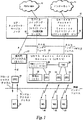
本発明を、図1に示されたUniversal Mobile Telecommunications System(UMTS)10の、制限的でない例の文脈で説明する。雲12として示された、代表的なコネクション指向の外部コア・ネットワークは、たとえば、公衆交換電話網(PSTN)またはサービス総合ディジタル網(ISDN)もしくはその両方とすることができる。雲14として示された、代表的なコネクションレス指向外部コア・ネットワークは、たとえばインターネットとすることができる。両方のコア・ネットワークが、対応するサービス・ノード16に結合される。PSTN/ISDNコネクション指向ネットワーク12は、回路交換サービスを提供するモバイル・スイッチング・センタ(MSC)ノード18として示されたコネクション指向サービス・ノードに接続される。既存のGSMモデルでは、MSC18が、インターフェースAを介して基地局サブシステム(BSS)22に接続され、BSS22は、インターフェースA’を介して無線基地局23に接続される。インターネット・コネクションレス指向ネットワーク14は、パケット交換型サービスを提供するように調整されたGeneral Packet Radio Service(GPRS)ノード20に接続される。コア・ネットワーク・サービス・ノード18および20のそれぞれが、radio access network(RAN)インターフェースを介してUMTS Radio Access Network(URAN)24に接続される。URAN24には、1つまたは複数の無線ネットワーク・コントローラ26が含まれる。各RNC26は、複数の基地局(BS)28と、URAN24内の他のRNCとに接続される。
The present invention will be described in the context of a non-limiting example of the Universal Mobile Telecommunications System (UMTS) 10 shown in FIG. A typical connection-oriented external core network, shown as
好ましい実施形態では、無線アクセスが、広帯域符号分割多重多元接続(WCDMA)に基づき、個々の無線チャネルが、CDMA拡散コードを使用して割り振られる。WCDMAは、マルチメディア・サービスおよび他の高速需要のための広い帯域幅、ならびに高品質を保証するためのダイバーシティ・ハンドオフ(diversity handoff)およびRAKE受信器などの堅牢な機能を提供する。各移動局24は、基地局20がその特定の移動局からの送信を識別するため、ならびに移動局が同一区域内に存在する他の送信および雑音からその移動局にあてられた基地局からの送信を識別するために、それ自体のスクランブリング・コードを割り当てられる。ダウンリンク(BSからMSへ)ブロードキャスト・チャネルおよびアップリンク(MSからBSへ)ランダム・アクセス・チャネルが、図示されている。 In the preferred embodiment, wireless access is based on wideband code division multiple access (WCDMA), and individual wireless channels are allocated using CDMA spreading codes. WCDMA provides robust capabilities such as diversity handoff and RAKE receivers to ensure wide bandwidth for multimedia services and other high-speed demands, and high quality. Each mobile station 24 receives from the base station that was assigned to that mobile station by the base station 20 to identify transmissions from that particular mobile station and from other transmissions and noise that the mobile station is in the same area. To identify the transmission, it is assigned its own scrambling code. The downlink (BS to MS) broadcast channel and the uplink (MS to BS) random access channel are illustrated.
本発明を使用することができるCDMA無線局トランシーバ30を、機能ブロック図形式で図2に示す。当業者は、本発明に関係しない、CDMAトランシーバで使用される他の無線トランシーバ機能が、図示されていないことを諒解するであろう。送信ブランチでは、送信される情報ビットが、拡散器32によって受け取られ、拡散器32が、拡散コード生成器40によって生成される拡散コードに従って、使用可能な周波数スペクトル上でこれらの情報ビットを拡散する(広帯域CDMAの場合、この周波数帯域は、たとえば、5MHz、10MHz、15MHz、またはそれ以上である)。コントローラ44が、コード生成器40によって供給される拡散コードのどれを拡散器32に供給するかを決定する。コード生成器40によって供給される拡散コードは、CMDA通信システムの無線チャネルに対応する。非常に多数のコード・シンボル(「チップ」と称する場合もある)を使用して、各情報ビットをコード化することができるので(WCDMAシステムなどの可変データ・レート・システムでの現在のデータ・レートに依存する)、拡散動作によって、データ・レートがかなり高くなり、これによって、信号帯域幅が広がる。拡散信号は、変調器34に供給され、変調器34は、拡散信号でRF搬送波を変調する。発振器42が、コントローラ44によって選択された周波数の、適当な無線周波数搬送波を生成する。変調されたRF信号は、アンテナ38によって無線インターフェースを介して送信される前に、RF処理ブロック36内でフィルタリングされ、増幅される。
A CDMA
類似するが逆の動作が、トランシーバ30の受信ブランチで実行される。RF信号が、アンテナ38によって受信され、RF処理ブロック150でフィルタリングされる。処理された信号を、発振器44によって供給される適当なRF搬送波信号を使用して、RF復調器48内でRF復調して、RF搬送波から複素ベースバンド信号を抽出する。通常、受信信号を実数(I)直交成分および虚数(Q)直交成分に分解するために、RF復調器内で直交ダウンコンバータが使用される。この形で、チャネル・フェージングまたは送信器発振器と受信器発振器の間の位相非同期に起因する着信信号の位相シフトを検出し、補償することができる。RF復調された複素ベースバンド信号は、同期を得るためにプリアンブル・シーケンスと相関され、その後、ベースバンド受信器46内で、逆拡散コードに従って逆拡散される。
A similar but reverse operation is performed at the receive branch of
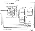
図3を参照すると、ベースバンド受信器46が詳細に示されている。同期プリアンブルは、バイナリ・シーケンスであり、プリアンブルマッチドフィルタ/相関器51に、2つの同一のバイナリ・プリアンブル相関器が含まれ、その一方(52)は、受信したベースバンド信号のIブランチを相関させ、他方(53)は、同一の信号のQブランチを相関させる。プリアンブル・シーケンスは、プリアンブルマッチドフィルタ51に組み込まれ、逆拡散コードは、コード生成器40によって生成される。
Referring to FIG. 3, the baseband receiver 46 is shown in detail. The synchronization preamble is a binary sequence and the preamble matched filter /
受信された複素ベースバンド・プリアンブル信号は、着信信号との正確な同期を達成するため、およびベースバンド(RAKE)復調器57で使用され、後に追跡されるフェージング・チャネル係数の初期値を得るために、対応する同期プリアンブル相関器51内で相関される。タイミング情報は、実数相関器52および虚数相関器53からの絶対相関値を閾値と比較することによって、ピーク検出器54内で得られる。ピーク検出器54は、受信した信号のさまざまなマルチパス成分の遅延(受信器タイミングに対する相対的な)を提供する。タイミング・ユニット56は、この情報を使用して、マルチパス成分の組合せおよびベースバンド(RAKE)復調器での復調の前に、マルチパス成分の相互遅延を補償する。検出された相関ピークに対応する複素相関値が、初期チャネル推定器55に保管され、ベースバンド復調器57で、打ち消される初期フェージング・チャネル係数として使用される。
The received complex baseband preamble signal is used in the baseband (RAKE) demodulator 57 to achieve accurate synchronization with the incoming signal and to obtain an initial value of the fading channel coefficient that is tracked later. Are correlated in the corresponding
本発明では、シーケンスの相補ペアからの1つまたは複数の同期パターンとして使用する。シーケンスの相補ペアの基本特性は、それらの非周期的自己相関関数の合計が、すべての非0タイム・シフトについて0になることである。好ましい例の実施形態では、同期シーケンスが、バイナリ相補シーケンスすなわちゴーレイ相補シーケンスに基づく。有利なことにゴーレイ相補シーケンスは、すべての長さL=2N(Nは任意の正の整数)について構成することができ、長さ10および26についても構成でき、これらの長さの任意の組合せについても構成できる。長いシーケンス長の可能性を有することのほかに、多くのゴーレイ相補シーケンスは、低い非周期的自己相関副ローブを有する。以下の文章では、説明のみの目的でゴーレイ相補シーケンスに焦点を合わせるが、本発明の多くの態様に、任意の相補シーケンスのペアに属するすべてのシーケンスが含まれる。
In the present invention, it is used as one or more synchronization patterns from a complementary pair of sequences. The basic characteristic of a complementary pair of sequences is that their aperiodic autocorrelation function sums to zero for all non-zero time shifts. In a preferred example embodiment, the synchronization sequence is based on a binary complementary sequence or Golay complementary sequence. Advantageously, the Golay complementary sequence can be constructed for all lengths L = 2 N (N is any positive integer), can be constructed for
シーケンスの長さがL=2Nである場合に、シーケンスの多相相補ペアを構成する一般的な方法があり、シーケンスのゴーレイ相補ペアは、特殊なバイナリの場合すなわち2相である。その一般的な構成は、次の再帰関係によって定義される。 There is a general way of constructing a multiphase complementary pair of sequences when the length of the sequence is L = 2N , and the Golay complementary pair of the sequence is a special binary case or two-phase. Its general configuration is defined by the following recursive relationship:
a0(k)=δ(k)
b0(k)=δ(k)
an(k)=an−1(k)+Wn・bn−1(k−Dn)
bn(k)=an−1(k)−Wn・bn−1(k−Dn) (1)
ここで、
k=0,1,2,...,2N−1
n=1,2,...,N
Dn=2Pn
であり、
an(k)およびbn(k)は、長さ2Nの2つの相補シーケンスであり、
δ(k)は、クロネッカのデルタ関数であり、
kは、タイム・スケールを表す整数であり、
nは、反復回数であり、
Dnは、遅延であり、
Pn、n=1,2,...,Nは、数{0,1,2,...,N−1}の任意の置換であり、
Wnは、単位大きさの任意の複素数である。
a 0 (k) = δ (k)
b 0 (k) = δ (k)
a n (k) = a n−1 (k) + W n · b n−1 (k−D n )
b n (k) = a n−1 (k) −W n · b n−1 (k−D n ) (1)
here,
k = 0, 1, 2,. . . , 2 N -1
n = 1, 2,. . . , N
D n = 2 Pn
And
a n (k) and b n (k) are two complementary sequences of
δ (k) is the Kronecker delta function,
k is an integer representing a time scale,
n is the number of iterations,
D n is the delay,
P n , n = 1, 2,. . . , N is a number {0, 1, 2,. . . , N-1}
W n is an arbitrary complex number having a unit size.
Wnが+1または−1の値を有する場合に、バイナリ(ゴーレイ)相補シーケンスが得られる。すべての可能な置換Pnおよびすべての2N個の異なるベクトルWn、(n=1,2,...,N)を使って、N!2N個の異なる相補ペアを構成することが可能である。しかし、長さ2Nの異なるゴーレイ・シーケンスの数は、N!2N−1である。 When W n has a value of +1 or −1, a binary (Golay) complementary sequence is obtained. Using all possible permutations P n and all 2 N different vectors W n , (n = 1, 2,..., N), N! 2 N different complementary pairs can be constructed. However, the number of different Golay sequences of length 2N is N! 2 N-1 .
遅延が、式(1)で定義されているように2の電力ではない場合、または、すべての重みづけ係数Wnが同一の大きさを有するのでない場合には、式(1)の構成によって、マルチレベルの相補ペアが作られる。しかし、本発明の多くの態様は、マルチレベルの相補ペアにも適用される。 If the delay is not a power of 2 as defined in equation (1), or if not all weighting factors W n have the same magnitude, then the configuration of equation (1) Multi-level complementary pairs are created. However, many aspects of the invention also apply to multilevel complementary pairs.
相補ペアからの両方のシーケンスan(k)およびbn(k)の同時生成のための一般的な再帰方式を、図4に示す。図4に示された再帰ゴーレイ・シーケンス生成器60は、式(1)で定義された相補ゴーレイ・シーケンスan(k)およびbn(k)の対を作るが、特に長いコードの場合に、大量のメモリ手段を必要とする。たとえば、長さL=4096、N=12のシーケンスの場合、12個の遅延線(D1ないしD12)が必要であり、最初の遅延線が、D1個のメモリ手段を有し、第2の遅延線が、D2個のメモリ手段を有し、以下同様である。したがって、メモリ手段の総数は、L−1=2N−1になる。というのは、式(1)によれば、
D1+D2+...+Dn=1+2+4+...+2N−1=2N−1
になるからである。ゴーレイ相補シーケンスを生成するためのより効率的な(したがって、好ましいが必要ではない)手段を、これから説明する。
A general recursion scheme for the simultaneous generation of both sequences a n (k) and b n (k) from a complementary pair is shown in FIG. The recursive
D 1 + D 2 +. . . + D n = 1 + 2 + 4 +. . . +2 N-1 = 2 N -1
Because it becomes. A more efficient (and therefore preferred but not necessary) means for generating Golay complementary sequences will now be described.
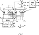
図5に示された直接ゴーレイ相補シーケンス生成器は、図4に示された再帰ゴーレイ・シーケンス生成器60と正確に同一のゴーレイ相補シーケンスのペアを作る。直接ゴーレイ・シーケンス生成器70には、0から2N−1までの循環カウントを可能にするN個のメモリ手段だけを含むモジュロ2Nカウンタ72が含まれる。カウンタ72並列出力は、正の整数変数kのバイナリ表現に対応し、ここで、
The direct Golay complementary sequence generator shown in FIG. 5 creates exactly the same Golay complementary sequence pairs as the recursive

である。置換器74が、N個の並列出力B1(k)ないしBn(k)を受け取るように結合され、これらのN個の並列出力を、1からNまでの範囲の整数のある置換に従って置換する。置換器74で使用される置換ベクトルは、式(1)で使用される置換のすべての数に1を加算することによって得られる。N−1個のANDゲートの第1組76が、置換器74の隣接する出力の対からN−1個の並列出力を作る。第1合計器80が、ANDゲートの第1組76によって生成された出力の2を法とする合計をとる。ANDゲートの第2組78が、置換器74の出力のそれぞれと、式(1)で使用されたバイナリ・ベクトルWnを使用して、1を0に、−1を1に写像することによって得られるN個の重みづけ係数W1 ’ないしWn ’の組の1つとの論理積をとる。第2合計器82が、ANDゲートの第2組78によって生成された出力の2を法とする合計をとる。第3加算器84が、第1加算器と第2加算器の出力の2を法とする合計をとって、バイナリ・シーケンスの相補ペアの第1のバイナリ・シーケンスを作る。第4合計器86が、第3加算器84と、置換器74の最上位出力すなわちBP(N)(k)の2を法とする合計をとって、シーケンスの相補ペアの第2バイナリ・シーケンスを作る。写像器88が、アルファベット{0,1}からの要素を有する第1および第2のバイナリ・シーケンスを、アルファベット{−1,1}からの対応する要素に変換する。
It is. A permuter 74 is coupled to receive N parallel outputs B 1 (k) through B n (k), and replaces these N parallel outputs according to a permutation with an integer ranging from 1 to N. To do. The permutation vector used in permuter 74 is obtained by adding 1 to all the numbers of permutations used in equation (1). A
直接ゴーレイ相補シーケンス生成器70は、メモリ効率がよく、かなり低い複雑さすなわち、従来の線形フィードバック・シフトレジスタ・シーケンス(mシーケンス)生成器に類似する複雑さを有する。これらの特色によって、生成器70が、移動体端末のランダム・アクセス・バースト送信器内および基地局送信器内のシーケンス生成器として特に魅力的になっている。
The direct Golay
受信器側で、完全なシーケンスを受信した時を正確に検出するために、受信されたスペクトラム拡散信号を、送信されたゴーレイ相補シーケンスと相関させなければならない。送信されたゴーレイ相補シーケンスは、最小の非周期的自己相関を有するように選択されるので、検出された最大相関値が自己相関主ローブに対応する確度は、非常に高い。任意の同期シーケンスに整合された相関器90の一般的な簡単な実施形態を、図6に示す。
In order to accurately detect when a complete sequence is received at the receiver side, the received spread spectrum signal must be correlated with the transmitted Golay complementary sequence. Since the transmitted Golay complementary sequence is selected to have minimal aperiodic autocorrelation, the accuracy with which the detected maximum correlation value corresponds to the autocorrelation main lobe is very high. A general simple embodiment of a
受信信号r(k)が、L−1個のメモリ手段を有する遅延線に供給される。各入力信号および各メモリ手段ステージが、a(L−1)、a(L−2)、a(L−3)、...、a(0)によって表されるシーケンスとの相関のために、L個の乗算器への入力を提供する。乗算器の出力を合計して、相関出力信号R(τ)を供給する。ゴーレイ相関器90は、相関を実行するには満足なものであるが、メモリおよびデータ処理に関して非常にコストが高い。たとえば、L=4096の場合に、4095個のメモリ手段、4096個の乗算器、および4095個の合計器が必要である。 The received signal r (k) is supplied to a delay line having L-1 memory means. Each input signal and each memory means stage is a (L-1), a (L-2), a (L-3),. . . , A (0) provides the inputs to the L multipliers for correlation with the sequence represented by a (0). The multiplier outputs are summed to provide a correlation output signal R (τ). The Golay correlator 90 is satisfactory for performing correlations, but is very expensive in terms of memory and data processing. For example, if L = 4096, 4095 memory means, 4096 multipliers, and 4095 summers are required.
したがって、本発明の好ましい実施形態では、図7に示された、効率的なゴーレイ相関器(EGC)100を使用する。機能的には、効率的なゴーレイ相関器100は、式(1)によって定義される相補シーケンスaN(k)およびbN(k)に直接に対応するマッチドフィルタである。この相関器100を特に魅力的にしているものは、図6に示された一般的な相関器90に必要なものよりかなり少ないメモリおよびデータ処理動作を使用することである。
Accordingly, the preferred embodiment of the present invention uses an efficient Golay correlator (EGC) 100, shown in FIG. Functionally, the efficient Golay correlator 100 is a matched filter that directly corresponds to the complementary sequences a N (k) and b N (k) defined by equation (1). What makes this
効率的なゴーレイ相関器100は、入力信号r(k)の、2つの相補シーケンスaN(k)およびbN(k)との相関を同時に実行する。2つのマッチドフィルタ相関器出力Rra(τ)およびRrb(τ)が、対応する非周期的相互相関関数すなわち、受信した信号r(k)が2つのシーケンスaN(k)およびbN(k)と一致する度合を表す値である。マッチドフィルタ/相関器100は、式(1)で定義された重みづけ係数Wnの複素共役、Wn *を使用する。
The efficient Golay correlator 100 performs the correlation of the input signal r (k) with two complementary sequences a N (k) and b N (k) simultaneously. The two matched filter correlator outputs R ra (τ) and R rb (τ) have a corresponding aperiodic cross-correlation function, ie, the received signal r (k) has two sequences a N (k) and b N ( k) is a value representing the degree of coincidence. The matched filter /
したがって、効率的なゴーレイ相関器100は、各ステージが第1および第2の並列処理ブランチを有するN個の直列に連結された処理ステージを使用して、受信したスペクトラム拡散信号r(k)を長さL=2Nのゴーレイ相補シーケンスのペアと相関させる。各処理ステージの第1処理ブランチに供給される入力信号Ra (n−1)(k)が、対応する遅延線Dn(n=1,...,N)の第1メモリ手段に保管され、同一の遅延線Dnの最後のメモリ手段の内容が、同一の処理ステージの加算器(第1ブランチ内)および減算器(第2ブランチ内)に入力される。同一ステージの第2処理ブランチに供給される入力信号Rb (n−1)(k)は、乗算器内で対応する重みづけ係数Wn *をかけられるが、この重みづけ係数Wn *は、式(1)で定義された重みづけ係数Wnの複素共役である。乗算器の出力は、減算器の負入力および第1ブランチの加算器に入力される。加算器の出力Ra (n)(k)は、次の連続するステージの遅延線に入力される。減算器の出力Rb (n)(k)は、次の連続するステージの乗算器に入力される。第1処理ステージの第1処理ブランチおよび第2処理ブランチへの入力信号Ra (0)(k)およびRb (0)(k)は、受信したスペクトラム拡散信号r(k)に対応する。 Thus, the efficient Golay correlator 100 uses the N serially connected processing stages, each stage having first and second parallel processing branches, to receive the received spread spectrum signal r (k). Correlate with a pair of Golay complementary sequences of length L = 2N . The input signal R a (n−1) (k) supplied to the first processing branch of each processing stage is stored in the first memory means of the corresponding delay line D n (n = 1,..., N). is, the contents of the last memory means of the same delay line D n is input to the same processing stage of the adder (in the first branch) and the subtracter (the second branch). The input signal R b (n−1) (k) supplied to the second processing branch of the same stage is multiplied by a corresponding weighting factor W n * in the multiplier, which weighting factor W n * is , The complex conjugate of the weighting coefficient W n defined by Equation (1). The output of the multiplier is input to the negative input of the subtracter and the adder of the first branch. The output R a (n) (k) of the adder is input to the delay line of the next successive stage. The output R b (n) (k) of the subtracter is input to the multiplier of the next successive stage. The input signals R a (0) (k) and R b (0) (k) to the first and second processing branches of the first processing stage correspond to the received spread spectrum signal r (k).
第N処理ステージの第1処理ブランチの出力によって、受信したスペクトラム拡散信号とシーケンスのゴーレイ相補ペアの第1シーケンスan(k)との相互相関Rra(k)が作られる。第N処理ステージの第2処理ブランチの出力によって、受信したスペクトラム拡散信号とシーケンスのゴーレイ相補ペアの第2シーケンスbn(k)との相互相関Rrb(k)が作られる。 The output of the first processing branch of the N processing stages, the cross-correlation R ra (k) is made of a first sequence a n of Golay complementary pair of spread-spectrum signals and the received sequence (k). The output of the second processing branch of the Nth processing stage creates a cross-correlation R rb (k) between the received spread spectrum signal and the second sequence b n (k) of the Golay complementary pair of sequences.
EGCでの乗算の回数は、log2(L)に等しい。対照的に、図6に示されたゴーレイ・シーケンス相関器の簡単なマッチドフィルタ実施形態90は、2・Lに対応するはるかに多数の乗算を必要とする。簡単な実施形態90が、相補ペアの相関に2つの相関器を必要とするが、効率的なゴーレイ相関器100が、相補ペアを同時に相関させることに留意されたい。効率的なゴーレイ相関器100での加算の回数は、2・log2(L)であり、簡単なマッチドフィルタ実施形態90の場合(2・(L−1)になる)より少ない。効率的なゴーレイ相関器100に必要なメモリ手段の数は、L−1であるが、図6に示された一般的な相関器90は、シーケンスの対の相関のために(2(L−1))個のメモリ手段を2組必要とする。したがって、効率的なゴーレイ相関器100では、ICスペースが節約され、処理演算が減らされ、電力が節約され、コストが減らされる。
The number of multiplications in EGC is equal to log 2 (L). In contrast, the simple matched
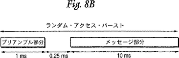
本発明は、移動局が基地局に対応するランダム・アクセス・チャネルを介してメッセージを送信する時に移動局と基地局の間の同期を提供する、特に有利な制限的でない応用分野を有する。そのようなランダム・アクセス・チャネルの1つの例のフォーマットを、図8Aおよび図8Bに関して説明する。ランダム・アクセス・チャネル・フォーマットは、移動局が、特定のフレーム境界に対する複数の明瞭に定義された時間オフセットでランダム・アクセス・チャネル上で送信を行うことができる、スロット付きアロハ(slotted ALOHA)手法に基づく。異なる時間オフセットが、アクセス・スロットとして図示され、1.25ミリ秒だけ離隔する。現在のセルでどのアクセス・スロットが使用可能であるかに関する情報が、ダウンリンク・ブロードキャスト・チャネル上で基地局によってブロードキャストされる。フレーム境界も、現在のセルのブロードキャスト・チャネルによって定義される。ランダム・アクセス・バーストに、2つの部分すなわち、1ミリ秒の長さを有するプリアンブル部分と、10ミリ秒の長さを有するメッセージ部分が含まれる。プリアンブルとメッセージの間に、たとえば0.25ミリ秒のアイドル時間期間をおくことができ、これによって、プリアンブルの検出(相関)およびメッセージの後続のオンライン処理が可能になる。 The present invention has a particularly advantageous non-limiting application that provides synchronization between a mobile station and a base station when the mobile station transmits a message over a random access channel corresponding to the base station. One example format for such a random access channel is described with respect to FIGS. 8A and 8B. The random access channel format is a slotted ALOHA technique that allows a mobile station to transmit on a random access channel with multiple clearly defined time offsets for a particular frame boundary. based on. Different time offsets are illustrated as access slots and are separated by 1.25 milliseconds. Information regarding which access slots are available in the current cell is broadcast by the base station on the downlink broadcast channel. Frame boundaries are also defined by the broadcast channel of the current cell. The random access burst includes two parts: a preamble part having a length of 1 millisecond and a message part having a length of 10 milliseconds. There can be an idle time period of, for example, 0.25 milliseconds between the preamble and the message, which allows for preamble detection (correlation) and subsequent online processing of the message.
移動局によって実行されるランダム・アクセス手順を、図9に示されたランダム・アクセス(MS)ルーチン(ブロック200)に関して説明する。当初、移動局は、特定の基地局呼に対する同期を獲得しなければならない(ブロック210)。背景で説明したように、移動局は、この初期同期化を、最も低いパス損失を有する基地局のセル検索中に実行する。移動局は、基地局ブロードキャスト・チャネルに同調し、ブロードキャスト信号を処理して、同期シーケンスを検出する。1つの例の実施形態では、同期化が、2つのステップに分解される。第1ステップでは、移動体が、すべての基地局に共通の主同期シーケンスを検出する。最も強い相関または最大の相関を検出した後に、移動局は、第2ステップを実行し、この第2ステップでは、移動局が、この基地局に特有の第2同期シーケンスを相関させる。 The random access procedure performed by the mobile station will be described with respect to the random access (MS) routine (block 200) shown in FIG. Initially, the mobile station must acquire synchronization for a particular base station call (block 210). As explained in the background, the mobile station performs this initial synchronization during cell search for the base station with the lowest path loss. The mobile station tunes to the base station broadcast channel, processes the broadcast signal, and detects the synchronization sequence. In one example embodiment, synchronization is broken down into two steps. In the first step, the mobile detects a main synchronization sequence common to all base stations. After detecting the strongest correlation or the maximum correlation, the mobile station performs a second step, in which the mobile station correlates a second synchronization sequence specific to this base station.
特定のセルへの同期を獲得した後に、移動局は、ダウンリンク・ブロードキャスト・チャネルから、この特定のセルで使用されるランダム・アクセス・プリアンブル拡散コードおよびメッセージ・スクランブリング・コードに関する情報を、使用可能なプリアンブル・シグネチャ、使用可能なランダム・アクセス・チャネル・アクセス・スロット、および他の情報に関する情報と共に獲得する(ブロック220)。その後、移動局は、使用可能なものからアクセス・タイム・スロットおよびシグネチャを選択する(ブロック230)。その後、移動局は、選択されたアクセス・タイム・スロット中に、シグネチャおよびプリアンブル拡散コードを使用してランダム・アクセス・バーストを生成する(ブロック240)。 After obtaining synchronization to a particular cell, the mobile station uses information about the random access preamble spreading code and message scrambling code used in this particular cell from the downlink broadcast channel. Obtained along with information about possible preamble signatures, available random access channel access slots, and other information (block 220). The mobile station then selects an access time slot and signature from those available (block 230). The mobile station then generates a random access burst using the signature and preamble spreading code during the selected access time slot (block 240).
移動局によって送信されたランダム・アクセス・バーストは、図10に流れ図形式で示されたランダム・アクセス(BS)ルーチン(ブロック300)と共に説明するように、基地局で受信され、正しく相関されなければならない。基地局は、コンポジットRF信号を受信し、その信号をベースバンドに変換し、ベースバンド信号を1つまたは複数のプリアンブル・シーケンスと相関させる(ブロック310)。具体的に言うと、基地局は、マッチドフィルタ・タイプの相関器を使用して、ベースバンド・コンポジット信号をプリアンブル・シーケンスと相関させる(ブロック320)。その後、最大相関ピークを検出し、これを使用して、フレーム、スロット、およびチップの同期タイミング情報を推定する。ピーク検出器(たとえば54)が、受信した信号のさまざまなマルチパス成分の相対(受信器タイミングに対する)遅延を供給する(ブロック330)。推定されたタイミング情報を、ランダム・アクセス・チャネル・バーストのメッセージ部分の復調のためにRAKEコンバイナ(たとえば57)に供給する(ブロック340)。タイミング・ユニット(たとえば56)が、RAKE復調器(たとえば57)での組合せおよび復調の前に、マルチパス成分の相互遅延を補償する。検出された相関ピークに対応する複素相関値を、RAKE復調器で打ち消される初期フェージング・チャネル係数として使用する。 Random access bursts transmitted by the mobile station must be received and correctly correlated at the base station, as described with the random access (BS) routine (block 300) shown in flow diagram form in FIG. Don't be. The base station receives the composite RF signal, converts the signal to baseband, and correlates the baseband signal with one or more preamble sequences (block 310). Specifically, the base station uses a matched filter type correlator to correlate the baseband composite signal with the preamble sequence (block 320). The maximum correlation peak is then detected and used to estimate frame, slot, and chip synchronization timing information. A peak detector (eg, 54) provides a relative (relative to receiver timing) delay of the various multipath components of the received signal (block 330). The estimated timing information is provided to a RAKE combiner (eg, 57) for demodulation of the message portion of the random access channel burst (block 340). A timing unit (eg 56) compensates for the multipath component mutual delay prior to combination and demodulation in the RAKE demodulator (eg 57). The complex correlation value corresponding to the detected correlation peak is used as the initial fading channel coefficient that is canceled by the RAKE demodulator.
図11に示されたランダム・アクセス・チャネル(RACH)プリアンブル相関器400は、使用するメモリの量に関して特に効率的である。効率性は、シグネチャ・バイナリ・シーケンスとプリアンブル拡散コードを直列に(階層的に)連結することによって達成される。すなわち、シグネチャ・シーケンスの各バイナリ・ビットが、同一のプリアンブル拡散コードによって拡散される。受信信号は、マッチドフィルタ410内で、たとえばTmax=256チップの長さを有する、プリアンブル拡散コードと相関される。マッチドフィルタ410によって作られる中間相関値は、乗算器420で、たとえば16の長さを有するシグネチャ・シーケンス(ブロードキャスト・チャネルを介して基地局によって供給される)の要素をかけられる。合計器430が、乗算器420の出力と、マッチドフィルタの長さ、たとえば256と同一の要素数を有する遅延線420の出力と合計する。合計器430の出力は、遅延線440に入力され、ピーク検出器450に供給される。プリアンブル相関器400は、受信信号r(k)の期待される遅延τが、|τ|<Tmaxになるように制限され、Tmaxが、プリアンブル拡散コードの長さであるという条件の下で、望み通りに動作する。
The random access channel (RACH)
相関演算は、その間にランダム・アクセス・バーストが受信されると期待されるタイム・ウィンドウ、たとえば256チップと同期化される。このタイム・ウィンドウの長さは、移動局が基地局とのダウンリンク同期または主同期を既に達成していることが前提になっている。連続する256チップ・ウィンドウのそれぞれについて、そのウィンドウについてマッチドフィルタ410によって生成される256個の相関値に、16シンボル長のシグネチャ・シーケンスの1シンボルをかける。その後、シグネチャ・シーケンスの次のシンボルを、次の256チップ・タイム・ウィンドウの開始時に選択する。乗算された相関値を、前のタイム・ウィンドウ内の同一の相対時間位置で実行された前の合計の結果と合計する。前の合計の結果は、遅延線440の出力から得られ、その後、現在の合計の結果が、遅延線440に保管される。ピーク検出器450に出力される最終相関値は、16個のタイム・ウィンドウすなわち、256チップ・タイム・ウィンドウ内の各時間位置での合計の16回の繰り返しの後に供給される。したがって、反復のそれぞれで、値256の中間相関ピークが積分されるので、完全な相関ピークは4096に等しくなる。ピーク検出器450は、I受信器ブランチおよびQ受信器ブランチの両方から相関値を受け取り、絶対相関値または自乗絶対相関値を計算する。ピーク検出器450は、たとえば図3に示されたRACH受信器の残りに接続される。
The correlation operation is synchronized with the time window during which random access bursts are expected to be received, eg, 256 chips. The length of this time window assumes that the mobile station has already achieved downlink synchronization or main synchronization with the base station. For each successive 256 chip window, the 256 correlation values generated by the matched
RACHプリアンブル相関器400は、従来の相関器よりかなり少ないメモリを必要とするので、特に効率的である。たとえば、L=4096の場合、RACHプリアンブル相関器400は、511個のメモリ手段だけを必要とするが、図6に示された一般的な相関器90は、4095個のメモリ手段を必要とする。
The
プリアンブル相関器400の構造のメモリ削減の利益は、図12に示された、図11に示されたものに類似する構造を有するメモリ効率のよいゴーレイ・シーケンス相関器500の実施に有利に使用される。相関器500では、必要な加算および乗算の数が減っている。図12に示された効率的なゴーレイ相関器500は、長さL=2N=J・Tmaxのゴーレイ・シーケンスの、2つのより短い長さTmaxの構成要素相補シーケンスA(k)およびB(k)の関数としての表現に基づく。この関数は、シーケンスの相補ペアの式(1)での一般的な再帰構成の結果である。すなわち、一般的な再帰構成が、相補シーケンスの任意の対から開始される場合、すなわち、初期ベクトルa0(k)およびb0(k)が、
a0(k)=A(k)
b0(k)=B(k), k=0,1,2,...,Tmax−1
になるように選択され、A(k)およびB(k)が、長さTmaxの2つの相補シーケンスである場合に、結果の長さL=2N=J・Tmaxの相補シーケンスのペアが、J回の反復の後に生成される。式(1)のすべての遅延Dnが、構成要素シーケンスの長さ(Tmax)をかけられる。
The memory reduction benefits of the structure of the
a 0 (k) = A (k)
b 0 (k) = B (k), k = 0, 1, 2,. . . , T max −1
Is chosen to be, A (k) and B (k) is, in the case of two complementary sequences of length T max, the result of the length L = 2 N = J · T max pair complementary sequence Is generated after J iterations. All delays D n in equation (1) are multiplied by the length of the component sequence (T max ).
受信された信号r(k)は、たとえば長さL=256チップを有する、図7に示された効率的なゴーレイ相関器510によって受け取られることが好ましい。効率的なゴーレイ相関器510は、シーケンスのゴーレイ相補ペアに対応する2つの相互相関値RrA(τ)およびRrB(τ)を生成する。スイッチまたはセレクタ520が、この2つの相関値を受け取る。「インターリービング信号」と称する制御信号が、セレクタ520を制御して、「0」が供給される場合にはRrA(τ)相関値、「1」が供給される場合にはRrB(τ)相関を選択する。これによって、セレクタ520が、インターリーブ化シーケンスの現在の値に基づいて、連続するタイム・ウィンドウのそれぞれの間の相関値の中間対の1つを交互に供給する。より短い構成要素シーケンスの連結の順序は、インターリーブ化シーケンスによって決定される。シグネチャが長さ16を有するこの例のインターリーブ化シーケンスは、やはり16に等しい長さを有する。セレクタ520の出力は、乗算器420で、乗算器420内の現在の256チップ・タイミング・ウィンドウに対応するシグネチャのシンボルの1つをかけられる。乗算器420、合計器430、遅延線440、およびピーク検出器450で実行される動作は、図11に関して説明したものに類似する。図11からの方式の場合と同様に、メモリ効率のよいゴーレイ相関器400は、受信信号r(k)の期待される遅延τが、|τ|<Tmaxになるように制限され、Tmaxが、構成要素相補シーケンスの長さであるという条件の下で、望み通りに動作する。
The received signal r (k) is preferably received by an efficient Golay correlator 510 shown in FIG. 7, for example having a length L = 256 chips. The efficient Golay correlator 510 generates two cross-correlation values R rA (τ) and R rB (τ) corresponding to the Golay complementary pairs of the sequence. A switch or
相関器500は、図11の相関器400と同数のメモリ手段を有するが、乗算器と加算器の数はそれよりかなり少ない。図11のマッチドフィルタ・プリアンブル拡散コード相関器410の代わりに使用されるEGC510のより高い効率のゆえに、総合効率が改善される。
The
より高い容量が望ましいセルでは、複数の同期シーケンスの組を構成することが有用である。より多くの同期シーケンスによって、より多くの容量の可能性がもたらされる。そのような組のシーケンスは、相互相関を最小にするために直交であることが好ましい。本発明は、式(1)の再帰構成からのゴーレイ・シーケンスの直交する組の効率的な生成を提供する。 In cells where higher capacity is desired, it is useful to construct multiple synchronization sequence sets. More synchronization sequences offer more capacity possibilities. Such a set of sequences is preferably orthogonal to minimize cross-correlation. The present invention provides for efficient generation of orthogonal sets of Golay sequences from the recursive construction of equation (1).
直交ゴーレイ・シーケンスの組は、置換Pnのそれぞれについて、すなわち、遅延Dnの組のそれぞれについて、長さNのL/2=2N−1個のベクトルW(v,n)の適当な組すなわち、v=0,1,...,2N−1−1およびn=1,2,3,...,Nを選択することによって、式(1)から生成することができる。各ベクトルW(v,n)によって、相補ゴーレイ・シーケンスの対が作られる。その結果、合計2N個のシーケンスが、長さ2Nのゴーレイ・シーケンスの直交の組で提供される。 For each permutation P n , ie, for each set of delays D n , the set of orthogonal Golay sequences is an appropriate number of L / 2 = 2 N−1 vectors W (v, n) of length N A set, i.e., v = 0, 1,. . . , 2 N−1 −1 and n = 1, 2, 3,. . . , N can be generated from equation (1). Each vector W (v, n) creates a pair of complementary Golay sequences. As a result, a total of 2 N sequences are provided in an orthogonal set of 2 N Golay sequences.
式(1)からゴーレイ・シーケンスの直交の組を作る長さNの2N−1個のベクトルW(v,n)の組は、たとえば、2つの異なる形で生成することができる。第1のアルゴリズムは、 A set of 2 N-1 vectors W (v, n) of length N that make an orthogonal set of Golay sequences from equation (1) can be generated, for example, in two different ways. The first algorithm is
であり、ここで、Bn(x)は、ある正整数xのNビット長バイナリ表現の第nビットすなわち、 Where B n (x) is the nth bit of an N-bit binary representation of a positive integer x, ie
である。第2のアルゴリズムは、次式によって与えられる。 It is. The second algorithm is given by
以下の例示的な例を検討されたい。長さL=8=23、N=3のゴーレイ・シーケンスの直交の組を、式(1)を使用して得ると仮定する。数{0,1,2}の任意の置換P={P0,P1,P2}から始めて、P={0,2,1}であるものとする。長さ3の必要な重みづけベクトルW(v,n)は、式(2a)から得られ、これを次の表1に示す。
Consider the following illustrative example. Assume that an orthogonal set of Golay sequences of length L = 8 = 2 3 and N = 3 is obtained using equation (1). Let P = {0,2,1}, starting with an arbitrary permutation P = {P 0 , P 1 , P 2 } of the number {0,1,2}. The required weight vector W (v, n) of
結果の直交の長さ8のゴーレイ・シーケンスの組S(u,k)を、表2に示す。 The resulting orthogonal length 8 Golay sequence set S (u, k) is shown in Table 2.
対応する4相コードを得るために、各ゴーレイ・シーケンスに、定数複素数(1+j)/√2、(ここでj=√−1)をかけることができる。 Each Golay sequence can be multiplied by a constant complex number (1 + j) / √2, where j = √−1 to obtain the corresponding four-phase code.
RACHプリアンブルに対する直交ゴーレイ・シーケンスの特定の有利な応用例を、図13に示されたメモリ効率のよいゴーレイ相関器に関して説明する。図13に、複数のプリアンブル・シーケンスを使用することができるRACHプリアンブル相関器600を実施する、本発明の好ましい例の実施形態を示す。図13の相関器のバンク内に示された32個の相関器のそれぞれが、図12に示された相関器500に類似する形で動作する。構成要素シーケンスが、Tmax=256の長さであり、置換ベクトルPn、および重みづけ付けベクトルWnが、16の長さである場合に、相補ペアの各シーケンスの結果の全長は、4096になる。シーケンスA(k)およびB(k)からなる結果のゴーレイ・シーケンスは、8回繰り返され、これが、置換ベクトルPnに依存する「インターリービング」関数を使用して、セレクタ520によって多重化される。インターリービング関数I0(k)が、最初の16個の直交プリアンブルに共通であり、インターリービング関数I1(k)が、残りの16個の直交プリアンブルに共通である。各プリアンブルは、独自の「シグネチャ」シーケンスを有し、このシグネチャ・シーケンスは、重みづけ関数Wnおよび置換ベクトルPnに依存する。インターリービング関数によって、送信されたプリアンブルの構造に従って、EGCの一方または他方の出力が選択される。
A particular advantageous application of orthogonal Golay sequences for the RACH preamble is described with respect to the memory efficient Golay correlator shown in FIG. FIG. 13 illustrates a preferred example embodiment of the present invention implementing a RACH preamble correlator 600 that can use multiple preamble sequences. Each of the 32 correlators shown in the correlator bank of FIG. 13 operates in a manner similar to
長さ256の共通の構成要素シーケンスA(k)およびB(k)(および共通のインターリービング関数)を有する、長さ4096の16個のゴーレイ・シーケンスの第1の直交の組は、長さ16の単一の置換ベクトルを、式(2)による8つの重みづけベクトルと共に選択することによって得られる。式(1)のすべての遅延Dnに、構成要素シーケンスの長さ(Tmax=256)をかける。
The first orthogonal set of 16 Golay sequences of length 4096, having 256 common component sequences A (k) and B (k) (and a common interleaving function) is the
同一の構成要素シーケンスA(k)およびB(k)を有するが、もう1つのインターリービング関数I1(k)に従ってもう1つのセレクタ610によってインターリーブされる、長さ4096の追加の16個の直交ゴーレイ・シーケンスは、下記によって得られる。
An additional 16 orthogonals of length 4096 that have the same component sequence A (k) and B (k) but are interleaved by another
a0(k)=B(k)
b0(k)=A(k), k=0,1,2,...,Tmax−1
直交ゴーレイ・シーケンスの追加の組を得るために式(1)で使用される置換ベクトルおよび重みづけベクトルは、直交ゴーレイ・シーケンスの第1の組と同一である。合計で、長さ256の共通する構成要素シーケンスを有する長さ4096の32個の直交ゴーレイ・シーケンスがある。一般に、J=L/Tmaxであるものとして、2J個のそのような直交ゴーレイ・シーケンスを生成することが可能である。
a 0 (k) = B (k)
b 0 (k) = A (k), k = 0, 1, 2,. . . , T max −1
The permutation and weighting vectors used in equation (1) to obtain an additional set of orthogonal Golay sequences are the same as the first set of orthogonal Golay sequences. In total, there are 32 orthogonal Golay sequences of length 4096 with 256 common component sequences of length. In general, it is possible to generate 2J such orthogonal Golay sequences, where J = L / T max .
これらのインターリービング関数およびシグネチャ関数を、上の表1および表2で与えられるものと同一の例を使用する長さ8のゴーレイ・シーケンスの直交の組によって示す。Tmax=2であり、構成要素シーケンスがA(k)={1,1}およびB(k)={1,−1}である場合に、表2で与えられたシーケンスの組を、表3に示されるように表すことができる。 These interleaving and signature functions are shown by orthogonal sets of length 8 Golay sequences using the same example given in Tables 1 and 2 above. If T max = 2 and the component sequences are A (k) = {1,1} and B (k) = {1, −1}, the set of sequences given in Table 2 is 3 can be expressed.
インターリービング関数I0(k)およびI1(k)は、
I0(k)={0,0,1,1}およびI1(k)={1,1,0,0}
であり、ここで、「0」の値によって、シーケンスA(k)との相互相関が選択され、「1」の値によって、シーケンスB(k)との相互相関が選択される。したがって、インターリービング関数I1(k)は、I0(k)を反転した版である。最初の4つの「シグネチャ」関数を下に示す。
The interleaving functions I 0 (k) and I 1 (k) are
I 0 (k) = {0,0,1,1} and I 1 (k) = {1,1,0,0}
Here, the cross-correlation with the sequence A (k) is selected by the value of “0”, and the cross-correlation with the sequence B (k) is selected by the value of “1”. Therefore, the interleaving function I 1 (k) is a version obtained by inverting I 0 (k). The first four “signature” functions are shown below.
シグネチャ0={1,1,1,−1}、シグネチャ1={1,−1,1,1}、
シグネチャ2={1,1,−1,1}、シグネチャ3={1,−1,−1,−1}
他の4つのシグネチャ関数の値は、同一すなわち、シグネチャ4=シグネチャ0、シグネチャ5=シグネチャ1、シグネチャ6=シグネチャ2、およびシグネチャ7=シグネチャ3である。
The values of the other four signature functions are identical: signature 4 =
本発明の前の例の応用例は、移動局によって送信されたランダム・アクセス・バーストを受信し、同期化するために基地局によって使用される1つまたは複数の相関器に対するものである。前に述べた本発明のもう1つの例の有利な応用例は、移動局内で使用されるセル検索相関器に対するものである。初期セル検索中に、移動局は、最も低いパス損失を有する基地局を検索する。その後、移動局は、基地局のタイム・スロットおよびフレーム同期と、基地局に関連するダウンリンク・スクランブリング・コードを判定する。初期セル検索は、3ステップすなわち、(1)スロット同期化、(2)フレーム同期化およびコード・グループ識別、および(3)スクランブリング・コード識別で行われる。この、本発明の他の非制限的な例の応用例は、第1および第2のステップ(1)および(2)に関する。 An application of the previous example of the present invention is for one or more correlators used by a base station to receive and synchronize random access bursts transmitted by a mobile station. An advantageous application of another example of the present invention described above is for a cell search correlator used in a mobile station. During the initial cell search, the mobile station searches for the base station with the lowest path loss. The mobile station then determines the base station time slot and frame synchronization and the downlink scrambling code associated with the base station. The initial cell search is performed in three steps: (1) slot synchronization, (2) frame synchronization and code group identification, and (3) scrambling code identification. This other non-limiting example application of the invention relates to the first and second steps (1) and (2).
移動局でのスロット同期化手順では、各タイム・スロットの先頭ですべての基地局によってブロードキャストされる、すべての基地局に共通の主同期コードを使用する。同期化手順は、着信信号を主同期コードと相関させることからなる。相関器の出力によって、移動局の範囲内の各基地局からの各放射線のピークが生成される。最も強いピークの位置を検出することによって、最も強い基地局の、タイム・スロット長を「法」とするタイミングが与えられる。 The slot synchronization procedure at the mobile station uses a main synchronization code common to all base stations that is broadcast by all base stations at the beginning of each time slot. The synchronization procedure consists of correlating the incoming signal with the main synchronization code. The correlator output generates a peak for each radiation from each base station within range of the mobile station. By detecting the position of the strongest peak, the timing of the strongest base station with the time slot length as “modulus” is given.
スロット同期化は、移動局の観点からはクリティカルなステップである。というのは、この動作が、移動局がある他の基地局へのリンクを既に有する場合であっても、常時実行されるからである。したがって、主同期コードに関する移動局の相関器の実装の複雑さは、可能であれば最小にしなければならない。そのような最小化は、主同期コードの特殊な構造を利用することによって達成することができる。その一方で、主同期化コードは、移動局が所望の主ローブではなく副ローブに同期する可能性を最小にするために、最小の非周期的自己相関副ローブを有しなければならない。 Slot synchronization is a critical step from the mobile station perspective. This is because this operation is always performed even if the mobile station already has a link to some other base station. Therefore, the complexity of the mobile station correlator implementation for the primary synchronization code should be minimized if possible. Such minimization can be achieved by utilizing a special structure of the main synchronization code. On the other hand, the main synchronization code must have a minimum aperiodic autocorrelation sidelobe to minimize the possibility that the mobile station will synchronize to the sidelobe rather than the desired mainlobe.
セル検索主同期コードに関するこの後者の要件は、その開示が参照によって本明細書に組み込まれる、本願の譲受人に譲渡された米国特許出願第09/135247号明細書、表題「Communication Methods and Apparatus Based on Orthogonal Hadamard−Based Sequences Having Selected Autocorrelation Properties」、1998年8月17日出願で提案されているように、ゴーレイ相補シーケンスを使用することによって満たすことができる。その特許出願書では、最初のセル検索ステップで使用する、ゴーレイ相補シーケンスに基づく主同期コードのマッチドフィルタリングの効率的な方法が指定されていない。幸い、本発明は、主同期コードとしてゴーレイ相補シーケンスを使用する効率的な実施形態を提供する。 This latter requirement for the cell search primary synchronization code is described in US patent application Ser. No. 09/135247, entitled “Communication Methods and Apparatus Based”, the disclosure of which is incorporated herein by reference. It can be met by using Golay complementary sequences, as proposed in “Orthogonal Hadamard-Based Sequences Having Selected Autocorrelation Properties”, August 17, 1998. The patent application does not specify an efficient method for matched filtering of the main synchronization code based on the Golay complementary sequence used in the initial cell search step. Fortunately, the present invention provides an efficient embodiment that uses Golay complementary sequences as the primary synchronization code.
図7に示されたEGC100に類似する効率的なゴーレイ相関器を、セル検索の第1ステップで主同期コード相関器として使用することによって、たとえば階層主同期コードに整合された図11に示された相関器400に類似する階層相関器(HC)より大きい実施の利益がもたらされる。長さ256の階層コードは、UTRAシステムの1提案に含まれるように、長さ16の2つの構成要素シーケンスの、直列すなわち階層的な連結によって得られる。好ましい実施形態では、主同期コードの長さが、256チップである。長さ256のゴーレイ相補シーケンスは、最小の最大絶対非周期的自己相関副ローブ(MAS)値を有するので、主セル検索コードとしての応用に最適である。長さ256のすべてのゴーレイ相補シーケンスについて得られた最小MAS値は、12である。MAS=12を有するゴーレイ・シーケンスの対の1つが、次式によって定義される。
By using an efficient Golay correlator similar to the
Pn={6,3,7,2,1,4,0,5}およびWn={1,−1,−1,1,1,−1,1,1} (3)
EGCのメモリ・ビット数Nmemは、各遅延線のメモリ・セルの数と、最初の遅延線の後で、メモリ・セル・ワード長が、新しい遅延線ごとに1つ増えるという事実を考慮することによって計算することができる。受信信号の1ビット量子化を前提にすると、次のようになる。
P n = {6, 3, 7, 2, 1, 4, 0, 5} and W n = {1, -1, -1,1,1, -1,1,1} (3)
The number of memory bits N mem in EGC takes into account the number of memory cells in each delay line and the fact that after the first delay line, the memory cell word length is increased by one for each new delay line. Can be calculated by Assuming 1-bit quantization of the received signal, it is as follows.
Nmem (EGC)=1・26+2・23+3・27+4・22+5・21+6・24+7・20+8・25=849
階層相関器(HC)は、長さ16の1つの簡単な相関器と、長さ16の15個の遅延線を必要とする。そのような遅延線のそれぞれのメモリ・セル・ワード長は、5ビットである。したがって、このHCについて、Nmem (HC)=1・16+(5・16)・15=1216である。
N mem (EGC) = 1 · 2 6 + 2 · 2 3 + 3 · 2 7 + 4 · 2 2 + 5 · 2 1 + 6 · 2 4 + 7 · 2 0 + 8 · 2 5 = 849
A hierarchical correlator (HC) requires one simple correlator of
EGCによって相関されたゴーレイ相補シーケンスは、階層シーケンスに対する下記の利点を提供する。
・加算器の数が、HCの30個に対してEGCでは16個である。
・乗算器の数が、HCの32個に対してEGCでは8個である。
・メモリ・ビットの数が、EGCではHCの場合より30%少ない。
・ゴーレイ相補シーケンスでは、非周期的自己相関副ローブの最大絶対値が、階層シーケンスの1/3である。
A Golay complementary sequence correlated by EGC provides the following advantages over hierarchical sequences:
-The number of adders is 16 for EGC compared to 30 for HC.
The number of multipliers is 8 in EGC compared to 32 in HC.
-The number of memory bits is 30% less in EGC than in HC.
In the Golay complementary sequence, the maximum absolute value of the aperiodic autocorrelation sidelobe is 1/3 of the hierarchical sequence.
本発明のもう1つの例の実施形態では、因数分解された効率的なゴーレイ相関器を提供する。長さ256のそのような相関器を、図14に示す。因数分解された形で表されたゴーレイ・シーケンスは、たとえば長さ64の、2つのより短い構成要素(相補)シーケンスの連結として構成することができる。その場合に、相関器700に、図7に示されたものに類似する、長さ64の効率的なゴーレイ相関器710、長さ64の遅延線720、730、740、および750、乗算器790、および加算器760、770、および780が含まれる。乗算器の総数は、多くとも10であり、加算器の総数は、15に等しい。加算器の数が、長さ256のEGCの場合より1つ少ないことに留意されたい。遅延線の実際の数は、インターリーブ化シーケンスに依存する。
In another example embodiment of the present invention, a factorized efficient Golay correlator is provided. Such a correlator of
相関器700は、受信器局部発振器の可干渉時間がシーケンス長より短い(たとえば、多くとも64チップである)時に有用になる可能性がある。その結果、中間相関値の最適下限の非コヒーレント積分が必要である。言い換えると、相関器700を用いると、中間相関値のコヒーレントおよび非コヒーレントの両方の積分が可能になる。図14の例の相関器700は、コヒーレントである。この例では、長さ256のゴーレイ・シーケンスが、{−B,B,A,A}と表され、ここで、AおよびBは、長さ64の相補シーケンスである。
セル検索の第2ステップでは、長さ256チップの17個の第2同期コード(SSC)の組を使用することができる。SSCは、主同期コード(PSC)に対して直交しなければならない。主同期コードが、本発明の1つの例の応用例によるゴーレイ相補シーケンスであると仮定すると、17個の直交SSCの組を生成する方法の1つが、その開示を参照によって本明細書に組み込まれる、本願の譲受人に譲渡された米国特許出願第09/135247号明細書、表題「Communication Methods and Apparatus Based on Orthogonal Hadamard−Based Sequences Having Selected Autocorrelation Properties」、1998年8月17日出願で提案されている。SSCの直交の組は、PSCに同一の長さの17個の異なるウォルシュ(Walsh)関数をかけることによって生成される。そのようなSSCの組を用いると、実装の複雑さを減らすために、セル検索の第2ステップで高速アダマール(Hadamard)変換(FHT)プロセッサを使用することができるようになる。さらに、PSCが、ゴーレイ相補シーケンスである場合に、そのゴーレイPSCに異なるウォルシュ関数をかけることによって得られるシーケンスの組が、ゴーレイ・シーケンスの直交の組をもたらす。この場合、これらのSSCを、上で説明した主同期コード相関手順に類似するEGCのバンクを使用して検出することもできる。本発明によるそのようなEGCのバンクは、必要な動作の数に関して、FHTに基づく相関よりも効率的である。
In the second step of cell search, a set of 17 second synchronization codes (SSCs) of
SSCに関する追加要件は、第2同期コードから主同期コード相関器への干渉を最小にするために、PSCと17個のSSCのそれぞれとの間の非周期的相互相関を小さくすることである。この場合では、式(2)を使用して長さ256チップの256個の直交ゴーレイ・シーケンスの完全な組を生成し、これらのゴーレイ・シーケンスの1つを主同期コードとして選択し、その後、それぞれが、ある適度な閾値未満の、主同期コードとの最大絶対非周期的相互相関を有する、17個の第2同期コードを選択することが有利である。たとえば、PSCが、式(1)および(3)によって生成されたa(k)シーケンスであると仮定すると、42の閾値以下のPSCとの最大絶対非周期的相互相関を有する17個のSSCの組は、式(3)と同一の置換ベクトルと、下記の重みづけベクトルによって定義される。
An additional requirement for the SSC is to reduce the aperiodic cross-correlation between the PSC and each of the 17 SSCs in order to minimize interference from the second synchronization code to the main synchronization code correlator. In this case, Equation (2) is used to generate a complete set of 256 orthogonal Golay sequences of
WSSC1={ 1 1 1 −1 1 1 −1 1}、(a)
WSSC2={ 1 −1 1 −1 −1 −1 1 1}、(b)
WSSC3={−1 1 1 −1 −1 1 1 1}、(b)
WSSC4={−1 1 1 −1 −1 −1 −1 1}、(a)
WSSC5={−1 1 −1 1 1 −1 1 1}、(b)
WSSC6={−1 −1 1 −1 −1 1 1 1}、(b)
WSSC7={−1 −1 1 −1 −1 −1 −1 1}、(a)
WSSC8={−1 −1 −1 1 1 1 1 1}、(b)
WSSC9={−1 −1 −1 1 1 −1 1 1}、(a)
WSSC10={−1 −1 −1 1 1 −1 −1 1}、(a)
WSSC11={−1 −1 −1 1 −1 −1 1 1}、(b)
WSSC12={−1 −1 −1 1 −1 −1 −1 1}、(a)
WSSC13={−1 −1 −1 1 −1 −1 −1 1}、(b)
WSSC14={−1 −1 −1 −1 1 1 1 1}、(a)
WSSC15={−1 −1 −1 −1 1 1 −1 1}、(a)
WSSC16={−1 −1 −1 −1 −1 1 1 1}、(a)
WSSC17={−1 −1 −1 −1 −1 1 −1 1}、(a)
(4)
対応するシーケンスSSCnは、重みつけベクトルWSSCnが(1)で置換される時に、ゴーレイ・シーケンスa(k)またはb(k)に等しい((4)では、各ベクトルに付加された括弧内に示されている)。SSCは、PSCの場合と同様に、17個(またはそれ未満)のEGCの対応するバンクを使用して検出することができる。
W SSC1 = {1 1 1 -1 1 1 -1 1}, (a)
W SSC2 = {1 -1 1 -1 -1 -1 1 1}, (b)
W SSC3 = {− 1 1 1 −1 −1 1 1 1 1}, (b)
W SSC4 = {− 1 1 1 −1 −1 −1 −1 1}, (a)
W SSC5 = {− 1 1 −1 1 1 −1 1 1}, (b)
W SSC6 = {− 1 −1 1 −1 −1 1 1 1 1}, (b)
W SSC7 = {− 1 −1 1 −1 −1 −1 −1 1}, (a)
W SSC8 = {− 1 −1 −1 1 1 1 1 1 1}, (b)
W SSC9 = {− 1 −1 −1 1 1 −1 1 1}, (a)
W SSC10 = {− 1 −1 −1 1 1 −1 −1 1}, (a)
W SSC11 = {-1 -1 -1 1 -1 -1 1 1}, (b)
W SSC12 = {− 1 −1 −1 1 −1 −1 −1 1}, (a)
W SSC13 = {− 1 −1 −1 1 −1 −1 −1 1}, (b)
W SSC14 = {− 1 −1 −1 −1 1 1 1 1 1}, (a)
W SSC15 = {− 1 −1 −1 −1 1 1 −1 1}, (a)
W SSC16 = {− 1 −1 −1 −1 −1 1 1 1 1}, (a)
W SSC17 = {− 1 −1 −1 −1 −1 1 −1 1}, (a)
(4)
The corresponding sequence SSCn is equal to the Golay sequence a (k) or b (k) when the weighting vector W SSCn is replaced by (1) (in (4), in parentheses attached to each vector. It is shown). SSC can be detected using the corresponding bank of 17 (or less) EGCs as in the case of PSC.
改良された実装効率に加えて、ゴーレイ相補ペアシーケンスに基づく同期コードは、たとえば連結された直交ゴールド・シーケンスに基づく同期シーケンスと比較して、最大絶対非周期的自己相関副ローブ(MAS)に関して優れた性能を提供する。この比較を、図15および図16のグラフによって示す。図15は、直列に連結された直交ゴールド・シーケンスの非周期的自己相関関数のグラフである。0遅延に対応するサンプルに実質的な最大値があるが、さまざまな非0遅延に、誤った相関検出を引き起こす可能性があるかなりの最大ピークもあることに留意されたい。対照的に、図16のグラフでは、ゴーレイ相補ペアシーケンスに基づく同期コードについて、副ローブがはるかに低く、ランダム・アクセス検出に重要な範囲(すなわち、主ローブから±255チップ)内で、副ローブが他の部分よりさらに低いことが示されている。 In addition to improved implementation efficiency, synchronization codes based on Golay complementary pair sequences are superior in terms of maximum absolute aperiodic autocorrelation sidelobes (MAS) compared to synchronization sequences based on, for example, concatenated orthogonal gold sequences Provide performance. This comparison is illustrated by the graphs in FIGS. FIG. 15 is a graph of the aperiodic autocorrelation function of orthogonal Gold sequences connected in series. Note that there is a substantial maximum in samples corresponding to zero delay, but there are also significant maximum peaks at various non-zero delays that can cause false correlation detection. In contrast, in the graph of FIG. 16, for the synchronization code based on the Golay complementary pair sequence, the side lobe is much lower and within the range important for random access detection (ie, ± 255 chips from the main lobe). Is shown to be even lower than the rest.
ランダム・アクセス・プリアンブルとしての直交ゴーレイ相補シーケンスの適用に関して、その非周期的自己相関特性を、一般的なプリアンブル拡散コードを用いる直交シグネチャの直列連結によって得られる直交プリアンブルの別の組のそれと比較することが重要である。比較のパラメータは、組のプリアンブルのそれぞれの最大絶対非周期的自己相関副ローブ(MAS)である。現在開発中のUTRAシステムを対象とする、この例の比較では、本発明による長さ4096の16個の直交ゴーレイ・シーケンスの組を、直交ゴールド・シーケンスに基づくRACHプリアンブルに関するもう1つのUTRA提案と比較する。表4に、長さ256の、2つのより短い構成要素相補シーケンスA(k)およびB(k)の関数としての16個のゴーレイ・シーケンスを示す。
Compare the aperiodic autocorrelation property with that of another set of orthogonal preambles obtained by serial concatenation of orthogonal signatures using a general preamble spreading code with respect to the application of orthogonal Golay complementary sequences as random access preambles This is very important. The parameter of comparison is the maximum absolute aperiodic autocorrelation sidelobe (MAS) of each of the set of preambles. In this example comparison for a UTRA system currently under development, a set of 16 orthogonal Golay sequences of length 4096 according to the present invention is compared with another UTRA proposal for a RACH preamble based on an orthogonal gold sequence. Compare. Table 4 shows 16 Golay sequences as a function of two shorter component complementary sequences A (k) and B (k) of
この構成要素ゴーレイ・シーケンスA(k)およびB(k)は、置換
Pn={0,2,1,5,6,4,7,3}
および重みづけ
Wn={1,−1,1,−1,1,−1,−1,1}
を使用して、式(1)から得られる。
This component Golay sequence A (k) and B (k) is replaced by the substitution P n = {0, 2, 1, 5, 6, 4, 7, 3}.
And weighting W n = {1, -1,1, -1,1, -1, -1,1}
Is obtained from equation (1).
上で定義した16個の直交ゴーレイ・シーケンスの組のMAS値と、UTRAに関するもう1つの提案に記載された一般的なプリアンブル拡散コード(プリアンブル拡散コード数n=1)によって拡散された16個の直交シグネチャから得られる16個の連結された直交ゴールド・シーケンスの組のMAS値を、表5に示す。 The 16 MAS values of the set of 16 orthogonal Golay sequences defined above and the 16 preambles spread by the general preamble spreading code (preamble spreading code number n = 1) described in another proposal for UTRA The MAS values for the set of 16 concatenated orthogonal gold sequences obtained from the orthogonal signature are shown in Table 5.
前に説明したように、ランダム・アクセス・プリアンブルは、移動端末が基地局タイミングに関する基本情報を既に有するので、基地局受信器に対して完全に非同期ではないが、基地局と移動端末の間のラウンドトリップ伝搬遅延によって導入される不確実性がある。適度な仮定の1つが、ラウンドトリップ遅延が多くとも255チップであり、したがって、ランダム・アクセス・プリアンブルの非周期的自己相関関数が、実際には、主ローブから±255チップの領域でのみ重要であるということである。主ローブから±255チップの領域内の非周期的自己相関副ローブの最大絶対値を、前に説明した長さ4096の直交ゴーレイ・シーケンスおよび連結された直交ゴールド・シーケンスについて、表6に示す。 As explained previously, the random access preamble is not completely asynchronous to the base station receiver, since the mobile terminal already has basic information about the base station timing, but between the base station and the mobile terminal. There is uncertainty introduced by round-trip propagation delay. One reasonable assumption is that the round trip delay is at most 255 chips, so the aperiodic autocorrelation function of the random access preamble is actually only important in the region of ± 255 chips from the main lobe. That is. The maximum absolute value of the aperiodic autocorrelation sidelobe in the region of ± 255 chips from the main lobe is shown in Table 6 for the previously described length 4096 orthogonal Golay sequence and the concatenated orthogonal Gold sequence.
表6には、直交ゴーレイ・シーケンスが、主ローブから±255チップの領域で、連結された直交ゴールド・シーケンスより25倍低い自己相関副ローブを有することが示されている。 Table 6 shows that the orthogonal Golay sequence has an autocorrelation side lobe that is 25 times lower than the concatenated orthogonal gold sequence in the region of ± 255 chips from the main lobe.
特定の実施形態に関して本発明を説明してきたが、当業者は、本発明が、本明細書で説明され図示された特定の実施形態に制限されないことを諒解するであろう。図示され説明されたもの以外の異なるフォーマット、実施形態、および適応ならびに多数の修正、変形、および同等の配置を使用して、本発明を実施することもできる。したがって、本発明をその好ましい実施形態に関して説明してきたが、この開示が、例示的であるのみであって、決して制限的ではなく、単に本発明の例示であることを理解されたい。 Although the present invention has been described in terms of particular embodiments, those skilled in the art will appreciate that the invention is not limited to the specific embodiments described and illustrated herein. The invention can also be implemented using different formats, embodiments, and adaptations as well as numerous modifications, variations, and equivalent arrangements other than those shown and described. Thus, while the invention has been described with reference to preferred embodiments thereof, it is to be understood that this disclosure is illustrative only and is in no way limiting, but merely illustrative of the invention.
Claims (2)
スペクトラム拡散信号を受信し、成分相補シーケンスに対応する相関値の中間値のペアを生成する長さXの第1の相関器と、
長さY=L/Xのインタリーブ・シーケンスの現在値に基づいて連続する時間範囲のそれぞれで前記中間値のペアの一方を交互に供給し、その要素は集合{0,1}に属し、前記成分相補シーケンスの連結順序は前記インタリーブ・シーケンスによって決定される第1の選択器と、
選択された前記中間値に前記シグネチャ・シーケンスの要素を乗算して、乗算された相関出力を生成する乗算器と、
乗算された相関出力とX個のメモリ手段を備える遅延ラインのフィードバック出力とを合計し、得られた合計を前記遅延ラインへの入力として供給する合計器を備え、
最終的に得られる相関値が、Y個の連続する時間範囲の後で得られた合計に対応していることを特徴とする相関器。 A correlator for determining a correlation of a received spread spectrum signal transmitted by a second transceiver using one of a sequence from a pair of complementary sequences of length L = 2 N at a first transceiver, wherein N Is an arbitrary positive integer, where one sequence is represented as a concatenation of two short component complementary sequences of length X, each component sequence being L / X times according to a signature sequence of length Y = L / X It is repeated and modulated by +1 or -1,
A first correlator of length X that receives the spread spectrum signal and generates an intermediate pair of correlation values corresponding to the component complementary sequence;
Alternately supplying one of said pairs of intermediate values in each successive time range based on the current value of an interleaved sequence of length Y = L / X, whose elements belong to the set {0, 1}, A first selector in which the concatenation order of the component complementary sequences is determined by the interleaved sequence;
A multiplier for multiplying the selected intermediate value by an element of the signature sequence to produce a multiplied correlation output;
Summing the multiplied correlation output and the feedback output of the delay line with X memory means and providing the resulting sum as an input to said delay line;
Correlator characterized in that the finally obtained correlation value corresponds to the sum obtained after Y consecutive time ranges.
長さXの2つの短い成分相補シーケンスA(k)およびB(k)の連結として一方のゴーレイ相補シーケンスを表現し、各成分相補シーケンスはL/X回反復され、かつ長さY=L/Xのシグネチャ・シーケンスに従って+1または−1だけ変調され、連結の順序が要素を0または1とする長さY=L/Xのインタリーブ・シーケンスによって決定されるステップであって、
スペクトラム拡散信号を受信し、前記ゴーレイ相補シーケンスの成分相補シーケンスに対応する相関値の中間値のペアを生成する長さXのゴーレイ相関器を使用するステップと、
前記ゴーレイ相関器の第1の相関出力での相関値の中間値を、Y=(L/X)−1以下の直列に連結された、X個のメモリ手段を備えた遅延ラインの第1のグループに格納するステップと、
前記ゴーレイ相関器の第2の相関出力での相関値の中間値を、Y=(L/X)−1以下の直列に連結された、X個のメモリ手段を備えた遅延ラインの第2のグループに格納するステップと、
前記第1の相関器の出力と前記遅延ラインの第1のグループの出力に、元のバージョンのシグネチャ・シーケンスのそれぞれの要素を乗算するステップと、
前記第1の相関出力と元のバージョンのインタリーブ・シーケンスにおける0でない要素に対応した前記遅延ラインから得られた乗算された相関値の中間値のみと、前記第2の相関器の出力と前記インタリーブ・シーケンスの反転バージョン及び元のバージョンの0でない要素に対応した前記遅延ラインからの乗算された相関値の中間値のみを合計し、前記元のバージョンのインタリーブ・シーケンスにおける第1の要素が相関器出力に対応し、前記インタリーブ・シーケンスの最後の要素がカスケード配列の最後の遅延ラインの出力に対応するステップと、
最終的な相関値として前記合計による結果を出力するステップと
を含む方法。 Spread spectrum transmitted and received by the second transceiver using a sequence contained in a pair of Golay complementary sequences of length L = 2 N , where N is any positive integer, at the first transceiver A method for obtaining a correlation value of a signal,
Express one Golay complementary sequence as a concatenation of two short component complementary sequences A (k) and B (k) of length X, each component complementary sequence repeated L / X times, and length Y = L / Modulated by +1 or -1 according to a signature sequence of X, the order of concatenation determined by an interleaved sequence of length Y = L / X with elements 0 or 1,
Using a Golay correlator of length X that receives a spread spectrum signal and generates an intermediate pair of correlation values corresponding to component complementary sequences of the Golay complementary sequence;
The intermediate value of the correlation values at the first correlation output of the Golay correlator is a first of the delay lines with X memory means connected in series with Y = (L / X) −1 or less. Storing in a group;
The intermediate value of the correlation values at the second correlation output of the Golay correlator is the second of the delay lines with X memory means connected in series with Y = (L / X) −1 or less. Storing in a group;
Multiplying the output of the first correlator and the output of the first group of delay lines by respective elements of the original version of the signature sequence;
Only the intermediate value of the multiplied correlation values obtained from the delay line corresponding to non-zero elements in the first correlation output and the original version of the interleaving sequence, the output of the second correlator and the interleaving Sum only the intermediate values of the multiplied correlation values from the delay line corresponding to the inverted version of the sequence and the non-zero elements of the original version, and the first element in the original version of the interleaved sequence is the correlator Corresponding to an output, the last element of the interleaved sequence corresponding to the output of the last delay line of the cascaded array;
Outputting the result of the sum as a final correlation value.
Applications Claiming Priority (2)
| Application Number | Priority Date | Filing Date | Title |
|---|---|---|---|
| US09/263,106 US6567482B1 (en) | 1999-03-05 | 1999-03-05 | Method and apparatus for efficient synchronization in spread spectrum communications |
| US09/263,106 | 1999-03-05 |
Related Parent Applications (1)
| Application Number | Title | Priority Date | Filing Date |
|---|---|---|---|
| JP2000604540A Division JP2002539667A (en) | 1999-03-05 | 2000-03-03 | Method and apparatus for efficiently acquiring synchronization in spread spectrum communication |
Publications (2)
| Publication Number | Publication Date |
|---|---|
| JP2011234389A JP2011234389A (en) | 2011-11-17 |
| JP5114585B2 true JP5114585B2 (en) | 2013-01-09 |
Family
ID=23000389
Family Applications (3)
| Application Number | Title | Priority Date | Filing Date |
|---|---|---|---|
| JP2000604540A Pending JP2002539667A (en) | 1999-03-05 | 2000-03-03 | Method and apparatus for efficiently acquiring synchronization in spread spectrum communication |
| JP2009260408A Expired - Fee Related JP4505040B2 (en) | 1999-03-05 | 2009-11-13 | Method and apparatus for efficiently obtaining synchronization in spread spectrum communications |
| JP2011130586A Expired - Fee Related JP5114585B2 (en) | 1999-03-05 | 2011-06-10 | Method and apparatus for efficiently obtaining synchronization in spread spectrum communications |
Family Applications Before (2)
| Application Number | Title | Priority Date | Filing Date |
|---|---|---|---|
| JP2000604540A Pending JP2002539667A (en) | 1999-03-05 | 2000-03-03 | Method and apparatus for efficiently acquiring synchronization in spread spectrum communication |
| JP2009260408A Expired - Fee Related JP4505040B2 (en) | 1999-03-05 | 2009-11-13 | Method and apparatus for efficiently obtaining synchronization in spread spectrum communications |
Country Status (11)
| Country | Link |
|---|---|
| US (1) | US6567482B1 (en) |
| EP (1) | EP1159796A2 (en) |
| JP (3) | JP2002539667A (en) |
| KR (1) | KR100726050B1 (en) |
| CN (1) | CN1367965B (en) |
| AR (1) | AR025824A1 (en) |
| AU (1) | AU770399B2 (en) |
| CA (1) | CA2364349C (en) |
| MY (1) | MY123539A (en) |
| TW (1) | TW463477B (en) |
| WO (1) | WO2000054424A2 (en) |
Cited By (1)
| Publication number | Priority date | Publication date | Assignee | Title |
|---|---|---|---|---|
| JP2016535536A (en) * | 2013-09-09 | 2016-11-10 | ホアウェイ・テクノロジーズ・カンパニー・リミテッド | System and method for increasing low density signature space |
Families Citing this family (197)
| Publication number | Priority date | Publication date | Assignee | Title |
|---|---|---|---|---|
| KR20000009140A (en) * | 1998-07-21 | 2000-02-15 | 윤종용 | Apparatus and method for initial capture and frame synchronization of spread spectrum communication system |
| AU3411299A (en) * | 1999-03-08 | 2000-09-28 | Nokia Networks Oy | Method for establishing a communication between a user equipment and a radio network |
| US7643540B2 (en) * | 1999-03-15 | 2010-01-05 | Lg Electronics Inc. | Pilot signals for synchronization and/or channel estimation |
| US7496132B2 (en) * | 1999-03-15 | 2009-02-24 | Kg Electronics Inc. | Pilot signals for synchronization and/or channel estimation |
| KR100294711B1 (en) * | 1999-03-15 | 2001-07-12 | 서평원 | Frame Synchronization Method using Optimal Pilot Symbol |
| US6574267B1 (en) * | 1999-03-22 | 2003-06-03 | Golden Bridge Technology, Inc. | Rach ramp-up acknowledgement |
| US6831929B1 (en) * | 1999-03-22 | 2004-12-14 | Texas Instruments Incorporated | Multistage PN code aquisition circuit and method |
| US7039036B1 (en) * | 1999-04-01 | 2006-05-02 | Texas Instruments Incorporated | Reduced complexity primary and secondary synchronization codes with good correlation properties for WCDMA |
| DE19917337C2 (en) * | 1999-04-16 | 2002-02-28 | Infineon Technologies Ag | Method and device for synchronizing a mobile radio receiver with a frame structure of a radio signal |
| KR100669570B1 (en) * | 1999-04-29 | 2007-01-15 | 지멘스 악티엔게젤샤프트 | A method of synchronizing a base station with a mobile station, a base station, and a mobile station |
| US6958989B1 (en) * | 1999-05-19 | 2005-10-25 | Interdigital Technology Corporation | Uplink scrambling code assignment for a random access channel |
| BR9917317B1 (en) * | 1999-05-26 | 2013-09-17 | "Method and device for random access control in a mobile communication network" | |
| US7103085B1 (en) | 1999-06-18 | 2006-09-05 | Texas Instruments Incorporated | Wireless communications system with secondary synchronization code based on values in primary synchronization code |
| JP4970643B2 (en) * | 1999-06-18 | 2012-07-11 | テキサス インスツルメンツ インコーポレイテッド | Wireless communication system using secondary synchronization code based on value of primary synchronization code |
| JP3322243B2 (en) * | 1999-06-30 | 2002-09-09 | 日本電気株式会社 | Direct spread CDMA receiver |
| CA2276971A1 (en) * | 1999-07-06 | 2001-01-06 | Wen Tong | Preamble using golay sequence for access channel in cellular communications systems |
| GB2352368A (en) * | 1999-07-19 | 2001-01-24 | Oak Technology Inc | Receiver circuit |
| JP4288777B2 (en) * | 1999-08-11 | 2009-07-01 | ソニー株式会社 | Multi-carrier signal transmitter and multi-carrier signal receiver |
| KR100429545B1 (en) * | 1999-08-17 | 2004-04-28 | 삼성전자주식회사 | Method for communicating scrambling code id in mobile communication system |
| GB2386801B (en) * | 1999-08-24 | 2004-03-24 | Roke Manor Research | A method of locating a mobile station within a telecommunications cell forming part of a telecommunications system |
| FR2803467B1 (en) * | 1999-12-30 | 2002-02-08 | Mitsubishi Electric Inf Tech | METHOD OF ESTIMATING A TRANSMISSION OR TELECOMMUNICATION CHANNEL |
| FR2803468B1 (en) * | 1999-12-30 | 2002-04-12 | Mitsubishi Electric Inf Tech | METHOD OF ESTIMATING A TRANSMISSION OR TELECOMMUNICATIONS CHANNEL |
| EP1117186A1 (en) * | 2000-01-14 | 2001-07-18 | Lucent Technologies Inc. | Adaptive code-tracking RAKE receiver for direct-sequence code-division multiple access (cdma) communications |
| EP1117185A1 (en) * | 2000-01-14 | 2001-07-18 | Lucent Technologies Inc. | Method and rake receiver for code-tracking in CDMA communication systems |
| DE10001854A1 (en) * | 2000-01-18 | 2001-08-02 | Infineon Technologies Ag | Method and device for determining the carrier frequency of base stations in the mobile receiver of a cellular mobile radio system working with W-CDMA |
| AU760513B2 (en) * | 2000-02-16 | 2003-05-15 | Samsung Electronics Co., Ltd. | Apparatus and method for assigning a common packet channel in a CDMA communication system |
| EP1130792A1 (en) * | 2000-03-03 | 2001-09-05 | Lucent Technologies Inc. | A method and rake receiver for phasor estimation in communication systems |
| US6778835B2 (en) * | 2000-03-18 | 2004-08-17 | Lg Electronics Inc. | Method for allocating physical channel of mobile communication system and communication method using the same |
| GB0007334D0 (en) * | 2000-03-28 | 2000-05-17 | Koninkl Philips Electronics Nv | Radio communication system |
| ATE261231T1 (en) * | 2000-05-10 | 2004-03-15 | Mitsubishi Electric Inf Tech | METHOD FOR ASSIGNING SECONDARY SYNCHRONIZATION CODES TO A BASE STATION OF A MOBILE COMMUNICATIONS SYSTEM |
| US7400654B2 (en) * | 2000-05-23 | 2008-07-15 | Siemens Aktiengesellschaft | Method for synchronizing a receiver with a transmitter |
| ES2164613B1 (en) * | 2000-08-16 | 2003-05-16 | Fuente Vicente Diaz | METHOD, TRANSMITTER AND RECEIVER FOR DIGITAL SPECTRUM COMMUNICATION ENGAGED THROUGH MODULATION OF COMPLEMENTARY SEQUENCES GOLAY. |
| US8165246B1 (en) * | 2000-08-28 | 2012-04-24 | Alcatel Lucent | Training sequence for low latency LMS implementation |
| US7173899B1 (en) * | 2000-08-28 | 2007-02-06 | Lucent Technologies Inc. | Training and synchronization sequences for wireless systems with multiple transmit and receive antennas used in CDMA or TDMA systems |
| JP3729329B2 (en) * | 2000-09-19 | 2005-12-21 | 株式会社エヌ・ティ・ティ・ドコモ | Cell search method for mobile station in mobile communication system and mobile station in mobile communication system |
| US7154850B1 (en) * | 2000-09-20 | 2006-12-26 | Lucent Technologies Inc. | Wireless data transmission using time out control |
| FR2814877B1 (en) * | 2000-10-02 | 2003-01-03 | Mitsubishi Electric Inf Tech | CHANNEL ESTIMATION SEQUENCE AND METHOD OF ESTIMATING A TRANSMISSION CHANNEL WHICH USES SUCH A CHANNEL ESTIMATION SEQUENCE |
| FR2814885B1 (en) | 2000-10-03 | 2003-05-30 | Mitsubishi Electric Inf Tech | BASE STATION SYNCHRONIZATION METHOD |
| GB0024530D0 (en) * | 2000-10-06 | 2000-11-22 | Roke Manor Research | Use of multiple offsets with concatenated periodically extended complementary sequences |
| US20080095121A1 (en) * | 2002-05-14 | 2008-04-24 | Shattil Steve J | Carrier interferometry networks |
| US8670390B2 (en) | 2000-11-22 | 2014-03-11 | Genghiscomm Holdings, LLC | Cooperative beam-forming in wireless networks |
| US20020097780A1 (en) * | 2000-11-30 | 2002-07-25 | Odenwalder Joseph P. | Preamble generation |
| JP3510589B2 (en) * | 2000-12-15 | 2004-03-29 | Necエレクトロニクス株式会社 | Cell search method and cell search device |
| JP3857528B2 (en) * | 2001-01-12 | 2006-12-13 | 富士通株式会社 | Synchronous detection device |
| JP3346415B2 (en) * | 2001-02-14 | 2002-11-18 | 日本電気株式会社 | Mobile communication system, base station and communication control method |
| US10931338B2 (en) | 2001-04-26 | 2021-02-23 | Genghiscomm Holdings, LLC | Coordinated multipoint systems |
| US9819449B2 (en) | 2002-05-14 | 2017-11-14 | Genghiscomm Holdings, LLC | Cooperative subspace demultiplexing in content delivery networks |
| US10355720B2 (en) | 2001-04-26 | 2019-07-16 | Genghiscomm Holdings, LLC | Distributed software-defined radio |
| US9893774B2 (en) | 2001-04-26 | 2018-02-13 | Genghiscomm Holdings, LLC | Cloud radio access network |
| US10425135B2 (en) | 2001-04-26 | 2019-09-24 | Genghiscomm Holdings, LLC | Coordinated multipoint systems |
| US6836666B2 (en) * | 2001-05-08 | 2004-12-28 | Lucent Technologies Inc. | Method to control uplink transmissions in a wireless communication system |
| DE10124223A1 (en) * | 2001-05-18 | 2002-11-21 | Philips Corp Intellectual Pty | Method and device for synchronizing a radio transmitter with a radio receiver |
| CN1138428C (en) * | 2001-06-11 | 2004-02-11 | 华为技术有限公司 | Method for selecting synchronous code in synchronizing system of mobile communication |
| KR100461545B1 (en) * | 2001-10-20 | 2004-12-16 | 한국전자통신연구원 | Method for Generating and Detecting Synchronisation Codes of Synchronisation Channel |
| US7729412B2 (en) | 2001-10-29 | 2010-06-01 | Qualcomm Incorporated | Parameter estimator with dynamically variable integration time |
| US7308022B2 (en) * | 2001-11-01 | 2007-12-11 | Rick Roland R | Parameter estimator configured to distinguish between peaks and sidelobes of correlation function |
| US7558534B2 (en) | 2001-11-02 | 2009-07-07 | Qualcomm Incorporated | Reliability metrics for parameter estimates which account for cumulative error |
| US7006587B1 (en) * | 2001-11-20 | 2006-02-28 | Cisco Technolgy, Inc. | Preamble aided synchronization |
| US7274759B2 (en) * | 2001-12-21 | 2007-09-25 | Koninklijke Philips Electronics N.V. | Antenna switching based on a preamble MSE metric |
| US7155229B2 (en) * | 2002-01-08 | 2006-12-26 | Ericsson Inc. | Distributed wireless architecture using microcast |
| US7813311B2 (en) * | 2002-02-05 | 2010-10-12 | Interdigital Technology Corporation | Method and apparatus for synchronizing base stations |
| DE60320956D1 (en) * | 2002-03-07 | 2008-06-26 | Alvarion Ltd | HIERARCHICAL PREAMBLE STRUCTURES FOR OFDMA BASED ON COMPLEMENTARY SEQUENCES |
| GB2386444B (en) * | 2002-03-12 | 2004-05-26 | Toshiba Res Europ Ltd | Digital correlators |
| US10142082B1 (en) | 2002-05-14 | 2018-11-27 | Genghiscomm Holdings, LLC | Pre-coding in OFDM |
| US9628231B2 (en) | 2002-05-14 | 2017-04-18 | Genghiscomm Holdings, LLC | Spreading and precoding in OFDM |
| US9225471B2 (en) | 2002-05-14 | 2015-12-29 | Genghiscomm Holdings, LLC | Cooperative subspace multiplexing in communication networks |
| US9270421B2 (en) | 2002-05-14 | 2016-02-23 | Genghiscomm Holdings, LLC | Cooperative subspace demultiplexing in communication networks |
| US10644916B1 (en) | 2002-05-14 | 2020-05-05 | Genghiscomm Holdings, LLC | Spreading and precoding in OFDM |
| US10200227B2 (en) | 2002-05-14 | 2019-02-05 | Genghiscomm Holdings, LLC | Pre-coding in multi-user MIMO |
| US8942082B2 (en) | 2002-05-14 | 2015-01-27 | Genghiscomm Holdings, LLC | Cooperative subspace multiplexing in content delivery networks |
| US9136931B2 (en) | 2002-05-14 | 2015-09-15 | Genghiscomm Holdings, LLC | Cooperative wireless networks |
| ATE484890T1 (en) * | 2002-08-21 | 2010-10-15 | Nxp Bv | DELAY LINE FOR RECEIVING MULTIPLE PROPAGATION PATHS |
| KR100479864B1 (en) * | 2002-11-26 | 2005-03-31 | 학교법인 중앙대학교 | Method and apparatus embodying and synchronizing downlink signal in mobile communication system and method for searching cell using the same |
| KR100905572B1 (en) * | 2002-12-03 | 2009-07-02 | 삼성전자주식회사 | Apparatus and method for generating preamble sequence in communication system using orthogonal frequency division multiplexing |
| EP1443669B1 (en) * | 2003-01-31 | 2017-05-03 | France Brevets | Device for synchronization and codegroup identification |
| US7349461B2 (en) | 2003-02-13 | 2008-03-25 | Qualcomm Incorporated | Efficient back-end channel matched filter (CMF) |
| US20040228424A1 (en) * | 2003-02-27 | 2004-11-18 | Baldwin Keith R. | Receiver with analog barker detector |
| GB0307415D0 (en) * | 2003-03-31 | 2003-05-07 | British Telecomm | Matched filtering |
| KR100770912B1 (en) * | 2003-06-16 | 2007-10-26 | 삼성전자주식회사 | Apparatus and Method for Generating Preamble Sequence in Communication System Using Orthogonal Frequency Division Multiplexing |
| US7684472B2 (en) * | 2003-07-02 | 2010-03-23 | Thomson Licensing | Method and apparatus for frequency-robust detection of a wideband code division multiple access secondary synchronization channel |
| SE0302233D0 (en) * | 2003-08-18 | 2003-08-18 | Infineon Technologies Ag | Sliding window |
| US20050078598A1 (en) * | 2003-08-21 | 2005-04-14 | Anuj Batra | Enhancement to the multi-band OFDM physical layer |
| FR2859025B1 (en) * | 2003-08-22 | 2006-04-21 | Cit Alcatel | METHOD FOR VALIDATING THE DETECTION OF A CORRELATION PIC BY A POSITIONING SYSTEM RECEIVER BY SATELLITE |
| US7508806B1 (en) * | 2003-08-29 | 2009-03-24 | National Semiconductor Corporation | Communication signal processor architecture |
| US20050113141A1 (en) * | 2003-11-20 | 2005-05-26 | Telefonaktiebolaget Lm Ericsson (Publ) | Spatial joint searcher and channel estimators |
| US7308286B2 (en) * | 2003-11-20 | 2007-12-11 | Telefonaktiebolaget Lm Ericsson (Publ) | Multi-dimensional joint searcher and channel estimators |
| US20050113142A1 (en) * | 2003-11-20 | 2005-05-26 | Telefonaktiebolaget Lm Ericsson (Publ) | Temporal joint searcher and channel estimators |
| ES2244304B1 (en) * | 2003-12-17 | 2007-07-01 | Vicente Diaz Fuente | DEVICE AND METHOD FOR THE SYNCHRONIZATION OF A DATA COMMUNICATION SYSTEM BY MEANS OF COMPLEMENTARY SEQUENCES. |
| US7453920B2 (en) * | 2004-03-09 | 2008-11-18 | Atc Technologies, Llc | Code synchronization in CDMA satellite wireless communications system using uplink channel detection |
| WO2005088853A1 (en) | 2004-03-09 | 2005-09-22 | Neocific Inc. | Methods and apparatus for random access in multi-carrier communication systems |
| US7627054B2 (en) * | 2004-04-26 | 2009-12-01 | Vicente Diaz Fuente | Device and method for improving the signal to noise ratio by means of complementary sequences |
| KR100754794B1 (en) * | 2004-05-29 | 2007-09-03 | 삼성전자주식회사 | Cell identification code transmission and reception apparatus and method in mobile communication system |
| US11431386B1 (en) | 2004-08-02 | 2022-08-30 | Genghiscomm Holdings, LLC | Transmit pre-coding |
| US11552737B1 (en) | 2004-08-02 | 2023-01-10 | Genghiscomm Holdings, LLC | Cooperative MIMO |
| US11184037B1 (en) | 2004-08-02 | 2021-11-23 | Genghiscomm Holdings, LLC | Demodulating and decoding carrier interferometry signals |
| KR100702456B1 (en) * | 2004-12-10 | 2007-04-03 | 한국전자통신연구원 | Symbol synchronization detection method and apparatus |
| EP1705825A1 (en) * | 2005-03-23 | 2006-09-27 | Dr. Reinhart Rudershausen | Binary Code Matched Filter for Transceivers |
| CN101273524A (en) * | 2005-08-16 | 2008-09-24 | 伟俄内克斯研究公司 | Frame synchronization |
| US20070064665A1 (en) * | 2005-08-23 | 2007-03-22 | Interdigital Technology Corporation | Method and apparatus for accessing an uplink random access channel in a single carrier frequency division multiple access system |
| US8583995B2 (en) * | 2005-11-16 | 2013-11-12 | Qualcomm Incorporated | Multi-mode processor |
| US8910027B2 (en) * | 2005-11-16 | 2014-12-09 | Qualcomm Incorporated | Golay-code generation |
| US8429502B2 (en) * | 2005-11-16 | 2013-04-23 | Qualcomm Incorporated | Frame format for millimeter-wave systems |
| WO2007066292A2 (en) * | 2005-12-08 | 2007-06-14 | Koninklijke Philips Electronics N.V. | System, apparatus, and method for a robust synchronization scheme for digital communication systems |
| US8064414B2 (en) | 2005-12-13 | 2011-11-22 | Qualcomm, Incorporated | Range extension techniques for a wireless local area network |
| ES2376284T3 (en) | 2005-12-22 | 2012-03-12 | Electronics And Telecommunications Research Institute | PROCEDURE FOR DISCONTINUOUS TRANSMISSION / RECEPTION OPERATION TO REDUCE ENERGY CONSUMPTION IN A CELLULAR SYSTEM. |
| US8000305B2 (en) * | 2006-01-17 | 2011-08-16 | Motorola Mobility, Inc. | Preamble sequencing for random access channel in a communication system |
| CN102325116B (en) * | 2006-01-18 | 2014-06-25 | 华为技术有限公司 | Synchronization method and system in communication system |
| CN102316067B (en) * | 2006-01-18 | 2013-12-04 | 华为技术有限公司 | Synchronization method in communication system and system |
| EP2637318B1 (en) * | 2006-01-18 | 2014-10-01 | Huawei Technologies Co., Ltd. | Method and system for synchronization in a communication system |
| JP4431176B2 (en) * | 2006-02-10 | 2010-03-10 | パナソニック株式会社 | Wireless transmission apparatus and wireless transmission method |
| US20070213067A1 (en) * | 2006-03-09 | 2007-09-13 | Patrick Li | Wireless communication handoffs within a macrocell |
| US8009637B2 (en) * | 2006-03-10 | 2011-08-30 | Motorola Solutions, Inc. | Method and apparatus for spreading channel code selection |
| DE602006015606D1 (en) | 2006-04-04 | 2010-09-02 | Mitsubishi Electric Corp | Method for synchronizing a signal frame in a telecommunication system |
| US7653156B2 (en) * | 2006-04-20 | 2010-01-26 | The Boeing Company | Method for fine timing acquisition |
| JP4240072B2 (en) * | 2006-07-07 | 2009-03-18 | ヤマハ株式会社 | Spread spectrum circuit |
| ES2324688B2 (en) * | 2006-07-20 | 2011-01-17 | Semiconductores Investigacion Y Diseño Sa | METHOD AND SYSTEM OF ESTIMATION OF MULTIPLE CHANNELS INPUT AND MULTIPLE OUTPUT. |
| CN100389552C (en) * | 2006-07-26 | 2008-05-21 | 北京大学 | Timing Estimation Device and Method in Direct Sequence Spread Spectrum Communication System |
| KR100896206B1 (en) * | 2006-08-08 | 2009-05-12 | 삼성전자주식회사 | Resource Allocation Device and Method in Broadband Wireless Communication System |
| US8369860B2 (en) * | 2006-08-18 | 2013-02-05 | Interdigital Technology Corporation | Sending and reducing uplink feedback signaling for transmission of MBMS data |
| KR101043833B1 (en) * | 2006-08-18 | 2011-06-22 | 후지쯔 가부시끼가이샤 | Amble Sequence with New and Legacy Wireless Communication Devices |
| CN101136677B (en) * | 2006-08-28 | 2013-01-30 | 北京信威通信技术股份有限公司 | TDD system base station disturbance null method and system |
| JP4866690B2 (en) * | 2006-09-11 | 2012-02-01 | 富士通株式会社 | Preamble receiver |
| JP4903213B2 (en) | 2006-09-26 | 2012-03-28 | パナソニック株式会社 | Wireless transmission apparatus and wireless transmission method |
| WO2008038367A1 (en) | 2006-09-28 | 2008-04-03 | Fujitsu Limited | Wireless communication apparatus |
| EP2087605B1 (en) * | 2006-10-03 | 2012-03-21 | QUALCOMM Incorporated | Method and apparatus for processing primary and secondary synchronization signals for wireless communication |
| US7839817B2 (en) * | 2006-10-24 | 2010-11-23 | Cisco Technology, Inc. | Apparatus for detecting uplink ranging codes in a wireless communication system |
| US20080101301A1 (en) * | 2006-10-27 | 2008-05-01 | Motorola, Inc. | Handover in a cellular communication system |
| ES2302638B1 (en) * | 2006-12-21 | 2009-06-04 | Vicente Diaz Fuente | IMPROVED CODING AND DECODING METHOD WITH AT LEAST TWO PAIRS OF ORTOGONAL SEQUENCES. |
| EP2119059B1 (en) | 2007-02-12 | 2019-09-11 | LG Electronics Inc. | Methods for high speed mobile terminal access |
| US20080212463A1 (en) * | 2007-03-02 | 2008-09-04 | Fujitsu Limited | Amble modulation series |
| JP2010521864A (en) * | 2007-03-12 | 2010-06-24 | 韓國電子通信研究院 | Radio resource allocation method and data transmission method for data transmission in packet-based mobile communication system |
| WO2008126882A1 (en) * | 2007-04-05 | 2008-10-23 | Nec Corporation | Time reference identification method |
| CN101296022B (en) * | 2007-04-24 | 2012-09-26 | 展讯通信(上海)有限公司 | Condition code distribution method of E-HICH channel |
| CN101821981B (en) * | 2007-06-21 | 2013-08-21 | 韩国电子通信研究院 | Method for transmitting control information in wireless communication system |
| US8169992B2 (en) * | 2007-08-08 | 2012-05-01 | Telefonaktiebolaget Lm Ericsson (Publ) | Uplink scrambling during random access |
| RU2010116893A (en) * | 2007-09-29 | 2011-11-10 | Конинклейке Филипс Электроникс Н.В. (Nl) | METHOD AND DEVICE FOR RECEIVING AND SIGNAL TRANSMISSION |
| US8073082B2 (en) * | 2007-10-05 | 2011-12-06 | Panasonic Corporation | Mirror sub-carrier demodulation circuit, receiving device with the same, and mirror sub-carrier demodulating method |
| US8472497B2 (en) * | 2007-10-10 | 2013-06-25 | Qualcomm Incorporated | Millimeter wave beaconing with directional antennas |
| US8856628B2 (en) * | 2007-10-10 | 2014-10-07 | Qualcomm Incorporated | Method and apparatus for generation and usage of extended golay codes |
| EP2063545B1 (en) * | 2007-11-23 | 2012-08-01 | Saab Ab | Synchronization for FH communication |
| US20090135804A1 (en) * | 2007-11-26 | 2009-05-28 | Francis Swarts | Method And System For Ordering Sequences For Synchronization Signaling In A Wireless System |
| CN101447962B (en) * | 2007-11-27 | 2011-06-08 | 华为技术有限公司 | Method, device and synchronous system for sending and receiving synchronous information |
| EP2223436B1 (en) | 2007-12-21 | 2017-11-22 | Telefonaktiebolaget LM Ericsson (publ) | Generation of mbsfn-dob synchronization codes |
| CN101471685B (en) * | 2007-12-27 | 2013-06-05 | Tcl集团股份有限公司 | Narrowband CDMA reverse link and modulation spread-spectrum circuit and de-spread demodulation circuit thereof |
| JP5453704B2 (en) | 2008-05-15 | 2014-03-26 | マーベル ワールド トレード リミテッド | Physical layer preamble format for wireless communication systems |
| US8228971B2 (en) * | 2008-07-29 | 2012-07-24 | Agere Systems Inc. | Technique for searching for a preamble signal in a spread spectrum signal using a fast Hadamard transform |
| JP4915476B2 (en) * | 2008-08-21 | 2012-04-11 | 富士通株式会社 | Frequency deviation estimation apparatus and method |
| US8855222B2 (en) * | 2008-10-07 | 2014-10-07 | Qualcomm Incorporated | Codes and preambles for single carrier and OFDM transmissions |
| US8942210B2 (en) | 2008-11-12 | 2015-01-27 | Qualcomm Incorporated | Method and apparatus for channel access in a wireless communications system |
| DE102009014480B4 (en) * | 2009-03-23 | 2012-03-29 | Reinhart Rudershausen | Method and decoder for improved despreading of spread data signals and a device for digital communication with spread modulation |
| US9094108B2 (en) * | 2009-04-26 | 2015-07-28 | Nant Holdings Ip, Llc | Spread-spectrum modulation and demodulation |
| US8804790B2 (en) * | 2009-04-26 | 2014-08-12 | Adeptence, Llc | Spread spectrum encoding and decoding |
| US8537878B2 (en) * | 2009-04-26 | 2013-09-17 | Adeptence, Llc | Spread-spectrum codes generation |
| US8401056B2 (en) * | 2009-05-06 | 2013-03-19 | Adeptence Llc | Method and apparatus for packet acquisition |
| US9496620B2 (en) | 2013-02-04 | 2016-11-15 | Ubiquiti Networks, Inc. | Radio system for long-range high-speed wireless communication |
| US8836601B2 (en) | 2013-02-04 | 2014-09-16 | Ubiquiti Networks, Inc. | Dual receiver/transmitter radio devices with choke |
| US8908792B2 (en) * | 2009-06-23 | 2014-12-09 | Intel Corporation | Apparatus and methods using an efficient Golay correlator running at 1.5 the sampling rate in wireless communication systems |
| US8189541B2 (en) * | 2009-07-13 | 2012-05-29 | Broadcom Corporation | Method and system for generating timed events in a radio frame in an E-UTRA/LTE UE receiver |
| EP2574221A2 (en) | 2010-05-05 | 2013-04-03 | GCM Communications Technology | Method and system for accurate synchronization of frequency, phase and symbol timing |
| RU2428785C1 (en) * | 2010-06-11 | 2011-09-10 | Государственное Образовательное Учреждение Высшего Профессионального Образования "Омский Государственный Технический Университет" | Frequency-phase discriminator |
| CN102111227B (en) * | 2011-02-25 | 2015-06-24 | 北京航空航天大学 | Direct sequence (CDMA)/ (UWB)-based cognitive radio software simulation platform and designing method thereof |
| US9014305B2 (en) * | 2011-06-23 | 2015-04-21 | Texas Instruments Incorporated | Bi-phase communication demodulation techniques |
| US9247512B2 (en) * | 2011-08-25 | 2016-01-26 | Ubiquiti Networks | Adaptive synchronous protocol for minimizing latency in TDD systems |
| US8928507B2 (en) * | 2012-07-06 | 2015-01-06 | Maxlinear, Inc. | Method and system for time interleaved analog-to-digital converter timing mismatch estimation and compensation |
| US9543635B2 (en) | 2013-02-04 | 2017-01-10 | Ubiquiti Networks, Inc. | Operation of radio devices for long-range high-speed wireless communication |
| US9397820B2 (en) | 2013-02-04 | 2016-07-19 | Ubiquiti Networks, Inc. | Agile duplexing wireless radio devices |
| US8855730B2 (en) | 2013-02-08 | 2014-10-07 | Ubiquiti Networks, Inc. | Transmission and reception of high-speed wireless communication using a stacked array antenna |
| TW201434287A (en) * | 2013-02-26 | 2014-09-01 | Novatek Microelectronics Corp | Clock-embedded data generating apparatus and transmission method |
| ES2767051T3 (en) | 2013-10-11 | 2020-06-16 | Ubiquiti Inc | Wireless Radio System Optimization Through Persistent Spectrum Analysis |
| US12224860B1 (en) | 2014-01-30 | 2025-02-11 | Genghiscomm Holdings, LLC | Linear coding in decentralized networks |
| WO2015134753A1 (en) | 2014-03-07 | 2015-09-11 | Ubiquiti Networks, Inc. | Cloud device identification and authentication |
| US20150256355A1 (en) | 2014-03-07 | 2015-09-10 | Robert J. Pera | Wall-mounted interactive sensing and audio-visual node devices for networked living and work spaces |
| WO2015142723A1 (en) | 2014-03-17 | 2015-09-24 | Ubiquiti Networks, Inc. | Array antennas having a plurality of directional beams |
| EP3127187B1 (en) | 2014-04-01 | 2020-11-11 | Ubiquiti Inc. | Antenna assembly |
| JP6340689B2 (en) * | 2014-05-23 | 2018-06-13 | パナソニックIpマネジメント株式会社 | Pulse radar device and control method of pulse radar device |
| CN110034805A (en) | 2015-03-06 | 2019-07-19 | 瑞典爱立信有限公司 | Beam-forming method, antenna assembly, network node, wireless device and medium |
| WO2017018966A1 (en) * | 2015-07-24 | 2017-02-02 | Intel Corporation | Synchronization signals and channel structure for narrowband lte deployments |
| CN107294894B (en) * | 2016-03-31 | 2020-06-09 | 中国科学院上海高等研究院 | A method and system for generating, sending and receiving a preamble signal |
| TWI724119B (en) * | 2016-04-01 | 2021-04-11 | 美商高通公司 | Method, apparatus, and non-transitory computer-readable medium for wireless communication of random access message transmission using multiple symbols |
| US10356823B2 (en) | 2016-04-01 | 2019-07-16 | Qualcomm Incorporated | Random access message transmission using multiple symbols |
| WO2017190777A1 (en) * | 2016-05-04 | 2017-11-09 | Telefonaktiebolaget Lm Ericsson (Publ) | Beam forming using an antenna arrangement |
| US11252002B2 (en) * | 2016-12-19 | 2022-02-15 | Telefonaktiebolaget Lm Ericsson (Publ) | Reference signal construction |
| US10637705B1 (en) | 2017-05-25 | 2020-04-28 | Genghiscomm Holdings, LLC | Peak-to-average-power reduction for OFDM multiple access |
| US10243773B1 (en) | 2017-06-30 | 2019-03-26 | Genghiscomm Holdings, LLC | Efficient peak-to-average-power reduction for OFDM and MIMO-OFDM |
| CN107677999B (en) * | 2017-09-25 | 2020-09-08 | 西北工业大学 | Sequence set design method for accurately controlling correlation side lobe |
| US11343823B2 (en) | 2020-08-16 | 2022-05-24 | Tybalt, Llc | Orthogonal multiple access and non-orthogonal multiple access |
| US11917604B2 (en) | 2019-01-25 | 2024-02-27 | Tybalt, Llc | Orthogonal multiple access and non-orthogonal multiple access |
| US12206535B1 (en) | 2018-06-17 | 2025-01-21 | Tybalt, Llc | Artificial neural networks in wireless communication systems |
| RU2695986C1 (en) * | 2018-11-27 | 2019-07-29 | Федеральное государственное бюджетное образовательное учреждение высшего образования "Омский государственный технический университет" (ОмГТУ) | Frequency-phase discriminator |
| EP3915236A4 (en) | 2019-01-25 | 2023-05-24 | Genghiscomm Holdings, LLC | ORTHOGONAL MULTIPLE ACCESS, AND NON-ORTHOGONAL MULTIPLE ACCESS |
| WO2020242898A1 (en) | 2019-05-26 | 2020-12-03 | Genghiscomm Holdings, LLC | Non-orthogonal multiple access |
| CN112035521B (en) * | 2019-06-03 | 2025-03-18 | 吕纪竹 | A method for real-time determination of the repeatability of a given delay in streaming data itself |
| JP7450367B2 (en) * | 2019-11-11 | 2024-03-15 | 三菱電機株式会社 | Synchronous acquisition circuit |
| WO2022172659A1 (en) * | 2021-02-15 | 2022-08-18 | 古野電気株式会社 | Timing detection device and timing detection method |
| CN113543298B (en) * | 2021-06-07 | 2022-09-02 | 中国联合网络通信集团有限公司 | Timing synchronization method and base station |
| CN120153613A (en) * | 2022-11-09 | 2025-06-13 | 华为技术有限公司 | Signal transmission method and device |
| CN116112115A (en) * | 2023-01-12 | 2023-05-12 | 燕山大学 | Construction method and device for three-phase complementary triplet based on Kronecker product |
Family Cites Families (17)
| Publication number | Priority date | Publication date | Assignee | Title |
|---|---|---|---|---|
| US4513288A (en) * | 1982-03-29 | 1985-04-23 | The United States Of America As Represented By The Secretary Of The Army | Group-complementary code sets for implementing pulse-compression processing with optimum aperiodic autocorrelation and optimum cross-correlation properties |
| US5263026A (en) * | 1991-06-27 | 1993-11-16 | Hughes Aircraft Company | Maximum likelihood sequence estimation based equalization within a mobile digital cellular receiver |
| JP2672769B2 (en) * | 1992-06-29 | 1997-11-05 | 三菱電機株式会社 | Spread spectrum receiver |
| US5311544A (en) * | 1992-11-19 | 1994-05-10 | Samsung Electronics Co., Ltd. | Receiver of a direct sequence spread spectrum system |
| JPH06338873A (en) * | 1993-05-28 | 1994-12-06 | Canon Inc | Code division multiplex communication device |
| FI94819C (en) * | 1993-06-10 | 1995-10-25 | Nokia Telecommunications Oy | Data transmission method and CDMA / FDMA radio system |
| JPH07231286A (en) * | 1994-02-18 | 1995-08-29 | Oki Electric Ind Co Ltd | Propagation path estimating device and mobile communication receiver |
| FR2724513A1 (en) | 1994-09-13 | 1996-03-15 | Philips Electronique Lab | SYNCHRONIZABLE DIGITAL TRANSMISSION SYSTEM ON ITS INITIALIZATION SEQUENCES |
| GB2310056A (en) | 1996-02-08 | 1997-08-13 | Nokia Mobile Phones Ltd | Correlator |
| JPH09307951A (en) * | 1996-03-15 | 1997-11-28 | Matsushita Electric Ind Co Ltd | Spread spectrum communication equipment |
| US6259724B1 (en) * | 1996-10-18 | 2001-07-10 | Telefonaktiebolaget L M Ericsson (Publ) | Random access in a mobile telecommunications system |
| US6163533A (en) * | 1997-04-30 | 2000-12-19 | Telefonaktiebolaget Lm Ericsson (Publ) | Random access in a mobile telecommunications system |
| US5991330A (en) * | 1997-06-27 | 1999-11-23 | Telefonaktiebolaget L M Ericsson (Pub1) | Mobile Station synchronization within a spread spectrum communication systems |
| JP3797510B2 (en) * | 1997-07-16 | 2006-07-19 | ソニー株式会社 | COMMUNICATION METHOD, TRANSMISSION DEVICE, RECEPTION DEVICE, AND CELLULAR RADIO COMMUNICATION SYSTEM |
| US6181729B1 (en) * | 1997-12-19 | 2001-01-30 | Supergold Communication Limited | Spread spectrum communication |
| JP4196229B2 (en) | 1998-03-02 | 2008-12-17 | ソニー株式会社 | Signal processing apparatus and method, and recording medium |
| JP2000091954A (en) | 1998-09-16 | 2000-03-31 | Oki Electric Ind Co Ltd | Correlation arithmetic circuit |
-
1999
- 1999-03-05 US US09/263,106 patent/US6567482B1/en not_active Expired - Lifetime
-
2000
- 2000-03-03 WO PCT/SE2000/000433 patent/WO2000054424A2/en not_active Ceased
- 2000-03-03 CA CA2364349A patent/CA2364349C/en not_active Expired - Fee Related
- 2000-03-03 AU AU36884/00A patent/AU770399B2/en not_active Ceased
- 2000-03-03 EP EP00915659A patent/EP1159796A2/en not_active Withdrawn
- 2000-03-03 KR KR1020017011316A patent/KR100726050B1/en not_active Expired - Fee Related
- 2000-03-03 CN CN00807190XA patent/CN1367965B/en not_active Expired - Fee Related
- 2000-03-03 MY MYPI20000856A patent/MY123539A/en unknown
- 2000-03-03 JP JP2000604540A patent/JP2002539667A/en active Pending
- 2000-03-03 AR ARP000100968A patent/AR025824A1/en unknown
- 2000-03-04 TW TW089103878A patent/TW463477B/en active
-
2009
- 2009-11-13 JP JP2009260408A patent/JP4505040B2/en not_active Expired - Fee Related
-
2011
- 2011-06-10 JP JP2011130586A patent/JP5114585B2/en not_active Expired - Fee Related
Cited By (1)
| Publication number | Priority date | Publication date | Assignee | Title |
|---|---|---|---|---|
| JP2016535536A (en) * | 2013-09-09 | 2016-11-10 | ホアウェイ・テクノロジーズ・カンパニー・リミテッド | System and method for increasing low density signature space |
Also Published As
| Publication number | Publication date |
|---|---|
| JP2002539667A (en) | 2002-11-19 |
| KR100726050B1 (en) | 2007-06-08 |
| AR025824A1 (en) | 2002-12-18 |
| CA2364349C (en) | 2012-10-23 |
| TW463477B (en) | 2001-11-11 |
| JP2011234389A (en) | 2011-11-17 |
| EP1159796A2 (en) | 2001-12-05 |
| AU3688400A (en) | 2000-09-28 |
| KR20010102513A (en) | 2001-11-15 |
| CN1367965A (en) | 2002-09-04 |
| JP4505040B2 (en) | 2010-07-14 |
| WO2000054424A3 (en) | 2001-02-01 |
| CN1367965B (en) | 2013-05-01 |
| US6567482B1 (en) | 2003-05-20 |
| MY123539A (en) | 2006-05-31 |
| AU770399B2 (en) | 2004-02-19 |
| JP2010081629A (en) | 2010-04-08 |
| CA2364349A1 (en) | 2000-09-14 |
| WO2000054424A2 (en) | 2000-09-14 |
Similar Documents
| Publication | Publication Date | Title |
|---|---|---|
| JP5114585B2 (en) | Method and apparatus for efficiently obtaining synchronization in spread spectrum communications | |
| JP4230111B2 (en) | Communication method and apparatus based on orthogonal Hadamard reference sequence with selected correlation characteristics | |
| CN100459468C (en) | Method for synchronizing base station and mobile station, base station and mobile station | |
| KR100689562B1 (en) | 4-phase spreading code in code division multiple access communication | |
| EP1039654A2 (en) | Pilot signals for synchronisation and/or channel estimation | |
| WO1994010766A1 (en) | Code division multiplex access mobile communication system | |
| US20020131390A1 (en) | Cancellation of non-orthogonal signal in CDMA wireless communications systems | |
| JP2007529963A (en) | Signal acquisition in one-to-one spread spectrum communication | |
| JP2001217814A (en) | Communications system | |
| JP2688686B2 (en) | CDMA random access communication method and mobile station apparatus using the same | |
| KR100337388B1 (en) | Apparatus for acquisition of synchronization of PN signal using multi-channel signal in digital communication system and method therefor | |
| JP2000349703A (en) | Pilot signal for synchronization and/or channel estimation | |
| Song | Frame synchronization confirmation technique using pilot pattern | |
| JP2001274730A (en) | CDMA communication system and communication method | |
| JP2003188768A (en) | Receiver and receiving method using CDMA system | |
| Hassan | Non-coherent slot synchronization techniques for WCDMA systems | |
| HK1105252B (en) | Apparatus and methods for signal acquisition in peer-to-peer spread-spectrum |
Legal Events
| Date | Code | Title | Description |
|---|---|---|---|
| TRDD | Decision of grant or rejection written | ||
| A01 | Written decision to grant a patent or to grant a registration (utility model) |
Free format text: JAPANESE INTERMEDIATE CODE: A01 Effective date: 20120918 |
|
| A01 | Written decision to grant a patent or to grant a registration (utility model) |
Free format text: JAPANESE INTERMEDIATE CODE: A01 |
|
| A61 | First payment of annual fees (during grant procedure) |
Free format text: JAPANESE INTERMEDIATE CODE: A61 Effective date: 20121015 |
|
| FPAY | Renewal fee payment (event date is renewal date of database) |
Free format text: PAYMENT UNTIL: 20151019 Year of fee payment: 3 |
|
| R150 | Certificate of patent or registration of utility model |
Free format text: JAPANESE INTERMEDIATE CODE: R150 |
|
| R250 | Receipt of annual fees |
Free format text: JAPANESE INTERMEDIATE CODE: R250 |
|
| LAPS | Cancellation because of no payment of annual fees |