JP5113473B2 - Electric wheelchair - Google Patents
Electric wheelchair Download PDFInfo
- Publication number
- JP5113473B2 JP5113473B2 JP2007260683A JP2007260683A JP5113473B2 JP 5113473 B2 JP5113473 B2 JP 5113473B2 JP 2007260683 A JP2007260683 A JP 2007260683A JP 2007260683 A JP2007260683 A JP 2007260683A JP 5113473 B2 JP5113473 B2 JP 5113473B2
- Authority
- JP
- Japan
- Prior art keywords
- point
- battery
- information
- registered
- current
- Prior art date
- Legal status (The legal status is an assumption and is not a legal conclusion. Google has not performed a legal analysis and makes no representation as to the accuracy of the status listed.)
- Expired - Fee Related
Links
Images


Classifications
-
- B—PERFORMING OPERATIONS; TRANSPORTING
- B60—VEHICLES IN GENERAL
- B60L—PROPULSION OF ELECTRICALLY-PROPELLED VEHICLES; SUPPLYING ELECTRIC POWER FOR AUXILIARY EQUIPMENT OF ELECTRICALLY-PROPELLED VEHICLES; ELECTRODYNAMIC BRAKE SYSTEMS FOR VEHICLES IN GENERAL; MAGNETIC SUSPENSION OR LEVITATION FOR VEHICLES; MONITORING OPERATING VARIABLES OF ELECTRICALLY-PROPELLED VEHICLES; ELECTRIC SAFETY DEVICES FOR ELECTRICALLY-PROPELLED VEHICLES
- B60L58/00—Methods or circuit arrangements for monitoring or controlling batteries or fuel cells, specially adapted for electric vehicles
- B60L58/10—Methods or circuit arrangements for monitoring or controlling batteries or fuel cells, specially adapted for electric vehicles for monitoring or controlling batteries
- B60L58/12—Methods or circuit arrangements for monitoring or controlling batteries or fuel cells, specially adapted for electric vehicles for monitoring or controlling batteries responding to state of charge [SoC]
-
- B—PERFORMING OPERATIONS; TRANSPORTING
- B60—VEHICLES IN GENERAL
- B60L—PROPULSION OF ELECTRICALLY-PROPELLED VEHICLES; SUPPLYING ELECTRIC POWER FOR AUXILIARY EQUIPMENT OF ELECTRICALLY-PROPELLED VEHICLES; ELECTRODYNAMIC BRAKE SYSTEMS FOR VEHICLES IN GENERAL; MAGNETIC SUSPENSION OR LEVITATION FOR VEHICLES; MONITORING OPERATING VARIABLES OF ELECTRICALLY-PROPELLED VEHICLES; ELECTRIC SAFETY DEVICES FOR ELECTRICALLY-PROPELLED VEHICLES
- B60L2240/00—Control parameters of input or output; Target parameters
- B60L2240/60—Navigation input
- B60L2240/62—Vehicle position
-
- Y—GENERAL TAGGING OF NEW TECHNOLOGICAL DEVELOPMENTS; GENERAL TAGGING OF CROSS-SECTIONAL TECHNOLOGIES SPANNING OVER SEVERAL SECTIONS OF THE IPC; TECHNICAL SUBJECTS COVERED BY FORMER USPC CROSS-REFERENCE ART COLLECTIONS [XRACs] AND DIGESTS
- Y02—TECHNOLOGIES OR APPLICATIONS FOR MITIGATION OR ADAPTATION AGAINST CLIMATE CHANGE
- Y02T—CLIMATE CHANGE MITIGATION TECHNOLOGIES RELATED TO TRANSPORTATION
- Y02T10/00—Road transport of goods or passengers
- Y02T10/60—Other road transportation technologies with climate change mitigation effect
- Y02T10/70—Energy storage systems for electromobility, e.g. batteries
-
- Y—GENERAL TAGGING OF NEW TECHNOLOGICAL DEVELOPMENTS; GENERAL TAGGING OF CROSS-SECTIONAL TECHNOLOGIES SPANNING OVER SEVERAL SECTIONS OF THE IPC; TECHNICAL SUBJECTS COVERED BY FORMER USPC CROSS-REFERENCE ART COLLECTIONS [XRACs] AND DIGESTS
- Y02—TECHNOLOGIES OR APPLICATIONS FOR MITIGATION OR ADAPTATION AGAINST CLIMATE CHANGE
- Y02T—CLIMATE CHANGE MITIGATION TECHNOLOGIES RELATED TO TRANSPORTATION
- Y02T10/00—Road transport of goods or passengers
- Y02T10/60—Other road transportation technologies with climate change mitigation effect
- Y02T10/72—Electric energy management in electromobility
-
- Y—GENERAL TAGGING OF NEW TECHNOLOGICAL DEVELOPMENTS; GENERAL TAGGING OF CROSS-SECTIONAL TECHNOLOGIES SPANNING OVER SEVERAL SECTIONS OF THE IPC; TECHNICAL SUBJECTS COVERED BY FORMER USPC CROSS-REFERENCE ART COLLECTIONS [XRACs] AND DIGESTS
- Y02—TECHNOLOGIES OR APPLICATIONS FOR MITIGATION OR ADAPTATION AGAINST CLIMATE CHANGE
- Y02T—CLIMATE CHANGE MITIGATION TECHNOLOGIES RELATED TO TRANSPORTATION
- Y02T90/00—Enabling technologies or technologies with a potential or indirect contribution to GHG emissions mitigation
- Y02T90/10—Technologies relating to charging of electric vehicles
- Y02T90/16—Information or communication technologies improving the operation of electric vehicles
Landscapes
- Engineering & Computer Science (AREA)
- Life Sciences & Earth Sciences (AREA)
- Sustainable Development (AREA)
- Sustainable Energy (AREA)
- Power Engineering (AREA)
- Transportation (AREA)
- Mechanical Engineering (AREA)
- Electric Propulsion And Braking For Vehicles (AREA)
- Navigation (AREA)
- Instructional Devices (AREA)
- Automatic Cycles, And Cycles In General (AREA)
Description
本発明は、歩道を走行することが可能であり、高齢者等の移動手段として利用が可能な電動車いすに関するものである。 The present invention relates to an electric wheelchair that can travel on a sidewalk and can be used as a moving means for an elderly person or the like.
電動車いすの中には、バッテリ残量計を備え、バッテリ残量が表示されるものが知られている。
この種の電動車いすは、バッテリ残量計での表示が一般的であり、あと何km走行可能かを知るために、例えば、バッテリ残量が少なくなると「あと5km走れます」と表示されるものがある。
Some electric wheelchairs are provided with a battery fuel gauge and the battery remaining amount is displayed.
This type of electric wheelchair is generally displayed on a battery fuel gauge, and in order to know how many kilometers can be traveled, for example, when the remaining battery capacity is low, it will be displayed as “you can travel another 5 km” There is.
このような電動車いすに利用できる技術として、バッテリの消費量を表示する装置や、GPS(global positioning system)を利用したナビゲーションシステムを備えた電動車いすが知られている(例えば、特許文献1,2参照。)。
特許文献1のバッテリ消費量表示装置は、バッテリから負荷へ供給される電流を検知する電流手段と、検出した電流をデジタル値に変換する変換手段と、デジタル値が一定時間間隔で入力され、時間間隔と電流値との積を累計して加算する加算手段と、累計された値からバッテリの消費量を算出してバッテリの消費量の表示を行う表示手段とから構成されたものである。 The battery consumption display device disclosed in Patent Document 1 includes a current unit that detects a current supplied from a battery to a load, a conversion unit that converts the detected current into a digital value, and a digital value that is input at regular time intervals. It comprises an adding means for accumulating and adding the product of the interval and the current value, and a display means for calculating the battery consumption from the accumulated value and displaying the battery consumption.
特許文献2の電動車いすは、車体にGPS受信機が搭載され、現在地点を取得することができる車いすであり、左右の車輪の回転数を検知する回転数検出手段と、路面の傾斜を検知する傾斜検出手段と、車いすの走行経路を収集して記憶する収集経路情報記憶部と、予め記憶された地図情報記憶部とを備え、車いすの使用者(乗員)が走行した経路情報を収集経路情報記憶部に記憶し、この収集経路情報記憶部の経路情報に基づいて地図情報記憶部の地図情報の更新を行うようにして、車いすの使用者にとって有効なナビゲーションをできるようにしたものである。 Electric wheelchair of Patent Document 2, GPS receiver is mounted on the vehicle body, a wheel chair which can acquire the current position, the rotation speed detecting means for detecting the rotational speed of the left and right wheels, for detecting the inclination of the road surface The vehicle is provided with an inclination detection means, a collection route information storage unit that collects and stores a traveling route of the wheelchair , and a map information storage unit that is stored in advance, and collects route information that the wheelchair user (occupant) has traveled. The navigation information is stored in the storage unit, and the map information in the map information storage unit is updated based on the route information in the collected route information storage unit, so that navigation effective for the wheelchair user can be performed.
しかし、特許文献1のバッテリ消費量表示装置を電動車いすに搭載した場合には、バッテリの残量は表示されるものの、あとどれくらい走行できるかを知ることはできず、帰宅するまで、バッテリは持つのかという不安が走行時(帰宅途中)に常につきまとう。
また、電動車いすでは、収集経路情報記憶部の経路情報に基づいて地図情報記憶部の地図情報の更新を行い、車いすの使用者が頻繁に使用する経路のナビゲーションを行ってくれるものの、バッテリの残量を勘案して、例えば自宅まで誘導をしてくれるものではない。
However, when the battery consumption display device of Patent Document 1 is mounted on an electric wheelchair , although the remaining amount of the battery is displayed, it is not possible to know how much it can run further, and the battery will be held until returning home I'm always worried about when driving (on the way home).
In addition, the electric wheelchair updates the map information in the map information storage unit based on the route information in the collected route information storage unit and provides navigation for routes frequently used by wheelchair users, but the remaining battery power Taking into account the amount, for example, it does not guide you to your home.
本発明は、あとどれくらい走行できるかなどの走行可能距離を知ることができるとともに、登録地点(自宅)へ到達(帰宅)できるか否かを気にせず走行することができる電動車いすを提供することを課題とする。 SUMMARY OF THE INVENTION An object of the present invention is to provide an electric wheelchair that can know the distance that can be traveled, such as how long it can travel, and can travel without worrying about whether or not it can reach (return to) a registered location (home). And
請求項1に係る発明は、バッテリから電力供給される電動モータと、この電動モータで回転駆動される車輪と、走行を開始するときに登録する希望の位置又は予め設定してある位置を登録地点、走行中の現在の位置を現在地点とするときに、現在地点から登録地点に到達するための情報を提供する情報提供手段とを備えた電動車いすであって、情報提供手段は、バッテリの残量を検知するバッテリ残量検知手段と、現在地点から登録地点までの経路情報に基づき、現在地点から登録地点まで到達するために必要な所要電力量を算出する電力量算出手段と、これらのバッテリ残量検知手段及び電力量算出手段の情報に基づき、現在地点から登録地点まで到達できるか否かを判定する到達可能性判定手段とを備え、この到達可能性判定手段の判定結果に応じて乗員に対し登録地点へ向かうように促すものであり、情報提供手段に、位置検出機能を有するナビゲーションシステムと、現在地点から登録地点までの誘導経路の表示を行う誘導経路表示手段と、を備え、到達可能性判定手段で、現在のバッテリの残量と登録地点まで到達するための電力量を比較し、登録地点まで到達した場合に、バッテリの残量が乏しくなると判断された場合には、ナビゲーションシステムを自動で起動し、最終的に到達を希望する最終到達希望地点としての登録地点までの案内を、誘導経路表示手段で開始することを特徴とする。 According to the first aspect of the present invention, an electric motor powered by a battery, wheels driven to rotate by the electric motor, a desired position to be registered when starting traveling, or a preset position are registered as registration points. An electric wheelchair provided with information providing means for providing information for reaching the registered point from the current position when the current position during travel is set as the current position. A battery remaining amount detecting means for detecting the amount, a power amount calculating means for calculating a required power amount required to reach the registered point from the current point based on route information from the current point to the registered point, and these batteries A reachability determining means for determining whether or not the current location can be reached from the registered location based on the information of the remaining amount detecting means and the power amount calculating means, and the determination of the reachability determining means Depending on the results, the passenger is urged to go to the registration point, and the information providing means includes a navigation system having a position detection function, and a guidance route display means for displaying the guidance route from the current location to the registration point, When the reachability determination means compares the current remaining battery level with the amount of power required to reach the registration point, and if it reaches the registration point, it is determined that the remaining battery level will be low Is characterized in that the navigation system is automatically activated, and guidance to the registered point as the final destination desired point to be finally reached is started by the guidance route display means.
請求項2に係る発明は、電力量算出手段は、現在地点から登録地点までの走行距離情報と、現在地点から登録地点までの高低差情報とに基づき電力量が算出されることを特徴とする。 The invention according to claim 2 is characterized in that the electric energy calculation means calculates the electric energy based on travel distance information from the current location to the registered location and height difference information from the current location to the registered location. .
請求項1に係る発明では、バッテリから電動モータに電力供給され、この電動モータで車輪が回転駆動され、走行を開始するときに登録する希望の位置又は予め設定してある位置を登録地点、走行中の現在の位置を現在地点とするときに、現在地点から登録地点に到達するための情報が提供される。
情報提供手段に、バッテリの残量を検知するバッテリ残量検知手段と、現在地点から登録地点までの経路情報に基づき、現在地点から登録地点まで到達するために必要な所要電力量を算出する電力量算出手段と、これらのバッテリ残量検知手段及び電力量算出手段の情報に基づき、現在地点から登録地点まで到達できるか否かを判定する到達可能性判定手段とを備えたので、あとどれくらい走行できるかなどの走行可能距離を知ることができ、バッテリの残量に余裕がある場合にはさらに遠方まで走行することができる。
また、情報提供手段に、到達可能性判定手段の判定結果に応じて、例えば、バッテリの残量が乏しいと判定された場合に、乗員に対し登録地点へ向かうように促すようにしたので、登録地点(自宅)へ到達(帰宅)できるか否かを気にせず走行することができる。この結果、電動車いすの乗員(使用者)の帰宅できるかという走行時の不安を取去ることができ、乗員の利便性の向上を図ることができる。
According to the first aspect of the present invention, electric power is supplied from the battery to the electric motor, and the wheel is rotationally driven by the electric motor. The information for reaching the registered point from the current point is provided when the current position is the current point.
The information providing means includes a battery remaining amount detecting means for detecting the remaining amount of the battery, and electric power for calculating a required power amount required to reach the registered point from the current point based on route information from the current point to the registered point. It is equipped with an amount calculation means and a reachability determination means for determining whether it is possible to reach the registration point from the current location based on the information of the remaining battery amount detection means and the electric energy calculation means. It is possible to know the distance that can be traveled and the like, and when the remaining battery capacity is sufficient, the vehicle can travel farther.
In addition, according to the determination result of the reachability determination unit, for example, when it is determined that the remaining amount of the battery is low, the information providing unit is urged to go to the registration point, so registration You can travel without worrying about whether you can reach (home) the point (home). As a result, it is possible to remove the anxiety at the time of traveling whether the passenger (user) of the electric wheelchair can go home, and the convenience of the passenger can be improved.
また、情報提供手段に、位置検出機能を有するナビゲーションシステムと、現在地点から登録地点までの誘導経路の表示を行う誘導経路表示手段と、を備え、到達可能性判定手段で、現在のバッテリの残量と登録地点まで到達するための電力量を比較し、登録地点まで到達した場合に、バッテリの残量が乏しくなると判断された場合には、ナビゲーションシステムを自動で起動し、最終的に到達を希望する最終到達希望地点としての登録地点までの案内を、誘導経路表示手段で開始するので、使用者は誘導経路の表示に従って走行すればよく、確実に登録地点(自宅)に到達する(戻る)ことができる。 In addition, the information providing means includes a navigation system having a position detection function and a guidance route display means for displaying a guidance route from the current location to the registered location. Compare the amount of electricity to reach the registration point, and if it reaches the registration point, if it is determined that the remaining battery level will be low, the navigation system will automatically start and finally reach Since guidance to the registered point as the desired final destination desired point is started by the guidance route display means, the user only needs to travel according to the guidance route display, and reliably reaches the registered point (home) (return). be able to.
請求項2に係る発明では、電力量算出手段は、現在地点から登録地点までの走行距離情報と、現在地点から登録地点までの高低差情報とに基づき電力量が算出されるので、バッテリの残量算出の精度を向上することができる。なお、一般的に、平地走行と路面斜度10度上り走行とではバッテリの電力消費量に約5倍の差がある。 In the invention according to claim 2, the power amount calculation means calculates the power amount based on the travel distance information from the current location to the registered location and the height difference information from the current location to the registered location. The accuracy of quantity calculation can be improved. In general, there is a difference of about 5 times in battery power consumption between traveling on flat ground and traveling on an upward slope of 10 degrees.
本発明を実施するための最良の形態を添付図に基づいて以下に説明する。なお、図面は符号の向きに見るものとする。
図1は本発明に係る電動車いすの側面図であり、図2は図1に示される電動車いすの平面図であり、図3は図1に示される電動車いすの正面図であり、図4は図1に示される電動車いすの背面図である。
電動車いす10は、乗員12が着座する座席(シート)13と、乗員12の足を載せるフロアステップ14と、乗員12が車いすを操舵するハンドル15と、車体前方を覆うフロントカウル16と、車体後方を覆うリヤカウル17と、座席13の側方下部に設けられ、座席13の下部を囲うサイドカウル(囲い)18,18(一方不図示)と、車体前面に設けられ、前方を照らす前照灯(ヘッドライト)21,21と、フロントカウル16上部に配置され、乗員12が後方確認する左右のバックミラー23,24と、フロアステップ14の下部に配置され、電力を蓄えるバッテリ25と、座席13の下部に配置され、バッテリ25から電力の供給を受ける電動モータ26と、車体の前方下部に回転自在且つ操舵自在に配置された前輪(車輪)27,27と、車体の後方下部に回転自在に配置され、電動モータ26で駆動される後輪(車輪)28,28と、上端にハンドル15が取付けられるとともに下端に前輪27,27が接続され、前輪27,27を操舵するためのステアリングシャフト29と、ハンドル15の中央に配置され、車いすの運転操作のための操作パネル31と、フロントカウル16内に配置され、GPS(global positioning system)による位置検出機能を利用したナビゲーションシステム32と、フロントカウル16の上部中央に設けられ、運転情報やナビゲーション情報が表示される表示装置(メータ)33とを主要構成とする車いすである。
The best mode for carrying out the present invention will be described below with reference to the accompanying drawings. The drawings are viewed in the direction of the reference numerals.
Figure 1 is a side view of an electric wheelchair according to the present invention, FIG. 2 is a plan view of an electric wheelchair shown in Figure 1, Figure 3 is a front view of an electric wheelchair shown in Figure 1, Figure 4 It is a rear view of the electric wheelchair shown by FIG.
さらに、電動車いす10は、最高速度が6km/h(1.67m/sec)に制限され、車体寸法が高さ109cm、巾70cm、全長120cm未満と規制された車いすであり、具体的には、高齢者等が移動手段として利用する電動車いすである。従って、道路横断時に別車両が接近しても、自ら退避することは難しく、被視認性を向上させることは非常に重要である。
Furthermore, the
座席(シート)13は、車体垂直軸廻りに回転可能に車体に取付けることで、乗降の利便性を高めた回転シートであり、乗員12の腰部を支持する座部(シートクッション)34と、乗員12の背中12aを支持する背当て部(シートバック)35とからなる。
The seat ( seat ) 13 is a rotating seat that is attached to the vehicle body so as to be rotatable about the vertical axis of the vehicle body, thereby improving the convenience of getting on and off. The seat (seat cushion) 34 that supports the waist of the
背当て部35は、左右側方から前方に延出され乗員12の側方を支えるステー部36,36と、上端前方に設けられ、乗員12の背中(背面)12aを照らす照射手段(照明手段)37と、上端後方に設けられ、進路変更や道路横断中であるときに点灯状態を変える後部灯火器(高位置テールランプ)38と、背面に設けられ前照灯21,21のON時に同時点灯させるシート背面ランプ39と、側方に設けられた左右のシート側方向指示器41,42と、左右側方に設けられ、周辺車両等の光を受けて反射する側部反射板43,43(一方不図示)とを備える。
The
後部灯火器38は、一般歩行者や周辺車両に車いすが進路変更や道路横断中であることを知らせる警告手段である。
図2に示されるように、照射手段37は、複数の発光体37a〜37gにて構成され、発光体37a〜37gは、照射の向きを変えたものであり、乗員12の背中12aの全面を照らすように配置される。
The
As shown in FIG. 2, the irradiation means 37 is composed of a plurality of
前照灯21,21は、反射器付きの2灯ヘッドライトである。
フロアステップ14は、左右側方に設けられ、前照灯21,21のON時に同時点灯させるサイドランプ44,44(一方不図示)と、座席13の下部をサイドカウル18,18で囲われた手荷物スペース45を有する。
The
The
フロントカウル16は、前照灯21,21のON時に同時点灯させるフロントランプ47と、前方に駐車車両などの障害物があることを検知する前部のソナー48,48とを備える。前部のソナー48,48は、車いす前方で見えない部分の障害物を検知する障害物検知手段である。
The
リヤカウル17は、前照灯21,21のON時に同時点灯させるリヤランプ53と、後方の障害物の存在を検知する後部のソナー49,49と、後輪28,28の上部を覆うリヤフェンダ51,51と、これらのリヤフェンダ51,51の後方に取付けられ、周辺車両等の光を受けて反射する後部反射板52と、左右の後部方向指示器(後部ウインカ)57,58とを備える。後部のソナー49,49は、後方の障害物を検知する障害物検知手段である。
The
前輪27,27は、パンクレスタイヤを装備した車輪であり、一般歩行者や周辺車両に目立たせるための反射シール付きホイールキャップ54,54(一方の54は不図示)と、ハンドル15を操舵したときに前輪27,27に連れて回転可能な、独立したフロントフェンダ55,55とを備える。
The
フロントフェンダ55,55は、前輪27,27に連れて回転するので、乗員12は着座したままの姿勢で前輪27,27の切れ角度を確認することができる。これにより、後進時の車いすの動きが解り易くすることができる。
Since the
後輪28,28は、一般歩行者や周辺車両に目立たせるための反射シール付きホイールキャップ56,56を備え、リヤカウル17に一体的に形成されたリヤフェンダ51,51で上部が覆われる。なお、後輪28,28も、パンクレスタイヤを装備した車輪である。
The
ステアリングシャフト29は、ハンドル15側を車体の後方に傾斜させて回動自在に車体に取付けられる。すなわち、ステアリングシャフト29の中心線C1は、ハンドル15側(上端)を車体の後方に傾斜したものである。
The
図5は図1に示される電動車いすのハンドル及びバックミラーの平面図である。
ハンドル15は、略水平に形成されたバーハンドルであり、バー状のハンドル本体(不図示)と、このハンドル本体の左右に設けられ、乗員12が握る左右のハンドルグリップ63,64と、これらのハンドルグリップ63,64の端部に設けられ、進路変更や道路横断中であるときに点灯状態を変えるハンドル側灯火器65,66とから構成される。
ハンドル側灯火器65,66は、一般歩行者や周辺車両に車いすが進路変更や道路横断中であることを知らせる警告手段である。
FIG. 5 is a plan view of the handle and the rearview mirror of the electric wheelchair shown in FIG.
The
The
左右のバックミラー23,24は、図3及び図5に示されたように、車体の正面視でハンドルグリップ63,64の全体を覆う位置に配置される。
As shown in FIGS. 3 and 5, the left and right
さらに、左右のバックミラー23,24は、左右のミラーハウジング71,72と、左右のミラーハウジング71,72内方に設けられ、後方の状況を写し出す左右のミラー本体73,74と、左右のミラーハウジング71,72の内方下部に複数の発光体75a〜75f,76a〜76fが略水平方向に配置され、後方の障害物の位置を表示する左右の位置表示ランプ75,76と、左右のミラーハウジング71,72外方に形成された左右の前部方向指示器(前部ウインカ)77,78(図3参照)と、左右のミラーハウジング71,72外方に形成され、進路変更や道路横断中であるときに点灯状態を変える左右のミラー側灯火器81,82(図3参照)とからなる。
Furthermore, the left and right
左右の位置表示ランプ75,76は、乗員12の可視可能範囲内に複数の発光体75a〜75f,76a〜76fが略水平方向に配置され、車いすの後進時に後部ソナー49,49が車いす後方に障害物を検知した際に、この障害物の位置に応じて発光体75a〜75f,76a〜76fの発光状態を変えるようにしたものである。
左右のミラー側灯火器81,82は、一般歩行者や周辺車両に車いすが進路変更や道路横断中であることを知らせる警告手段である。
The left and right
操作パネル31は、ハンドルグリップ63,64の前方に設けられた左右の走行レバー85,86と、バッテリ25の電源をONにするメインスイッチ(スイッチボタン)87と、走行速度を設定する走行速度設定ノブ88と、前進/後進の切換操作をする前進ボタン91及び後進ボタン92と、左右の前部方向指示器77,78、左右のシート側方向指示器41,42及び左右の後部方向指示器57,58を点灯させる左右の方向指示器点灯ボタン93,94と、ナビゲーションシステム32の起動/解除するナビゲーションボタン95と、緊急時に介助を要請するときに使用する緊急時コールボタン101とからなる。
The
左右の走行レバー85,86は、どちらのレバーを操作しても同一機能の操作が可能なレバーであり、握り込み停止機能付きのレバーであり、強く握り締めるとブレーキがかかる。
走行速度設定ノブ88は、時速1〜6kmを無段階に設定できるノブであり、時速4km以上に設定された場合にはハンドル15を操作した(切った)ときに自動減速機能が働く。
The left and right traveling levers 85 and 86 are levers that can be operated with the same function regardless of which lever is operated, and are levers having a gripping stop function. When firmly gripped, the brake is applied.
The traveling speed setting knob 88 is a knob that can set the speed of 1 to 6 km per hour steplessly. When the traveling speed setting knob 88 is set to 4 km per hour or more, the automatic deceleration function works when the
表示装置33は、バッテリ25の残量を表示するバッテリ残量表示部96と、左右の前部方向指示器77,78、左右のシート側方向指示器41,42及び左右の後部方向指示器57,58の点灯(点滅)状態であることを表示する左右の方向指示器表示部97,98と、運転情報やナビゲーション情報が表示される液晶パネル99とからなる。
The
図6は図1に示される電動車いすのブロック図である。
図6に示されるように、電動車いす10(図1参照)は、走行を開始するときに登録する希望の位置又は予め設定してある位置を登録地点、走行中の現在の位置を現在地点とするときに、現在地点から登録地点に到達するための情報を提供する情報提供手段130を備えている。
FIG. 6 is a block diagram of the electric wheelchair shown in FIG.
As shown in FIG. 6, the electric wheelchair 10 (see FIG. 1) has a desired position to be registered when starting traveling or a preset position as a registered point, and a current position during traveling as a current point. The
情報提供手段130は、先に説明したナビゲーションシステム32と、車いすの向きを検出する方位センサ112と、先に説明したメインスイッチ87と、これらにナビゲーションシステム32の情報、方位センサ112の情報及びメインスイッチ87の状態が入力されるコントローラ(制御手段)134と、このコントローラ134で演算された運転情報やナビゲーション情報が表示される表示装置33とから構成される。
なお、表示手段33は、後述するように、現在地点から登録地点までの誘導経路の表示を行う誘導経路表示手段でもある。
The
As will be described later, the display means 33 is also a guidance route display means for displaying a guidance route from the current location to the registered location.
コントローラ134は、バッテリ25の残量を検知するバッテリ残量検知手段135と、ナビゲーションシステム32による現在地点から登録地点までの経路情報に基づき、現在地点から登録地点まで到達するために必要な所要電力量を算出する電力量算出手段136と、これらのバッテリ残量検知手段135及び電力量算出手段136の情報に基づき、現在地点から登録地点まで到達できるか否かを判定する到達可能性判定手段137と、電動車いす10の走行時における路面斜度と電力量(消費電力量)との関係が予め入力された電力量マップ138とから構成される。
The
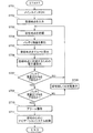
図7は図1に示される電動車いすのフロー図である。なお、ST××はステップ番号を示す(符号は図6参照)。
ST01:メインスイッチ87をONする。同時に夜間の場合は、前照灯21,21(図1参照)及び後部灯火器38のライト類のスイッチをONにする。
ST02:走行を開始するときに希望の位置を登録する。若しくは、予め登録してある位置を登録地点とする(以下、「登録地点」と記載する)。通常は自宅のある位置が登録地点である。
なお、登録地点は、走行を開始するときの希望の位置又は予め設定してある位置であるから、走行を開始するときに、最終的に到達を希望する地点(最終到達希望地点)を登録地点と考えればよい。
FIG. 7 is a flowchart of the electric wheelchair shown in FIG. Note that STxx indicates a step number (see FIG. 6 for the symbol).
ST01: The
ST02: A desired position is registered when traveling is started. Alternatively, a position registered in advance is set as a registered point (hereinafter referred to as “registered point”). Usually, the location where your home is is the registration point.
In addition, since the registration point is a desired position when starting traveling or a preset position, when starting traveling, a point where final arrival is desired (the final desired arrival point) is registered. I think that.
ST03:ナビゲーションシステム32により、現在の電動車いす10の位置(以下、「現在地点」と記載する)を把握する。
ST04:バッテリ残量検知手段135で、現在地点のバッテリ25の残量を算出する。
ST05:登録地点に到達するための経路(ルート)を算出する。
ST03: The
ST04: The remaining battery amount detection means 135 calculates the remaining amount of the
ST05: A route (route) for reaching the registered point is calculated.
ST06:経路情報に基づき、電力量算出手段136で登録地点に到達するための電力量を算出する。
ST07:到達可能性判定手段137で、現在のバッテリ25の残量と登録地点まで到達するための電力量を比較し、登録地点まで戻った場合に、バッテリ25の残量は20%を下回るかどうか判断する。YESの場合はST08に進む。NOの場合はST03に戻る。さらに遠方までの走行の継続が可能である。
ST06: Based on the route information, the power amount calculation means 136 calculates the power amount for reaching the registration point.
ST07: The reachability determination means 137 compares the current remaining amount of the
ST08:到達可能性判定手段137で、現在のバッテリ25の残量と登録地点まで到達するための電力量を比較し、登録地点まで戻った場合に、バッテリ25の残量は15%を下回るかどうか判断する。YESの場合はST10に進む。NOの場合はST09を経由してST03に戻る。さらに遠方までの走行の継続が可能である。
ST08: The reachability determination means 137 compares the current remaining amount of the
ST09:表示手段33に帰宅若しくは充電を促す表示をする。
ST10:表示手段33に付設したアラーム(不図示)で警告をする。なお、表示手段33に帰宅若しくは充電を促す表示は、この場合も継続されたままの状態にある。
ST09: The display means 33 is displayed to prompt the user to return home or charge.
ST10: A warning is given by an alarm (not shown) attached to the display means 33. Note that the display urging the
ST11:コントローラ134にてナビゲーションシステム32が自動で起動され、表示手段(誘導経路表示手段)33で登録地点(自宅)までの案内(通称「帰宅ナビ」)が開始される。なお、ナビゲーションボタン95(図5参照)でナビゲーションシステム32を解除し、登録地点(自宅)以外の目的地へ行くことは可能である。
ST11: The
図8は図1に示される電動車いすの経路情報算出の一例を示す説明図であり、図9は図1に示される電動車いすの電力量マップの一例を示すグラフである。
図8に示されたように、電力量算出手段136(図6参照)では、ナビゲーションシステム32に備えた地図情報116から、現在地点から登録地点(自宅)間のルートの路面斜度の変化点P1〜P8を見つけ、この路面斜度の変化点P1〜P8で現在地点から登録地点(自宅)間のルートを分割する。
FIG. 8 is an explanatory diagram showing an example of route information calculation of the electric wheelchair shown in FIG. 1, and FIG. 9 is a graph showing an example of an electric energy map of the electric wheelchair shown in FIG.
As shown in FIG. 8, the electric energy calculation means 136 (see FIG. 6) uses the
すなわち、現在地点から変化点P1までの分割区間をSa、変化点P1から変化点P2までの分割区間をSb、変化点P2から変化点P3までの分割区間をSc、変化点P3から変化点P4までの分割区間をSd、変化点P4から変化点P5までの分割区間をSe、変化点P5から変化点P6までの分割区間をSf、変化点P6から変化点P7までの分割区間をSg、変化点P7から変化点P8までの分割区間をSh、変化点P8から登録地点(自宅)までの分割区間をSjに区分する。 That is, Sa is a divided section from the current point to the change point P1, Sb is a divided section from the change point P1 to the change point P2, Sc is a divided section from the change point P2 to the change point P3, and is a change point P4 from the change point P3. Is divided into Sd, the divided section from the change point P4 to the change point P5 is Se, the divided section from the change point P5 to the change point P6 is Sf, the divided section from the change point P6 to the change point P7 is Sg, the change A divided section from the point P7 to the change point P8 is divided into Sh, and a divided section from the change point P8 to the registration point (home) is divided into Sj.
そして、電力量算出手段136では、図9に示される電力量マップ138を参照し、それぞれの分割区間Sa〜Sjにおいて、走行距離La〜Lj及び路面斜度(平均路面斜度)Ha〜Hjから電力量が算出され、分割区間Sa〜Sjの電力量が合算される。
Then, the electric energy calculation means 136 refers to the
一般的に、平地走行と路面斜度10度上り走行とではバッテリの電力消費量に約5倍の差があることが知られる。従って、電動車いす10の電力量(消費電力量)を予測する場合に路面斜度のファクタは必要不可欠のものと言える。
電力量算出手段136(図6参照)は、現在地点から登録地点までの走行距離La〜Lj情報と、現在地点から前記登録地点までの高低差情報(路面斜度Ha〜Hj情報)とに基づき電力量が算出されるので、バッテリ25の残量算出の精度を向上することができる。
In general, it is known that there is a difference of about 5 times in the power consumption of the battery between traveling on flat ground and traveling on an upward slope of 10 degrees. Therefore, it can be said that the road slope factor is indispensable when predicting the amount of electric power (power consumption) of the
The electric energy calculation means 136 (see FIG. 6) is based on the travel distances La to Lj information from the current location to the registered location, and the height difference information (road surface slope Ha to Hj information) from the current location to the registered location. Since the amount of electric power is calculated, the accuracy of calculating the remaining amount of the
図9に示された電力量マップ138は、電力量(消費電力量)と路面斜度との関係を示すマップであり、路面斜度が大きくなれば消費される電力量は増加し、路面斜度がマイナス(下り勾配)では、電力量の回生が行われる。
The
すなわち、図1に示される電動車いす10では、バッテリ25から電動モータ26に電力供給され、この電動モータ26で車輪28,28が回転駆動され、走行を開始するときに登録する希望の位置又は予め設定してある位置を登録地点、走行中の現在の位置を現在地点とするときに、現在地点から登録地点に到達するための情報が提供される。
That is, in the
図6に示されたように、情報提供手段130に、バッテリの残量を検知するバッテリ残量検知手段135と、現在地点から登録地点までの経路情報に基づき、現在地点から登録地点まで到達するために必要な所要電力量を算出する電力量算出手段136と、これらのバッテリ残量検知手段135及び電力量算出手段136の情報に基づき、現在地点から登録地点まで到達できるか否かを判定する到達可能性判定手段137とを備えたので、あとどれくらい走行できるかなどの走行可能距離を知ることができ、バッテリ25の残量に余裕がある場合にはさらに遠方まで走行することができる。
As shown in FIG. 6, the
また、情報提供手段130に、到達可能性判定手段137の判定結果に応じて、例えば、バッテリ25の残量が乏しいと判定された場合に、乗員12に対し登録地点へ向かうように促すようにしたので、登録地点(自宅)へ到達(帰宅)できるか否かを気にせず走行することができる。この結果、電動車いす10の乗員(使用者)12の帰宅できるかという走行時の不安を取去ることができ、乗員の利便性の向上を図ることができる。
In addition, according to the determination result of the
図10(a)〜(c)は図1に示される電動車いすの表示手段の帰宅誘導表示の一例を示す説明図である。
図5に示された表示手段33は、登録地点(自宅)までの経路を誘導する誘導経路表示手段であり、以下の画面が表示される。(a)において、「次の角で左に曲がってください」と表示されたときは左に曲がり、(b)において、「次の角で右に曲がってください」と表示されたときは右に曲がり、(c)において、「次の交差点はそのまま直進です」と表示されたときは直進すれば、道に迷うことなく帰宅することができる。
10 (a) to 10 (c) are explanatory views showing an example of the return guidance display of the display means of the electric wheelchair shown in FIG.
The display means 33 shown in FIG. 5 is a guidance route display means for guiding a route to a registration point (home), and the following screen is displayed. In (a), turn left when "Turn left at the next corner" is displayed, and to the right when (Turn right at the next corner) is displayed in (b) Turn and go straight when you see “Next intersection is straight ahead” in (c), you can go home without getting lost.
情報提供手段130は、現在地点から登録地点までの誘導経路の表示を行う表示手段(誘導経路表示手段)33を備えたので、乗員(使用者)12は誘導経路の表示に従って走行すればよく、確実に登録地点(自宅)に到達(戻る)することができる。
Since the
尚、本発明に係る電動車いすは、図8及び図9に示すように、電力量算出手段136では、路面斜度の変化点P1〜P8で現在地点から登録地点(自宅)間のルートを分割して電力量を算出したが、これに限るものではない。一例として、現在地点から登録地点(自宅)間のルートをn分割する方法でもよく、nの値は全体距離により変化してもよい(例えば、ある区間〜3kmはn=20、3km〜別区間はn=40など)。また、現在地点から登録地点(自宅)間のルートを規定値間隔に分割するものであってもよい(例えば、100m、500m毎等に分割し、分割する距離は全体距離に応じて変化してもよい)。 In the electric wheelchair according to the present invention, as shown in FIGS. 8 and 9, the electric energy calculation means 136 divides the route from the current point to the registered point (home) at the change points P1 to P8 of the road surface inclination. Thus, the amount of power is calculated, but the present invention is not limited to this. As an example, a method of dividing the route from the current point to the registered point (home) by n may be used, and the value of n may vary depending on the total distance (for example, a certain section to 3 km is n = 20, 3 km to another section) N = 40 etc.). Further, the route from the current point to the registered point (home) may be divided into specified value intervals (for example, divided into every 100 m, 500 m, etc., and the divided distance varies depending on the total distance. Also good).
本発明に係る電動車いすは、図7に示すように、バッテリ25の残量の残量によって、表示手段33に帰宅若しくは充電を促す表示をしたり、表示手段33に付設したアラームで警告したが、これは一例のアラート(注意手段)であり、アラートの手法は任意に設定してもよい。また、複数のアラートを、適宜、組合わせたものであってもよい。
In the electric wheelchair according to the present invention, as shown in FIG. 7, depending on the remaining amount of the
本発明に係る電動車いすは、高齢者等が利用する歩行補助具に好適である。 The electric wheelchair according to the present invention is suitable for walking aids used by elderly people and the like.
10…電動車いす、25…バッテリ、26…電動モータ、33…表示手段(誘導経路表示手段)、130…情報提供手段、135…バッテリ残量検知手段、136…電力量算出手段、137…到達可能性判断手段。
DESCRIPTION OF
Claims (2)
前記情報提供手段は、前記バッテリの残量を検知するバッテリ残量検知手段と、前記現在地点から前記登録地点までの経路情報に基づき、前記現在地点から前記登録地点まで到達するために必要な所要電力量を算出する電力量算出手段と、これらのバッテリ残量検知手段及び電力量算出手段の情報に基づき、前記現在地点から前記登録地点まで到達できるか否かを判定する到達可能性判定手段とを備え、
この到達可能性判定手段の判定結果に応じて乗員に対し前記登録地点へ向かうように促すものであり、
前記情報提供手段は、位置検出機能を有するナビゲーションシステムと、前記現在地点から前記登録地点までの誘導経路の表示を行う誘導経路表示手段と、を備え、
前記到達可能性判定手段で、現在の前記バッテリの残量と前記登録地点まで到達するための電力量を比較し、前記登録地点まで到達した場合に、前記バッテリの残量が乏しくなると判断された場合には、前記ナビゲーションシステムを自動で起動し、最終的に到達を希望する最終到達希望地点としての登録地点までの案内を、前記誘導経路表示手段で開始することを特徴とする電動車いす。 The electric motor supplied with power from the battery, the wheels that are driven to rotate by this electric motor, the desired position to be registered when starting traveling or a preset position as the registration point, and the current position during traveling An electric wheelchair provided with information providing means for providing information for reaching the registered point from the current point,
The information providing means includes a battery remaining amount detecting means for detecting the remaining amount of the battery, and necessary information necessary for reaching from the current location to the registered location based on route information from the current location to the registered location. A power amount calculating means for calculating a power amount, and a reachability determining means for determining whether or not the current location can be reached from the current location based on information of the remaining battery level detecting means and the power amount calculating means; With
Depending on the determination result of the reachability determination means, the passenger is urged to go to the registration point,
The information providing means includes a navigation system having a position detection function, and guidance route display means for displaying a guidance route from the current location to the registered location,
The reachability determination means compares the current remaining amount of the battery with the amount of power to reach the registration point, and when reaching the registration point, it is determined that the remaining amount of the battery becomes low. in this case, the navigation system starts automatically, guidance finally reach to the registered location as the final arrival desired point desired, electric wheelchair, characterized in that to start with the guidance path display means.
Priority Applications (5)
| Application Number | Priority Date | Filing Date | Title |
|---|---|---|---|
| JP2007260683A JP5113473B2 (en) | 2007-10-04 | 2007-10-04 | Electric wheelchair |
| EP08017227A EP2045117B1 (en) | 2007-10-04 | 2008-09-30 | Small-sized motorized vehicle |
| ES08017227T ES2394879T3 (en) | 2007-10-04 | 2008-09-30 | Small motorized vehicle |
| AU2008229769A AU2008229769B9 (en) | 2007-10-04 | 2008-10-02 | Small-sized motorized vehicle |
| CN2008101659928A CN101401759B (en) | 2007-10-04 | 2008-10-06 | Small-sized motorized vehicle |
Applications Claiming Priority (1)
| Application Number | Priority Date | Filing Date | Title |
|---|---|---|---|
| JP2007260683A JP5113473B2 (en) | 2007-10-04 | 2007-10-04 | Electric wheelchair |
Publications (2)
| Publication Number | Publication Date |
|---|---|
| JP2009089756A JP2009089756A (en) | 2009-04-30 |
| JP5113473B2 true JP5113473B2 (en) | 2013-01-09 |
Family
ID=40262073
Family Applications (1)
| Application Number | Title | Priority Date | Filing Date |
|---|---|---|---|
| JP2007260683A Expired - Fee Related JP5113473B2 (en) | 2007-10-04 | 2007-10-04 | Electric wheelchair |
Country Status (5)
| Country | Link |
|---|---|
| EP (1) | EP2045117B1 (en) |
| JP (1) | JP5113473B2 (en) |
| CN (1) | CN101401759B (en) |
| AU (1) | AU2008229769B9 (en) |
| ES (1) | ES2394879T3 (en) |
Families Citing this family (16)
| Publication number | Priority date | Publication date | Assignee | Title |
|---|---|---|---|---|
| JP5141705B2 (en) | 2010-03-19 | 2013-02-13 | アイシン・エィ・ダブリュ株式会社 | Driving support apparatus, method and program |
| JP5443241B2 (en) * | 2010-03-30 | 2014-03-19 | 株式会社東芝 | Battery control device for electric vehicle |
| JP5771902B2 (en) * | 2010-04-14 | 2015-09-02 | ソニー株式会社 | Route guidance device, route guidance method and computer program |
| JP5742117B2 (en) * | 2010-06-03 | 2015-07-01 | 日産自動車株式会社 | Information presentation device for vehicle |
| CN101893671A (en) * | 2010-06-28 | 2010-11-24 | 宁夏电力公司银川供电局 | Method for detecting motor-unconnected fault of electric wheelchair based on DSP |
| KR20120036563A (en) * | 2010-10-08 | 2012-04-18 | 현대자동차주식회사 | Navigation service device for electric vehicles and service method thereof |
| JP2012228165A (en) | 2011-04-07 | 2012-11-15 | Honda Motor Co Ltd | Electric vehicle charge control system |
| JP5722686B2 (en) * | 2011-04-12 | 2015-05-27 | クラリオン株式会社 | Driving support apparatus and vehicle having the apparatus |
| US20130024112A1 (en) * | 2011-07-18 | 2013-01-24 | GM Global Technology Operations LLC | System and method for generating recommended driving routes for an electric vehicle |
| JP5704372B2 (en) * | 2011-08-12 | 2015-04-22 | トヨタ自動車株式会社 | Charging information providing device |
| CN103112360B (en) * | 2013-02-27 | 2015-12-09 | 浙江吉利汽车研究院有限公司杭州分公司 | A kind of driving ancillary system of electronlmobil and method |
| JP6025146B2 (en) * | 2013-05-23 | 2016-11-16 | カルソニックカンセイ株式会社 | Electric vehicle cruising distance notification device |
| JP5879325B2 (en) * | 2013-10-28 | 2016-03-08 | 本田技研工業株式会社 | External power supply device and electric vehicle |
| JP2020063940A (en) * | 2018-10-16 | 2020-04-23 | トヨタ自動車株式会社 | Mobile |
| CN109966064B (en) * | 2019-04-04 | 2021-02-19 | 北京理工大学 | Wheelchair and control method integrating brain control and automatic driving with detection device |
| DE102024201433A1 (en) * | 2024-02-16 | 2025-08-21 | Volkswagen Aktiengesellschaft | Method and device for outputting feedback about a relative position of a mobility aid with respect to a target position |
Family Cites Families (9)
| Publication number | Priority date | Publication date | Assignee | Title |
|---|---|---|---|---|
| JPH04166779A (en) * | 1990-10-30 | 1992-06-12 | Fuji Kiko Co Ltd | Apparatus for indicating consumption of battery |
| JP3336777B2 (en) * | 1994-10-25 | 2002-10-21 | 株式会社エクォス・リサーチ | Hybrid vehicle and hybrid vehicle control method |
| JP3264123B2 (en) * | 1995-03-06 | 2002-03-11 | 三菱自動車工業株式会社 | Navigation system for hybrid electric vehicles |
| JP2000279451A (en) * | 1999-03-31 | 2000-10-10 | Matsushita Electric Works Ltd | Motor-driven wheelchair provided with movable distance detecting means |
| JP3548725B2 (en) * | 2001-03-07 | 2004-07-28 | 株式会社日立製作所 | Outing support system and moving object |
| JP2003010257A (en) * | 2001-07-04 | 2003-01-14 | Matsushita Electric Ind Co Ltd | Route information collection wheelchair |
| JP2003345436A (en) * | 2002-05-30 | 2003-12-05 | Fujitsu Ten Ltd | Guidance device, golf course guidance device, and amusement facility guidance device |
| JP2004266898A (en) * | 2003-02-28 | 2004-09-24 | Asti Corp | Vehicle control device |
| JP2005152189A (en) * | 2003-11-25 | 2005-06-16 | Asti Corp | Vehicle control device |
-
2007
- 2007-10-04 JP JP2007260683A patent/JP5113473B2/en not_active Expired - Fee Related
-
2008
- 2008-09-30 EP EP08017227A patent/EP2045117B1/en not_active Not-in-force
- 2008-09-30 ES ES08017227T patent/ES2394879T3/en active Active
- 2008-10-02 AU AU2008229769A patent/AU2008229769B9/en not_active Ceased
- 2008-10-06 CN CN2008101659928A patent/CN101401759B/en not_active Expired - Fee Related
Also Published As
| Publication number | Publication date |
|---|---|
| CN101401759B (en) | 2011-12-14 |
| EP2045117A3 (en) | 2009-11-25 |
| ES2394879T3 (en) | 2013-02-06 |
| CN101401759A (en) | 2009-04-08 |
| AU2008229769B9 (en) | 2013-07-11 |
| AU2008229769A1 (en) | 2009-04-23 |
| AU2008229769B2 (en) | 2013-06-27 |
| EP2045117B1 (en) | 2012-11-14 |
| JP2009089756A (en) | 2009-04-30 |
| EP2045117A2 (en) | 2009-04-08 |
Similar Documents
| Publication | Publication Date | Title |
|---|---|---|
| JP5113473B2 (en) | Electric wheelchair | |
| JP5113474B2 (en) | Electric wheelchair | |
| ES2704724T3 (en) | Straddle-type vehicle with approach notification device | |
| JP5046842B2 (en) | Small electric vehicle | |
| JP5046843B2 (en) | Small electric vehicle | |
| JP2026009355A (en) | Self-propelled vehicles | |
| CN102556063A (en) | Intelligent electric mobility scooter | |
| JP6848343B2 (en) | Electric vehicle | |
| JP2013106896A (en) | Small electric vehicle | |
| JP2024114261A (en) | Micromobility and its control method | |
| JP2007106222A (en) | Two-wheeler with auxiliary wheel | |
| JP2018134966A (en) | Display unit for power-assisted bicycle and power-assisted bicycle | |
| JP2024163239A (en) | Electric drive assist device with driver on board | |
| JP2023011193A (en) | Compact motor-driven vehicle | |
| KR101734573B1 (en) | Steering control system for mobile using movement of upper body |
Legal Events
| Date | Code | Title | Description |
|---|---|---|---|
| A621 | Written request for application examination |
Free format text: JAPANESE INTERMEDIATE CODE: A621 Effective date: 20091126 |
|
| A131 | Notification of reasons for refusal |
Free format text: JAPANESE INTERMEDIATE CODE: A131 Effective date: 20110712 |
|
| A977 | Report on retrieval |
Free format text: JAPANESE INTERMEDIATE CODE: A971007 Effective date: 20110714 |
|
| A521 | Request for written amendment filed |
Free format text: JAPANESE INTERMEDIATE CODE: A523 Effective date: 20110901 |
|
| A131 | Notification of reasons for refusal |
Free format text: JAPANESE INTERMEDIATE CODE: A131 Effective date: 20120306 |
|
| A521 | Request for written amendment filed |
Free format text: JAPANESE INTERMEDIATE CODE: A523 Effective date: 20120418 |
|
| TRDD | Decision of grant or rejection written | ||
| A01 | Written decision to grant a patent or to grant a registration (utility model) |
Free format text: JAPANESE INTERMEDIATE CODE: A01 Effective date: 20121009 |
|
| A01 | Written decision to grant a patent or to grant a registration (utility model) |
Free format text: JAPANESE INTERMEDIATE CODE: A01 |
|
| A61 | First payment of annual fees (during grant procedure) |
Free format text: JAPANESE INTERMEDIATE CODE: A61 Effective date: 20121012 |
|
| FPAY | Renewal fee payment (event date is renewal date of database) |
Free format text: PAYMENT UNTIL: 20151019 Year of fee payment: 3 |
|
| R150 | Certificate of patent or registration of utility model |
Ref document number: 5113473 Country of ref document: JP Free format text: JAPANESE INTERMEDIATE CODE: R150 Free format text: JAPANESE INTERMEDIATE CODE: R150 |
|
| R250 | Receipt of annual fees |
Free format text: JAPANESE INTERMEDIATE CODE: R250 |
|
| LAPS | Cancellation because of no payment of annual fees |