JP5111990B2 - Locking device and locking / unlocking method - Google Patents
Locking device and locking / unlocking method Download PDFInfo
- Publication number
- JP5111990B2 JP5111990B2 JP2007256021A JP2007256021A JP5111990B2 JP 5111990 B2 JP5111990 B2 JP 5111990B2 JP 2007256021 A JP2007256021 A JP 2007256021A JP 2007256021 A JP2007256021 A JP 2007256021A JP 5111990 B2 JP5111990 B2 JP 5111990B2
- Authority
- JP
- Japan
- Prior art keywords
- locking
- unlocking
- state
- doorway
- hole
- Prior art date
- Legal status (The legal status is an assumption and is not a legal conclusion. Google has not performed a legal analysis and makes no representation as to the accuracy of the status listed.)
- Active
Links
Images


Landscapes
- Lock And Its Accessories (AREA)
Description
本発明は、出入口扉を施解錠する錠前装置および施解錠方法に関するものであり、特に、二つの施解錠部を備えた錠前装置および施解錠方法に関する。 The present invention relates to a locking device and a locking / unlocking method for locking / unlocking an entrance door, and particularly to a locking device and a locking / unlocking method including two locking / unlocking portions.
近年、不正な侵入を防止する目的で、一つの出入口扉に主錠と補助錠の二つの施解錠部を備えた錠前装置を設置する所謂ワンドアツーロックを実施して、防犯性の向上を図る試みがなされている。すなわち、ワンドアツーロックを実施することで期待できる効果としては、主錠と補助錠とを設置することにより、各種非破壊不正解錠手段(ピッキング、サムターン回し等)における作業の手間・所要時間を2倍程度にすること、出入口扉や錠前装置の破壊を伴う不正開放手段(こじ開け、錠破り等)を物理的に困難にすること、及び、補助錠を設置することにより、不正解錠が困難であることに加えて、居住者の防犯意識が高いことを不正侵入者に感じさせて犯意を失わせるとともに、犯行に至らなくさせることが挙げられる。 In recent years, for the purpose of preventing unauthorized intrusion, an attempt to improve crime prevention by implementing so-called one-door-to-lock that installs a lock device equipped with two locking and unlocking parts of a main lock and an auxiliary lock on one doorway Has been made. In other words, the effect that can be expected by carrying out one-door-to-lock is that by installing a main lock and an auxiliary lock, it is possible to reduce the labor and time required for work in various non-destructive illegal unlocking means (picking, thumb turn, etc.). Unauthorized unlocking is difficult by making it about double, making unauthorized opening means (breaking, breaking the lock, etc.) illegally involving the entrance door and lock device, and installing an auxiliary lock. In addition to the above, it is possible to make an intruder feel that the resident's security consciousness is high, thereby losing the criminal intention and preventing the crime from being committed.
従って、従来から、一つの出入口扉に主錠と補助錠の二つの施解錠部を備えた錠前装置が一般的に利用されている。例えば、室外側から施錠するときは一方のシリンダ錠を施錠すれば他のシリンダ錠も自動的に施錠できるが、解錠するときには夫々別個に解錠するようにした施錠装置が開示されている(例えば、特許文献1参照)。また、二つの電気錠のうち一方の電気錠を施錠した場合には、これと連動して他方の電気錠が施錠されるが、一方の電気錠を解錠した場合には、他方の電気錠はこの操作と連動せず施錠状態を維持する電気錠装置が開示されている(例えば、特許文献2参照)。 Therefore, conventionally, a lock device having two locking / unlocking portions of a main lock and an auxiliary lock on one doorway is generally used. For example, when locking from the outdoor side, if one cylinder lock is locked, the other cylinder lock can be automatically locked, but when unlocking, a locking device is disclosed in which each is unlocked separately ( For example, see Patent Document 1). Also, when one of the two electric locks is locked, the other electric lock is locked in conjunction with this, but when one of the electric locks is unlocked, the other electric lock is locked. Discloses an electric lock device that maintains a locked state without interlocking with this operation (see, for example, Patent Document 2).
しかしながら、従来技術のように、出入口扉に二つの施解錠部を備えた錠前装置を設置した場合、不正侵入者による錠前装置の解錠が困難となるが、正規の利用者が入退館する際にも、二つの施解錠部それぞれに対する施解錠操作が必要となる。また、上記特許文献1および特許文献2の技術では、出入口扉の施錠を行う場合は一回の施錠操作で二つの施解錠部を施錠することが可能となるが、出入口扉の解錠を行う際には、二つの施解錠部を備えた錠前装置を解錠するための二回の解錠操作が必要になる。このため、出入口扉に単独の施解錠部を備えた錠前装置を設置している場合と比較すると解錠操作が二段階となるため、正規の利用者による操作が煩雑となり利便性が低下するという問題があった。
However, when a lock device having two locking / unlocking portions is installed at the entrance door as in the prior art, it becomes difficult for an unauthorized intruder to unlock the lock device, but a regular user enters and leaves the building. In some cases, a locking / unlocking operation for each of the two locking / unlocking portions is required. Moreover, in the technique of the said patent document 1 and the
本発明は、上記に鑑みてなされたものであって、第1施解錠部と第2施解錠部とを連結することで、正規の利用者には一回の施解錠操作で出入口扉の施解錠を可能にして煩雑な施解錠操作を強要せず利便性を向上させるとともに、不正侵入者には解錠操作を困難にし、かつ出入口扉の不正開放に対する物理的耐性を高めることで防犯性を向上できる錠前装置および施解錠方法を提供することを目的とする。 The present invention has been made in view of the above, and by connecting the first locking / unlocking portion and the second locking / unlocking portion, an authorized user can unlock and unlock the entrance door with a single locking / unlocking operation. It is possible to lock and improve the convenience without complicating complicated unlocking and unlocking operations, making it difficult for unauthorized intruders to unlock, and increasing the physical resistance against unauthorized opening of the entrance door to increase security An object of the present invention is to provide a lock device and a locking / unlocking method that can be improved.
上述した課題を解決し、目的を達成するために、請求項1にかかる発明は、出入口扉に設置され、前記出入口扉を開放不可能な施錠状態、前記出入口扉を開放可能な解錠状態、または前記解錠状態に移行可能な解錠可能状態にする錠前装置において、前記錠前装置に対向して出入口の壁面に設けられた第1孔部に挿脱可能であって、前記第1孔部に挿入した状態で保持されることによって前記出入口扉を前記施錠状態にし、前記出入口扉の前記第1孔部に対して移動可能な状態にされることによって前記出入口扉を前記解錠可能状態にする第1施解錠部と、前記錠前装置に対向して出入口の壁面に設けられた第2孔部に挿脱可能であって、前記第2孔部に挿入した状態で保持されることによって前記出入口扉を前記施錠状態にし、前記出入口扉の前記第2孔部に対して移動可能な状態にされることによって前記出入口扉を前記解錠可能状態にする第2施解錠部と、前記第1施解錠部と前記第2施解錠部とを連結する連結部材と、利用者から第1操作力を受付け、前記第1操作力を前記第1施解錠部に伝達することで前記第1施解錠部を移動させる開閉操作部と、所定条件の場合、前記第1操作力を前記第1施解錠部に伝達することで、前記第1施解錠部を前記第1孔部に移動させるとともに、前記第2施解錠部を第1施解錠部の移動に連動して前記第2孔部に移動させ、前記出入口扉を前記解錠可能状態から前記解錠状態にする伝達部と、を備え、前記伝達部は、前記開閉操作部に連結されており、前記第1施解錠部に係合することにより前記出入口扉を前記施錠状態または前記解錠可能状態とし、前記第1施解錠部に係合し、かつ前記第1操作力を前記第1施解錠部に伝達することで前記第1施解錠部を移動させ、前記第1施解錠部との係合を解除して前記第1操作力の前記第1施解錠部への伝達を不能にすることで前記第1施解錠部を移動不能にする係合部材を備えること、を特徴とする。 In order to solve the above-described problems and achieve the object, the invention according to claim 1 is installed in an entrance door, the locked state in which the entrance door cannot be opened, the unlocked state in which the entrance door can be opened, Alternatively, in the unlocking device that is in an unlockable state that can be shifted to the unlocked state, the first hole portion can be inserted into and removed from a first hole portion provided in a wall surface of the doorway so as to face the locking device. The entrance door is set in the locked state by being held in the state inserted into the doorway, and the entrance door is brought into the unlockable state by being made movable relative to the first hole of the entrance door. The first locking / unlocking portion and the second hole portion provided in the wall surface of the doorway facing the lock device are detachable and are held in the state inserted into the second hole portion. The doorway is in the locked state, and the doorway A second locking / unlocking portion for bringing the doorway into the unlockable state by being movable with respect to the second hole portion, the first locking / unlocking portion, and the second locking / unlocking portion, A connecting member that connects the first and second locking members, an opening / closing operation unit that receives the first operating force from the user and transmits the first operating force to the first locking / unlocking unit, and a predetermined condition In this case, by transmitting the first operating force to the first locking / unlocking portion, the first locking / unlocking portion is moved to the first hole portion, and the second locking / unlocking portion is moved to the first locking / unlocking portion. A transmission unit that moves the doorway to the unlocked state from the unlockable state to the unlocking state, and the transmission unit is connected to the opening / closing operation unit. And engaging the first locking / unlocking portion to lock the doorway in the locked state or in the unlocked state. The first locking / unlocking part is moved by engaging the first locking / unlocking part and transmitting the first operating force to the first locking / unlocking part, An engagement member that disengages the first operating force and disables transmission of the first operating force to the first locking / unlocking portion, thereby disabling the first locking / unlocking portion. .
また、請求項2にかかる発明は、請求項1に記載の錠前装置において、前記第2施解錠部は、複数設けられ、前記連結部材は、前記第1施解錠部と複数の第2施解錠部とを連結し、前記伝達部は、所定条件の場合、前記第1操作力を前記第1施解錠部に伝達することで、前記第1施解錠部を前記第1孔部に移動させるとともに、複数の第2施解錠部を第1施解錠部の移動に連動して前記第2孔部に移動させ、前記出入口扉を前記解錠可能状態から前記解錠状態にすることを特徴とする。 According to a second aspect of the present invention, in the lock device according to the first aspect, a plurality of the second locking / unlocking portions are provided, and the connecting member includes the first locking / unlocking portion and the plurality of second locking / unlocking portions. When the predetermined condition is satisfied, the transmission unit transmits the first operating force to the first locking / unlocking unit to move the first locking / unlocking unit to the first hole. The plurality of second locking / unlocking portions are moved to the second hole portion in conjunction with the movement of the first locking / unlocking portion, and the doorway is changed from the unlockable state to the unlocked state. .
また、請求項3にかかる発明は、請求項1または2に記載の錠前装置において、前記錠前装置は、前記出入口扉が設置された監視領域における異常事態の発生の有無を監視する警備装置と接続され、利用者から第2操作力を受付ける施解錠操作部と、前記出入口扉付近に設けられ、前記警備装置によって前記監視領域の異常が検知された場合に異常検知情報を通報する警備状態、または前記警備装置によって前記監視領域の異常が検知された場合に前記異常検知情報を通報しない警備解除状態の設定を受付ける操作部と、をさらに備え、前記係合部材は、前記所定条件として、前記施解錠操作部により前記第2操作力を受付け、かつ前記操作部により前記警備解除状態の設定を受付けた場合に、前記第1施解錠部に係合することを特徴とする。 According to a third aspect of the present invention, in the lock device according to the first or second aspect , the lock device is connected to a security device that monitors the occurrence of an abnormal situation in the monitoring area where the doorway is installed. A locking / unlocking operation unit that receives a second operating force from a user and a security state that is provided in the vicinity of the entrance door and that reports abnormality detection information when an abnormality of the monitoring area is detected by the security device, or An operation unit that accepts a setting of a security release state that does not report the abnormality detection information when an abnormality of the monitoring area is detected by the security device, and the engagement member is configured to perform the application as the predetermined condition. When the second operation force is received by the lock operation unit and the setting of the security release state is received by the operation unit, the lock operation unit is engaged with the first locking / unlocking unit.
また、請求項4にかかる発明は、請求項3に記載の錠前装置において、稼働可能な鉄心を有するソレノイドをさらに備え、前記伝達部は、前記第1施解錠部の近傍である一方の端部に第1突起部が形成され、前記第2操作力によって押圧されることで第1方向へ移動し、前記第1突起部が前記第1施解錠部の内部方向へ移動することで前記係合部材への押圧を解除し、第3操作力によって押圧されることで第1方向と逆方向である第2方向へ移動し、前記第1突起部が前記第1施解錠部の外部方向へ移動することで前記係合部材を押圧する可動部材と、前記ソレノイドに対する通電を制御し、前記操作部により前記警備状態から前記警備解除状態の設定を受付けた場合、前記ソレノイドを非通電にし、前記操作部により前記警備解除状態から前記警備状態の設定を受付けた場合、前記ソレノイドを通電する制御部と、一方の端部近傍で前記鉄心に連結され、他方の端部近傍に第2突起部が形成されており、前記ソレノイドへの非通電に連動して前記第2突起部が前記第1施解錠部の内部方向へ移動することで前記係合部材への押圧を解除し、前記ソレノイドへの通電に連動して前記第2突起部が前記第1施解錠部の外部方向へ移動することで前記係合部材を押圧する押圧部材と、をさらに備え、前記係合部材は、前記第1突起部が前記第2操作力により前記第1施解錠部の内部方向へ移動し、かつ前記第2突起部が前記ソレノイドの非通電により第1施解錠部の内部方向へ移動した場合に、前記第1施解錠部に係合することを特徴とする。
The invention according to
また、請求項5にかかる発明は、請求項4に記載の錠前装置において、前記係合部材を、前記第1施解錠部側の方向に付勢する弾性部材をさらに備え、前記係合部材は、前記可動部材および前記押圧部材からの押圧が解除された場合、前記弾性部材からの付勢力によって前記第1施解錠部に係合し、前記可動部材および前記押圧部材は、前記弾性部材からの付勢力に対抗して、前記係合部材を押圧し、前記係合部材と前記第1施解錠部との係合を解除することを特徴とする。
The invention according to claim 5 is the lock device according to
また、請求項6にかかる発明は、請求項1〜5のいずれか一つに記載の錠前装置において、施解錠機能を有さず、前記錠前装置に前記第2施解錠部が設置されており、かつ前記第2施解錠部を操作することを連想させる模造施解錠操作部をさらに備えることを特徴とする。 The invention according to claim 6 is the lock device according to any one of claims 1 to 5 , wherein the lock device does not have a locking / unlocking function, and the second locking / unlocking portion is installed in the lock device. And an imitation locking / unlocking operation unit reminiscent of operating the second locking / unlocking unit.
また、請求項7にかかる発明は、出入口扉に設置され、前記出入口扉を開放不可能な施錠状態、前記出入口扉を開放可能な解錠状態、または前記解錠状態に移行可能な解錠可能状態にする錠前装置で実行される施解錠方法において、前記錠前装置に対向して出入口の壁面に設けられた第1孔部に挿脱可能な第1施解錠部により、前記第1孔部に挿入した状態で保持されることによって前記出入口扉を前記施錠状態にし、前記出入口扉の前記第1孔部に対して移動可能な状態にされることによって前記出入口扉を前記解錠可能状態にする第1施解錠工程と、前記錠前装置に対向して出入口の壁面に設けられた第2孔部に挿脱可能な第2施解錠部により、前記第2孔部に挿入した状態で保持されることによって前記出入口扉を前記施錠状態にし、前記出入口扉の前記第2孔部に対して移動可能な状態にされることによって前記出入口扉を前記解錠可能状態にする第2施解錠工程と、開閉操作部により、利用者から第1操作力を受付け、前記第1操作力を前記第1施解錠部に伝達することで前記第1施解錠部を移動させる開閉操作工程と、所定条件の場合、伝達部により前記第1操作力を前記第1施解錠部に伝達することで、前記第1施解錠部を前記第1孔部に移動させるとともに、連結部材により前記第1施解錠部と連結する前記第2施解錠部を第1施解錠部の移動に連動して前記第2孔部に移動させ、前記出入口扉を前記解錠可能状態から前記解錠状態にする伝達工程と、を含み、前記伝達工程は、前記開閉操作部に連結された前記伝達部により、前記第1施解錠部に係合することにより前記出入口扉を前記施錠状態または前記解錠可能状態とし、前記伝達部に備えられた係合部材により、前記第1施解錠部に係合し、かつ前記第1操作力を前記第1施解錠部に伝達することで前記第1施解錠部を移動させ、前記第1施解錠部との係合を解除して前記第1操作力の前記第1施解錠部への伝達を不能にすることで前記第1施解錠部を移動不能にすることを特徴とする。
また、請求項8にかかる発明は、出入口扉に設置され、前記出入口扉を開放不可能な施錠状態、前記出入口扉を開放可能な解錠状態、または前記解錠状態に移行可能な解錠可能状態にする錠前装置において、前記錠前装置に対向して出入口の壁面に設けられた第1孔部に挿脱可能であって、前記第1孔部に挿入した状態で保持されることによって前記出入口扉を前記施錠状態にし、前記出入口扉の前記第1孔部に対して移動可能な状態にされることによって前記出入口扉を前記解錠可能状態にする第1施解錠部と、前記錠前装置に対向して出入口の壁面に設けられた第2孔部に挿脱可能であって、前記第2孔部に挿入した状態で保持されることによって前記出入口扉を前記施錠状態にし、前記出入口扉の前記第2孔部に対して移動可能な状態にされることによって前記出入口扉を前記解錠可能状態にする第2施解錠部と、前記第1施解錠部と前記第2施解錠部とを連結する連結部材と、利用者から第1操作力を受付け、前記第1操作力を前記第1施解錠部に伝達することで前記第1施解錠部を移動させる開閉操作部と、所定条件の場合、前記第1操作力を前記第1施解錠部に伝達することで、前記第1施解錠部を前記第1孔部に移動させるとともに、前記第2施解錠部を第1施解錠部の移動に連動して前記第2孔部に移動させ、前記出入口扉を前記解錠可能状態から前記解錠状態にする伝達部と、を備え、前記第2施解錠部は、複数設けられ、前記連結部材は、前記第1施解錠部と複数の第2施解錠部とを連結し、前記伝達部は、所定条件の場合、前記第1操作力を前記第1施解錠部に伝達することで、前記第1施解錠部を前記第1孔部に移動させるとともに、複数の第2施解錠部を第1施解錠部の移動に連動して前記第2孔部に移動させ、前記出入口扉を前記解錠可能状態から前記解錠状態にすることを特徴とする。
また、請求項9にかかる発明は、出入口扉に設置され、前記出入口扉を開放不可能な施錠状態、前記出入口扉を開放可能な解錠状態、または前記解錠状態に移行可能な解錠可能状態にする錠前装置で実行される施解錠方法において、前記錠前装置に対向して出入口の壁面に設けられた第1孔部に挿脱可能な第1施解錠部により、前記第1孔部に挿入した状態で保持されることによって前記出入口扉を前記施錠状態にし、前記出入口扉の前記第1孔部に対して移動可能な状態にされることによって前記出入口扉を前記解錠可能状態にする第1施解錠工程と、前記錠前装置に対向して出入口の壁面に設けられた第2孔部に挿脱可能な第2施解錠部により、前記第2孔部に挿入した状態で保持されることによって前記出入口扉を前記施錠状態にし、前記出入口扉の前記第2孔部に対して移動可能な状態にされることによって前記出入口扉を前記解錠可能状態にする第2施解錠工程と、開閉操作部により、利用者から第1操作力を受付け、前記第1操作力を前記第1施解錠部に伝達することで前記第1施解錠部を移動させる開閉操作工程と、所定条件の場合、伝達部により前記第1操作力を前記第1施解錠部に伝達することで、前記第1施解錠部を前記第1孔部に移動させるとともに、連結部材により前記第1施解錠部と連結する前記第2施解錠部を第1施解錠部の移動に連動して前記第2孔部に移動させ、前記出入口扉を前記解錠可能状態から前記解錠状態にする伝達工程と、を含み、前記第2施解錠部は、複数設けられ、前記連結部材は、前記第1施解錠部と複数の第2施解錠部とを連結し、前記伝達工程は、所定条件の場合、前記伝達部により前記第1操作力を前記第1施解錠部に伝達することで、前記第1施解錠部を前記第1孔部に移動させるとともに、前記連結部材により前記第1施解錠部に連結する複数の第2施解錠部を第1施解錠部の移動に連動して前記第2孔部に移動させ、前記出入口扉を前記解錠可能状態から前記解錠状態にすることを特徴とする。
Further, the invention according to claim 7 is installed in the doorway and can be unlocked in a locked state in which the doorway cannot be opened, in an unlocked state in which the doorway can be opened, or in the unlocked state. In the locking / unlocking method executed by the lock device to be brought into a state, the first hole / unlocking portion can be inserted into and removed from the first hole portion provided in the wall surface of the entrance / exit by facing the lock device. The doorway door is brought into the locked state by being held in the inserted state, and the doorway door is brought into the unlockable state by being made movable relative to the first hole of the doorway door. The first locking / unlocking step and the second locking / unlocking portion that can be inserted into and removed from the second hole provided on the wall surface of the entrance facing the locking device are held in the state of being inserted into the second hole. By making the doorway into the locked state, A second locking / unlocking step for bringing the doorway into the unlockable state by making it movable with respect to the second hole of the doorway, and an opening / closing operation part for a first operation from the user. An opening / closing operation step of moving the first locking / unlocking portion by receiving the force and transmitting the first operating force to the first locking / unlocking portion; and in a case of a predetermined condition, the first operating force is transmitted by the transmitting portion. By transmitting to the first locking / unlocking part, the first locking / unlocking part is moved to the first hole part, and the second locking / unlocking part connected to the first locking / unlocking part by the connecting member is the first unlocking / unlocking part. in conjunction with the movement of the lock portion is moved to the second hole portion, seen including a transmission step, a of the entrance door from the unlocked state to the unlocked state, the transmission step, the handling portions By engaging the first locking / unlocking part by the transmission part connected to The entrance door is in the locked state or in the unlockable state, and is engaged with the first locking / unlocking portion by the engaging member provided in the transmission portion, and the first operating force is applied to the first unlocking portion. The first locking / unlocking portion is moved by transmitting to the locking portion, and the engagement with the first locking / unlocking portion is released to disable transmission of the first operating force to the first locking / unlocking portion. This makes the first locking / unlocking portion immovable .
Further, the invention according to claim 8 is installed in the doorway and can be unlocked in a locked state in which the doorway cannot be opened, in an unlocked state in which the doorway can be opened, or in the unlocked state. In the lock device to be in a state, the doorway can be inserted into and removed from a first hole portion provided on the wall surface of the doorway so as to face the lock device, and is held in a state of being inserted into the first hole portion. A first locking / unlocking portion for bringing the door into the unlockable state by bringing the door into the locked state and being movable with respect to the first hole of the door; and Oppositely inserted into and removed from the second hole provided in the wall surface of the entrance, and held in a state inserted into the second hole, the entrance door is brought into the locked state, and the entrance door A movable state with respect to the second hole A second locking / unlocking part that brings the door into the unlockable state, a connecting member that connects the first locking / unlocking part and the second locking / unlocking part, and a first operating force from the user. And an opening / closing operation part that moves the first locking / unlocking part by transmitting the first operating force to the first locking / unlocking part; and, under a predetermined condition, the first operating force is transferred to the first locking / unlocking part. The first locking / unlocking part is moved to the first hole by transmitting to the part, and the second locking / unlocking part is moved to the second hole in conjunction with the movement of the first locking / unlocking part. And a transmission part that changes the doorway from the unlockable state to the unlocked state, a plurality of the second locking / unlocking parts are provided, and the connecting member is provided with the first locking / unlocking part and the plurality of unlocking parts. A second locking / unlocking portion is connected, and the transmission portion applies the first operating force to the first locking / unlocking under a predetermined condition. The first locking / unlocking portion is moved to the first hole portion, and the plurality of second locking / unlocking portions are moved to the second hole portion in conjunction with the movement of the first locking / unlocking portion. The doorway door is changed from the unlockable state to the unlocked state.
Further, the invention according to claim 9 is installed in the doorway and can be unlocked in a locked state in which the doorway cannot be opened, in an unlocked state in which the doorway can be opened, or in the unlocked state. In the locking / unlocking method executed by the lock device to be brought into a state, the first hole / unlocking portion can be inserted into and removed from the first hole portion provided in the wall surface of the entrance / exit by facing the lock device. The doorway door is brought into the locked state by being held in the inserted state, and the doorway door is brought into the unlockable state by being made movable relative to the first hole of the doorway door. The first locking / unlocking step and the second locking / unlocking portion that can be inserted into and removed from the second hole provided on the wall surface of the entrance facing the locking device are held in the state of being inserted into the second hole. By making the doorway into the locked state, A second locking / unlocking step for bringing the doorway into the unlockable state by making it movable with respect to the second hole of the doorway, and an opening / closing operation part for a first operation from the user. An opening / closing operation step of moving the first locking / unlocking portion by receiving the force and transmitting the first operating force to the first locking / unlocking portion; and in a case of a predetermined condition, the first operating force is transmitted by the transmitting portion. By transmitting to the first locking / unlocking part, the first locking / unlocking part is moved to the first hole part, and the second locking / unlocking part connected to the first locking / unlocking part by the connecting member is the first unlocking / unlocking part. And a transmission step of moving the doorway from the unlockable state to the unlocked state in association with the movement of the lock portion, wherein a plurality of the second locking / unlocking portions are provided. The connecting member connects the first locking / unlocking portion and the plurality of second locking / unlocking portions. In the transmission step, the first operating force is transmitted to the first locking / unlocking portion by the transmitting portion when the predetermined condition is satisfied, thereby moving the first locking / unlocking portion to the first hole portion. The plurality of second locking / unlocking portions connected to the first locking / unlocking portion by the connecting member are moved to the second hole portion in conjunction with the movement of the first locking / unlocking portion, and the doorway can be unlocked. The unlocked state is set from the state.
本発明によれば、第1施解錠部と第2施解錠部とを連結することで、正規の利用者には一回の施解錠操作で出入口扉の施解錠を可能にして煩雑な施解錠操作を強要せず利便性を向上させるとともに、不正侵入者には解錠操作を困難にし、かつ出入口扉の不正開放に対する物理的耐性を高めることで防犯性を向上できるという効果を奏する。 According to the present invention, by connecting the first locking / unlocking part and the second locking / unlocking part, an authorized user can lock / unlock the entrance / exit door by a single locking / unlocking operation. There is an effect that it is possible to improve the convenience without increasing the operation, to make the unlocking operation difficult for an unauthorized intruder, and to improve the physical resistance against unauthorized opening of the entrance door.
また、本発明によれば、第1施解錠部は、警備装置における警備状態または警備解除状態の設定と、施解錠操作部からの操作とに基づいて、施錠状態または解錠可能状態にするため、警備サービスを提供する警備会社等が第2施解錠部を解錠するための鍵を受領することが不要となり、鍵の管理負担や警備サービスの運用負担を低減することができるという効果を奏する。 Moreover, according to this invention, in order to make a 1st locking / unlocking part into a locked state or an unlockable state based on the setting of the security state or security release state in a security apparatus, and the operation from a locking / unlocking operation part. It is unnecessary for the security company providing the security service to receive the key for unlocking the second locking / unlocking part, and the key management burden and the security service operation burden can be reduced. .
以下に添付図面を参照して、この発明にかかる錠前装置および施解錠方法の最良な実施の形態を詳細に説明する。以下の実施の形態においては、鍵を所持していない非関係者の入館(入室)を制限する目的で使用される主錠であるデッドロッキングラッチボルト10(詳細は後述)と、不正解錠・開放を困難にして不正侵入者の不正入館を抑止・防止する目的で使用される補助錠であるデッドロッキングラッチボルト110(詳細は後述)とを備えた錠前装置に本発明を適用した例である。すなわち、錠前装置を出入口扉に設置し、デッドロッキングラッチボルト10に本発明の第1施解錠部を、デッドロッキングラッチボルト110に本発明の第2施解錠部を適用したものである。但し、これに限定されるものではなく、複数の施解錠部を備えた錠前装置であれば、複数の施解錠部のうち第1の施解錠部をデッドロッキングラッチボルト10、第2の施解錠部をデッドロッキングラッチボルト110として本発明を適用することができる。
DETAILED DESCRIPTION OF THE PREFERRED EMBODIMENTS Exemplary embodiments of a lock device and a locking / unlocking method according to the present invention are explained in detail below with reference to the accompanying drawings. In the following embodiments, a deadlocking latch bolt 10 (details will be described later), which is a main lock used for the purpose of restricting entry (entrance) of non-related persons who do not have a key, This is an example in which the present invention is applied to a lock device provided with a deadlocking latch bolt 110 (details will be described later) that is an auxiliary lock that is used for the purpose of making it difficult to open and deter or prevent unauthorized entry by unauthorized intruders. . That is, the lock device is installed in the doorway, and the first locking / unlocking portion of the present invention is applied to the deadlocking
(実施の形態1)
本実施の形態にかかる錠前装置は、補助錠(デッドロッキングラッチボルト110)が主錠(デッドロッキングラッチボルト10)に連結しており、主錠の施解錠に連動して補助錠の施解錠が行われる。このため、本実施の形態にかかる錠前装置は、正規の利用者の入退館において別個に補助錠の施解錠操作が不要であって、不正侵入者により主錠に対して不正行為が行われた場合や正規の利用者が警備の解除を失念した場合には、主錠および補助錠ともに施錠状態を維持して不正侵入者による侵入を防止したり、正規の利用者に警備の解除を促すものである。
(Embodiment 1)
In the lock device according to the present embodiment, the auxiliary lock (deadlocking latch bolt 110) is connected to the main lock (deadlocking latch bolt 10), and the locking and unlocking of the auxiliary lock is interlocked with the locking and unlocking of the main lock. Done. For this reason, the lock device according to the present embodiment does not require a separate locking / unlocking operation of the auxiliary lock when an authorized user enters or exits, and an unauthorized intruder performs an illegal act on the main lock. If an authorized user forgets to release security, the main lock and auxiliary lock remain locked to prevent intrusion by unauthorized intruders, and encourage authorized users to release security. Is.
まず、主錠と補助錠の役割の違いについて説明する。上述したように、主錠は鍵を所持していない非関係者の入館(入室)を制限する目的で使用される。すなわち、主錠は、出入口扉を施錠しておくことで、善良な第三者に対して関係者以外は入室禁止である旨を伝えることができればよい。それに対して、補助錠は不正解錠・開放を困難にすることで、不正侵入者の不正入館を抑止・防止する目的で使用されることが本質的な機能である。 First, the difference between the roles of the main lock and the auxiliary lock will be described. As described above, the main lock is used for the purpose of restricting the entrance (entrance) of non-related persons who do not have the key. In other words, the main lock only needs to be able to inform the good third party that entry is prohibited except for those concerned by locking the doorway. On the other hand, the auxiliary lock is used for the purpose of deterring and preventing unauthorized entry by unauthorized intruders by making unauthorized unlocking and opening difficult.
つまり、補助錠を設置する目的は以下の効果を期待したものである。第1に、主錠と併せることで、各種非破壊不正解錠手段(ピッキング、サムターン回し等)における作業の手間・所要時間を2倍程度にする。第2に、出入口扉や錠前装置の破壊を伴う不正開放手段(こじ開け、錠破り等)を物理的に困難にする。第3に、補助錠の設置により、不正解錠が困難であることに加えて、居住者の防犯意識が高いことを不正侵入者に感じさせて犯意を失わせるとともに犯行に至らなくするよう促す。すなわち、鍵を持っていない者を入館出来なくするだけであれば、主錠のみで充分であるが、不正解錠・開放を防止・抑制するためには、補助錠を設置することが有効である。 In other words, the purpose of installing the auxiliary lock is to expect the following effects. First, by combining it with the main lock, the labor and time required for various non-destructive illegal unlocking means (picking, thumb-turning, etc.) is doubled. Secondly, it makes it physically difficult to perform unauthorized opening means (prying open, breaking the lock, etc.) that involve the destruction of the doorway and the lock device. Thirdly, in addition to the difficulty of unauthorized unlocking by the installation of an auxiliary lock, the intruder feels that the resident's awareness of crime prevention is high, and urges them to lose their criminal intention and not to commit a crime. . In other words, if you only want to prevent people who do not have a key from entering the building, only the main lock is sufficient, but it is effective to install an auxiliary lock to prevent and control unauthorized unlocking and opening. is there.
本実施の形態では、正規の利用者が入館する際には主錠に連動して解錠状態となり、不正解錠が試みられた場合や警備の解除を失念した場合には、主錠に連動して施錠状態を維持にする補助錠を備えた錠前装置について説明する。 In this embodiment, when a legitimate user enters the building, it will be unlocked in conjunction with the main lock, and if unauthorized unlocking is attempted or if the security release is forgotten, it will be linked to the main lock. The lock device including the auxiliary lock that maintains the locked state will be described.
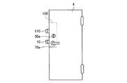
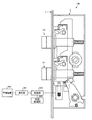
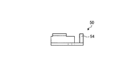
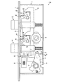
図1〜4は、実施の形態1にかかる錠前装置を設置した出入口扉の全体を示す図である。図1〜4では、出入口扉4を部屋の外部から見た正面図である。出入口扉4には、上側にデッドロッキングラッチボルト110(補助錠)が配置され、下側にはデッドロッキングラッチボルト10(主錠)が配置された錠前装置100が設置されている。この出入口扉4の外部側には、デッドロッキングラッチボルト10を移動させて解錠するために、利用者が鍵を挿入して回動操作するシリンダ30aと、利用者が回動操作することで利用者からの操作力を受付けるレバーハンドル70aが設けられている。
FIGS. 1-4 is a figure which shows the whole doorway in which the lock apparatus concerning Embodiment 1 was installed. 1-4, it is the front view which looked at the
図1〜4に示す出入口扉4が設置されている領域は、警備装置(後述)により監視(警備)されており、警備装置には、当該領域(監視領域)における警備の可否等を定めた警備モードが設定されている。
The area where the
ここで、警備モードとは、監視領域において異常検知した際の通報先への通報の可否、または監視領域に対する報知の可否などを定めたモードであり、異常を検知したときの警備装置の動作を決定するモードである。警備モードは、通報の可否および通報先、監視領域への報知の有無などによって複数のモードが存在し、代表的な警備モードとしては、警備状態、警備解除状態がある。 Here, the security mode is a mode that determines whether or not to notify the reporting destination when abnormality is detected in the monitoring area, or whether or not notification to the monitoring area is possible, and the operation of the security device when an abnormality is detected. This is the mode to decide. The security mode has a plurality of modes depending on the availability of notification, the notification destination, the presence / absence of notification to the monitoring area, and the like, and representative security modes include a security state and a security release state.
警備状態とは、主に利用者(住人)が外出中、警備を必要とする場合に設定する警備モードであり、センサによって異常を検知したときに発せられる検知信号を警備装置が受信した場合に、監視センタに異常を知らせる警報(異常検知情報)を通報する状態である。なお、警備装置の設置されている監視領域において異常を検知したことを報知する場合もある。これは、侵入者を威嚇する目的や誤報である場合に警報解除操作を促す目的で報知するものである。 The security state is a security mode that is mainly set when the user (resident) is out of the office and needs security, and when the security device receives a detection signal issued when an abnormality is detected by the sensor. In this state, an alarm (abnormality detection information) for notifying the monitoring center of an abnormality is notified. In some cases, it is notified that an abnormality has been detected in the monitoring area where the security device is installed. This is for the purpose of intimidating an intruder or for the purpose of prompting an alarm release operation in the case of misinformation.
警備解除状態とは、主に利用者が在宅中、警備を必要としない場合に設定する警備モードであり、センサによって異常を検知したときに発せられる検知信号を警備装置が受信した場合でも、監視センタへの警報(異常検知情報)の通報を行わず、監視領域における異常があるとは判断しない状態である。これは、センサにより異常を検知(人の存在の検知、扉の開閉の検知)されても、在宅中の利用者を検知したものと判断するためである。 The security release state is a security mode that is set mainly when the user is at home and does not need security. Even if the security device receives a detection signal that is detected when an abnormality is detected by the sensor, monitoring is performed. The alarm (abnormality detection information) is not reported to the center, and it is not determined that there is an abnormality in the monitoring area. This is because even if an abnormality is detected by the sensor (detection of the presence of a person, detection of opening / closing of a door), it is determined that a user at home has been detected.
また、図1〜4に示す出入口扉4は、警備モードの設定と、利用者によるシリンダ30aや内部側に設けられたサムターン(不図示)の回動操作とに基づいて、本締まり施錠状態から空締まり施錠状態にしたり、空締まり施錠状態から本締まり施錠状態にするものである。
Moreover, the
ここで、本締まり施錠状態(施錠状態)とは、出入口扉4に設けられたレバーハンドル70aを回動操作しても出入口扉4を開放不可能な状態をいう。また、空締まり施錠状態(解錠可能状態)とは、出入口扉4に設けられたレバーハンドル70aを回動操作すると、デッドロッキングラッチボルト10およびデッドロッキングラッチボルト110が出入口扉4の内部へ移動可能な状態をいう。なお、解錠状態とは、空締まり施錠状態において、出入口扉4に設けられたレバーハンドル70aを回動操作した場合であって、デッドロッキングラッチボルト10およびデッドロッキングラッチボルト110が出入口扉4の内部に挿入され、出入口扉4を押圧するだけで開放可能な状態をいう。各状態の詳細な構造については後述する。
Here, the final tightened locked state (locked state) refers to a state where the
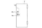
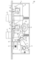
図1は、警備モードが警備解除状態に設定され、かつシリンダ30aから回動操作が行われた場合であり、空締まり施錠状態となっている。この状態で、レバーハンドル70aを回動操作すると、デッドロッキングラッチボルト10が解錠状態になるとともに、デッドロッキングラッチボルト10に連結しているデッドロッキングラッチボルト110も同様に解錠状態になり、図2に示すように、出入口扉4が開放可能な状態となる。
FIG. 1 shows a case where the security mode is set to the security release state and a rotation operation is performed from the
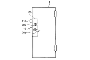
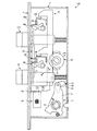
また、警備モードが警備状態に設定されたままで警備解除状態に設定されず、かつシリンダ30aから回動操作が行われた場合は、本締まり施錠状態となる。この状態で、レバーハンドル70aを回動操作しても、デッドロッキングラッチボルト10およびデッドロッキングラッチボルト110は出入口扉4の内部に挿入されることはなく、図3に示すように、出入口扉4は開放不可能な状態となる。
Further, when the security mode is set to the security state, the security release state is not set, and when the rotation operation is performed from the
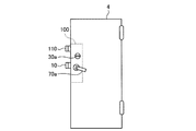
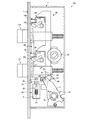
また、警備モードが警備解除状態に設定され、かつシリンダ30aから回動操作が行われなかった場合は、本締まり施錠状態となる。この状態で、レバーハンドル70aを回動操作しても、上記と同様、デッドロッキングラッチボルト10およびデッドロッキングラッチボルト110は出入口扉4の内部に挿入されることはなく、図4に示すように、出入口扉4は開放不可能な状態となる。
Further, when the security mode is set to the security release state and the rotation operation is not performed from the
つまり、警備解除状態への設定とシリンダ30aからの回動操作とが両方行われた場合にレバーハンドル70aを回動操作することで、主錠のデッドロッキングラッチボルト10と補助錠のデッドロッキングラッチボルト110を出入口扉4の内部に収納して、解錠状態にすることができる。
In other words, the
従って、警備解除状態に設定されないで、不正侵入者によって錠前装置に対する不正解錠などの不正行為がなされた場合には、デッドロッキングラッチボルト10とデッドロッキングラッチボルト110により出入口扉4が施錠状態となり、不正解錠を困難にして防犯性を向上することができる。また、警備解除状態の設定を失念してレバーハンドル70aの回動操作を行った正規の利用者に対して、その旨を気付かせて警備解除状態に設定することを促すことができる。
Therefore, when the unauthorized intruder performs an illegal act such as unauthorized unlocking of the lock device without being set to the security release state, the
更に、レバーハンドル70aを回動操作することによって、連結した二つのデッドロッキングラッチボルト10およびデッドロッキングラッチボルト110における解錠状態と空締まり施錠状態との移行動作を行うことができるため、従来の主錠と補助錠とを備えた錠前装置と比較すると、正規の利用者は二回の施解錠操作を行わずに、一回の施解錠操作で出入口扉4の開放を可能にして煩雑な施解錠操作を強要せず利便性を向上させることができる。
Furthermore, by rotating the
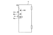
図5は、実施の形態1にかかる錠前装置の構成を示す説明図である。図5に示すように、本実施の形態にかかる錠前装置100は、出入口扉に設置されたフロント1および錠前機構2とから主に構成されており、錠前機構2における上側に補助錠であるデッドロッキングラッチボルト110(第2施解錠部)が、下側に主錠であるデッドロッキングラッチボルト10(第1施解錠部)が配置されている。
FIG. 5 is an explanatory diagram of a configuration of the lock device according to the first embodiment. As shown in FIG. 5, the
錠前機構2には、制御部510と、外部給電部520と、操作部501とが接続されており、操作部501は、監視領域に設けられている警備装置500に接続されている。なお、フロント1と錠前機構2の詳細は後述する。
A
警備装置500は、出入口扉が設置されている監視領域を監視(警備)するものであり、監視領域において異常が発生した場合は、通報先である監視センタへ異常を検知した旨の異常検知情報の通報をするものである。そして、監視センタは、監視領域の警備装置から異常検知情報の通報を受信すると、待機中の警備員に対して異常が検知された監視領域へ向かう旨の指示を出すとともに、必要に応じて警察や消防など関係機関への通報を行うことになる。なお、本実施の形態では、錠前装置100は警備装置500と有線で接続されているが、無線通信により接続された構成としてもよい。
The
操作部501は、出入口扉付近の監視領域外に設置され、警備装置500の警備モードである警備状態または警備解除状態などの設定を受付けるものであり、例えばテンキーや、接触式または非接触式のカードリーダ、タッチパネル、指紋や虹彩や静脈等の生体情報読取装置等、各種警備モードの設定を受付けられるものであればよい。
The
制御部510は、ソレノイド90(後述)に対する通電を制御するものである。すなわち、制御部510は、操作部501により警備装置500の警備モードを警備状態にする設定を受付けた場合に、ソレノイド90を通電し、警備モードを警備解除状態にする設定を受付けた場合に、ソレノイド90を非通電にする。また、制御部510は、通常時は、監視領域等に供給される電力等を操作部501やソレノイド90等に供給するが、例えば、停電時等により電力が供給できない場合には、外部給電部520によって供給された電力を操作部501に供給し、警備状態に設定した場合、外部給電部520によって供給された電力をソレノイド90に供給して通電する。
The
なお、上記では、操作部501から警備モードの設定を受付け、制御部510により受け付けた警備モードによりソレノイド90を通電または非通電にしているが、最初に利用者IDの入力を受付けてもよい。すなわち、例えば、操作部501が、利用者に固有の利用者IDの入力を受付けると、制御部510が受付けた利用者IDが記憶部(不図示)等に予め定められた利用者IDか否かを照合することによって利用者認証を行う。そして、その利用者認証に成功した場合に、警備状態または警備解除状態の設定を受付け、ソレノイド90を通電または非通電するように構成する。
In the above description, the setting of the security mode is accepted from the
外部給電部520は、制御部510に対して独立して電力を供給するものであり、例えば、電池等が該当する。停電時等により制御部510に汎用の電源からの電力供給をうけられない場合には、制御部510には外部給電部520からの電力が供給され、これにより停電時にもソレノイド90に対する通電および非通電の制御が可能となる。
The external
次に、フロント1と錠前機構2の詳細について説明する。図6は、実施の形態1にかかる錠前装置の詳細を示す説明図である。図6に示すように、本実施の形態にかかる錠前装置100は、フロント1と錠前機構2とにより構成されている。
Next, details of the front 1 and the
フロント1は、デッドロッキングラッチボルト10およびデッドロッキングラッチボルト110と、トリガーヘッド85およびトリガーヘッド185とが出入する開口部(不図示)を有し、錠前機構2の側面を覆う板状の金属板である。また、フロント1の上部と下部には、錠前機構2を出入口扉に固定するためのねじ穴(不図示)が設けられている。錠前装置100を出入口扉に設置した場合は、錠前機構2が出入口扉に埋め込まれ、フロント1が出入口扉の側面に見える状態となる。
The front 1 has a plate-like metal plate that has an opening (not shown) through which the deadlocking
錠前機構2は、デッドロッキングラッチボルト10と、デッドロッキングラッチボルト110と、連結部材20と、手動操作部30と、スライダー40と、ロッキングレバー50と、コネクティングレバー60と、ハンドル部70と、ラッチホールド80と、ラッチホールド180と、トリガーヘッド85と、トリガーヘッド185と、ソレノイド90とを主に備えている。
The
デッドロッキングラッチボルト10は、先端部12と、軸部11と、ストッパー13とによって主に構成されており、錠前装置100に対向して出入口の壁面に設けられた不図示の孔部(第1孔部)に挿脱可能となっている。また、デッドロッキングラッチボルト10は、出入口扉を本締まり施錠状態にするデッドボルトの機能と、出入口扉を空締まり施錠状態にするラッチボルトの機能を兼ねており、上記両施錠状態、および出入口扉を解錠状態にすることが可能なボルトである。
The deadlocking
ここで、本締まり施錠状態(施錠状態)とは、出入口扉に設けられたレバーハンドル70a(図1参照)を回動操作しても出入口扉を開放不可能な状態である。すなわち、フロント1の開口部を通過したデッドロッキングラッチボルト10の先端が、錠前装置100に対向して出入口の壁面に設けられた孔部(不図示)に挿入され、かつデッドロッキングラッチボルト10が孔部に保持され移動不能となった状態である。なお、図6のデッドロッキングラッチボルト10は、本締まり施錠状態となっている。
Here, the final locked state (locked state) is a state in which the doorway cannot be opened even if the
また、空締まり施錠状態(解錠可能状態)とは、出入口扉が風圧等で開放できないように仮締まりを行うことであり、出入口扉に設けられたレバーハンドル70aを回動操作すると、デッドロッキングラッチボルト10が移動可能な状態である。すなわち、デッドロッキングラッチボルト10の先端が、錠前装置100に対向して出入口の壁面に設けられた孔部(不図示)から、フロント1を通過して抜き出し可能な状態であって、出入口扉に設けられたレバーハンドル70aを回動操作すると、ハンドル部70(後述)を介して受けた利用者からの操作力(第1操作力)によって、デッドロッキングラッチボルト10が出入口の壁面の孔部からフロント1を通過してから抜き出され、出入口扉を開放できる状態である。
Further, the idle lock state (unlockable state) is to perform temporary tightening so that the doorway cannot be opened due to wind pressure or the like. When the
また、解錠状態とは、出入口扉に設けられたレバーハンドル70aを回動操作した場合であって、出入口扉を押圧するだけで開放可能な状態である。すなわち、レバーハンドル70aにより受付けた操作力をデッドロッキングラッチボルト10に伝達することで、デッドロッキングラッチボルト10を先端まで出入口扉の内部に移動させ、出入口扉を押圧するだけで開放できる状態である。
In addition, the unlocked state is a state where the
デッドロッキングラッチボルト10の軸部11は、内部が空洞となっており、上部と下部とが開放された金属性材料で形成されている。また、軸部11の一方の端面には、先端部12が接続されており、この先端部12は、施錠が行われるとフロント1の開口部(不図示)を通過して出入口の壁面の孔部に挿入される部分で、先端が略三角柱形状の金属性材料で形成されている。また、軸部11の他方の端面には、円柱形状の鉄心14が軸部11に対して移動可能に接続されている。鉄心14は、軸部11と接続されている端面と反対側の端面が錠前機構2の枠部に固定されており、デッドロッキングラッチボルト10がB方向に移動した場合、軸部11の内部に挿入されるものである。また、鉄心14の周囲にはバネ15が設けられており、デッドロッキングラッチボルト10は、バネ15により通常B方向と逆方向に付勢されている。
The
また、軸部11と先端部12との間にあるストッパー13は、バネ15により付勢されてB方向と逆方向に移動するデッドロッキングラッチボルト10を、ラッチホールド80の係止部83(後述)に当接することでデッドロッキングラッチボルト10を係止してその移動を止めるものである。これは、出入口扉が開放された状態から閉鎖される場合において、デッドロッキングラッチボルト10が出入口の壁面に当接することによる押圧力によってデッドロッキングラッチボルト10が錠前機構2の内部に挿入されるようにするため、先端部12の先端の略三角柱形状の部分のみフロント1から突出させた状態にするものである。
The
デッドロッキングラッチボルト110は、先端部112と、軸部111と、ストッパー113とによって主に構成されており、錠前装置100に対向して出入口の壁面に設けられた不図示の孔部(第2孔部)に挿脱可能となっている。また、デッドロッキングラッチボルト110は、デッドロッキングラッチボルト10と同様に、出入口扉を本締まり施錠状態にするデッドボルトの機能と、出入口扉を空締まり施錠状態にするラッチボルトの機能を兼ねており、上記両施錠状態、および出入口扉を解錠状態にすることが可能なボルトである。
The deadlocking
ここで、本締まり施錠状態、空締まり施錠状態、および解錠状態については、デッドロッキングラッチボルト10と同様である。また、デッドロッキングラッチボルト110における先端部112と、軸部111と、ストッパー113、軸部111の端面に接続されている鉄心114、鉄心114の周囲のバネ115の構成および機能については、デッドロッキングラッチボルト10の先端部12と、軸部11と、ストッパー13、鉄心14、バネ15と同様であるため説明を省略する。
Here, the final tightening locked state, the empty tightening locked state, and the unlocked state are the same as those of the deadlocking
連結部材20は、板状の金属性材料で形成された部材であって、一方の端部をデッドロッキングラッチボルト10の軸部11の内部に固定され、他方の端部をデッドロッキングラッチボルト110の軸部111の内部に固定され、デッドロッキングラッチボルト10とデッドロッキングラッチボルト110とを連結している。従って、デッドロッキングラッチボルト10がB方向に移動した場合、デッドロッキングラッチボルト110はデッドロッキングラッチボルト10の移動に連動して同じくB方向に移動する。また、デッドロッキングラッチボルト10がB方向と逆方向に移動した場合、デッドロッキングラッチボルト110はデッドロッキングラッチボルト10の移動に連動して同じくB方向と逆方向に移動する。
The connecting
手動操作部30は、出入口扉を本締まり施錠状態から空締まり施錠状態にしたり、空締まり施錠状態から本締まり施錠状態にするために、鍵を挿入して回動操作される監視領域の外部側に設けられたシリンダ30a(図1参照)や、つまみ部分を回動操作される監視領域の内部側に設けられたサムターン(不図示)が設けられている。そして、利用者が手動操作部30であるシリンダ30aまたはサムターンを回動操作すると、そのシリンダ30aまたはサムターンの回動に連動して、手動操作部30の内部に設けられた突部であるサムターンハブ31が図6におけるR1方向またはR1方向と逆方向に回動する。
The
ここで、手動操作部30からの操作力のうち、サムターンハブ31をR1方向へ回動操作する操作力(第2操作力)は、出入口扉を本締まり施錠状態から空締まり施錠状態にするものであって、サムターンハブ31をR1方向と逆方向へ回動操作する操作力(第3操作力)は、出入口扉を空締まり施錠状態から本締まり施錠状態にするものである。従って、R1方向は、出入口扉の本締まり施錠状態から空締まり施錠状態へのサムターンハブ31の回動方向となり、R1方向と逆方向は、出入口扉の空締まり施錠状態から本締まり施錠状態へのサムターンハブ31の施錠方向への回動方向となる。手動操作部30は、外出する利用者が外部側のシリンダ30aから錠前装置100の施解錠を行ったり、帰宅した利用者が内部側のサムターンから錠前装置100の施解錠を行うための回動操作に用いられる。
Here, of the operation force from the
スライダー40は、手動操作部30の回動に連動して、図6における上方であるA方向、または図6における下方であるA方向と逆方向に移動するものであって、デッドロッキングラッチボルト10の軸部11の近傍の一方の端部に板状に突出した突起部48が形成されている。図7−1は、スライダーの正面図である。図7−2は、図7−1におけるV1側から見たスライダーの側面図である。スライダー40は、金属性材料で形成されており、図7−1、7−2に示すように略板状で、部位44a、部位44b、部位45a、部位45b、部位46a、および部位46bで略90度に屈曲した形状となっている。そして、部位44aおよび部位44bの下方の空間にデッドロッキングラッチボルト10が配置され、部位45a、部位45b、部位46a、および部位46bで囲まれた空間にデッドロッキングラッチボルト110が配置される。
The
また、スライダー40は、図7−1における右側に切欠き部42が設けられており、この切欠き部42が手動操作部30のサムターンハブ31に当接することにより押圧力を受けてスライダー40は移動する。具体的には、手動操作部30のR1方向の回動に連動してサムターンハブ31がR1方向に回動すると、サムターンハブ31が切欠き部42の傾斜部42aに当接して押圧し、スライダー40は上方に向かって押圧されてA方向へ移動する。また、手動操作部30のR1方向と逆方向の回動に連動してサムターンハブ31がR1方向と逆方向に回動すると、サムターンハブ31が切欠き部42の傾斜部42bに当接して押圧し、スライダー40は下方に向かって押圧されてA方向と逆方向へ移動する。なお、図6の錠前装置100では、スライダー40がA方向と逆方向へ移動した状態である。
Further, the
また、スライダー40は、下方であるA方向と逆方向に移動すると、突起部48がコネクティングレバー60を押圧する。すなわち、スライダー40がA方向と逆方向へ移動することによって、突起部48もA方向と逆方向へ移動して、突起部48は、デッドロッキングラッチボルト10の外部方向(下方向)に移動してコネクティングレバー60を押圧する。一方、スライダー40は、上方であるA方向に移動すると、突起部48がコネクティングレバー60への押圧を解除する。すなわち、スライダー40がA方向へ移動することによって、突起部48もA方向へ移動して、突起部48は、デッドロッキングラッチボルト10の内部方向(上方向)に移動してコネクティングレバー60への押圧を解除する。なお、スライダー40は、コネクティングレバー60を押圧する場合、コネクティングレバー60をR3方向に回転させるバネ(不図示)による付勢力に対抗して押圧する。
Further, when the
また、スライダー40は、トリガーヘッド85に固定されているコ字状部材86(後述)に掛止するフック状の掛止部43が中央付近に設けられ、トリガーヘッド185に固定されているコ字状部材186(後述)に係止するフック状の係止部143が上部付近に設けられている。
In addition, the
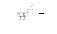
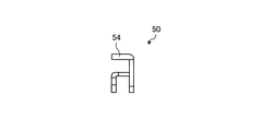
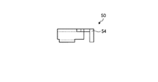
ロッキングレバー50は、金属性材料で形成されている。ロッキングレバー50は、中央付近に孔部51が設けられており、この孔部51が、錠前機構2の枠部に固定された軸部52を貫通した状態で設置されている。そして、ロッキングレバー50は、ソレノイド90の通電または非通電に連動してE方向(上方向)またはE方向と逆方向(下方向)に移動する。また、ロッキングレバー50は、ソレノイド90側(左側)の端部近傍に設けられた連結部53によりソレノイド90の鉄心92(後述)と連結されており、右側の上部の端部近傍に板状に突出した突起部54が形成されている。図8−1は、ロッキングレバーの正面図である。図8−2は、図8−1におけるV2側から見たロッキングレバーの側面図である。図8−3は、ロッキングレバーの上面図である。図8−4は、ロッキングレバーの底面図である。ロッキングレバー50は、図8−1で示しているロッキングレバー50の左側に、上面および両側面に囲まれて下部が開放された空間が形成されている。つまり、図8−2で示す図8−1におけるV2側から見たロッキングレバー50を参照すると、下部が開放されたコの字状の内部に空間が形成されていることになる。
The locking
ロッキングレバー50は、ソレノイド90が非通電にされることで鉄心92がD方向と逆方向に移動すると、孔部51に貫通している軸部52にガイドされながら上方向であるE方向に移動する。一方、ロッキングレバー50は、ソレノイド90が通電されることで鉄心92がD方向に移動すると、軸部52にガイドされながら下方向であるE方向と逆方向に移動する。
When the
また、ロッキングレバー50は、図8−1〜図8−4に示すように、ロッキングレバー50が下方向であるE方向と逆方向に移動すると、突起部54がコネクティングレバー60を押圧する。すなわち、ロッキングレバー50がE方向と逆方向に移動することによって、突起部54もE方向と逆方向へ移動して、突起部54は、デッドロッキングラッチボルト10の外部方向(下方向)に移動してコネクティングレバー60を押圧する。一方、ロッキングレバー50が上方向であるE方向に移動すると、突起部54がコネクティングレバー60への押圧を解除する。すなわち、ロッキングレバー50がE方向に移動することによって、突起部54もE方向へ移動して、突起部54は、デッドロッキングラッチボルト10の内部方向(上方向)に移動してコネクティングレバー60への押圧を解除する。なお、図6の錠前装置100は、ロッキングレバー50がE方向と反対方向に移動して、突起部54がデッドロッキングラッチボルト10の外部方向(下方向)へ移動した状態である。なお、ロッキングレバー50は、コネクティングレバー60を押圧する場合、コネクティングレバー60をR3方向に回転させるバネ(不図示)による付勢力に対抗して押圧する。
In addition, as shown in FIGS. 8A to 8D, when the locking
コネクティングレバー60は、ハンドル部70のハンドル受け部材71に回動可能に連結されている連結部61を軸にしてR3方向またはR3方向と逆方向に回動するものであって、ハンドル部70を介して受けた利用者からの操作力をデッドロッキングラッチボルト10に伝達することによってデッドロッキングラッチボルト10を移動させ出入口扉を解錠状態にする。図9は、コネクティングレバーの正面図である。コネクティングレバー60は、金属性材料で形成された板状の部材であり、連結部61の軸の周囲に設けられたバネ(不図示)により通常R3方向(デッドロッキングラッチボルト10側)に付勢されている。また、コネクティングレバー60は、デッドロッキングラッチボルト10の軸部11の端部に係合するように、窪んだ形状の係合部63が形成されている。
The connecting
また、コネクティングレバー60は、スライダー40がA方向に移動して突起部48からの押圧が解除され、かつロッキングレバー50がE方向に移動して突起部54からの押圧が解除されると、バネによる付勢力によりR3方向に回動する。この場合、突起部48および突起部54がデッドロッキングラッチボルト10の内部方向(上方向)へ移動することで、デッドロッキングラッチボルト10の軸部11に空間が設けられる。そして、コネクティングレバー60は、R3方向に回動することでその空間に入り、係合部63が軸部11の端部の位置にくるまで回動し、係合部63がデッドロッキングラッチボルト10の軸部11に係合することになる。
Further, the connecting
一方、コネクティングレバー60は、スライダー40がA方向と逆方向に移動して突起部48により押圧され、かつロッキングレバー50がE方向と逆方向に移動して突起部54により押圧されると、バネによる付勢力に対抗してR3方向と逆方向に回動する。この場合、突起部48および突起部54がデッドロッキングラッチボルト10の外部方向(下方向)へ移動することで、デッドロッキングラッチボルト10の軸部11に設けられた空間が消滅していく。そして、コネクティングレバー60は、R3方向と逆方向に回動することでその空間から押し出され、コネクティングレバー60の全体がデッドロッキングラッチボルト10の軸部11から完全に出ることで、係合部63とデッドロッキングラッチボルト10の軸部11との係合を解除する。なお、図6の錠前装置100は、係合部63とデッドロッキングラッチボルト10との係合が解除された状態である。
On the other hand, when the
コネクティングレバー60は、係合部63がデッドロッキングラッチボルト10の軸部11に係合した場合に、利用者によりレバーハンドルを回動操作されると、ハンドル部70から受付けた操作力をデッドロッキングラッチボルト10に伝達して、デッドロッキングラッチボルト10をB方向に移動させるとともに、デッドロッキングラッチボルト10に連結しているデッドロッキングラッチボルト110をB方向に移動させることで、出入口扉を解錠状態にする。また、コネクティングレバー60とデッドロッキングラッチボルト10とが係合部63で係合している状態とは、レバーハンドルからの回動操作を受付ければ出入口扉の開放可能となる状態であるため、空締まり施錠状態(解錠可能状態)となる。また、コネクティングレバー60は、係合部63とデッドロッキングラッチボルト10の軸部11との係合を解除することで、ハンドル部70から受付けた利用者からの操作力をデッドロッキングラッチボルト10に伝達不能にして、デッドロッキングラッチボルト10を移動不能にすると、出入口扉の開放が不可能な状態となるため、本締まり施錠状態となる。
When the engaging
ハンドル部70は、ハンドル受け部材71とレバーハンドル70a(図1参照)により構成されており、レバーハンドル70aは、ハンドル受け部材71に設けられた正方形のレバーハンドル孔72に差し込んで嵌合される。また、ハンドル受け部材71には、レバーハンドル孔72の周囲にバネ(不図示)が設けられており、バネの付勢力によりR4方向と逆方向に付勢されている。そして、空締まり施錠状態の出入口扉を開放するために、利用者からレバーハンドル70aをR4方向に回動する操作力を受付けた場合、ハンドル部70は、レバーハンドル孔72を軸としてR4方向に回動する。また、出入口扉を開放した後、利用者がレバーハンドル70aから手を離すと、ハンドル部70は、バネの付勢力によりR4方向と逆方向に回動し、図6の位置まで戻ることになる。そして、ハンドル部70は、利用者から受付けた操作力をデッドロッキングラッチボルト10に伝達することで、デッドロッキングラッチボルト10をB方向に移動させるとともに、デッドロッキングラッチボルト10に連結されたデッドロッキングラッチボルト110もB方向に移動させることになる。
The
ラッチホールド80は、出入口扉が開放された状態から閉鎖される場合において、デッドロッキングラッチボルト10の先端部12の先端の略三角柱形状の部分のみフロント1から突出させた状態にするために、B方向と逆方向に移動するデッドロッキングラッチボルト10のストッパー13を係止部83に係止させることでその移動を止めるものであり、錠前機構2の枠部に固定された支点81を軸にして回動可能となっている。また、ラッチホールド80は、支点81の周囲に設けられたバネ(不図示)により付勢されることでR5方向と逆方向に移動しており、図6ではトリガーヘッド85に当接することでその移動が係止されている。ラッチホールド80は、後述するコ字状部材86がC方向へ移動することでその端部87に突起82が押圧され、バネによる付勢力に対抗してR5方向に回動する。ラッチホールド80は、R5方向に回動した場合に係止部83によりデッドロッキングラッチボルト10の移動を止める。なお、図6の錠前装置100では、ラッチホールド80がR5方向と逆方向に移動した状態である。
In the case where the
ラッチホールド180は、デッドロッキングラッチボルト110の先端部112の先端の略三角柱形状の部分のみフロント1から突出させた状態にするために、B方向と逆方向に移動するデッドロッキングラッチボルト110のストッパー113を係止部183に係止させることでその移動を止めるものであり、係止部183、支点181、突起182などから形成された構成およびその機能は、ラッチホールド80と同様である。
The latch hold 180 is a stopper of the deadlocking
トリガーヘッド85は、略三角柱形状の金属性材料で形成されており、出入口扉が開放されている際に、本締まり施錠状態にならないように、スライダー40の移動を阻止するものである。トリガーヘッド85のフロント1側と反対側の端部には、断面がコの字形状の金属性材料で形成されたコ字状部材86が固定されている。トリガーヘッド85は、コ字状部材86側に設けられたバネ(不図示)により通常C方向に付勢されているが、出入口扉が閉鎖されている場合は、出入口の壁面により押圧されてC方向と逆方向に押圧されている。そして、トリガーヘッド85は、出入口扉が開放されるとともに出入口の壁面からの押圧が解除されてC方向へ移動し、出入口扉が閉鎖されるとともに出入口の壁面に押圧されてC方向と逆方向に移動して、錠前機構2の内部に挿入される。コ字状部材86の上面には、孔部が形成されており、出入口扉が閉鎖されている状態、すなわちトリガーヘッド85が錠前機構2の内部に挿入されている場合に、その孔部をスライダー40の掛止部43が通過可能となっている。また、コ字状部材86は、トリガーヘッド85のC方向の移動に連動してC方向に移動した場合、端部87がラッチホールド80の突起82をC方向に押圧する。なお、図6の錠前装置100では、トリガーヘッド85がC方向と逆方向に移動した状態である。
The
トリガーヘッド185は、出入口扉が開放されている際に、本締まり施錠状態にならないように、スライダー40の移動を阻止するものであり、コ字状部材186が固定され、端部187などから形成された構成およびその機能は、トリガーヘッド85と同様である。
The
ソレノイド90は、電磁石の一種で、電磁誘導の作用によって、電気的エネルギーを機械的エネルギーに変換するものである。ソレノイド90は、ソレノイド本体91と、鉄心92と、バネ93とにより主に構成されている。そして、ソレノイド本体91には、孔部が設けられており、その孔部に鉄心92が挿入されており、孔部における鉄心92の奥側にバネ93が配置されている。鉄心92は、その上部を連結部53によりロッキングレバー50に連結されており、バネ93からの付勢力によりD方向と逆方向に移動する。
The
鉄心92は、操作部501により警備状態の設定を受付け、制御部510によりソレノイド90が通電されると、孔部に挿入する方向、すなわち図6におけるD方向に移動していき、連結部53をD方向へ移動させる。また、操作部501により警備解除状態の設定を受付け、制御部510によりソレノイド90が非通電にされると、バネ93の付勢力により、孔部から抜き出る方向、すなわち図6におけるD方向と逆方向に移動していき、連結部53をD方向と逆方向に移動させる。
The
本実施の形態の錠前装置100は、以上のような構成となっている。本実施の形態では、コネクティングレバー60がデッドロッキングラッチボルト10の軸部11に係合している場合は、デッドロッキングラッチボルト10を移動することができ、レバーハンドルを回動操作することにより出入口扉を解錠状態にすることができる。そして、そのコネクティングレバー60は、手動操作部30により受付けた操作力により、スライダー40の突起部48がデッドロッキングラッチボルト10の内部方向(上方向)へ移動し、かつ操作部501により警備解除状態の設定を受付けてソレノイド90が非通電にされたことによりロッキングレバー50の突起部54がデッドロッキングラッチボルト10の内部方向(上方向)へ移動した場合に、デッドロッキングラッチボルト10に係合する。
The
つまり、手動操作部30からの回動操作と、操作部501による警備解除状態の設定の受付けとが両方行われた場合のみ、デッドロッキングラッチボルト10およびデッドロッキングラッチボルト110を本締まり施錠状態から空締まり施錠状態(解錠可能状態)に移行することが可能である。従って、手動操作部30からの回動操作、もしくは操作部501による警備解除状態の設定の受付けのいずれも行われない場合、またはいずれかが行われた場合は、デッドロッキングラッチボルト10およびデッドロッキングラッチボルト110を本締まり施錠状態から空締まり施錠状態(解錠可能状態)に移行することはできない。
In other words, the deadlocking
次に、錠前装置100の動作について説明する。図6に示す錠前装置100は、手動操作部30からの回動操作が行われておらず、かつ操作部501による警備解除状態の設定を受付けていない状態であり、本締まり施錠状態となっている。この状態の錠前装置100において、ハンドル部70を操作した場合の動作について、図6および図10を参照して説明する。図10は、図6に示す錠前装置においてハンドル部が操作された場合を示す図である。
Next, the operation of the
図6に示す錠前装置100は、本締まり施錠状態となっているため、コネクティングレバー60の係合部63とデッドロッキングラッチボルト10の軸部11とは係合が解除された状態で離れている。この状態において、レバーハンドル孔72に嵌合しているレバーハンドルへの利用者からの操作力を受付けると、ハンドル部70がR4方向に回動し、ハンドル部70のハンドル受け部材71と連結部61で連結されているコネクティングレバー60が移動して、図10の錠前装置100の状態になる。
Since the
つまり、図6の錠前装置100の状態で、レバーハンドルへの利用者からの操作力を受付けても、コネクティングレバー60がデッドロッキングラッチボルト10の軸部11に係合されていないため、ハンドル部70およびコネクティングレバー60は、デッドロッキングラッチボルト10を移動させることなく空転してしまう。また、デッドロッキングラッチボルト10が移動されないため、連結部材20によりデッドロッキングラッチボルト10に連結されたデッドロッキングラッチボルト110も移動されることはない。従って、錠前装置100は、デッドロッキングラッチボルト10およびデッドロッキングラッチボルト110は移動不能な状態であるため、レバーハンドルを回動操作されても出入口扉は開放されない。
That is, in the state of the
なお、この場合のコネクティングレバー60は、施解錠動作とは関係ないが、移動することによってロッキングレバー50の突起部54およびスライダー40の突起部48からの押圧が解除されるため、バネによりR3方向に多少回動する。
In this case, the connecting
次に、図6に示す本締まり施錠状態の錠前装置100から、手動操作部30を回動操作することによりスライダー40が移動した場合の動作について、図6および図11を参照して説明する。図11は、実施の形態1にかかる手動操作部を回動操作した場合の錠前装置を示す図である。
Next, an operation when the
図6に示す本締まり施錠状態の錠前装置100において、利用者から手動操作部30をR1方向へ回動する操作力を受付けると、手動操作部30に連動してサムターンハブ31がR1方向へ回動する。そして、サムターンハブ31が回動することでサムターンハブ31がスライダー40の傾斜部42aを上方に向かって押圧し、スライダー40が上方向(A方向)へ移動する。スライダー40がA方向へ移動すると、スライダー40の突起部48もA方向へ移動する。そうすると、突起部48がデッドロッキングラッチボルト10の内部方向(上方向)へ移動し、コネクティングレバー60への押圧を解除する。しかし、ロッキングレバー50の突起部54は移動しないため、コネクティングレバー60を押圧したままとなり、図11の錠前装置100の状態になる。
In the lock-locking
つまり、図6の錠前装置100の状態で、手動操作部30からの操作力を受付けるとスライダー40の突起部48は上方向に移動するが、ロッキングレバー50の突起部54は移動しないため、コネクティングレバー60の係合部63がデッドロッキングラッチボルト10の軸部11に係合されず、錠前装置100は本締まり施錠状態のままとなる。
That is, in the state of the
次に、図11に示す本締まり施錠状態の錠前装置100において、ハンドル部70を操作した場合の動作について、図11および図12を参照して説明する。図12は、図11に示す錠前装置においてハンドル部が操作された場合を示す図である。
Next, an operation when the
図11に示す錠前装置100は、本締まり施錠状態となっているため、コネクティングレバー60の係合部63とデッドロッキングラッチボルト10の軸部11とは係合が解除された状態で離れている。この状態において、レバーハンドル孔72に嵌合しているレバーハンドルへの利用者からの操作力を受付けると、ハンドル部70がR4方向に回動し、ハンドル部70のハンドル受け部材71と連結部61で連結されているコネクティングレバー60が移動して、図12の錠前装置100の状態になる。
Since the
つまり、図11の錠前装置100の状態で、レバーハンドルへの利用者からの操作力を受付けても、コネクティングレバー60がデッドロッキングラッチボルト10の軸部11に係合されていないため、ハンドル部70およびコネクティングレバー60は、デッドロッキングラッチボルト10を移動させることなく空転してしまう。また、デッドロッキングラッチボルト10が移動されないため、連結部材20によりデッドロッキングラッチボルト10に連結されたデッドロッキングラッチボルト110も移動されることはない。従って、錠前装置100は、デッドロッキングラッチボルト10およびデッドロッキングラッチボルト110が移動不能な状態であるため、レバーハンドルを回動操作されても出入口扉は開放されない。
That is, in the state of the
このように、手動操作部30からの回動操作を受付けた場合でも、操作部501による警備解除状態の設定を受付けなかった場合は、コネクティングレバー60がデッドロッキングラッチボルト10の軸部11に係合することがないため、デッドロッキングラッチボルト10は移動せず、デッドロッキングラッチボルト10に連結されたデッドロッキングラッチボルト110も移動しない。従って、本締まり施錠状態のままとなる。
As described above, even when the rotation operation from the
次に、図6に示す本締まり施錠状態の錠前装置100から、操作部501により警備解除状態の設定を受付けた場合の動作について、図6および図13を参照して説明する。図13は、実施の形態1にかかる操作部により警備解除状態の設定を受付けた場合の錠前装置を示す図である。
Next, the operation when the setting of the security release state is received by the
図6に示す本締まり施錠状態の錠前装置100において、操作部501により、利用者からの警備解除状態の設定を受付けると、ソレノイド90が非通電にされ、バネ93の付勢力により鉄心92がD方向と逆方向へ移動する。鉄心92がD方向と逆方向へ移動すると、鉄心92に連結されている連結部53がD方向と逆方向に引っ張られて、ロッキングレバー50がE方向に移動する。ロッキングレバー50がE方向に移動すると、突起部54がデッドロッキングラッチボルト10の内部方向(上方向)へ移動し、コネクティングレバー60への押圧を解除する。しかし、スライダー40の突起部48は移動しないため、コネクティングレバー60を押圧したままとなり、図13の錠前装置100の状態になる。
In the lock-
つまり、図6の錠前装置100の状態で、操作部501により警備解除状態の設定を受付けると、ロッキングレバー50の突起部54は上方向に移動するが、スライダー40の突起部48は移動しないため、コネクティングレバー60の係合部63がデッドロッキングラッチボルト10の軸部11に係合されず、錠前装置100は本締まり施錠状態のままとなる。
That is, in the state of the
次に、図13に示す本締まり施錠状態の錠前装置100において、ハンドル部70を操作した場合の動作について、図13および図14を参照して説明する。図14は、図13に示す錠前装置においてハンドル部が操作された場合を示す図である。
Next, the operation when the
図13に示す錠前装置100は、本締まり施錠状態となっているため、コネクティングレバー60の係合部63とデッドロッキングラッチボルト10の軸部11とは係合が解除された状態で離れている。この状態において、レバーハンドル孔72に嵌合しているレバーハンドルへの利用者からの操作力を受付けると、ハンドル部70がR4方向に回動し、ハンドル部70のハンドル受け部材71と連結部61で連結されているコネクティングレバー60が移動して、図14の錠前装置100の状態になる。
Since the
つまり、図13の錠前装置100の状態で、レバーハンドルへの利用者からの操作力を受付けても、コネクティングレバー60がデッドロッキングラッチボルト10の軸部11に係合されていないため、ハンドル部70およびコネクティングレバー60は、デッドロッキングラッチボルト10を移動させることなく空転してしまう。また、デッドロッキングラッチボルト10が移動されないため、連結部材20によりデッドロッキングラッチボルト10に連結されたデッドロッキングラッチボルト110も移動されることはない。従って、錠前装置100は、デッドロッキングラッチボルト10およびデッドロッキングラッチボルト110が移動不能な状態であるため、レバーハンドルを回動操作されても出入口扉は開放されない。
That is, in the state of the
このように、操作部501により警備解除状態の設定を受付けた場合でも、手動操作部30からの回動操作を受付けなかった場合は、コネクティングレバー60がデッドロッキングラッチボルト10の軸部11に係合することがないため、デッドロッキングラッチボルト10は移動せず、デッドロッキングラッチボルト10に連結されたデッドロッキングラッチボルト110も移動しない。従って、本締まり施錠状態のままとなる。
As described above, even when the setting of the security release state is accepted by the
次に、図6に示す本締まり施錠状態の錠前装置100から、手動操作部30を回動操作することによりスライダー40が移動し、操作部501により警備解除状態の設定を受付けたことによりロッキングレバー50が移動した場合の動作について、図6および図15を参照して説明する。図15は、実施の形態1にかかる手動操作部を回動操作し、かつ操作部により警備解除状態の設定を受付けた場合の錠前装置を示す図である。
Next, the
図6に示す本締まり施錠状態の錠前装置100において、利用者から手動操作部30をR1方向へ回動する操作力を受付けると、手動操作部30に連動してサムターンハブ31がR1方向へ回動する。そして、サムターンハブ31が回動することでサムターンハブ31がスライダー40の傾斜部42aを上方に向かって押圧し、スライダー40が上方向(A方向)へ移動する。スライダー40がA方向へ移動すると、スライダー40の突起部48もA方向へ移動する。そうすると、突起部48がデッドロッキングラッチボルト10の内部方向(上方向)へ移動し、コネクティングレバー60への押圧を解除する。
In the lock-locking
また、図6に示す本締まり施錠状態の錠前装置100において、操作部501により、利用者からの警備解除状態の設定を受付けると、ソレノイド90が非通電にされ、バネ93の付勢力により鉄心92がD方向と逆方向へ移動する。鉄心92がD方向と逆方向へ移動すると、鉄心92に連結されている連結部53がD方向と逆方向に引っ張られて、ロッキングレバー50がE方向に移動する。ロッキングレバー50がE方向に移動すると、突起部54がデッドロッキングラッチボルト10の内部方向(上方向)へ移動し、コネクティングレバー60への押圧を解除する。
In addition, in the lock-
そして、コネクティングレバー60は、スライダー40の突起部48およびロッキングレバー50の突起部54からの押圧が解除されると、バネ(付図示)の付勢力によりR3方向に回動し、係合部63がデッドロッキングラッチボルト10の軸部11に係合して、図15に示すように、錠前装置100が空締まり施錠状態になる。
When the pressing from the
つまり、図6の錠前装置100の状態で、手動操作部30からの操作力を受付け、かつ操作部501により警備解除状態の設定を受付けると、スライダー40の突起部48が上方向に移動するとともに、ロッキングレバー50の突起部54も上方向に移動するため、コネクティングレバー60の係合部63がデッドロッキングラッチボルト10の軸部11に係合され、錠前装置100は空締まり施錠状態となる。
That is, when the operation force from the
次に、図15に示す空締まり施錠状態の錠前装置100において、ハンドル部70を操作した場合の動作について、図15および図16を参照して説明する。図16は、図15に示す錠前装置においてハンドル部が操作された場合を示す図である。
Next, the operation when the
図15に示す錠前装置100は、空締まり施錠状態となっており、コネクティングレバー60の係合部63とデッドロッキングラッチボルト10の軸部11とが係合された状態となっている。この状態において、レバーハンドルへの利用者からの操作力を受付けると、ハンドル部70がR4方向に回動し、ハンドル部70とコネクティングレバー60は連結部61で連結されているため、コネクティングレバー60がB方向に移動する。コネクティングレバー60がB方向へ移動することで、軸部11によって係合部63に係合されているデッドロッキングラッチボルト10がバネ15の付勢力に対抗してB方向へ移動して、先端部12が錠前機構2の内部に挿入されていく。また、デッドロッキングラッチボルト10が移動すると、連結部材20によりデッドロッキングラッチボルト10に連結されたデッドロッキングラッチボルト110も、バネ115の付勢力に対抗して、デッドロッキングラッチボルト10のB方向への移動に連動して同じくB方向に移動する。そして、デッドロッキングラッチボルト10の先端部12およびデッドロッキングラッチボルト110の先端部112が完全に錠前機構2の内部に挿入されるまで移動すると、図16に示すように、フロント1からデッドロッキングラッチボルト10およびデッドロッキングラッチボルト110が突出されない状態になり、出入口扉の開放が可能となる。
The
このように、手動操作部30からの回動操作を受付け、かつ操作部501により警備解除状態の設定を受付けた場合は、コネクティングレバー60の係合部63がデッドロッキングラッチボルト10の軸部11に係合するため、ハンドル部70からの回動操作によってデッドロッキングラッチボルト10は移動し、さらにデッドロッキングラッチボルト10に連結されたデッドロッキングラッチボルト110も移動する。従って、空締まり施錠状態から解錠状態となる。
As described above, when the turning operation from the
なお、図16に示す錠前装置100において、出入口扉が開放される際、出入口の壁面からの押圧が解除されたトリガーヘッド85がバネの付勢力によりC方向へ移動するとともに、トリガーヘッド85に固定されているコ字状部材86もC方向へ移動する。コ字状部材86がC方向へ移動すると、端部87がラッチホールド80の突起82をC方向に押圧して、ラッチホールド80はR5方向に回動する。また、図16に示す錠前装置100において、出入口扉が開放される際、出入口の壁面からの押圧が解除されたトリガーヘッド185がバネの付勢力によりC方向へ移動するとともに、トリガーヘッド185に固定されているコ字状部材186もC方向へ移動する。コ字状部材186がC方向へ移動すると、端部187がラッチホールド180の突起182をC方向に押圧して、ラッチホールド180はR5方向に回動する。
In the
そして、出入口扉が開放された後に利用者がレバーハンドルから手を離すと、ハンドル部70はバネの付勢力によりR4方向と逆方向に回動し、ハンドル部70と連結部61で連結されているコネクティングレバー60もB方向と逆方向に移動する。コネクティングレバー60がB方向と逆方向に移動することによって、係合部63に軸部11で係合されてB方向へ移動していたデッドロッキングラッチボルト10と、デッドロッキングラッチボルト10に連結されているデッドロッキングラッチボルト110とが、バネ15の付勢力によりB方向と逆方向に移動する。
When the user releases the lever handle after the entrance door is opened, the
このとき、ハンドル部70は、R4方向と逆方向に回動して、図15における空締まり施錠状態のハンドル部70の位置まで戻るが、デッドロッキングラッチボルト10およびデッドロッキングラッチボルト110は、図15における空締まり施錠状態まで戻らない。
At this time, the
これは、デッドロッキングラッチボルト10がバネ15により付勢されてB方向と逆方向に移動している途中で、ストッパー13がR5方向に回動したラッチホールド80の係止部83に当接することで係止され、図15における空締まり施錠状態におけるデッドロッキングラッチボルト10の位置までは戻らず、デッドロッキングラッチボルト10の先端部12の先端の略三角柱形状の部分のみフロント1から突出させた状態となる。また、同じく、デッドロッキングラッチボルト110がバネ115により付勢されてB方向と逆方向に移動している途中で、ストッパー113がR5方向に回動したラッチホールド180の係止部183に当接することで係止され、図15における空締まり施錠状態におけるデッドロッキングラッチボルト110の位置までは戻らず、デッドロッキングラッチボルト110の先端部112の先端の略三角柱形状の部分のみフロント1から突出させた状態となる。
This is because the
これにより、レバーハンドルからの操作力を受付けなくとも、出入口扉が閉鎖される場合の出入口の壁面から略三角柱形状の部分への押圧力により、デッドロッキングラッチボルト10およびデッドロッキングラッチボルト110が一旦錠前機構2に挿入されて出入口扉が閉鎖されることになる。
Thus, even if the operating force from the lever handle is not received, the deadlocking
また、出入口扉が閉鎖される際、出入口の壁面から押圧されてトリガーヘッド85がバネの付勢力に対抗してC方向と逆方向へ移動するとともに、トリガーヘッド85に固定されているコ字状部材86もC方向と逆方向へ移動する。コ字状部材86がC方向と逆方向へ移動すると、端部87によるラッチホールド80の突起82へのC方向の押圧が解除されて、ラッチホールド80はバネの付勢力によりR5方向と逆方向に回動する。また、出入口扉が閉鎖される際、出入口の壁面から押圧されてトリガーヘッド185がバネの付勢力に対抗してC方向と逆方向へ移動するとともに、トリガーヘッド185に固定されているコ字状部材186もC方向と逆方向へ移動する。コ字状部材186がC方向と逆方向へ移動すると、端部187によるラッチホールド180の突起182へのC方向の押圧が解除されて、ラッチホールド180はバネの付勢力によりR5方向と逆方向に回動する。
Further, when the doorway is closed, the
そして、出入口の壁面からの押圧力により一旦錠前機構2に挿入されたデッドロッキングラッチボルト10は、バネ15の付勢力によりB方向と逆方向に移動して、ラッチホールド80がR5方向と逆方向へ回動したためにストッパー13が係止部83に係止されることなく、出入口の壁面の孔部に先端部12が挿入される。また、出入口の壁面からの押圧力により一旦錠前機構2に挿入されたデッドロッキングラッチボルト110は、バネ115の付勢力によりB方向と逆方向に移動して、ラッチホールド180がR5方向と逆方向へ回動したためにストッパー113が係止部183に係止されることなく、出入口の壁面の孔部に先端部112が挿入され、錠前装置100は空締まり施錠状態となる。
Then, the deadlocking
このように、実施の形態1の錠前装置100におけるデッドロッキングラッチボルト110(補助錠)では、連結部材20によりデッドロッキングラッチボルト10(主錠)に連結されている。そして、錠前装置100が空締まり施錠状態の場合に、レバーハンドル70aを回動操作すると、デッドロッキングラッチボルト10の移動に連動してデッドロッキングラッチボルト110も移動して、錠前装置100を空締まり施錠状態(解錠可能状態)から解錠状態にする。従って、正規の利用者が入退館する場合には、主錠に対する操作のみで出入口扉を施錠状態にできるため、一回の施解錠操作で出入口扉の施解錠を可能にして煩雑な施解錠操作を強要せず利便性を向上させることができる。また、不正侵入者による不正解錠などの不正行為が行われた場合は、デッドロッキングラッチボルト10(主錠)とデッドロッキングラッチボルト110(補助錠)とにより出入口扉を施錠状態にするため、不正侵入者には解錠操作を困難にし、かつ出入口扉の不正開放に対する物理的耐性を高めることで防犯性を向上できる。また、正規の利用者が警備解除状態に設定することなく、鍵による手動操作部30からの解錠を試みても出入口扉が開放されず、正規の利用者に警備の解除の失念を気付かせることができるとともに、警備の解除の失念による監視センタ等への誤報も軽減することができる。
As described above, in the deadlocking latch bolt 110 (auxiliary lock) in the
また、錠前装置100は、警備装置500における警備状態または警備解除状態の設定に従って、デッドロッキングラッチボルト10およびデッドロッキングラッチボルト110を移動させて施解錠を行うことが可能であるため、警備サービスを提供する警備会社等がデッドロッキングラッチボルト110(補助錠)の鍵を受領することが不要となり、鍵の管理負担や警備サービスの運用負担を低減することができる。
In addition, the
(実施の形態1の変形例)
実施の形態1の錠前装置100は、デッドロッキングラッチボルト10(主錠)に連動してデッドロッキングラッチボルト110(補助錠)が移動する構成となっており、デッドロッキングラッチボルト110(補助錠)が出入口扉の内部に設置されていた。従って、実施の形態1では、補助錠が設けられていることが外部側からはわからない。そこで、本実施の形態では、さらに、実施の形態1の錠前装置に、デッドロッキングラッチボルト110(補助錠)が設置されていることを不正な第三者に連想させる模造のシリンダ(ダミーシリンダ)を出入口扉4に設置したものである。
(Modification of Embodiment 1)
The
図17は、実施の形態1の変形例にかかる補助錠と主錠とを設置した出入口扉の全体を示す図である。図17は、出入口扉4を部屋の外部から見た正面図であり、デッドロッキングラッチボルト10(主錠)とデッドロッキングラッチボルト110(補助錠)とを備えた錠前装置100が出入口扉4の内部に設けられている。そして、デッドロッキングラッチボルト110が内部に設置されている位置に対応する出入口扉4の外側にダミーシリンダ200が設けられている。図18は、電気的に施解錠操作を行う補助錠が設置されていることを連想させる描画を施したダミーシリンダの一例を示す図である。なお、デッドロッキングラッチボルト10(主錠)およびデッドロッキングラッチボルト110(補助錠)の構成、機能、および施解錠動作については、実施の形態1と同様であるため説明を省略する。
FIG. 17 is a diagram illustrating the entire entrance door in which the auxiliary lock and the main lock according to the modification of the first embodiment are installed. FIG. 17 is a front view of the
ダミーシリンダ200は、出入口扉4に二つ目の錠前機構(補助錠)が設置されていることを連想させるものであり、実際の施解錠の機能は有していない。すなわち、ダミーシリンダ200は、主錠だけでなく補助錠が設置されていることを連想させる。また、ダミーシリンダ200には、図18に示すように、IC(Integrated Circuit)タグなどを所持する手が描かれた描画201を施し、このダミーシリンダ200にICタグなどを近づけることによって、非接触で電気的に施解錠操作を行うことを連想させるように構成してもよい。
The
このように、実施の形態1の変形例では、出入口扉4に描画201を施したダミーシリンダ200を設けることで、外部から侵入しようとする不正侵入者に、出入口扉4には二つ目の錠前機構である補助錠(デッドロッキングラッチボルト110)が設置されていることを視覚的に連想させることができる。従って、二つ目の錠前機構である電気錠を連想させる補助錠の設置により、不正解錠が困難であることに加え居住者の防犯意識が高いことを不正侵入者に感じさせて犯意を失わせ犯行に及ぶことに至らなくさせるよう促すことができる。
As described above, in the modification of the first embodiment, by providing the
100 錠前装置
1 フロント
2 錠前機構
10,110 デッドロッキングラッチボルト
11,111 軸部
12,112 先端部
13,113 ストッパー
14,114 鉄心
15,115 バネ
20 連結部材
30 手動操作部
30a シリンダ
31 サムターンハブ
40 スライダー
42 切欠き部
42a,42b 傾斜部
43,143 掛止部
44a,44b,45a,45b,46a,46b 部位
48 突起部
50 ロッキングレバー
51 孔部
52 軸部
53 連結部
54 突起部
60 コネクティングレバー
61 連結部
63 係合部
70 ハンドル部
70a レバーハンドル
71 ハンドル受け部材
72 レバーハンドル孔
80,180 ラッチホールド
81,181 支点
82,182 突起
83,183 係止部
85,185 トリガーヘッド
86,186 コ字状部材
87,187 端部
90 ソレノイド
91 ソレノイド本体
92 鉄心
93 バネ
200 ダミーシリンダ
201 描画
500 警備装置
501 操作部
510 制御部
520 外部給電部
DESCRIPTION OF
Claims (9)
前記錠前装置に対向して出入口の壁面に設けられた第1孔部に挿脱可能であって、前記第1孔部に挿入した状態で保持されることによって前記出入口扉を前記施錠状態にし、前記出入口扉の前記第1孔部に対して移動可能な状態にされることによって前記出入口扉を前記解錠可能状態にする第1施解錠部と、
前記錠前装置に対向して出入口の壁面に設けられた第2孔部に挿脱可能であって、前記第2孔部に挿入した状態で保持されることによって前記出入口扉を前記施錠状態にし、前記出入口扉の前記第2孔部に対して移動可能な状態にされることによって前記出入口扉を前記解錠可能状態にする第2施解錠部と、
前記第1施解錠部と前記第2施解錠部とを連結する連結部材と、
利用者から第1操作力を受付け、前記第1操作力を前記第1施解錠部に伝達することで前記第1施解錠部を移動させる開閉操作部と、
所定条件の場合、前記第1操作力を前記第1施解錠部に伝達することで、前記第1施解錠部を前記第1孔部に移動させるとともに、前記第2施解錠部を第1施解錠部の移動に連動して前記第2孔部に移動させ、前記出入口扉を前記解錠可能状態から前記解錠状態にする伝達部と、
を備え、
前記伝達部は、
前記開閉操作部に連結されており、前記第1施解錠部に係合することにより前記出入口扉を前記施錠状態または前記解錠可能状態とし、前記第1施解錠部に係合し、かつ前記第1操作力を前記第1施解錠部に伝達することで前記第1施解錠部を移動させ、前記第1施解錠部との係合を解除して前記第1操作力の前記第1施解錠部への伝達を不能にすることで前記第1施解錠部を移動不能にする係合部材を備えること、を特徴とする錠前装置。 In the lock device that is installed in the doorway, and is in a locked state where the doorway cannot be opened, an unlocked state where the doorway can be opened, or an unlockable state which can be shifted to the unlocked state,
It can be inserted into and removed from the first hole provided in the wall surface of the doorway facing the lock device, and is held in the state inserted into the first hole portion, thereby bringing the doorway into the locked state. A first locking / unlocking portion that allows the door to be unlocked by being movable with respect to the first hole of the door;
It can be inserted into and removed from the second hole provided in the wall surface of the doorway facing the lock device, and the doorway door is brought into the locked state by being held in the state inserted into the second hole portion, A second locking / unlocking portion that makes the door in the unlockable state by being movable with respect to the second hole of the door;
A connecting member for connecting the first locking / unlocking portion and the second locking / unlocking portion;
An opening / closing operation unit that receives a first operating force from a user and moves the first locking / unlocking unit by transmitting the first operating force to the first locking / unlocking unit;
In the case of a predetermined condition, by transmitting the first operating force to the first locking / unlocking portion, the first locking / unlocking portion is moved to the first hole portion, and the second locking / unlocking portion is moved to the first unlocking / unlocking portion. A transmission unit that moves to the second hole in conjunction with the movement of the lock, and changes the doorway from the unlockable state to the unlocked state,
Equipped with a,
The transmission unit is
It is connected to the opening / closing operation part, and engages with the first locking / unlocking part to make the doorway in the locked state or the unlockable state, engages with the first locking / unlocking part, and The first operating force is transmitted to the first locking / unlocking portion to move the first locking / unlocking portion, the engagement with the first locking / unlocking portion is released, and the first unlocking of the first operating force is performed. An unlocking device comprising: an engaging member that disables movement of the first locking / unlocking portion by disabling transmission to the locking portion .
前記連結部材は、前記第1施解錠部と複数の第2施解錠部とを連結し、
前記伝達部は、所定条件の場合、前記第1操作力を前記第1施解錠部に伝達することで、前記第1施解錠部を前記第1孔部に移動させるとともに、複数の第2施解錠部を第1施解錠部の移動に連動して前記第2孔部に移動させ、前記出入口扉を前記解錠可能状態から前記解錠状態にすることを特徴とする請求項1に記載の錠前装置。 A plurality of the second locking / unlocking portions are provided,
The connecting member connects the first locking / unlocking part and the plurality of second locking / unlocking parts,
In the case of a predetermined condition, the transmission unit transmits the first operating force to the first locking / unlocking unit, thereby moving the first locking / unlocking unit to the first hole and a plurality of second unlocking / unlocking units. The lock portion is moved to the second hole portion in conjunction with the movement of the first locking / unlocking portion, and the doorway door is changed from the unlockable state to the unlocked state. Locksmith device.
利用者から第2操作力を受付ける施解錠操作部と、
前記出入口扉付近に設けられ、前記警備装置によって前記監視領域の異常が検知された場合に異常検知情報を通報する警備状態、または前記警備装置によって前記監視領域の異常が検知された場合に前記異常検知情報を通報しない警備解除状態の設定を受付ける操作部と、をさらに備え、
前記係合部材は、前記所定条件として、前記施解錠操作部により前記第2操作力を受付け、かつ前記操作部により前記警備解除状態の設定を受付けた場合に、前記第1施解錠部に係合することを特徴とする請求項1または2に記載の錠前装置。 The lock device is connected to a security device that monitors the occurrence of an abnormal situation in the monitoring area where the doorway is installed,
A locking / unlocking operation unit for receiving a second operation force from the user;
Provided in the vicinity of the entrance door, and when the abnormality is detected in the monitoring area by the security device, the security state that reports abnormality detection information, or when the abnormality in the monitoring area is detected by the security device An operation unit that accepts the setting of the security release state that does not report detection information, and
The engaging member is engaged with the first locking / unlocking portion when the second operating force is received by the locking / unlocking operation portion and the setting of the security release state is received by the operation portion as the predetermined condition. The lock device according to claim 1 , wherein the lock device is combined.
前記伝達部は、
前記第1施解錠部の近傍である一方の端部に第1突起部が形成され、前記第2操作力によって押圧されることで第1方向へ移動し、前記第1突起部が前記第1施解錠部の内部方向へ移動することで前記係合部材への押圧を解除し、第3操作力によって押圧されることで第1方向と逆方向である第2方向へ移動し、前記第1突起部が前記第1施解錠部の外部方向へ移動することで前記係合部材を押圧する可動部材と、
前記ソレノイドに対する通電を制御し、前記操作部により前記警備状態から前記警備解除状態の設定を受付けた場合、前記ソレノイドを非通電にし、前記操作部により前記警備解除状態から前記警備状態の設定を受付けた場合、前記ソレノイドを通電する制御部と、
一方の端部近傍で前記鉄心に連結され、他方の端部近傍に第2突起部が形成されており、前記ソレノイドへの非通電に連動して前記第2突起部が前記第1施解錠部の内部方向へ移動することで前記係合部材への押圧を解除し、前記ソレノイドへの通電に連動して前記第2突起部が前記第1施解錠部の外部方向へ移動することで前記係合部材を押圧する押圧部材と、をさらに備え、
前記係合部材は、前記第1突起部が前記第2操作力により前記第1施解錠部の内部方向へ移動し、かつ前記第2突起部が前記ソレノイドの非通電により第1施解錠部の内部方向へ移動した場合に、前記第1施解錠部に係合することを特徴とする請求項3に記載の錠前装置。 A solenoid having an operable iron core;
The transmission unit is
A first protrusion is formed at one end in the vicinity of the first locking / unlocking part, and is moved in the first direction by being pressed by the second operating force. The first protrusion is moved to the first By moving in the internal direction of the locking / unlocking part, the pressing on the engaging member is released, and when pressed by the third operating force, the moving in the second direction opposite to the first direction, the first A movable member that presses the engaging member by moving the protruding portion toward the outside of the first locking / unlocking portion;
When energization of the solenoid is controlled and the setting of the security release state is received from the security state by the operation unit, the solenoid is de-energized and the setting of the security state is received from the security release state by the operation unit. A control unit for energizing the solenoid;
A second protrusion is formed in the vicinity of the other end near the one end, and the second protrusion is formed in the vicinity of the other end. The engagement member is released from being pressed, and the second protrusion moves in the outward direction of the first locking / unlocking portion in conjunction with energization of the solenoid. A pressing member that presses the combined member, and
In the engaging member, the first protrusion is moved inward of the first locking / unlocking part by the second operating force, and the second protrusion is not energized by the solenoid. The lock device according to claim 3 , wherein the lock device engages with the first locking / unlocking portion when moved in an internal direction.
前記係合部材は、前記可動部材および前記押圧部材からの押圧が解除された場合、前記弾性部材からの付勢力によって前記第1施解錠部に係合し、
前記可動部材および前記押圧部材は、前記弾性部材からの付勢力に対抗して、前記係合部材を押圧し、前記係合部材と前記第1施解錠部との係合を解除することを特徴とする請求項4に記載の錠前装置。 An elastic member that urges the engaging member toward the first locking / unlocking portion;
When the pressing from the movable member and the pressing member is released, the engaging member is engaged with the first locking / unlocking portion by an urging force from the elastic member,
The movable member and the pressing member press the engaging member against the urging force from the elastic member, and release the engagement between the engaging member and the first locking / unlocking portion. The lock apparatus according to claim 4 .
前記錠前装置に対向して出入口の壁面に設けられた第1孔部に挿脱可能な第1施解錠部により、前記第1孔部に挿入した状態で保持されることによって前記出入口扉を前記施錠状態にし、前記出入口扉の前記第1孔部に対して移動可能な状態にされることによって前記出入口扉を前記解錠可能状態にする第1施解錠工程と、
前記錠前装置に対向して出入口の壁面に設けられた第2孔部に挿脱可能な第2施解錠部により、前記第2孔部に挿入した状態で保持されることによって前記出入口扉を前記施錠状態にし、前記出入口扉の前記第2孔部に対して移動可能な状態にされることによって前記出入口扉を前記解錠可能状態にする第2施解錠工程と、
開閉操作部により、利用者から第1操作力を受付け、前記第1操作力を前記第1施解錠部に伝達することで前記第1施解錠部を移動させる開閉操作工程と、
所定条件の場合、伝達部により前記第1操作力を前記第1施解錠部に伝達することで、前記第1施解錠部を前記第1孔部に移動させるとともに、連結部材により前記第1施解錠部と連結する前記第2施解錠部を第1施解錠部の移動に連動して前記第2孔部に移動させ、前記出入口扉を前記解錠可能状態から前記解錠状態にする伝達工程と、
を含み、
前記伝達工程は、前記開閉操作部に連結された前記伝達部により、前記第1施解錠部に係合することにより前記出入口扉を前記施錠状態または前記解錠可能状態とし、前記伝達部に備えられた係合部材により、前記第1施解錠部に係合し、かつ前記第1操作力を前記第1施解錠部に伝達することで前記第1施解錠部を移動させ、前記第1施解錠部との係合を解除して前記第1操作力の前記第1施解錠部への伝達を不能にすることで前記第1施解錠部を移動不能にすることを特徴とする施解錠方法。 The unlocking is performed in a lock device that is installed in the doorway and that locks the doorway in an unlocked state, unlocks the doorway in an unlocked state, or unlocks in an unlockable state. In the locking method,
The doorway is held by being inserted into the first hole by a first locking / unlocking part that can be inserted into and removed from a first hole provided on the wall surface of the doorway so as to face the lock device. A first locking / unlocking step of bringing the doorway into the unlockable state by being in a locked state and being movable with respect to the first hole of the doorway;
The doorway door is held in a state of being inserted into the second hole by a second locking / unlocking part that can be inserted into and removed from the second hole provided on the wall surface of the doorway so as to face the lock device. A second locking / unlocking step of bringing the door into the unlockable state by being in a locked state and being movable with respect to the second hole of the door;
An opening / closing operation step of moving the first locking / unlocking portion by receiving a first operating force from a user by the opening / closing operation portion and transmitting the first operating force to the first locking / unlocking portion;
For a given condition, by communicating the first operating force to the first locking and unlocking unit by the transmission unit, along with moving the first locking and unlocking unit to the first hole, the first locking by connecting members A transmission step of moving the second locking / unlocking portion connected to the locking portion to the second hole portion in conjunction with the movement of the first locking / unlocking portion to change the doorway from the unlockable state to the unlocked state. When,
Only including,
In the transmission step, the transmission portion connected to the opening / closing operation portion is engaged with the first locking / unlocking portion to bring the doorway into the locked state or the unlockable state, and is provided in the transmission portion. The first locking / unlocking portion is moved by engaging the first locking / unlocking portion and transmitting the first operating force to the first locking / unlocking portion by the engaged member. A locking / unlocking method characterized by disabling the first locking / unlocking part by disengaging the locking part and disabling transmission of the first operating force to the first locking / unlocking part. .
前記錠前装置に対向して出入口の壁面に設けられた第1孔部に挿脱可能であって、前記第1孔部に挿入した状態で保持されることによって前記出入口扉を前記施錠状態にし、前記出入口扉の前記第1孔部に対して移動可能な状態にされることによって前記出入口扉を前記解錠可能状態にする第1施解錠部と、It can be inserted into and removed from the first hole provided in the wall surface of the doorway facing the lock device, and is held in the state inserted into the first hole portion, thereby bringing the doorway into the locked state. A first locking / unlocking portion that allows the door to be unlocked by being movable with respect to the first hole of the door;
前記錠前装置に対向して出入口の壁面に設けられた第2孔部に挿脱可能であって、前記第2孔部に挿入した状態で保持されることによって前記出入口扉を前記施錠状態にし、前記出入口扉の前記第2孔部に対して移動可能な状態にされることによって前記出入口扉を前記解錠可能状態にする第2施解錠部と、It can be inserted into and removed from the second hole provided in the wall surface of the doorway facing the lock device, and the doorway door is brought into the locked state by being held in the state inserted into the second hole portion, A second locking / unlocking portion that makes the door in the unlockable state by being movable with respect to the second hole of the door;
前記第1施解錠部と前記第2施解錠部とを連結する連結部材と、A connecting member for connecting the first locking / unlocking portion and the second locking / unlocking portion;
利用者から第1操作力を受付け、前記第1操作力を前記第1施解錠部に伝達することで前記第1施解錠部を移動させる開閉操作部と、An opening / closing operation unit that receives a first operating force from a user and moves the first locking / unlocking unit by transmitting the first operating force to the first locking / unlocking unit;
所定条件の場合、前記第1操作力を前記第1施解錠部に伝達することで、前記第1施解錠部を前記第1孔部に移動させるとともに、前記第2施解錠部を第1施解錠部の移動に連動して前記第2孔部に移動させ、前記出入口扉を前記解錠可能状態から前記解錠状態にする伝達部と、In the case of a predetermined condition, by transmitting the first operating force to the first locking / unlocking portion, the first locking / unlocking portion is moved to the first hole portion, and the second locking / unlocking portion is moved to the first unlocking / unlocking portion. A transmission unit that moves to the second hole in conjunction with the movement of the lock, and changes the doorway from the unlockable state to the unlocked state,
を備え、With
前記第2施解錠部は、複数設けられ、A plurality of the second locking / unlocking portions are provided,
前記連結部材は、前記第1施解錠部と複数の第2施解錠部とを連結し、The connecting member connects the first locking / unlocking part and the plurality of second locking / unlocking parts,
前記伝達部は、所定条件の場合、前記第1操作力を前記第1施解錠部に伝達することで、前記第1施解錠部を前記第1孔部に移動させるとともに、複数の第2施解錠部を第1施解錠部の移動に連動して前記第2孔部に移動させ、前記出入口扉を前記解錠可能状態から前記解錠状態にすることを特徴とする錠前装置。In the case of a predetermined condition, the transmission unit transmits the first operating force to the first locking / unlocking unit, thereby moving the first locking / unlocking unit to the first hole and a plurality of second unlocking / unlocking units. A lock device, wherein the lock portion is moved to the second hole portion in conjunction with the movement of the first lock / unlock portion, and the doorway door is changed from the unlockable state to the unlocked state.
前記錠前装置に対向して出入口の壁面に設けられた第1孔部に挿脱可能な第1施解錠部により、前記第1孔部に挿入した状態で保持されることによって前記出入口扉を前記施錠状態にし、前記出入口扉の前記第1孔部に対して移動可能な状態にされることによって前記出入口扉を前記解錠可能状態にする第1施解錠工程と、The doorway is held by being inserted into the first hole by a first locking / unlocking part that can be inserted into and removed from a first hole provided on the wall surface of the doorway so as to face the lock device. A first locking / unlocking step of bringing the doorway into the unlockable state by being in a locked state and being movable with respect to the first hole of the doorway;
前記錠前装置に対向して出入口の壁面に設けられた第2孔部に挿脱可能な第2施解錠部により、前記第2孔部に挿入した状態で保持されることによって前記出入口扉を前記施錠状態にし、前記出入口扉の前記第2孔部に対して移動可能な状態にされることによって前記出入口扉を前記解錠可能状態にする第2施解錠工程と、The doorway door is held in a state of being inserted into the second hole by a second locking / unlocking part that can be inserted into and removed from the second hole provided on the wall surface of the doorway so as to face the lock device. A second locking / unlocking step of bringing the door into the unlockable state by being in a locked state and being movable with respect to the second hole of the door;
開閉操作部により、利用者から第1操作力を受付け、前記第1操作力を前記第1施解錠部に伝達することで前記第1施解錠部を移動させる開閉操作工程と、An opening / closing operation step of moving the first locking / unlocking portion by receiving a first operating force from a user by the opening / closing operation portion and transmitting the first operating force to the first locking / unlocking portion;
所定条件の場合、伝達部により前記第1操作力を前記第1施解錠部に伝達することで、前記第1施解錠部を前記第1孔部に移動させるとともに、連結部材により前記第1施解錠部と連結する前記第2施解錠部を第1施解錠部の移動に連動して前記第2孔部に移動させ、前記出入口扉を前記解錠可能状態から前記解錠状態にする伝達工程と、In the case of a predetermined condition, the first operating force is transmitted to the first locking / unlocking portion by the transmitting portion, whereby the first locking / unlocking portion is moved to the first hole portion, and the first unlocking / unlocking portion is connected by the connecting member. A transmission step of moving the second locking / unlocking portion connected to the locking portion to the second hole portion in conjunction with the movement of the first locking / unlocking portion to change the doorway from the unlockable state to the unlocked state. When,
を含み、Including
前記第2施解錠部は、複数設けられ、A plurality of the second locking / unlocking portions are provided,
前記連結部材は、前記第1施解錠部と複数の第2施解錠部とを連結し、The connecting member connects the first locking / unlocking part and the plurality of second locking / unlocking parts,
前記伝達工程は、所定条件の場合、前記伝達部により前記第1操作力を前記第1施解錠部に伝達することで、前記第1施解錠部を前記第1孔部に移動させるとともに、前記連結部材により前記第1施解錠部に連結する複数の第2施解錠部を第1施解錠部の移動に連動して前記第2孔部に移動させ、前記出入口扉を前記解錠可能状態から前記解錠状態にすることを特徴とする施解錠方法。In the transmission step, in the case of a predetermined condition, the first operating force is transmitted to the first locking / unlocking portion by the transmitting portion to move the first locking / unlocking portion to the first hole portion, and A plurality of second locking / unlocking portions connected to the first locking / unlocking portion by a connecting member are moved to the second hole portion in conjunction with the movement of the first locking / unlocking portion, and the doorway door is moved from the unlockable state. A locking / unlocking method, wherein the unlocking state is set.
Priority Applications (1)
| Application Number | Priority Date | Filing Date | Title |
|---|---|---|---|
| JP2007256021A JP5111990B2 (en) | 2007-09-28 | 2007-09-28 | Locking device and locking / unlocking method |
Applications Claiming Priority (1)
| Application Number | Priority Date | Filing Date | Title |
|---|---|---|---|
| JP2007256021A JP5111990B2 (en) | 2007-09-28 | 2007-09-28 | Locking device and locking / unlocking method |
Publications (2)
| Publication Number | Publication Date |
|---|---|
| JP2009084873A JP2009084873A (en) | 2009-04-23 |
| JP5111990B2 true JP5111990B2 (en) | 2013-01-09 |
Family
ID=40658641
Family Applications (1)
| Application Number | Title | Priority Date | Filing Date |
|---|---|---|---|
| JP2007256021A Active JP5111990B2 (en) | 2007-09-28 | 2007-09-28 | Locking device and locking / unlocking method |
Country Status (1)
| Country | Link |
|---|---|
| JP (1) | JP5111990B2 (en) |
Cited By (1)
| Publication number | Priority date | Publication date | Assignee | Title |
|---|---|---|---|---|
| CN103132788A (en) * | 2013-03-08 | 2013-06-05 | 苏州万盛亿五金锁具有限公司 | Door lock |
Families Citing this family (2)
| Publication number | Priority date | Publication date | Assignee | Title |
|---|---|---|---|---|
| JP5550945B2 (en) * | 2009-06-26 | 2014-07-16 | 日本製紙株式会社 | Coated paper for printing |
| CN112709501B (en) * | 2020-12-02 | 2022-05-13 | 杭州萤石软件有限公司 | Electronic lock |
Family Cites Families (3)
| Publication number | Priority date | Publication date | Assignee | Title |
|---|---|---|---|---|
| JPS5965164U (en) * | 1982-10-26 | 1984-05-01 | 美和ロツク工業株式会社 | Locking/unlocking device for door locks |
| JP2002266531A (en) * | 2001-12-21 | 2002-09-18 | Mikio Kuzuu | Dummy lock |
| JP2005240405A (en) * | 2004-02-26 | 2005-09-08 | Miwa Lock Co Ltd | Double lock mechanism for lock |
-
2007
- 2007-09-28 JP JP2007256021A patent/JP5111990B2/en active Active
Cited By (2)
| Publication number | Priority date | Publication date | Assignee | Title |
|---|---|---|---|---|
| CN103132788A (en) * | 2013-03-08 | 2013-06-05 | 苏州万盛亿五金锁具有限公司 | Door lock |
| CN103132788B (en) * | 2013-03-08 | 2015-10-21 | 苏州万盛亿五金锁具有限公司 | A kind of door lock |
Also Published As
| Publication number | Publication date |
|---|---|
| JP2009084873A (en) | 2009-04-23 |
Similar Documents
| Publication | Publication Date | Title |
|---|---|---|
| US6225903B1 (en) | Alarm system armed and disarmed by a deadbolt on a door | |
| US7236085B1 (en) | Lock with remotely activated lockout feature | |
| CN101683833B (en) | Key slot device for in-vehicle auxiliary key | |
| CN101174352A (en) | Passive disarming transceiver for security systems | |
| EP1933282B1 (en) | Wireless control of security system with key-operated key fob | |
| US8633799B1 (en) | Lock with remotely activated lockout feature | |
| GB2494229A (en) | A fastening device with remote monitoring | |
| CN107810160A (en) | Solution lock key with authorization device | |
| EP1991749A1 (en) | Door locking/unlocking unit | |
| JP5258250B2 (en) | Locking device and locking / unlocking method | |
| JPH02155095A (en) | Door dead bolt interlocking type safety system | |
| JP5111990B2 (en) | Locking device and locking / unlocking method | |
| JP5171682B2 (en) | Locking / unlocking system and locking / unlocking method | |
| EP1845053B1 (en) | Landing door device of elevator | |
| JP5000998B2 (en) | Locking device and locking / unlocking method | |
| WO2010022457A1 (en) | A safe secure lock | |
| JP4897353B2 (en) | Locking device and locking / unlocking method | |
| JPH0751873B2 (en) | Safe door opening / closing control system linked to mechanical security system | |
| JP5279431B2 (en) | Locking device and locking / unlocking method | |
| US20200011091A1 (en) | Magnetic anti-theft device | |
| US20220412122A1 (en) | Actuating handle and device for securing against break-ins | |
| JP2007186955A (en) | Locking device and locking method | |
| JP4261960B2 (en) | Security device | |
| KR100858587B1 (en) | Lading door device of elevator | |
| JP3085977U (en) | Locking device |
Legal Events
| Date | Code | Title | Description |
|---|---|---|---|
| A621 | Written request for application examination |
Free format text: JAPANESE INTERMEDIATE CODE: A621 Effective date: 20100924 |
|
| A977 | Report on retrieval |
Free format text: JAPANESE INTERMEDIATE CODE: A971007 Effective date: 20120423 |
|
| A131 | Notification of reasons for refusal |
Free format text: JAPANESE INTERMEDIATE CODE: A131 Effective date: 20120508 |
|
| A521 | Request for written amendment filed |
Free format text: JAPANESE INTERMEDIATE CODE: A523 Effective date: 20120709 |
|
| TRDD | Decision of grant or rejection written | ||
| A01 | Written decision to grant a patent or to grant a registration (utility model) |
Free format text: JAPANESE INTERMEDIATE CODE: A01 Effective date: 20120918 |
|
| A01 | Written decision to grant a patent or to grant a registration (utility model) |
Free format text: JAPANESE INTERMEDIATE CODE: A01 |
|
| A61 | First payment of annual fees (during grant procedure) |
Free format text: JAPANESE INTERMEDIATE CODE: A61 Effective date: 20121010 |
|
| FPAY | Renewal fee payment (event date is renewal date of database) |
Free format text: PAYMENT UNTIL: 20151019 Year of fee payment: 3 |
|
| R150 | Certificate of patent or registration of utility model |
Ref document number: 5111990 Country of ref document: JP Free format text: JAPANESE INTERMEDIATE CODE: R150 Free format text: JAPANESE INTERMEDIATE CODE: R150 |
|
| R250 | Receipt of annual fees |
Free format text: JAPANESE INTERMEDIATE CODE: R250 |
|
| R250 | Receipt of annual fees |
Free format text: JAPANESE INTERMEDIATE CODE: R250 |
|
| R250 | Receipt of annual fees |
Free format text: JAPANESE INTERMEDIATE CODE: R250 |
|
| R250 | Receipt of annual fees |
Free format text: JAPANESE INTERMEDIATE CODE: R250 |
|
| R250 | Receipt of annual fees |
Free format text: JAPANESE INTERMEDIATE CODE: R250 |