JP5111722B2 - Electrochemical power generation - Google Patents
Electrochemical power generation Download PDFInfo
- Publication number
- JP5111722B2 JP5111722B2 JP2004081700A JP2004081700A JP5111722B2 JP 5111722 B2 JP5111722 B2 JP 5111722B2 JP 2004081700 A JP2004081700 A JP 2004081700A JP 2004081700 A JP2004081700 A JP 2004081700A JP 5111722 B2 JP5111722 B2 JP 5111722B2
- Authority
- JP
- Japan
- Prior art keywords
- fuel cell
- cathode
- anode
- supplying
- fuel
- Prior art date
- Legal status (The legal status is an assumption and is not a legal conclusion. Google has not performed a legal analysis and makes no representation as to the accuracy of the status listed.)
- Expired - Fee Related
Links
Images


Classifications
-
- H—ELECTRICITY
- H01—ELECTRIC ELEMENTS
- H01M—PROCESSES OR MEANS, e.g. BATTERIES, FOR THE DIRECT CONVERSION OF CHEMICAL ENERGY INTO ELECTRICAL ENERGY
- H01M8/00—Fuel cells; Manufacture thereof
- H01M8/04—Auxiliary arrangements, e.g. for control of pressure or for circulation of fluids
- H01M8/04298—Processes for controlling fuel cells or fuel cell systems
- H01M8/04694—Processes for controlling fuel cells or fuel cell systems characterised by variables to be controlled
- H01M8/04858—Electric variables
- H01M8/04895—Current
- H01M8/0491—Current of fuel cell stacks
-
- H—ELECTRICITY
- H01—ELECTRIC ELEMENTS
- H01M—PROCESSES OR MEANS, e.g. BATTERIES, FOR THE DIRECT CONVERSION OF CHEMICAL ENERGY INTO ELECTRICAL ENERGY
- H01M8/00—Fuel cells; Manufacture thereof
- H01M8/04—Auxiliary arrangements, e.g. for control of pressure or for circulation of fluids
- H01M8/04298—Processes for controlling fuel cells or fuel cell systems
- H01M8/043—Processes for controlling fuel cells or fuel cell systems applied during specific periods
-
- H—ELECTRICITY
- H01—ELECTRIC ELEMENTS
- H01M—PROCESSES OR MEANS, e.g. BATTERIES, FOR THE DIRECT CONVERSION OF CHEMICAL ENERGY INTO ELECTRICAL ENERGY
- H01M8/00—Fuel cells; Manufacture thereof
- H01M8/04—Auxiliary arrangements, e.g. for control of pressure or for circulation of fluids
- H01M8/04298—Processes for controlling fuel cells or fuel cell systems
- H01M8/04313—Processes for controlling fuel cells or fuel cell systems characterised by the detection or assessment of variables; characterised by the detection or assessment of failure or abnormal function
- H01M8/04537—Electric variables
- H01M8/04544—Voltage
- H01M8/04559—Voltage of fuel cell stacks
-
- H—ELECTRICITY
- H01—ELECTRIC ELEMENTS
- H01M—PROCESSES OR MEANS, e.g. BATTERIES, FOR THE DIRECT CONVERSION OF CHEMICAL ENERGY INTO ELECTRICAL ENERGY
- H01M8/00—Fuel cells; Manufacture thereof
- H01M8/10—Fuel cells with solid electrolytes
- H01M8/1004—Fuel cells with solid electrolytes characterised by membrane-electrode assemblies [MEA]
-
- Y—GENERAL TAGGING OF NEW TECHNOLOGICAL DEVELOPMENTS; GENERAL TAGGING OF CROSS-SECTIONAL TECHNOLOGIES SPANNING OVER SEVERAL SECTIONS OF THE IPC; TECHNICAL SUBJECTS COVERED BY FORMER USPC CROSS-REFERENCE ART COLLECTIONS [XRACs] AND DIGESTS
- Y02—TECHNOLOGIES OR APPLICATIONS FOR MITIGATION OR ADAPTATION AGAINST CLIMATE CHANGE
- Y02E—REDUCTION OF GREENHOUSE GAS [GHG] EMISSIONS, RELATED TO ENERGY GENERATION, TRANSMISSION OR DISTRIBUTION
- Y02E60/00—Enabling technologies; Technologies with a potential or indirect contribution to GHG emissions mitigation
- Y02E60/30—Hydrogen technology
- Y02E60/50—Fuel cells
Landscapes
- Life Sciences & Earth Sciences (AREA)
- Engineering & Computer Science (AREA)
- Manufacturing & Machinery (AREA)
- Sustainable Development (AREA)
- Sustainable Energy (AREA)
- Chemical & Material Sciences (AREA)
- Chemical Kinetics & Catalysis (AREA)
- Electrochemistry (AREA)
- General Chemical & Material Sciences (AREA)
- Fuel Cell (AREA)
Description
本発明は燃料電池に関し、特に燃料電池に逆(反転)電流をチャージする新規な装置及びその方法に関する。 The present invention relates to a fuel cell, and more particularly to a novel apparatus and method for charging a reverse (inverted) current to a fuel cell.
燃料電池は、化学エネルギーを電気エネルギーに変換することによって使用できる電気を生成する電気化学的装置である。典型的な燃料電池は、電解質(例えば、高分子電解質膜(PEM))によって分離された正負の電極を含む。典型的な直接メタノール燃料電池(DMFC)において、負極に供給される水素又はメタノールのような燃料をアノード触媒に拡散し、陽子(プロトン)及び電子に分離する。陽子はPEMを通過してカソードへ進み、電子は外部回路を通って負荷に電力を供給する。 A fuel cell is an electrochemical device that generates electricity that can be used by converting chemical energy into electrical energy. A typical fuel cell includes positive and negative electrodes separated by an electrolyte (eg, a polymer electrolyte membrane (PEM)). In a typical direct methanol fuel cell (DMFC), a fuel such as hydrogen or methanol supplied to the negative electrode is diffused into the anode catalyst and separated into protons (protons) and electrons. Protons pass through the PEM to the cathode, and the electrons supply power to the load through an external circuit.
本発明では、燃料電池の作動を周期的に中断し、中断中に電池に逆チャージ電流を供給するものである。 In the present invention, the operation of the fuel cell is periodically interrupted, and a reverse charge current is supplied to the battery during the interruption.
他の態様では、カソードで空気流量(空気流速)を増加する。 In another embodiment, the air flow rate (air flow rate) is increased at the cathode.
他の態様では、本発明は、燃料電池の作動の中断時に負荷を支持しながら燃料電池に逆電流を供給し、通常作動中に燃料電池がエネルギー蓄積要素を再チャージするものである。 In another aspect, the present invention provides a reverse current to the fuel cell while supporting the load when the fuel cell operation is interrupted, and the fuel cell recharges the energy storage element during normal operation.
本発明の他の特徴、目的及び利点は、添付図面と共に以下の詳細な説明から明らかになるだろう。 Other features, objects and advantages of the present invention will become apparent from the following detailed description, taken in conjunction with the accompanying drawings.
本発明の方法及び装置を、直接メタノール燃料電池(DMFC)に関係付けて説明する。しかしながら、本発明の方法及び装置は限定的ではないが、メタノール及びエタノールのようなカーボンベース(母体)の燃料を利用する燃料電池を含むいかなる燃料電池にも適用可能である。燃料として、純水素又は一酸化炭素(CO)で汚染された(混合された)水素を利用する水素燃料電池にも適用される。図1は、電気化学的に酸化されて電子(e−)及び陽子(H+)を生成する負電極(アノード)にメタノールが供給される作動におけるDMFC110のシステム(装置)ブロック図を示すものである。陽子は電解質100を介してカソード130へ移動する。電解質100は、固体高分子電解質膜(PEM)型であり得る。電子は外部回路(以下に説明する)を介して正電極(カソード)130に進み、ここで、PEMを介して伝導した酸素(又は酸化剤)及び陽子と反応して水と熱を生成する。酸素は、例えば、空気を流したり又は液体を介して運搬する等の種々の方法によってカソード130に供給することができる。酸化剤は、酸化するため、及び/又は、液体又は気体を介してカソードへ酸素を運搬するために用いることができる。多くの可能な酸化剤、例えば、塩素酸カリウム(KClO3)及び塩素酸ナトリウム(NaClO3)は、加熱されると、分解し、酸素を放出できる。(液状の)過酸化水素も、触媒又は酸に接触すると、分解し、酸素を放出できる。これらの酸化剤はカソードに直接接触し、電子と反応して還元反応を完了することができるが、これらはまず分解し、次いで放出された酸素がカソードに運搬され得る。
The method and apparatus of the present invention will be described in the context of a direct methanol fuel cell (DMFC). However, the method and apparatus of the present invention are applicable to any fuel cell including, but not limited to, fuel cells that utilize carbon-based fuels such as methanol and ethanol. The present invention is also applied to a hydrogen fuel cell using hydrogen contaminated (mixed) with pure hydrogen or carbon monoxide (CO) as a fuel. FIG. 1 is a system block diagram of the
電極はPEMの一方側に接触し、典型的には、白金(Pt)若しくは白金混合物やルテニウム若しくは白金ルテニウム(Pt−Ru)のような触媒で被覆されたカーボン紙の態様である。アノード及びカソードで生じる電気化学反応は以下で表すことができる:

アノードで生成した電子は、出力(電力)処理(パワープロセッシング)回路及び負荷回路(以下に説明する)を含む外部回路200を介して進む。外部回路200は、例えば、バッテリー及び/又はキャパシタを含むことができるエネルギー蓄積ユニット150を含む。燃料電池からのエネルギーは、エネルギー蓄積ユニット150の中に蓄積(セーブ)することができる。外部回路200は、必要なら、任意で、エネルギー蓄積ユニット150を適当に供給するために燃料電池からの電力を調節する第1の中間(介在)電力処理回路140を含むことができる。第1の中間出力処理回路は例えば、DC/DC変換器を含むことができる。エネルギー蓄積ユニット150に蓄積されたエネルギーは、任意の第2の出力処理回路160を介して負荷回路170(例えば、携帯電子装置)に給電するために用いることができる。第2の出力処理回路160は、負荷回路170の要求に依存してエネルギー蓄積ユニット150から出力にさらに出力調整を付与してもよく、また、例えば、DC/DC又はDC/AC変換器を含んでもよい。第1の出力処理回路140、第2の出力処理回路160及びエネルギー蓄積ユニット150の組合せによって、負荷回路170に電力を供給する。
Electrons generated at the anode travel through an
燃料電池中断を、出力処理回路180、第2の処理回路160、エネルギー蓄積ユニット150、及び制御ボックス190の相互作用によって供給することができる。回路180及び制御ボックス190は、ハードウェアモジュール、ソフトウェアモジュール又はその組合せを備えてもよい。回路180は、スイッチ又はリレー147を介して燃料電池に逆電流185を供給することによって、エネルギー蓄積ユニット150から電力を引き出す。回路180は、通常の燃料電池放電(ディスチャージ)電流に逆の電流を注入することによって、燃料電池に逆電流を供給する。従って、逆電流チャージング中のカソード電位は通常作動中のものより高く、アノード電位は通常作動中のものより低い。スイッチ又はリレー147は通常燃料電池作動用にターミナル145に接続する。スイッチ又はリレー147は、逆電流チャージング中はスイッチターミナル146に接続し、エネルギー蓄積ユニット150に蓄積されたエネルギーからの電力を回路180に供給する。エネルギー蓄積ユニット150は、逆電流チャージング中に第2の出力処理回路160を介して負荷170に電力を供給し続ける。制御ボックス190はエネルギー蓄積ユニット150から電力を引き出し、回路180がシステムに逆電流パルスをどのように供給するかを制御する。逆電流チャージは逆電流パルスの数及び各パルスの継続時間に関係し、燃料電池仕様、燃料電池作動状態(ステータス)、燃料電池性能及び外部回路作動条件に依存する。制御ボックス190は、燃料電池作動状態(例えば、燃料電池が前処理を必要とするかどうか、逆状態であるかどうか、又は、長時間作動するかどうか、パフォーマンスの遅れが観察されたかどうか)に依存して、燃料電池のパフォーマンスを改善するために、燃料電池に周期的に逆電流チャージを供給することができる。制御ボックス190は、燃料電池電圧、負荷電流175、出力処理回路160、エネルギー蓄積ユニット150のような種々の電池パフォーマンス(性能)パラメータや、ステータスライン125を介した燃料電池作動状態や、燃料供給ステータスをモニターすることによる燃料電池反転(リバーサル)や、作動継続時間、及び長期間(ロングターム)パフォーマンス低下をモニターする。
The fuel cell interruption can be provided by the interaction of the
燃料電池に印加される逆電流チャージパルスは、回路180及びスイッチ若しくはリレー147を介してのモニターされたパラメータ毎に制御することができる。例えば、制御ボックス190は、逆電流チャージング中に出力処理回路140の機能を無効にし得る。燃料電池出力電圧の低下が観察されると、制御ボックス190は初期に迅速な逆電流パルス群を電池に供給して燃料電池電力出力のレベルを増大することができる。次いで、逆電流パルスを、例えば、電池出力の観察された増加及び安定に起因して、モニターされた電池パフォーマンスによって決定されたものより低い頻度に調整することができる。一般的には、燃料電池を構築し、配置して安定な電力を負荷回路170に提供し、電源150に蓄積された余分のエネルギーをさらに供給して、負荷回路170からのピーク電力要求を満足することができる。
The reverse current charge pulse applied to the fuel cell can be controlled for each monitored parameter via
実施例
膜電極アセンブリ(MEA)は作製若しくは商用源から購入した。MEAは16cm2のアクティブ領域を有する単一セルでテストした。実験は1Mメタノール溶液及び圧縮空気を用いた行った。逆電流は典型的には負荷電流と同じだった。逆電流チャージングの継続時間は数秒から数分の範囲だった。チャージング中、セル電圧は開放回路電圧より大きく、カソードは酸化状態でありアノードは還元状態だった。
Example Membrane electrode assemblies (MEAs) were made or purchased from commercial sources. The MEA was tested in a single cell with an active area of 16cm 2. The experiment was performed using 1M methanol solution and compressed air. The reverse current was typically the same as the load current. The duration of reverse current charging ranged from a few seconds to a few minutes. During charging, the cell voltage was greater than the open circuit voltage, the cathode was in the oxidized state and the anode was in the reduced state.
MEAは以下のように準備した:Pt−Ruブラック(ジョンソン・マッセイ、ロンドン、英国)を5重量%NAFION溶液(エレクトロケム社、ウォボーン、マサチューセッツ州)と水に混合し、インクを生成する。次いで、アノード電極は、得られたインク層をプリ(予備)テフロン(登録商標)化されたカーボン紙(東レ、トレイカ、日本)に付けることによって準備した。PtRuブラック(ジョンソン・マッセイ、ロンドン、英国)の代わりにPtを用いることを除いて、カソードを準備するのに同様なプロセスを用いた。完全なMEAは、アノード電極及びカソード電極をNAFION(登録商標)(デュポン社、ウィルミントン、デラウェア州)に結合することによって作製した。燃料と空気の供給によって、2つの加熱したグラファイトブロック間でテストするために、MEAを作製した。 The MEA was prepared as follows: Pt-Ru black (Johnson Massey, London, UK) was mixed with 5 wt% NAFION solution (Electrochem, Woborne, Mass.) To form an ink. Next, an anode electrode was prepared by attaching the obtained ink layer to pre (preliminary) Teflon (registered trademark) carbon paper (Toray, Traika, Japan). A similar process was used to prepare the cathode, except that Pt was used instead of PtRu black (Johnson Massey, London, UK). A complete MEA was made by bonding the anode and cathode electrodes to NAFION® (DuPont, Wilmington, Del.). An MEA was made to test between two heated graphite blocks with a supply of fuel and air.
実施例1
この例は、本発明に従って準備した燃料電池の前処理を介してパフォーマンス(性能)の改善を証明している。図3に証明したように、逆電流を軽めにMEAに付与した後は、前処理後のMEAのパフォーマンスは、短時間逆電流チャージング前処理(図3にける曲線(b))の前のパフォーマンスと比べて大きく改善した。
Example 1
This example demonstrates the performance improvement through pretreatment of fuel cells prepared in accordance with the present invention. As proved in FIG. 3, after the reverse current is lightly applied to the MEA, the performance of the MEA after the pretreatment is the same as that of the short-time reverse current charging pretreatment (curve (b) in FIG. 3). Compared to the performance of the vastly improved.
MEAは、4.5mg/cm2のPt−Ruと3mg/cm2のPtとを用いて作製した。NAFION(登録商標)N117を電解質膜(デュポン社、ウィルミントン、デラウェア州)として用いた。新たに作製されたMEAパフォーマンス(出力電圧)を、前処理の前後の両方で、70℃で2A負荷でテストした。 The MEA was prepared using 4.5 mg / cm 2 of Pt—Ru and 3 mg / cm 2 of Pt. NAFION® N117 was used as the electrolyte membrane (DuPont, Wilmington, Del.). The newly created MEA performance (output voltage) was tested at 2A load at 70 ° C. both before and after pretreatment.
短時間逆電流チャージングを介した前処理を以下のように実施した:逆電流チャージングを、180秒にわたって計6回、2Aの18秒逆電流チャージングを周期的に付与することによってMEA上で実施した。逆電流チャージングされなかったとき、セル出力電流を2Aに維持した。電力改善は15%だった(一定出力電流状態で図2に示した15%電圧改善によって、15%電力改善された。)。逆電流チャージング後に、セルによってより高い電圧で電力が供給されたことに留意されたい。 Pretreatment via short-time reverse current charging was performed as follows: Reverse current charging was performed on the MEA by periodically applying 6 seconds over 2 seconds, 2A 18 seconds reverse current charging over 180 seconds. It carried out in. When the reverse current was not charged, the cell output current was maintained at 2A. The power improvement was 15% (the power was improved by 15% by the 15% voltage improvement shown in FIG. 2 in the constant output current state). Note that after reverse current charging, power was supplied by the cell at a higher voltage.
実施例2
本実施例は、周期的な逆電流チャージングの効果として、長期間での燃料電池パフォーマンスの低下を緩やかにすることを実証するものである。燃料電池は通常、例えば、定電流モードで一定負荷の下で作動する。このモードでの長期間作動によって、セルの出力電圧は低下する。この例では、燃料電池作動は周期的に手動で中断し、逆電流チャージングパルスを印加する。作動システムでは、これらの機能を図1のシステム、すなわち、スイッチ147が回路180及び制御ボックス190を介して位置145と146との間で周期的にスイッチされることによって備える。
Example 2
This example demonstrates that the deterioration of fuel cell performance over a long period is moderated as an effect of periodic reverse current charging. Fuel cells typically operate under constant load, for example, in constant current mode. Long term operation in this mode reduces the cell output voltage. In this example, fuel cell operation is periodically manually interrupted and a reverse current charging pulse is applied. In the actuation system, these functions are provided by the system of FIG. 1, i.e.,
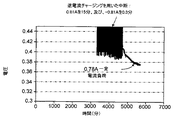
テストされたMEAは、NAFION(登録商標)N117膜を用いて、アノード側上に2.2mg/cm2(ジョンソン・マッセイ社)のPt−Ruと、カソード側上の3.3mg/cm2のPtとで準備した。テフロン(登録商標)化された東レカーボン紙を気体拡散電極として用いた。セルを42℃で550cc/minの空気流でテストした。燃料電池作動を、負荷から燃料電池の接続を切ることによって負荷電流(0.78A)を中断することを介して中断した。中断中に、逆電流パルスを外部電源回路を介して印加した。 The tested MEAs used NAFION® N117 membranes with 2.2 mg / cm 2 (Johnson Massey) Pt-Ru on the anode side and 3.3 mg / cm 2 on the cathode side. Prepared with Pt. Teflon (registered trademark) Toray carbon paper was used as a gas diffusion electrode. The cell was tested at 42 ° C. with an air flow of 550 cc / min. Fuel cell operation was interrupted via interrupting the load current (0.78 A) by disconnecting the fuel cell from the load. During the interruption, a reverse current pulse was applied via an external power supply circuit.
セルは、0.81A/15minの放電の後に−0.81A/0.3minの逆電流チャージングを行う電流の放電/チャージ(充電)サイクルの第1の期間(ピリオド)についてテストした。次いでセルを、0.78Aの一定の電流放電だけから成る第2の期間に対してテストした。図3の曲線は、両方の期間に対して、テスト下のセルの出力を示している。セルは、周期的中断及び逆電流チャージングを行った時間の間の0.5mV/hrのパフォーマンス低下に対して、定電流作動を行っていた期間に対してほぼ3mV/hrのパフォーマンス低下を経験した。 The cell was tested for a first period (period) of a discharge / charge (charge) cycle of current with 0.81 A / 15 min discharge followed by -0.81 A / 0.3 min reverse current charging. The cell was then tested for a second period consisting only of a constant current discharge of 0.78A. The curve in FIG. 3 shows the output of the cell under test for both periods. The cell experienced a performance degradation of approximately 3 mV / hr over the period of constant current operation, versus a performance degradation of 0.5 mV / hr during the period of periodic interruption and reverse current charging. did.
周期的逆電流チャージングを行っている間の期間での電流放電は、セルを一定電流負荷(0.78A)で作動中の期間より高いレベル(0.81A)で維持していたことは留意されたい。これは、十分なエネルギーが、負荷170と逆電流チャージング回路180からのエネルギー要求とを満足させるために逆電流チャージング期間中に利用可能であることを保証するために行われるものである。
Note that the current discharge during the period during the periodic reverse current charging maintained the cell at a higher level (0.81 A) than the period during which the cell was operating at a constant current load (0.78 A). I want to be. This is done to ensure that sufficient energy is available during the reverse current charging period to satisfy the
実施例3
この実施例は、セルの反転(逆転)を行った後、燃料電池パフォーマンスの回復を示すものである。燃料電池の長期間作動中に、大きなセルスタックに含まれている一又は二以上のセルの出力電圧について逆にすることが可能である。これが生じるときは、セル出力電圧は負となる。すなわち、セルの反転中に、アノードはカソードよりも高い正(電位)となる。反転についての一の共通の起因は反応物の枯渇である。セルの反転はアノード又はカソードのいずれかにおいて反応物の枯渇によって生じ得るが、アノード燃料を制限するときに最大の問題が生じる。例えば、アノード内に燃料がないと、カーボン腐食が生じ、アノード触媒は過度の酸化によってダメージを受け得る。しかしながら、本発明による電流逆(反転)手順を用いると、セルは回復し得る。
Example 3
This example shows the recovery of fuel cell performance after cell inversion. During long-term operation of the fuel cell, it is possible to reverse the output voltage of one or more cells contained in a large cell stack. When this occurs, the cell output voltage is negative. That is, during cell inversion, the anode is at a higher positive (potential) than the cathode. One common cause for inversion is reactant depletion. Although cell inversion can occur by reactant depletion at either the anode or cathode, the biggest problem arises when limiting anode fuel. For example, in the absence of fuel in the anode, carbon corrosion occurs and the anode catalyst can be damaged by excessive oxidation. However, using the current reversal (reversal) procedure according to the invention, the cell can recover.
セル電圧が負となるまで燃料なしで時々セルを作動することによって、セル反転のシミュレーションを行った。セルに逆電流を短時間付与することによって、セル低下が減少し、セルパフォーマンスがほとんど回復した。 Cell inversion was simulated by operating the cell from time to time without fuel until the cell voltage became negative. By applying a reverse current to the cell for a short time, cell degradation was reduced and cell performance was almost recovered.
以下に説明する定義された負荷(放電電流)を用いて、まずMEAをテストした。セル電圧を安定化した後、セルダメージを生じさせるのに十分の時間、セルを介して同じ電流量を付与している間、燃料ポンプを止めた。セル反転によって生じたセルダメージは、燃料源が回復した後のセル電圧が同じ出力電流密度条件の下でもともとのセル電圧より低かったならば、生じることが決まっていた。 The MEA was first tested using the defined load (discharge current) described below. After stabilizing the cell voltage, the fuel pump was turned off while applying the same amount of current through the cell for a time sufficient to cause cell damage. Cell damage caused by cell inversion has been determined to occur if the cell voltage after the fuel source is restored is lower than the original cell voltage under the same output current density conditions.
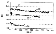
MEAは、膜(メンブレン)上にプリコートされる触媒と共にリンテック(カレッジ・ステーション社、テキサス州)から購入した。アノードは4mg/cm2のPt−Ruを含んであり、カソードは4mg/cm2のPtを含んでいた。このMEAは、アノード気体拡散電極としてテフロン(登録商標)化されたカーボン紙を、またカソード気体拡散電極として金メッシュを用いて、600cc/minの空気流を使用してテストした。図4は、70℃で1A負荷で燃料電池パフォーマンス(性能)曲線(電圧vs時間)を示す。(図4の曲線(a))の間のテスト後、同量の電流をセルから取り出している間、燃料供給ポンプを止めた。数分後、セル電圧を反転した(図4の曲線(b))。アノードは、−1.7Vのセル電圧出力を用いてカソードよりも高い正だった。燃料ポンプを入れて燃料供給を回復した後、出力電圧をセル反転前よりも大きく低下した(図4の曲線(c))。数個の短時間逆電流チャージングパルスを印加した後、セル電圧の大部分は回復した(図4の曲線(d))。 The MEA was purchased from Lintec (College Station, TX) with the catalyst precoated on the membrane. The anode contained 4 mg / cm 2 of Pt—Ru, and the cathode contained 4 mg / cm 2 of Pt. This MEA was tested using a 600 cc / min air flow using Teflon-registered carbon paper as the anode gas diffusion electrode and a gold mesh as the cathode gas diffusion electrode. FIG. 4 shows a fuel cell performance curve (voltage vs time) at 70 ° C. and 1 A load. After the test during (curve (a) in FIG. 4), the fuel supply pump was turned off while the same amount of current was drawn from the cell. After a few minutes, the cell voltage was inverted (curve (b) in FIG. 4). The anode was higher positive than the cathode with a cell voltage output of -1.7V. After the fuel pump was turned on and the fuel supply was restored, the output voltage was greatly reduced compared to before the cell inversion (curve (c) in FIG. 4). After applying several short-time reverse current charging pulses, most of the cell voltage recovered (curve (d) in FIG. 4).
実施例4
本実施例は、逆電流チャージングを増大する空気流量に結合することを示す。図5は、カソード側の空気流量の増加と共に逆電流チャージングを用いた燃料電池電圧の改善を示している。
Example 4
This example shows coupling reverse current charging to increasing air flow. FIG. 5 shows the improvement in fuel cell voltage using reverse current charging with increasing cathode side air flow.
実施例1で準備したMEAを用いると、逆電流チャージングを200cc/min(図5の曲線(c))及び600cc/min(図5の曲線(a))でテストした。逆電流チャージングの前は、MEAはより低い空気流量を有していた。逆電流チャージングの後は、MEAは、より低い空気流量でのMEA(図5の曲線(d))よりも高い空気流量(図5の曲線(b))でより高い電圧出力を有していた。 Using the MEA prepared in Example 1, reverse current charging was tested at 200 cc / min (curve (c) in FIG. 5) and 600 cc / min (curve (a) in FIG. 5). Prior to reverse current charging, the MEA had a lower air flow rate. After reverse current charging, the MEA has a higher voltage output at higher air flow (curve (b) in FIG. 5) than MEA at lower air flow (curve (d) in FIG. 5). It was.
燃料電池パフォーマンスの改善のための新規な装置及び手法を示した。当業者から、本発明の思想から逸脱することなく、本明細書に示した実施形態に対して多くの変形及び変更が可能であることは明らかである。結果として、本発明は、本明細書に開示した装置及び手法によって、かつ、添付の特許請求の範囲の精神及び範囲によって決められた各特徴及び全ての特徴並びに特徴の組合せを想到することによって把握される。 A novel apparatus and method for improving fuel cell performance is presented. It will be apparent to those skilled in the art that many modifications and variations can be made to the embodiments shown herein without departing from the spirit of the invention. As a result, the present invention can be ascertained by the devices and techniques disclosed herein and by conceiving each and every feature and combination of features determined by the spirit and scope of the appended claims. Is done.
100 電解質
110 DMFC
130 カソード
140 出力処理回路
145 ターミナル
150 エネルギー蓄積ユニット
160 出力処理回路
170 負荷回路
180 出力処理回路
190 制御ボックス
200 外部回路
130
Claims (61)
燃料を前記アノードに供給する段階と;
酸化剤を前記カソードに供給する段階と;
定電流の逆電流チャージングを前記燃料電池に周期的に供給する段階と;を備えた方法。 A method for performing electrochemical power generation using a fuel cell having an anode, an electrolyte, and a cathode, comprising:
Supplying fuel to the anode;
Supplying an oxidant to the cathode;
Periodically supplying a constant-current reverse current charging to the fuel cell.
メタノールを前記アノードに供給する段階と;
酸化剤を前記カソードに供給する段階と;
前記外部電源回路を介して定電流の逆電流チャージングを前記燃料電池に周期的に供給する段階と;を備えた方法。 A method of pretreating a fuel cell comprising an anode, an electrolyte, and a cathode, and having an external power supply circuit connecting the anode and the cathode:
Supplying methanol to the anode;
Supplying an oxidant to the cathode;
Periodically supplying a constant-current reverse-current charging to the fuel cell via the external power supply circuit.
燃料を前記アノードに供給する段階と;
酸化剤を前記カソードに供給する段階と;
前記外部電源回路を介して定電流の逆電流チャージングを前記燃料電池に周期的に供給する段階と;を備えた方法。 A fuel cell comprising an anode, an electrolyte, and a cathode, and having an external power supply circuit connecting the anode and cathode, wherein the fuel cell recovers performance when the fuel cell is in an inverted state:
Supplying fuel to the anode;
Supplying an oxidant to the cathode;
Periodically supplying a constant-current reverse-current charging to the fuel cell via the external power supply circuit.
前記燃料電池を作動して電力を供給する段階と;
前記システムの作動条件をモニターする段階と;
モニターされたシステム作動条件に基づいて、前記外部電源回路を介して定電流の逆電流チャージングを前記燃料電池に周期的に供給する段階と;を備えた方法。 A method of operating a system having a fuel cell, the fuel cell comprising an anode, an electrolyte, and a cathode, an external power supply circuit connecting the anode and the cathode, and an external load circuit connecting the anode and the cathode In the provided method:
Operating the fuel cell to provide power;
Monitoring the operating conditions of the system;
Periodically supplying a constant-current reverse current charging to the fuel cell via the external power supply circuit based on a monitored system operating condition.
前記アノードとカソードとを接続する外部電源回路と、
燃料を前記アノードに供給する第1のサプライヤーと、
酸化剤を前記カソードに供給する第2のサプライヤーと、
前記外部電源回路を介して定電流の逆電流チャージングを周期的に供給するコントローラと、を備えた燃料電池作動装置。 A fuel cell having an anode, an electrolyte, and a cathode;
An external power supply circuit connecting the anode and the cathode;
A first supplier for supplying fuel to the anode;
A second supplier for supplying an oxidant to the cathode;
And a controller that periodically supplies a reverse current charging of a constant current through the external power supply circuit.
前記アノードとカソードとを接続する外部電源回路と、
燃料を前記アノードに供給する第1のサプライヤーと、
酸化剤を前記カソードに供給する第2のサプライヤーと、
前記外部電源回路を介して定電流の逆電流チャージングを燃料電池に周期的に供給するコントローラと、を備えた燃料電池を前処理する装置。 A fuel cell having an anode, an electrolyte, and a cathode;
An external power supply circuit connecting the anode and the cathode;
A first supplier for supplying fuel to the anode;
A second supplier for supplying an oxidant to the cathode;
And a controller for periodically supplying a constant-current reverse current charging to the fuel cell via the external power supply circuit.
前記アノードとカソードとを接続する外部電源回路と、
燃料を前記アノードに供給する第1のサプライヤーと、
酸化剤を前記カソードに供給する第2のサプライヤーと、
前記外部電源回路を介して定電流の逆電流チャージングを燃料電池に周期的に供給するコントローラと、
を備えた反転して燃料電池を作動する装置。 A fuel cell having an anode, an electrolyte, and a cathode;
An external power supply circuit connecting the anode and the cathode;
A first supplier for supplying fuel to the anode;
A second supplier for supplying an oxidant to the cathode;
A controller that periodically supplies a reverse current charging of a constant current to the fuel cell via the external power supply circuit;
A device for operating a fuel cell by reversing.
前記アノードとカソードとを接続する外部電源回路と、
前記アノード及びカソードに接続される外部負荷回路と、
定電流の逆電流チャージングを燃料電池に周期的に供給するために前記外部電源回路を制御するコントローラと、を備えた燃料を電気に変換する電力装置。 A fuel cell having an anode, an electrolyte, and a cathode, wherein the fuel cell generates electricity;
An external power supply circuit connecting the anode and the cathode;
An external load circuit connected to the anode and cathode;
A controller for controlling the external power supply circuit to periodically supply a constant-current reverse current charging to the fuel cell; and a power device for converting fuel into electricity.
Applications Claiming Priority (2)
| Application Number | Priority Date | Filing Date | Title |
|---|---|---|---|
| US10/394,822 US20040185328A1 (en) | 2003-03-21 | 2003-03-21 | Chemoelectric generating |
| US10/394,822 | 2003-03-21 |
Publications (3)
| Publication Number | Publication Date |
|---|---|
| JP2004288638A JP2004288638A (en) | 2004-10-14 |
| JP2004288638A5 JP2004288638A5 (en) | 2006-05-18 |
| JP5111722B2 true JP5111722B2 (en) | 2013-01-09 |
Family
ID=32824932
Family Applications (1)
| Application Number | Title | Priority Date | Filing Date |
|---|---|---|---|
| JP2004081700A Expired - Fee Related JP5111722B2 (en) | 2003-03-21 | 2004-03-19 | Electrochemical power generation |
Country Status (8)
| Country | Link |
|---|---|
| US (1) | US20040185328A1 (en) |
| EP (1) | EP1460704B1 (en) |
| JP (1) | JP5111722B2 (en) |
| CN (1) | CN1551393B (en) |
| CA (1) | CA2461206A1 (en) |
| DE (1) | DE602004018412D1 (en) |
| HK (1) | HK1069682A1 (en) |
| TW (1) | TWI345330B (en) |
Families Citing this family (26)
| Publication number | Priority date | Publication date | Assignee | Title |
|---|---|---|---|---|
| US20070237993A1 (en) * | 2003-03-21 | 2007-10-11 | Karin Carlsson | Fuel cell reforming |
| US6962760B2 (en) * | 2003-03-25 | 2005-11-08 | The Regents Of The University Of California | Methods of conditioning direct methanol fuel cells |
| JP2005166479A (en) * | 2003-12-03 | 2005-06-23 | Nissan Motor Co Ltd | Fuel cell system |
| JP4852241B2 (en) * | 2004-12-27 | 2012-01-11 | 東芝燃料電池システム株式会社 | Operation method of fuel cell power generation system |
| JP5158398B2 (en) * | 2005-01-21 | 2013-03-06 | アイシン精機株式会社 | Operation method of fuel cell |
| DE102005051583A1 (en) * | 2005-10-27 | 2007-05-03 | Airbus Deutschland Gmbh | Fuel cell system for the supply of aircraft |
| JP5083642B2 (en) * | 2006-02-03 | 2012-11-28 | 日産自動車株式会社 | Fuel cell system |
| JP2009070691A (en) * | 2007-09-13 | 2009-04-02 | Toshiba Fuel Cell Power Systems Corp | Fuel cell system and operation method of fuel cell |
| KR101023141B1 (en) * | 2008-01-24 | 2011-03-18 | 삼성에스디아이 주식회사 | Fuel Cell System and Operating Method thereof |
| US8309259B2 (en) | 2008-05-19 | 2012-11-13 | Arizona Board Of Regents For And On Behalf Of Arizona State University | Electrochemical cell, and particularly a cell with electrodeposited fuel |
| WO2010073962A1 (en) * | 2008-12-26 | 2010-07-01 | 株式会社 東芝 | Fuel cell system and fuel cell |
| WO2010144041A1 (en) * | 2009-06-09 | 2010-12-16 | Myfc Ab | Fuel cell device and method of operating the same |
| FR2947957B1 (en) | 2009-07-09 | 2011-08-12 | Commissariat Energie Atomique | METHOD AND DEVICE FOR INCREASING THE LIFETIME OF A PROTON EXCHANGE MEMBRANE FUEL CELL |
| US8492052B2 (en) | 2009-10-08 | 2013-07-23 | Fluidic, Inc. | Electrochemical cell with spacers for flow management system |
| ES2620238T3 (en) | 2010-06-24 | 2017-06-28 | Fluidic, Inc. | Electrochemical cell with scaffold scaffold fuel anode |
| FR2961959B1 (en) * | 2010-06-29 | 2013-01-25 | Michelin Soc Tech | POWER-ENGINE AND FUEL CELL VEHICLE HAVING A SODIUM CHLORATE DECOMPOSITION REACTOR FOR SUPPLYING THE OXYGEN CELL |
| FR2961756B1 (en) * | 2010-06-29 | 2014-03-07 | Michelin Soc Tech | SYSTEM FOR PRODUCING AND SUPPLYING HYDROGEN AND SODIUM CHLORATE HAVING SODIUM CHLORIDE ELECTROLYSER FOR PRODUCING SODIUM CHLORATE |
| CN202550031U (en) | 2010-09-16 | 2012-11-21 | 流体公司 | Electrochemical battery system with gradual oxygen evolution electrode/fuel electrode |
| CN102456934B (en) | 2010-10-20 | 2016-01-20 | 流体公司 | For the battery reset process of pedestal fuel electrode |
| JP5908251B2 (en) | 2010-11-17 | 2016-04-26 | フルイディック,インク.Fluidic,Inc. | Multi-mode charging of hierarchical anode |
| JP5520905B2 (en) * | 2011-09-16 | 2014-06-11 | 東芝燃料電池システム株式会社 | Operation method of fuel cell power generation system |
| JP5520904B2 (en) * | 2011-09-16 | 2014-06-11 | 東芝燃料電池システム株式会社 | Operation method of fuel cell power generation system |
| CA3031513A1 (en) | 2016-07-22 | 2018-01-25 | Nantenergy, Inc. | Moisture and carbon dioxide management system in electrochemical cells |
| JP2020177786A (en) * | 2019-04-17 | 2020-10-29 | トヨタ自動車株式会社 | Method for recovering sulfur poisoning of anode catalyst in fuel battery cell |
| WO2020231718A1 (en) | 2019-05-10 | 2020-11-19 | Nantenergy, Inc. | Nested annular metal-air cell and systems containing same |
| CN113782785B (en) * | 2021-08-12 | 2023-05-02 | 西安交通大学 | Fuel cell carbon corrosion online diagnosis method based on carbon capacitance analysis |
Family Cites Families (13)
| Publication number | Priority date | Publication date | Assignee | Title |
|---|---|---|---|---|
| US4628010A (en) * | 1985-12-13 | 1986-12-09 | The United States Of America As Represented By The Secretary Of The Navy | Fuel cell with storable gas generator |
| JPS62216172A (en) * | 1986-03-17 | 1987-09-22 | Toshiba Corp | Manufacture of fuel cell |
| GB9412073D0 (en) * | 1994-06-16 | 1994-08-03 | British Gas Plc | Method of operating a fuel cell |
| ATE221259T1 (en) * | 1996-06-10 | 2002-08-15 | Siemens Ag | METHOD FOR OPERATING A PEM FUEL CELL SYSTEM |
| US6485851B1 (en) * | 1997-09-23 | 2002-11-26 | California Institute Of Technology | Power generation in fuel cells using liquid methanol and hydrogen peroxide |
| US6096448A (en) * | 1997-12-23 | 2000-08-01 | Ballard Power Systems Inc. | Method and apparatus for operating an electrochemical fuel cell with periodic fuel starvation at the anode |
| DE10020126A1 (en) * | 2000-04-14 | 2001-10-25 | Mannesmann Ag | Circuit for generating voltage pulses, applying to fuel cell has arrangement for switching capacitance in charging/discharge circuit while/after voltage being applied |
| DE10134193A1 (en) * | 2000-07-17 | 2002-02-07 | Vodafone Pilotentwicklung Gmbh | Fuel cell system with anode catalyst, has circuit producing voltage pulses to clear substances poisoning anode, by electrochemical oxidation |
| US20020028362A1 (en) * | 2000-09-01 | 2002-03-07 | Dennis Prediger | Anode oxidation protection in a high-temperature fuel cell |
| US20020076582A1 (en) * | 2000-12-20 | 2002-06-20 | Reiser Carl A. | Procedure for starting up a fuel cell system using a fuel purge |
| US6589686B2 (en) * | 2001-02-28 | 2003-07-08 | Ovonic Battery Company, Inc. | Method of fuel cell activation |
| WO2003067695A2 (en) * | 2002-02-06 | 2003-08-14 | Battelle Memorial Institute | Polymer electrolyte membrane fuel cell system |
| US6984464B2 (en) * | 2003-08-06 | 2006-01-10 | Utc Fuel Cells, Llc | Hydrogen passivation shut down system for a fuel cell power plant |
-
2003
- 2003-03-21 US US10/394,822 patent/US20040185328A1/en not_active Abandoned
-
2004
- 2004-03-17 CA CA002461206A patent/CA2461206A1/en not_active Abandoned
- 2004-03-19 TW TW093107509A patent/TWI345330B/en not_active IP Right Cessation
- 2004-03-19 DE DE602004018412T patent/DE602004018412D1/en not_active Expired - Lifetime
- 2004-03-19 EP EP04101150A patent/EP1460704B1/en not_active Expired - Lifetime
- 2004-03-19 JP JP2004081700A patent/JP5111722B2/en not_active Expired - Fee Related
- 2004-03-22 CN CN2004100477106A patent/CN1551393B/en not_active Expired - Fee Related
-
2005
- 2005-03-14 HK HK05102210.5A patent/HK1069682A1/en not_active IP Right Cessation
Also Published As
| Publication number | Publication date |
|---|---|
| HK1069682A1 (en) | 2005-05-27 |
| TWI345330B (en) | 2011-07-11 |
| CN1551393A (en) | 2004-12-01 |
| DE602004018412D1 (en) | 2009-01-29 |
| US20040185328A1 (en) | 2004-09-23 |
| EP1460704A1 (en) | 2004-09-22 |
| CN1551393B (en) | 2011-06-08 |
| EP1460704B1 (en) | 2008-12-17 |
| CA2461206A1 (en) | 2004-09-21 |
| JP2004288638A (en) | 2004-10-14 |
| TW200505084A (en) | 2005-02-01 |
Similar Documents
| Publication | Publication Date | Title |
|---|---|---|
| JP5111722B2 (en) | Electrochemical power generation | |
| US20070237993A1 (en) | Fuel cell reforming | |
| KR101601378B1 (en) | Fuel cell management method | |
| JP2007103115A (en) | Fuel cell system | |
| KR101795222B1 (en) | Method for accelerating activation of fuel cell | |
| KR20090119066A (en) | Method for accelerating activation of fuel cell | |
| JPH10144334A (en) | Fuel cell system power plant, and starting and stopping method therefor | |
| CN100388546C (en) | Method of operating fuel cell | |
| JP2002514345A (en) | Fuel cell with pulsating anode potential | |
| US11081713B2 (en) | Fuel cell activation method | |
| JP2004349050A (en) | Polymer electrolyte fuel cell activating method | |
| JP5303419B2 (en) | Fuel cell power generation system and operation method thereof | |
| WO2020138338A1 (en) | Fuel cell activation method and apparatus | |
| JP2003115318A (en) | Operational device and method of fuel cell | |
| US20140072887A1 (en) | Oxidation of fuel cell electrode contaminants | |
| JP2005340022A (en) | Aging method and manufacturing method of fuel cell | |
| CN112956059B (en) | Method and system for operating an electrochemical fuel cell stack with improved performance recovery | |
| CN114464846A (en) | Cathode reduction method and system of fuel cell | |
| JP2014239017A (en) | Activating method of direct methanol type fuel battery | |
| JP2008103227A (en) | Power supply device | |
| JP2009104920A (en) | Method for operating solid polymer fuel cell | |
| JP2009104921A (en) | Method for operating solid polymer fuel cell | |
| JP2005302495A (en) | Fuel cell system | |
| JP2009104919A (en) | Method for operating solid polymer fuel cell | |
| KR20070093279A (en) | Fuel cell using performance restoration apparatus |
Legal Events
| Date | Code | Title | Description |
|---|---|---|---|
| A521 | Request for written amendment filed |
Free format text: JAPANESE INTERMEDIATE CODE: A523 Effective date: 20060324 |
|
| A621 | Written request for application examination |
Free format text: JAPANESE INTERMEDIATE CODE: A621 Effective date: 20070223 |
|
| A131 | Notification of reasons for refusal |
Free format text: JAPANESE INTERMEDIATE CODE: A131 Effective date: 20100907 |
|
| A521 | Request for written amendment filed |
Free format text: JAPANESE INTERMEDIATE CODE: A523 Effective date: 20101202 |
|
| A131 | Notification of reasons for refusal |
Free format text: JAPANESE INTERMEDIATE CODE: A131 Effective date: 20110621 |
|
| A521 | Request for written amendment filed |
Free format text: JAPANESE INTERMEDIATE CODE: A523 Effective date: 20110921 |
|
| A131 | Notification of reasons for refusal |
Free format text: JAPANESE INTERMEDIATE CODE: A131 Effective date: 20120508 |
|
| A521 | Request for written amendment filed |
Free format text: JAPANESE INTERMEDIATE CODE: A523 Effective date: 20120727 |
|
| TRDD | Decision of grant or rejection written | ||
| A01 | Written decision to grant a patent or to grant a registration (utility model) |
Free format text: JAPANESE INTERMEDIATE CODE: A01 Effective date: 20120911 |
|
| A01 | Written decision to grant a patent or to grant a registration (utility model) |
Free format text: JAPANESE INTERMEDIATE CODE: A01 |
|
| A61 | First payment of annual fees (during grant procedure) |
Free format text: JAPANESE INTERMEDIATE CODE: A61 Effective date: 20121010 |
|
| FPAY | Renewal fee payment (event date is renewal date of database) |
Free format text: PAYMENT UNTIL: 20151019 Year of fee payment: 3 |
|
| R150 | Certificate of patent or registration of utility model |
Free format text: JAPANESE INTERMEDIATE CODE: R150 |
|
| R250 | Receipt of annual fees |
Free format text: JAPANESE INTERMEDIATE CODE: R250 |
|
| R250 | Receipt of annual fees |
Free format text: JAPANESE INTERMEDIATE CODE: R250 |
|
| R250 | Receipt of annual fees |
Free format text: JAPANESE INTERMEDIATE CODE: R250 |
|
| LAPS | Cancellation because of no payment of annual fees |