EP1460704B1 - Method of restoring performance of a fuel cell by providing reverse current pulses and corresponding fuel cell system - Google Patents
Method of restoring performance of a fuel cell by providing reverse current pulses and corresponding fuel cell system Download PDFInfo
- Publication number
- EP1460704B1 EP1460704B1 EP04101150A EP04101150A EP1460704B1 EP 1460704 B1 EP1460704 B1 EP 1460704B1 EP 04101150 A EP04101150 A EP 04101150A EP 04101150 A EP04101150 A EP 04101150A EP 1460704 B1 EP1460704 B1 EP 1460704B1
- Authority
- EP
- European Patent Office
- Prior art keywords
- fuel cell
- reverse current
- cathode
- oxidizer
- anode
- Prior art date
- Legal status (The legal status is an assumption and is not a legal conclusion. Google has not performed a legal analysis and makes no representation as to the accuracy of the status listed.)
- Expired - Fee Related
Links
Images
Classifications
-
- H—ELECTRICITY
- H01—ELECTRIC ELEMENTS
- H01M—PROCESSES OR MEANS, e.g. BATTERIES, FOR THE DIRECT CONVERSION OF CHEMICAL ENERGY INTO ELECTRICAL ENERGY
- H01M8/00—Fuel cells; Manufacture thereof
- H01M8/04—Auxiliary arrangements, e.g. for control of pressure or for circulation of fluids
- H01M8/04298—Processes for controlling fuel cells or fuel cell systems
- H01M8/04694—Processes for controlling fuel cells or fuel cell systems characterised by variables to be controlled
- H01M8/04858—Electric variables
- H01M8/04895—Current
- H01M8/0491—Current of fuel cell stacks
-
- H—ELECTRICITY
- H01—ELECTRIC ELEMENTS
- H01M—PROCESSES OR MEANS, e.g. BATTERIES, FOR THE DIRECT CONVERSION OF CHEMICAL ENERGY INTO ELECTRICAL ENERGY
- H01M8/00—Fuel cells; Manufacture thereof
- H01M8/04—Auxiliary arrangements, e.g. for control of pressure or for circulation of fluids
- H01M8/04298—Processes for controlling fuel cells or fuel cell systems
- H01M8/043—Processes for controlling fuel cells or fuel cell systems applied during specific periods
-
- H—ELECTRICITY
- H01—ELECTRIC ELEMENTS
- H01M—PROCESSES OR MEANS, e.g. BATTERIES, FOR THE DIRECT CONVERSION OF CHEMICAL ENERGY INTO ELECTRICAL ENERGY
- H01M8/00—Fuel cells; Manufacture thereof
- H01M8/04—Auxiliary arrangements, e.g. for control of pressure or for circulation of fluids
- H01M8/04298—Processes for controlling fuel cells or fuel cell systems
- H01M8/04313—Processes for controlling fuel cells or fuel cell systems characterised by the detection or assessment of variables; characterised by the detection or assessment of failure or abnormal function
- H01M8/04537—Electric variables
- H01M8/04544—Voltage
- H01M8/04559—Voltage of fuel cell stacks
-
- H—ELECTRICITY
- H01—ELECTRIC ELEMENTS
- H01M—PROCESSES OR MEANS, e.g. BATTERIES, FOR THE DIRECT CONVERSION OF CHEMICAL ENERGY INTO ELECTRICAL ENERGY
- H01M8/00—Fuel cells; Manufacture thereof
- H01M8/10—Fuel cells with solid electrolytes
- H01M8/1004—Fuel cells with solid electrolytes characterised by membrane-electrode assemblies [MEA]
-
- Y—GENERAL TAGGING OF NEW TECHNOLOGICAL DEVELOPMENTS; GENERAL TAGGING OF CROSS-SECTIONAL TECHNOLOGIES SPANNING OVER SEVERAL SECTIONS OF THE IPC; TECHNICAL SUBJECTS COVERED BY FORMER USPC CROSS-REFERENCE ART COLLECTIONS [XRACs] AND DIGESTS
- Y02—TECHNOLOGIES OR APPLICATIONS FOR MITIGATION OR ADAPTATION AGAINST CLIMATE CHANGE
- Y02E—REDUCTION OF GREENHOUSE GAS [GHG] EMISSIONS, RELATED TO ENERGY GENERATION, TRANSMISSION OR DISTRIBUTION
- Y02E60/00—Enabling technologies; Technologies with a potential or indirect contribution to GHG emissions mitigation
- Y02E60/30—Hydrogen technology
- Y02E60/50—Fuel cells
Definitions
- the present invention relates to fuel cells and more particularly concerns novel systems and methods for providing reverse current charging to a fuel cell.
- Fuel cells are electrochemical devices that produce usable electricity by converting chemical energy to electrical energy.
- a typical fuel cell includes positive and negative electrodes separated by an electrolyte (e.g., a polymer electrolyte membrane (PEM)).
- PEM polymer electrolyte membrane
- DMFC direct methanol fuel cell
- a fuel such as hydrogen or methanol
- supplied to the negative electrode diffuses to the anode catalyst and dissociates into protons and electrons.
- the protons pass through the PEM to the cathode, and the electrons travel through an external circuit to supply power to a load.
- the present invention is characterised by intermittently providing reverse current charging to said fuel cell through said anode and cathode.
- a system for operating a fuel cell comprising:
- the invention includes a power supply and may include an energy storage device that provides reverse current charging to the fuel cell while supporting the load when fuel cell operation is interrupted, and during normal operation the fuel cell recharges the energy storage element.
- DMFC direct methanol fuel cell
- the methods and system are applicable to any type of fuel cell including, but not limited to, fuel cells that utilize carbon based fuels, such as methanol and ethanol. It also applies to hydrogen fuel cells that utilize either pure hydrogen or hydrogen contaminated with carbon monoxide (CO) as fuel.
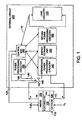
- FIG. 1 there is shown a system block diagram of a DMFC 110 in operation which methanol supplied to a negative electrode (anode) 120 that is electrochemically oxidized to produce electrons (e-) and protons (H + ). The protons move through an electrolyte 100 to the cathode 130.
- the electrolyte 100 can be in the form of a solid polymer electrolyte membrane (PEM).
- PEM solid polymer electrolyte membrane
- the electrons travel through the external circuit 200 (described below) to the positive electrode (cathode) 130, where they react with oxygen (or an oxidizer) and the protons that have been conducted through the PEM to form water and heat.
- Oxygen can be supplied to the cathode 130 by a variety of methods, such as, for example, flowing air or carrying via a liquid.
- An oxidizer can be used to oxidize and/or deliver oxygen via a fluid or gas to the cathode.
- Many possible oxidizers for example, potassium chlorate (KC10 3 ) and sodium chlorate (NaC10 3 ), can decompose and release oxygen when heated.
- Hydrogen peroxide in a liquid form also can decompose and release oxygen when contacting catalyst or acid. Although these oxidizers can directly contact the cathode and react with electrons to complete the reduction reaction, they can also be decomposed first, and then released oxygen is delivered to cathode.
- the electrodes are in contact with each side of the PEM and are typically in the form of carbon paper that is coated with a catalyst, such as platinum (Pt) or a mixture of platinum and ruthenium or a platinum ruthenium alloy (Pt-Ru).
- a catalyst such as platinum (Pt) or a mixture of platinum and ruthenium or a platinum ruthenium alloy (Pt-Ru).
- the electrons generated at the anode travel through the external circuit 200 that includes power processing circuitry and load circuitry (discu ssed below).
- the external circuit 200 includes an energy storage unit 150, which can include, e.g., a battery and/or capacitors.
- the energy from the fuel cell can be saved in the energy storage unit 150.
- the external circuit 200 optionally can include first intermediate power processing circuitry 140, which conditions the power from the fuel cell to properly supply the energy storage unit 150, if necessary.
- the first intermediate power processing circuitry can include, e.g., a DC/DC convertor.
- the energy saved in energy storage unit 150 can be used to feed load circuitry 170 (e.g., a portable electronic device) via optional second power processing circuitry 160.
- Second power processing circuitry 160 may provide further power conditioning on the output from 150 depending on the requirements of the load circuitry 170, and may include, e.g., a DC/DC or a DC/AC converter.
- the combination of first power processing circuitry 140, second power processing circuitry 160, and energy storage unit 150 provide power to the load circuit 170.
- Fuel cell interruption can be provided by the interaction of power processing circuitry 180, second processing circuitry 160, energy storage unit 150, and control box 190.
- Circuitry 180 and control box 190 may comprise a hardwa re module, a software module, or combination thereof.
- the circuitry 180 draws power from energy storage unit 150 by providing a reverse current 185 to the fuel cell via switch or relay 147.
- Circuitry 180 provides reverse current to the fuel cell by injecting a current, which is opposite to the normal fuel cell discharge current. Therefore, during reverse current charging, the cathode potential is higher than during normal operation, and the anode potential is lower than during normal operation.
- Switch or relay 147 is connected to terminal 145 for normal fuel cell operation.
- Switch or relay 147 connects to switch terminal 146 during reverse current charging, and power from saved energy in energy storage unit 150 is provided to circuitry 180.
- Energy storage unit 150 continues to provide power to load 170 via second power processing circuitry 160 during reverse current charging.
- Control box 190 draws power from energy storage unit 150 and controls how circuit 180 provides reverse current pulses to the system.
- the reverse current charge is related to the number of reverse current pulses and the duration of each pulse, and depends on the fuel cell specification, fuel cell operation status, fuel cell performance, and external circuitry operating conditions.
- the control box 190 can provide periodic reverse current charging to the fuel cell to improve fuel cell performance depending on the fuel cell operating status (i.e., whether the fuel cell requires pretreatment, is in reversal condition, or has been operating for a long time and a decay in performance has been observed).
- Control box 190 monitors a variety of cell performance parameters, such as the fuel cell voltage, load current 175, power processing circuitry 160, and energy storage unit 150, fuel cell operating status via status line 125, fuel cell reversal by monitoring the fuel supply status, operating time elapse, and long-term performance decay.
- the reverse current charge pulses applied to the fuel cell can be controlled per monitored parameters via circuitry 180 and switch or relay 147.
- the control box 190 can disable power processing circuitry 140 during reverse current charging.
- control box 190 can initially provide a rapid series of reverse current pulses to the cell to increase the level of fuel cell power output.
- the reverse current pulses can then be adjusted to be less frequent as determined by monitored cell performance, i.e., due to an observed increase and stabilization in cell output.
- the fuel cell is constructed and arranged to provide steady power to the load circuitry 170, and the extra energy saved in the power supply 150 can be further used to satisfy peak power demand from the load circuit 170.
- MEA Membrane electrode assemblies
- MEA's were prepared as follows: Pt-Ru black (Johnson Matthey, London, UK) was mixed with a 5wt% NAFION solution (Electrochem Inc, Woburn, MA) and water to form an ink. The anode electrode was then prepared by applying a layer of th e obtained ink to a pre-teflonated (10wt%) carbon paper (Toray, Torayca, Japan). A similar process was used to prepare the cathode, except that the Pt was used instead of PtRu black (Johnson Matthey, London, UK). The complete MEA was fabricated by bondin g the anode electrode and the cathode electrode to a NAFION® (Dupont, Wilmington, DE) membrane. The MEA was assembled for testing between two heated graphite blocks with fuel and air feed.
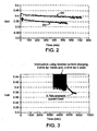
- This example demonstrates performance improvement via pretreatment of a fuel cell prepared in accordance with the invention.
- performance of the MEA after pre-treatment (curve (a) in FIG.2 ) improved significantly compared to the pe rformance prior to the brief reverse current charging pre-treatment (curve (b) in FIG.2 ).
- the MEA was fabricated in-house with 4.5mg/cm 2 of Pt-Ru and 3mg/cm 2 of Pt. NAFION® N117 was used as the electrolyte membrane (Dupont, Wilmington, DE). The performance (output voltage) of the freshly made MEA was tested at 70 °C with 2 A loading, both before and after pre-treatment.
- the pretreatment via brief reverse current charging was done as follows: the reverse current charging was carried out on the MEA by periodically applying a 2 A, 18 second reverse current pulse a total of six times over a 180 minute period. When not being reverse current charged, the cell output current was maintained at 2A. The power improvement was 15% (a 15% voltage improvement as shown in FIG.2 under constant output current conditions translates into a 15% power improvement). Note that power was provided by the cell at higher voltage after reverse current charging.
- This example demonstrates the effect of periodic reverse current charging on slowing down long-term fuel cell performance decay.
- Fuel cells are typically operated under constant load, i.e. in constant current mode. Long term operation in this mode results in a decay in the output voltage of the cell.
- the fuel cell operation was periodically interrupted manually and reverse current charging pulses were applied.
- switch 147 is periodically switched between positions 145 and 146 via circuitry 180 and control box 190.
- the MEA tested was prepared with 2.2 mg/cm 2 Pt-Ru (Johnson-Matthey) on the anode side, 3.3 mg/cm 2 Pt on the cathode side, with a NAFION® N117 membrane. Teflonized Toray carbon paper was used as the gas diffusion electrode. The cell was tested at 42 °C and with 550 cc/min air flow. The fuel cell operation was interrupted via interrupting load current by disconnecting the fuel cell from the load (0.78A). During interruption, reverse current pulses were applied via an external power supply circuit.
- the cell was tested for a first period of time with a current discharge/charge cycle of 0.81A /15 min discharge followed by -0.81A/ 0.3 min of reverse current charging. The cell was then further tested for a second period of time consisting solely of constant current discharge of 0.78A.
- the curve of FIG. 3 shows the output of the cell under test, for both periods of time. The cell experienced a performance decay of only 0.5mV/hr during the time in which periodic interruption and reverse current charging occurred vs. a performance decay of approximately 3mV/hr for period of time in which constant current operation was occurring.
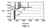
- This example describes restoration of fuel cell performance after cell reversal has occurred.
- the output voltage of one or more cells contained in a large cell stack it is possible for the output voltage of one or more cells contained in a large cell stack to become reversed. When this occurs, the cell output voltage becomes negative. That is, during cell reversal, the anode becomes more positive than the cathode.
- One common cause for reversal is reactant depletion.
- cell reversal can be caused by depletion of reactants in either the anode or cathode, the greatest problem occurs when the anode fuel is restricted. For example, without fuel in the anode, carbon corrosion will occur and the anode catalyst can be damaged by excessive oxidation. The cell can be revived, however, using the current reversal procedure in accordance with the invention.
- An MEA was first tested with a defined load (discharge current), which is described below. After the cell voltage stabilized, the fuel pump was turned off, while forcing the same amount of current through the cell, for a period of time which was long enough to cause cell damage. The cell damage caused by cell reversal was determined to have occurred if the cell voltage after the fuel source was restored was lower than the original cell voltage under the same output current density condition.
- the MEA was purchased from Lynntech (College Station, TX) with catalyst precoated on the membranes.
- the anode contained 4mg/cm 2 Pt -Ru
- the cathode contained 4mg/cm 2 Pt.
- This MEA was tested with teflonized carbon paper as the anode gas diffusion electrode and gold mesh as the cathode gas diffusion electrode using 600 cc/min of airflow.
- FIG. 4 shows the fuel cell performance curve (voltage vs. time) at 1A load at 70°C. After testing for a period of time (curve (a) in FIG. 4 ), the fuel delivery pump was turned off while the same amount of current was forced out of the cell.
- This example describes combining reverse current charging with increased air flow rate
- Example 1 Using the MEA prepared in Example 1, the reverse current charging was tested at an air flow rate of 200cc/min and 600cc/min. Before reverse current charging, the MEA had a lower voltage output at higher air flow rate. After reverse current charging, the MEA had a higher voltage output at higher air flow rate than the MEA at the lower air flow rate.
Description
- The present invention relates to fuel cells and more particularly concerns novel systems and methods for providing reverse current charging to a fuel cell.
- Fuel cells are electrochemical devices that produce usable electricity by converting chemical energy to electrical energy. A typical fuel cell includes positive and negative electrodes separated by an electrolyte (e.g., a polymer electrolyte membrane (PEM)). In a typical direct methanol fuel cell (DMFC), a fuel, such as hydrogen or methanol, supplied to the negative electrode diffuses to the anode catalyst and dissociates into protons and electrons. The protons pass through the PEM to the cathode, and the electrons travel through an external circuit to supply power to a load.
- According to
DE 10134193 ,DE 10020126 andEP-A-0701294 there is provided a method of treating a fuel cell having an anode, an electrolyte and a cathode, the method comprising: - supplying fuel to said anode;
- supplying oxidizer to said cathode;
- The present invention is characterised by
intermittently providing reverse current charging to said fuel cell through said anode and cathode. - According to a second aspect of the present invention there is provided a system for operating a fuel cell, comprising:
- a fuel cell having an anode, an electrolyte and a cathode,
- an external power supply circuit connecting said anode and cathode,
- a first supplier for supplying a fuel to said anode;
- a second supplier for supplying oxidizer to said cathode; characterised by
- a controller for intermittently providing reverse current charging to said fuel cell through said anode and cathode via said external power supply circuit.
- It is preferable to increase air flow rate at the cathode.
- The invention includes a power supply and may include an energy storage device that provides reverse current charging to the fuel cell while supporting the load when fuel cell operation is interrupted, and during normal operation the fuel cell recharges the energy storage element.
- Other features, objects, and advantages of the invention will be apparent from the following description when read in connection with the accompanying drawings in which:
-
-
FIG. 1 shows a system block diagram of an operating fuel cell in accordance with the invention; -
FIG. 2 shows a graph of voltage versus time, which demonstrates the effect of pretreatment of a fuel cell using reverse current charging according to the invention; -
FIG. 3 shows a graph of voltage versus time, which demonstrates the improvement in long-term decay of the fuel cell voltage using reverse current charging according to the invention; and -
FIG. 4 shows a graph of voltage versus time, which shows restoration of fuel cell voltage after cell reversal using reverse current charging according to the invention. - Like reference symbols in the various views indicate like elements.
- The method and system of the invention will be illustrated with reference to a direct methanol fuel cell (DMFC). However, the methods and system are applicable to any type of fuel cell including, but not limited to, fuel cells that utilize carbon based fuels, such as methanol and ethanol. It also applies to hydrogen fuel cells that utilize either pure hydrogen or hydrogen contaminated with carbon monoxide (CO) as fuel. Referring to
FIG. 1 , there is shown a system block diagram of aDMFC 110 in operation which methanol supplied to a negative electrode (anode) 120 that is electrochemically oxidized to produce electrons (e-) and protons (H+). The protons move through anelectrolyte 100 to thecathode 130. Theelectrolyte 100 can be in the form of a solid polymer electrolyte membrane (PEM). The electrons travel through the external circuit 200 (described below) to the positive electrode (cathode) 130, where they react with oxygen (or an oxidizer) and the protons that have been conducted through the PEM to form water and heat. Oxygen can be supplied to thecathode 130 by a variety of methods, such as, for example, flowing air or carrying via a liquid. An oxidizer can be used to oxidize and/or deliver oxygen via a fluid or gas to the cathode. Many possible oxidizers, for example, potassium chlorate (KC103) and sodium chlorate (NaC103), can decompose and release oxygen when heated. Hydrogen peroxide (in a liquid form) also can decompose and release oxygen when contacting catalyst or acid. Although these oxidizers can directly contact the cathode and react with electrons to complete the reduction reaction, they can also be decomposed first, and then released oxygen is delivered to cathode. - The electrodes are in contact with each side of the PEM and are typically in the form of carbon paper that is coated with a catalyst, such as platinum (Pt) or a mixture of platinum and ruthenium or a platinum ruthenium alloy (Pt-Ru). The electrochemical reactions occurring at the anode and cathode can be illustrated as follows:
Anode (oxidation half-reaction) CH3OH + H2O→ CO2 + 6H+ + 6e- Cathode (reduction half-reaction) 3/2 O2 + 6H+ + 6e- → 3H2O Net reaction CH3OH + 3/2 O2→ CO2 + 2H2O - The electrons generated at the anode travel through the
external circuit 200 that includes power processing circuitry and load circuitry (discu ssed below). Theexternal circuit 200 includes anenergy storage unit 150, which can include, e.g., a battery and/or capacitors. The energy from the fuel cell can be saved in theenergy storage unit 150. Theexternal circuit 200 optionally can include first intermediatepower processing circuitry 140, which conditions the power from the fuel cell to properly supply theenergy storage unit 150, if necessary. The first intermediate power processing circuitry can include, e.g., a DC/DC convertor. The energy saved inenergy storage unit 150 can be used to feed load circuitry 170 (e.g., a portable electronic device) via optional secondpower processing circuitry 160. Secondpower processing circuitry 160 may provide further power conditioning on the output from 150 depending on the requirements of theload circuitry 170, and may include, e.g., a DC/DC or a DC/AC converter. The combination of firstpower processing circuitry 140, secondpower processing circuitry 160, andenergy storage unit 150 provide power to theload circuit 170. - Fuel cell interruption can be provided by the interaction of
power processing circuitry 180,second processing circuitry 160,energy storage unit 150, andcontrol box 190.Circuitry 180 andcontrol box 190 may comprise a hardwa re module, a software module, or combination thereof. Thecircuitry 180 draws power fromenergy storage unit 150 by providing areverse current 185 to the fuel cell via switch orrelay 147.Circuitry 180 provides reverse current to the fuel cell by injecting a current, which is opposite to the normal fuel cell discharge current. Therefore, during reverse current charging, the cathode potential is higher than during normal operation, and the anode potential is lower than during normal operation. Switch orrelay 147 is connected toterminal 145 for normal fuel cell operation. Switch orrelay 147 connects toswitch terminal 146 during reverse current charging, and power from saved energy inenergy storage unit 150 is provided tocircuitry 180.Energy storage unit 150 continues to provide power to load 170 via secondpower processing circuitry 160 during reverse current charging.Control box 190 draws power fromenergy storage unit 150 and controls howcircuit 180 provides reverse current pulses to the system. The reverse current charge is related to the number of reverse current pulses and the duration of each pulse, and depends on the fuel cell specification, fuel cell operation status, fuel cell performance, and external circuitry operating conditions. Thecontrol box 190 can provide periodic reverse current charging to the fuel cell to improve fuel cell performance depending on the fuel cell operating status (i.e., whether the fuel cell requires pretreatment, is in reversal condition, or has been operating for a long time and a decay in performance has been observed).Control box 190 monitors a variety of cell performance parameters, such as the fuel cell voltage,load current 175,power processing circuitry 160, andenergy storage unit 150, fuel cell operating status viastatus line 125, fuel cell reversal by monitoring the fuel supply status, operating time elapse, and long-term performance decay. - The reverse current charge pulses applied to the fuel cell can be controlled per monitored parameters via
circuitry 180 and switch orrelay 147. For example, thecontrol box 190 can disablepower processing circuitry 140 during reverse current charging. When a decay in fuel cell output voltage is observed,control box 190 can initially provide a rapid series of reverse current pulses to the cell to increase the level of fuel cell power output. The reverse current pulses can then be adjusted to be less frequent as determined by monitored cell performance, i.e., due to an observed increase and stabilization in cell output. Generally, the fuel cell is constructed and arranged to provide steady power to theload circuitry 170, and the extra energy saved in thepower supply 150 can be further used to satisfy peak power demand from theload circuit 170. - Membrane electrode assemblies (MEA) were fabricated or purchased from commercial sources. An MEA was tested in a single cell with 16cm2 active area. The experiments were conducted using 1 M methanol solution and compressed air. The reverse current was typically the same as the load current. The duration of reverse current charging ranged from a few seconds to several minutes. During charging, the cell voltage was greater than the open circuit voltage, with the cathode under oxidation and the anode under reduction conditions.
- MEA's were prepared as follows: Pt-Ru black (Johnson Matthey, London, UK) was mixed with a 5wt% NAFION solution (Electrochem Inc, Woburn, MA) and water to form an ink. The anode electrode was then prepared by applying a layer of th e obtained ink to a pre-teflonated (10wt%) carbon paper (Toray, Torayca, Japan). A similar process was used to prepare the cathode, except that the Pt was used instead of PtRu black (Johnson Matthey, London, UK). The complete MEA was fabricated by bondin g the anode electrode and the cathode electrode to a NAFION® (Dupont, Wilmington, DE) membrane. The MEA was assembled for testing between two heated graphite blocks with fuel and air feed.
- This example demonstrates performance improvement via pretreatment of a fuel cell prepared in accordance with the invention. As demonstrated in
FIG.2 , after reverse current was applied briefly to a MEA, performance of the MEA after pre-treatment (curve (a) inFIG.2 ) improved significantly compared to the pe rformance prior to the brief reverse current charging pre-treatment (curve (b) inFIG.2 ). - The MEA was fabricated in-house with 4.5mg/cm2 of Pt-Ru and 3mg/cm2 of Pt. NAFION® N117 was used as the electrolyte membrane (Dupont, Wilmington, DE). The performance (output voltage) of the freshly made MEA was tested at 70 °C with 2 A loading, both before and after pre-treatment.
- The pretreatment via brief reverse current charging was done as follows: the reverse current charging was carried out on the MEA by periodically applying a 2 A, 18 second reverse current pulse a total of six times over a 180 minute period. When not being reverse current charged, the cell output current was maintained at 2A. The power improvement was 15% (a 15% voltage improvement as shown in
FIG.2 under constant output current conditions translates into a 15% power improvement). Note that power was provided by the cell at higher voltage after reverse current charging. - This example demonstrates the effect of periodic reverse current charging on slowing down long-term fuel cell performance decay. Fuel cells are typically operated under constant load, i.e. in constant current mode. Long term operation in this mode results in a decay in the output voltage of the cell. In this example, the fuel cell operation was periodically interrupted manually and reverse current charging pulses were applied. In an operating system, these functions are provided by the system of
FIG. 1 , whereswitch 147 is periodically switched betweenpositions circuitry 180 andcontrol box 190. - The MEA tested was prepared with 2.2 mg/cm2 Pt-Ru (Johnson-Matthey) on the anode side, 3.3 mg/cm2 Pt on the cathode side, with a NAFION® N117 membrane. Teflonized Toray carbon paper was used as the gas diffusion electrode. The cell was tested at 42 °C and with 550 cc/min air flow. The fuel cell operation was interrupted via interrupting load current by disconnecting the fuel cell from the load (0.78A). During interruption, reverse current pulses were applied via an external power supply circuit.
- The cell was tested for a first period of time with a current discharge/charge cycle of 0.81A /15 min discharge followed by -0.81A/ 0.3 min of reverse current charging. The cell was then further tested for a second period of time consisting solely of constant current discharge of 0.78A. The curve of
FIG. 3 shows the output of the cell under test, for both periods of time. The cell experienced a performance decay of only 0.5mV/hr during the time in which periodic interruption and reverse current charging occurred vs. a performance decay of approximately 3mV/hr for period of time in which constant current operation was occurring. - Note that the current discharge for the period of time during which periodic r everse current charging was occurring was maintained at a higher level (0.81A) than it was during the period of time when the cell was operated under constant current load (0.78A). This is done to ensure that sufficient energy is available during the reverse current charging period to satisfy the
load 170 and the energy demand from the reversecurrent charging circuit 180. - This example describes restoration of fuel cell performance after cell reversal has occurred. During long term operation of a fuel cell, it is possible for the output voltage of one or more cells contained in a large cell stack to become reversed. When this occurs, the cell output voltage becomes negative. That is, during cell reversal, the anode becomes more positive than the cathode. One common cause for reversal is reactant depletion. Although cell reversal can be caused by depletion of reactants in either the anode or cathode, the greatest problem occurs when the anode fuel is restricted. For example, without fuel in the anode, carbon corrosion will occur and the anode catalyst can be damaged by excessive oxidation. The cell can be revived, however, using the current reversal procedure in accordance with the invention.
- Cell reversal was simulated by occasionally operatin g a cell without fuel until the cell voltage became negative. It was discovered that by briefly applying a reverse current to the cell, the cell decay could be reduced and most of the cell performance could be restored.
- An MEA was first tested with a defined load (discharge current), which is described below. After the cell voltage stabilized, the fuel pump was turned off, while forcing the same amount of current through the cell, for a period of time which was long enough to cause cell damage. The cell damage caused by cell reversal was determined to have occurred if the cell voltage after the fuel source was restored was lower than the original cell voltage under the same output current density condition.
- The MEA was purchased from Lynntech (College Station, TX) with catalyst precoated on the membranes. The anode contained 4mg/cm2 Pt -Ru, and the cathode contained 4mg/cm2 Pt. This MEA was tested with teflonized carbon paper as the anode gas diffusion electrode and gold mesh as the cathode gas diffusion electrode using 600 cc/min of airflow.
FIG. 4 shows the fuel cell performance curve (voltage vs. time) at 1A load at 70°C. After testing for a period of time (curve (a) inFIG. 4 ), the fuel delivery pump was turned off while the same amount of current was forced out of the cell. After a few minutes, the cell voltage became reversed (curve (b) inFIG. 4 ). The anode was more positive than the cathode with a cell voltage output of -1.7V. When the fuel pump was turned on and fuel delivery restored, the outpu t voltage was significantly lower than before cell reversal (curve (c) inFIG. 4 ). After applying a few brief reverse current charging pulses, most of the cell voltage was recovered (curve (d) inFIG. 4 ). - This example describes combining reverse current charging with increased air flow rate
- Using the MEA prepared in Example 1, the reverse current charging was tested at an air flow rate of 200cc/min and 600cc/min. Before reverse current charging, the MEA had a lower voltage output at higher air flow rate. After reverse current charging, the MEA had a higher voltage output at higher air flow rate than the MEA at the lower air flow rate.
- There has been described novel apparatus and techniques for improving fuel cell performance. It is evident that those skilled in the art may now make numerous modifications of and departures from the specific embodiments described herein without departing from the inventive concepts. Consequently, the invention is to be construed as embracing each and every feature and novel combination of features present in or possessed by the apparatus and techniques herein disclosed and limited solely by the scope of the appended claims.
Claims (39)
- A method of treating a fuel cell (110) having an anode (120), an electrolyte (100) and a cathode (130), the method comprising:supplying fuel to said anode (120);supplying oxidizer to said cathode (130); characterised byintermittently providing reverse current charging to said fuel cell (110) through said anode (120) and cathode (130).
- The method of claim 1, further including monitoring operating conditions of said fuel cell (110).
- The method of claim 2, wherein monitoring operating conditions includes monitoring the performance of said fuel cell (110).
- The method of claim 2 or claim 3, wherein said reverse current charging occurs when monitoring operating conditions of said fuel cell (110) indicates performance decay of said fuel cell.
- The method of any of claims 2 to 4, wherein monitoring operating conditions includes monitoring the voltage of said fuel cell (110).
- The method of any of claims 1 to 5, wherein intermittently providing reverse current charging controls the amount of reverse current charge received by said fuel cell (110).
- The method of any of claims 1 to 5, wherein intermittently providing reverse current charging includes selecting a specific number of reverse current pulses and the duration of each reverse current pulse.
- The method of claim 7, further including selecting said specific number of reverse current pulses and duration of each pulse in accordance with the monitored fuel cell (110) operating conditions.
- The method of any of claims 1 to 8, wherein intermittently providing reverse current charging increases the amount of charge received by said fuel cell (110) when said monitored fuel cell performance deteriorates.
- The method of any of claims 1 to 8, wherein intermittently providing reverse current charging decreases the amount of charge received by said fuel cell (110) when said monitored fuel cell performance improves.
- The method of any of claims 1 to 10, wherein supplying oxidizer to said cathode (130) is via air flowing.
- The method of claim 11, wherein intermittently providing reverse current charging further includes increasing the rate of air flowing when supplying oxidizer to said cathode (130).
- The method of any of claims 1 to 10, wherein supplying oxidizer to said cathode (130) is via a liquid.
- The method of any of claims 1 to 12, wherein said oxidizer is oxygen gas from air.
- The method of claim 1, wherein said oxidizer is oxygen from decomposing potassium chlorate.
- The method of claim 1, wherein said oxidizer is oxygen from decomposing sodium chlorate.
- The method of claim 1, wherein said oxidizer is oxygen from decomposing hydrogen peroxide.
- The method of any of claims 1 to 17, which is applied to pre-treat said fuel cell (110).
- The method of any of claims 1 to 17, which is applied to restore performance of said fuel cell (110).
- The method of claim 2 or any of claims 3 to 17 when dependent thereon, further including
applying said reverse current charging to said fuel cell (110) via an external power supply circuit, according to the monitored operating conditions. - The method of claim 20, wherein operating said fuel cell (110) to provide power furnishes power to said external power supply circuit which further provides power to an external load circuit.
- The method of claim 20, further including monitoring the operating condition of an external power supply circuit.
- The method of claim 20, further including monitoring the operating condition of an external load circuit.
- The method of claim 20, wherein an external power supply circuit provides power to a load circuit when selectively providing reverse current charging to said fuel cell (110).
- A system for operating a fuel cell (110), comprising:a fuel cell (110) having an anode (120), an electrolyte (100) and a cathode (130),an external power supply circuit connecting said anode (120) and cathode (130),a first supplier for supplying a fuel to said anode (120);a second supplier for supplying oxidizer to said cathode (130); characterised bya controller (190) for intermittently providing reverse current charging to said fuel cell (110) through said anode (120) and cathode (130) via said external power supply circuit.
- The system of claim 25, wherein said fuel cell (110) consumes a carbon based fuel cell.
- The method of claim 26, wherein said carbon based fuel cell (110) is a direct methanol fuel cell (DMFC).
- The system of claim 25, wherein said fuel cell (110) is a hydrogen fuel cell.
- The system of claim 28, wherein said hydrogen fuel cell uses pure hydrogen as fuel.
- The system of claim 28, wherein said hydrogen fuel cell uses hydrogen contaminated with carbon monoxide (CO) as fuel.
- The system of any of claims 25 to 30, wherein said controller is constructed and arranged to monitor the performance and operating status of said fuel cell (110).
- The system of any of claims 25 to 31, wherein said controller is constructed and arranged to monitor an external load circuit current.
- The system of claim 25, wherein said second supplier supplies oxidizer to said cathode (130) via flowing air.
- The system of claim 25, wherein said second supplier supplies oxidizer to said cathode (130) via a liquid.
- The system of claim 25, wherein said oxidizer is oxygen gas from air.
- The system of claim 25, wherein said oxidizer is oxygen from decomposing potassium chlorate.
- The system of claim 25, wherein said oxidizer is oxygen from decomposing sodium chlorate.
- The system of claim 25, wherein said oxidizer is oxygen from decomposing hydrogen peroxide.
- A power system for converting fuel to electricity, comprising:a system according to any of claims 25 to 38;an external power supply circuit connecting said anode and cathode (130); and an external load circuit connected to said anode and cathode
Applications Claiming Priority (2)
| Application Number | Priority Date | Filing Date | Title |
|---|---|---|---|
| US394822 | 1989-08-17 | ||
| US10/394,822 US20040185328A1 (en) | 2003-03-21 | 2003-03-21 | Chemoelectric generating |
Publications (2)
| Publication Number | Publication Date |
|---|---|
| EP1460704A1 EP1460704A1 (en) | 2004-09-22 |
| EP1460704B1 true EP1460704B1 (en) | 2008-12-17 |
Family
ID=32824932
Family Applications (1)
| Application Number | Title | Priority Date | Filing Date |
|---|---|---|---|
| EP04101150A Expired - Fee Related EP1460704B1 (en) | 2003-03-21 | 2004-03-19 | Method of restoring performance of a fuel cell by providing reverse current pulses and corresponding fuel cell system |
Country Status (8)
| Country | Link |
|---|---|
| US (1) | US20040185328A1 (en) |
| EP (1) | EP1460704B1 (en) |
| JP (1) | JP5111722B2 (en) |
| CN (1) | CN1551393B (en) |
| CA (1) | CA2461206A1 (en) |
| DE (1) | DE602004018412D1 (en) |
| HK (1) | HK1069682A1 (en) |
| TW (1) | TWI345330B (en) |
Families Citing this family (26)
| Publication number | Priority date | Publication date | Assignee | Title |
|---|---|---|---|---|
| US20070237993A1 (en) * | 2003-03-21 | 2007-10-11 | Karin Carlsson | Fuel cell reforming |
| US6962760B2 (en) * | 2003-03-25 | 2005-11-08 | The Regents Of The University Of California | Methods of conditioning direct methanol fuel cells |
| JP2005166479A (en) * | 2003-12-03 | 2005-06-23 | Nissan Motor Co Ltd | Fuel cell system |
| JP4852241B2 (en) * | 2004-12-27 | 2012-01-11 | 東芝燃料電池システム株式会社 | Operation method of fuel cell power generation system |
| JP5158398B2 (en) * | 2005-01-21 | 2013-03-06 | アイシン精機株式会社 | Operation method of fuel cell |
| DE102005051583A1 (en) * | 2005-10-27 | 2007-05-03 | Airbus Deutschland Gmbh | Fuel cell system for the supply of aircraft |
| JP5083642B2 (en) * | 2006-02-03 | 2012-11-28 | 日産自動車株式会社 | Fuel cell system |
| JP2009070691A (en) * | 2007-09-13 | 2009-04-02 | Toshiba Fuel Cell Power Systems Corp | Fuel cell system and operation method of fuel cell |
| KR101023141B1 (en) * | 2008-01-24 | 2011-03-18 | 삼성에스디아이 주식회사 | Fuel Cell System and Operating Method thereof |
| US8309259B2 (en) | 2008-05-19 | 2012-11-13 | Arizona Board Of Regents For And On Behalf Of Arizona State University | Electrochemical cell, and particularly a cell with electrodeposited fuel |
| WO2010073962A1 (en) * | 2008-12-26 | 2010-07-01 | 株式会社 東芝 | Fuel cell system and fuel cell |
| EP2441111A4 (en) * | 2009-06-09 | 2014-04-02 | Myfc Ab | Fuel cell device and method of operating the same |
| FR2947957B1 (en) * | 2009-07-09 | 2011-08-12 | Commissariat Energie Atomique | METHOD AND DEVICE FOR INCREASING THE LIFETIME OF A PROTON EXCHANGE MEMBRANE FUEL CELL |
| EP2486622B1 (en) | 2009-10-08 | 2014-07-23 | Fluidic, Inc. | Rechargeable metal-air cell with flow management system |
| EP2586092B1 (en) | 2010-06-24 | 2017-01-04 | Fluidic, Inc. | Electrochemical cell with stepped scaffold fuel anode |
| FR2961959B1 (en) * | 2010-06-29 | 2013-01-25 | Michelin Soc Tech | POWER-ENGINE AND FUEL CELL VEHICLE HAVING A SODIUM CHLORATE DECOMPOSITION REACTOR FOR SUPPLYING THE OXYGEN CELL |
| FR2961756B1 (en) * | 2010-06-29 | 2014-03-07 | Michelin Soc Tech | SYSTEM FOR PRODUCING AND SUPPLYING HYDROGEN AND SODIUM CHLORATE HAVING SODIUM CHLORIDE ELECTROLYSER FOR PRODUCING SODIUM CHLORATE |
| CN102403525B (en) | 2010-09-16 | 2016-02-03 | 流体公司 | There is progressive electrochemical cell system of analysing oxygen electrode/fuel electrode |
| DK2966722T3 (en) | 2010-10-20 | 2018-10-08 | Fluidic Inc | BATTERY RETURN PROCEDURE FOR SCAFFOLD FUEL ELECTRODE |
| JP5908251B2 (en) | 2010-11-17 | 2016-04-26 | フルイディック,インク.Fluidic,Inc. | Multi-mode charging of hierarchical anode |
| JP5520904B2 (en) * | 2011-09-16 | 2014-06-11 | 東芝燃料電池システム株式会社 | Operation method of fuel cell power generation system |
| JP5520905B2 (en) * | 2011-09-16 | 2014-06-11 | 東芝燃料電池システム株式会社 | Operation method of fuel cell power generation system |
| EP3491690B1 (en) | 2016-07-22 | 2020-07-15 | NantEnergy, Inc. | Moisture and carbon dioxide management system in electrochemical cells |
| JP2020177786A (en) * | 2019-04-17 | 2020-10-29 | トヨタ自動車株式会社 | Method for recovering sulfur poisoning of anode catalyst in fuel battery cell |
| US11251476B2 (en) | 2019-05-10 | 2022-02-15 | Form Energy, Inc. | Nested annular metal-air cell and systems containing same |
| CN113782785B (en) * | 2021-08-12 | 2023-05-02 | 西安交通大学 | Fuel cell carbon corrosion online diagnosis method based on carbon capacitance analysis |
Family Cites Families (13)
| Publication number | Priority date | Publication date | Assignee | Title |
|---|---|---|---|---|
| US4628010A (en) * | 1985-12-13 | 1986-12-09 | The United States Of America As Represented By The Secretary Of The Navy | Fuel cell with storable gas generator |
| JPS62216172A (en) * | 1986-03-17 | 1987-09-22 | Toshiba Corp | Manufacture of fuel cell |
| GB9412073D0 (en) * | 1994-06-16 | 1994-08-03 | British Gas Plc | Method of operating a fuel cell |
| WO1997048143A1 (en) * | 1996-06-10 | 1997-12-18 | Siemens Aktiengesellschaft | Process for operating a pem-fuel cell system |
| US6485851B1 (en) * | 1997-09-23 | 2002-11-26 | California Institute Of Technology | Power generation in fuel cells using liquid methanol and hydrogen peroxide |
| US6096448A (en) * | 1997-12-23 | 2000-08-01 | Ballard Power Systems Inc. | Method and apparatus for operating an electrochemical fuel cell with periodic fuel starvation at the anode |
| DE10020126A1 (en) * | 2000-04-14 | 2001-10-25 | Mannesmann Ag | Circuit for generating voltage pulses, applying to fuel cell has arrangement for switching capacitance in charging/discharge circuit while/after voltage being applied |
| DE10134193A1 (en) * | 2000-07-17 | 2002-02-07 | Vodafone Pilotentwicklung Gmbh | Fuel cell system with anode catalyst, has circuit producing voltage pulses to clear substances poisoning anode, by electrochemical oxidation |
| US20020028362A1 (en) * | 2000-09-01 | 2002-03-07 | Dennis Prediger | Anode oxidation protection in a high-temperature fuel cell |
| US20020076582A1 (en) * | 2000-12-20 | 2002-06-20 | Reiser Carl A. | Procedure for starting up a fuel cell system using a fuel purge |
| US6589686B2 (en) * | 2001-02-28 | 2003-07-08 | Ovonic Battery Company, Inc. | Method of fuel cell activation |
| WO2003067695A2 (en) * | 2002-02-06 | 2003-08-14 | Battelle Memorial Institute | Polymer electrolyte membrane fuel cell system |
| US6984464B2 (en) * | 2003-08-06 | 2006-01-10 | Utc Fuel Cells, Llc | Hydrogen passivation shut down system for a fuel cell power plant |
-
2003
- 2003-03-21 US US10/394,822 patent/US20040185328A1/en not_active Abandoned
-
2004
- 2004-03-17 CA CA002461206A patent/CA2461206A1/en not_active Abandoned
- 2004-03-19 JP JP2004081700A patent/JP5111722B2/en not_active Expired - Fee Related
- 2004-03-19 EP EP04101150A patent/EP1460704B1/en not_active Expired - Fee Related
- 2004-03-19 TW TW093107509A patent/TWI345330B/en not_active IP Right Cessation
- 2004-03-19 DE DE602004018412T patent/DE602004018412D1/en not_active Expired - Lifetime
- 2004-03-22 CN CN2004100477106A patent/CN1551393B/en not_active Expired - Fee Related
-
2005
- 2005-03-14 HK HK05102210.5A patent/HK1069682A1/en not_active IP Right Cessation
Also Published As
| Publication number | Publication date |
|---|---|
| CN1551393B (en) | 2011-06-08 |
| HK1069682A1 (en) | 2005-05-27 |
| JP2004288638A (en) | 2004-10-14 |
| CA2461206A1 (en) | 2004-09-21 |
| JP5111722B2 (en) | 2013-01-09 |
| TW200505084A (en) | 2005-02-01 |
| EP1460704A1 (en) | 2004-09-22 |
| DE602004018412D1 (en) | 2009-01-29 |
| CN1551393A (en) | 2004-12-01 |
| US20040185328A1 (en) | 2004-09-23 |
| TWI345330B (en) | 2011-07-11 |
Similar Documents
| Publication | Publication Date | Title |
|---|---|---|
| EP1460704B1 (en) | Method of restoring performance of a fuel cell by providing reverse current pulses and corresponding fuel cell system | |
| US20070237993A1 (en) | Fuel cell reforming | |
| KR100941256B1 (en) | Method for accelerating activation of fuel cell | |
| KR101601378B1 (en) | Fuel cell management method | |
| JPH10144334A (en) | Fuel cell system power plant, and starting and stopping method therefor | |
| AU725835B2 (en) | Fuel cell with pulsed anode potential | |
| JPH06333586A (en) | Method for stopping fuel cell | |
| US20100035098A1 (en) | Using chemical shorting to control electrode corrosion during the startup or shutdown of a fuel cell | |
| JP2007103115A (en) | Fuel cell system | |
| JP7080348B2 (en) | Fuel cell activation method and activation device | |
| US6896982B2 (en) | Conditioning method for fuel cells | |
| JP2003115318A (en) | Operational device and method of fuel cell | |
| KR20120011598A (en) | Fuel cell system and driving method for the same | |
| JP2007005000A (en) | Control method for fuel cell system | |
| CN103682375A (en) | Oxidation of fuel cell electrode contaminants | |
| JP2011076818A (en) | Fuel battery power generation system and method for operating the same | |
| JP2019049045A (en) | Reversible electrochemical system including two pem devices constituting oxidation and reduction electrode structures | |
| JP2005340022A (en) | Aging method and manufacturing method of fuel cell | |
| US20030224227A1 (en) | Conditioning and maintenance methods for fuel cells | |
| CN111261901B (en) | Start-stop method of high-temperature proton exchange membrane fuel cell | |
| JP2006080005A (en) | Gas supply method of fuel cell and fuel cell power generation system | |
| JP2000233905A (en) | Device for reducing carbon monoxide concentration in gaseous hydrogen-containing carbon monoxide and fuel cell power generation system using the same | |
| JP2019073751A (en) | Hydrogen production apparatus | |
| JP2008103227A (en) | Power supply device | |
| JP2009518000A (en) | Method and apparatus for hybrid power supply |
Legal Events
| Date | Code | Title | Description |
|---|---|---|---|
| PUAI | Public reference made under article 153(3) epc to a published international application that has entered the european phase |
Free format text: ORIGINAL CODE: 0009012 |
|
| AK | Designated contracting states |
Kind code of ref document: A1 Designated state(s): AT BE BG CH CY CZ DE DK EE ES FI FR GB GR HU IE IT LI LU MC NL PL PT RO SE SI SK TR |
|
| AX | Request for extension of the european patent |
Extension state: AL LT LV MK |
|
| 17P | Request for examination filed |
Effective date: 20050309 |
|
| AKX | Designation fees paid |
Designated state(s): DE GB |
|
| 17Q | First examination report despatched |
Effective date: 20050502 |
|
| GRAP | Despatch of communication of intention to grant a patent |
Free format text: ORIGINAL CODE: EPIDOSNIGR1 |
|
| GRAC | Information related to communication of intention to grant a patent modified |
Free format text: ORIGINAL CODE: EPIDOSCIGR1 |
|
| GRAC | Information related to communication of intention to grant a patent modified |
Free format text: ORIGINAL CODE: EPIDOSCIGR1 |
|
| GRAS | Grant fee paid |
Free format text: ORIGINAL CODE: EPIDOSNIGR3 |
|
| GRAA | (expected) grant |
Free format text: ORIGINAL CODE: 0009210 |
|
| AK | Designated contracting states |
Kind code of ref document: B1 Designated state(s): DE GB |
|
| REG | Reference to a national code |
Ref country code: GB Ref legal event code: FG4D |
|
| REF | Corresponds to: |
Ref document number: 602004018412 Country of ref document: DE Date of ref document: 20090129 Kind code of ref document: P |
|
| PLBE | No opposition filed within time limit |
Free format text: ORIGINAL CODE: 0009261 |
|
| STAA | Information on the status of an ep patent application or granted ep patent |
Free format text: STATUS: NO OPPOSITION FILED WITHIN TIME LIMIT |
|
| 26N | No opposition filed |
Effective date: 20090918 |
|
| PGFP | Annual fee paid to national office [announced via postgrant information from national office to epo] |
Ref country code: DE Payment date: 20150327 Year of fee payment: 12 |
|
| PGFP | Annual fee paid to national office [announced via postgrant information from national office to epo] |
Ref country code: GB Payment date: 20150327 Year of fee payment: 12 |
|
| REG | Reference to a national code |
Ref country code: DE Ref legal event code: R119 Ref document number: 602004018412 Country of ref document: DE |
|
| GBPC | Gb: european patent ceased through non-payment of renewal fee |
Effective date: 20160319 |
|
| PG25 | Lapsed in a contracting state [announced via postgrant information from national office to epo] |
Ref country code: GB Free format text: LAPSE BECAUSE OF NON-PAYMENT OF DUE FEES Effective date: 20160319 Ref country code: DE Free format text: LAPSE BECAUSE OF NON-PAYMENT OF DUE FEES Effective date: 20161001 |