JP5111714B2 - Solid polymer fuel cell structure - Google Patents
Solid polymer fuel cell structure Download PDFInfo
- Publication number
- JP5111714B2 JP5111714B2 JP2002509127A JP2002509127A JP5111714B2 JP 5111714 B2 JP5111714 B2 JP 5111714B2 JP 2002509127 A JP2002509127 A JP 2002509127A JP 2002509127 A JP2002509127 A JP 2002509127A JP 5111714 B2 JP5111714 B2 JP 5111714B2
- Authority
- JP
- Japan
- Prior art keywords
- water
- structure according
- layer
- gas distribution
- cathode
- Prior art date
- Legal status (The legal status is an assumption and is not a legal conclusion. Google has not performed a legal analysis and makes no representation as to the accuracy of the status listed.)
- Expired - Lifetime
Links
Images


Classifications
-
- H—ELECTRICITY
- H01—ELECTRIC ELEMENTS
- H01M—PROCESSES OR MEANS, e.g. BATTERIES, FOR THE DIRECT CONVERSION OF CHEMICAL ENERGY INTO ELECTRICAL ENERGY
- H01M8/00—Fuel cells; Manufacture thereof
- H01M8/02—Details
- H01M8/0202—Collectors; Separators, e.g. bipolar separators; Interconnectors
- H01M8/0258—Collectors; Separators, e.g. bipolar separators; Interconnectors characterised by the configuration of channels, e.g. by the flow field of the reactant or coolant
- H01M8/026—Collectors; Separators, e.g. bipolar separators; Interconnectors characterised by the configuration of channels, e.g. by the flow field of the reactant or coolant characterised by grooves, e.g. their pitch or depth
-
- H—ELECTRICITY
- H01—ELECTRIC ELEMENTS
- H01M—PROCESSES OR MEANS, e.g. BATTERIES, FOR THE DIRECT CONVERSION OF CHEMICAL ENERGY INTO ELECTRICAL ENERGY
- H01M8/00—Fuel cells; Manufacture thereof
- H01M8/02—Details
- H01M8/0202—Collectors; Separators, e.g. bipolar separators; Interconnectors
- H01M8/023—Porous and characterised by the material
- H01M8/0241—Composites
- H01M8/0245—Composites in the form of layered or coated products
-
- H—ELECTRICITY
- H01—ELECTRIC ELEMENTS
- H01M—PROCESSES OR MEANS, e.g. BATTERIES, FOR THE DIRECT CONVERSION OF CHEMICAL ENERGY INTO ELECTRICAL ENERGY
- H01M8/00—Fuel cells; Manufacture thereof
- H01M8/04—Auxiliary arrangements, e.g. for control of pressure or for circulation of fluids
- H01M8/04082—Arrangements for control of reactant parameters, e.g. pressure or concentration
- H01M8/04089—Arrangements for control of reactant parameters, e.g. pressure or concentration of gaseous reactants
- H01M8/04119—Arrangements for control of reactant parameters, e.g. pressure or concentration of gaseous reactants with simultaneous supply or evacuation of electrolyte; Humidifying or dehumidifying
-
- H—ELECTRICITY
- H01—ELECTRIC ELEMENTS
- H01M—PROCESSES OR MEANS, e.g. BATTERIES, FOR THE DIRECT CONVERSION OF CHEMICAL ENERGY INTO ELECTRICAL ENERGY
- H01M8/00—Fuel cells; Manufacture thereof
- H01M8/04—Auxiliary arrangements, e.g. for control of pressure or for circulation of fluids
- H01M8/04291—Arrangements for managing water in solid electrolyte fuel cell systems
-
- H—ELECTRICITY
- H01—ELECTRIC ELEMENTS
- H01M—PROCESSES OR MEANS, e.g. BATTERIES, FOR THE DIRECT CONVERSION OF CHEMICAL ENERGY INTO ELECTRICAL ENERGY
- H01M8/00—Fuel cells; Manufacture thereof
- H01M8/02—Details
- H01M8/0202—Collectors; Separators, e.g. bipolar separators; Interconnectors
- H01M8/0258—Collectors; Separators, e.g. bipolar separators; Interconnectors characterised by the configuration of channels, e.g. by the flow field of the reactant or coolant
- H01M8/0263—Collectors; Separators, e.g. bipolar separators; Interconnectors characterised by the configuration of channels, e.g. by the flow field of the reactant or coolant having meandering or serpentine paths
-
- H—ELECTRICITY
- H01—ELECTRIC ELEMENTS
- H01M—PROCESSES OR MEANS, e.g. BATTERIES, FOR THE DIRECT CONVERSION OF CHEMICAL ENERGY INTO ELECTRICAL ENERGY
- H01M8/00—Fuel cells; Manufacture thereof
- H01M8/02—Details
- H01M8/0271—Sealing or supporting means around electrodes, matrices or membranes
- H01M8/0273—Sealing or supporting means around electrodes, matrices or membranes with sealing or supporting means in the form of a frame
-
- H—ELECTRICITY
- H01—ELECTRIC ELEMENTS
- H01M—PROCESSES OR MEANS, e.g. BATTERIES, FOR THE DIRECT CONVERSION OF CHEMICAL ENERGY INTO ELECTRICAL ENERGY
- H01M8/00—Fuel cells; Manufacture thereof
- H01M8/04—Auxiliary arrangements, e.g. for control of pressure or for circulation of fluids
- H01M8/04007—Auxiliary arrangements, e.g. for control of pressure or for circulation of fluids related to heat exchange
- H01M8/04029—Heat exchange using liquids
-
- H—ELECTRICITY
- H01—ELECTRIC ELEMENTS
- H01M—PROCESSES OR MEANS, e.g. BATTERIES, FOR THE DIRECT CONVERSION OF CHEMICAL ENERGY INTO ELECTRICAL ENERGY
- H01M8/00—Fuel cells; Manufacture thereof
- H01M8/10—Fuel cells with solid electrolytes
- H01M8/1004—Fuel cells with solid electrolytes characterised by membrane-electrode assemblies [MEA]
-
- H—ELECTRICITY
- H01—ELECTRIC ELEMENTS
- H01M—PROCESSES OR MEANS, e.g. BATTERIES, FOR THE DIRECT CONVERSION OF CHEMICAL ENERGY INTO ELECTRICAL ENERGY
- H01M8/00—Fuel cells; Manufacture thereof
- H01M8/10—Fuel cells with solid electrolytes
- H01M8/1009—Fuel cells with solid electrolytes with one of the reactants being liquid, solid or liquid-charged
-
- Y—GENERAL TAGGING OF NEW TECHNOLOGICAL DEVELOPMENTS; GENERAL TAGGING OF CROSS-SECTIONAL TECHNOLOGIES SPANNING OVER SEVERAL SECTIONS OF THE IPC; TECHNICAL SUBJECTS COVERED BY FORMER USPC CROSS-REFERENCE ART COLLECTIONS [XRACs] AND DIGESTS
- Y02—TECHNOLOGIES OR APPLICATIONS FOR MITIGATION OR ADAPTATION AGAINST CLIMATE CHANGE
- Y02E—REDUCTION OF GREENHOUSE GAS [GHG] EMISSIONS, RELATED TO ENERGY GENERATION, TRANSMISSION OR DISTRIBUTION
- Y02E60/00—Enabling technologies; Technologies with a potential or indirect contribution to GHG emissions mitigation
- Y02E60/30—Hydrogen technology
- Y02E60/50—Fuel cells
Description
【0001】
(技術分野)
本発明は、一般的には燃料電池に関し、詳細には固体高分子型燃料電池の性能向上に関する。
【0002】
(発明の背景)
固体高分子型燃料電池は商業化の外縁ある。過去数年間における触媒および膜の研究の進歩により、燃料電池は適度の効率(40%)で非常に高い電力密度(>1W/cm2)が得られるようになった。電極の触媒負荷は、高性能を維持しながら、0.1mgPt/cm2に減少した。他にもプロトン導電膜の候補が発見されているが、ナフィオン(登録商標)のような過弗化スルホン酸膜の価格は、生産量の増加とともに下がることが予想される。
【0003】
しかしながら、この固体高分子型燃料電池技術の規模を大きなセルおよび積層構成に拡大すると、様々な重大問題に直面する。プロトン導電膜は動作状態において十分に加湿され続けなければならないため、固体高分子型燃料電池自体を積層する際の主な問題の1つは水管理である。
【0004】
積層構成における内部抵抗損失の支配的な要素は、膜のプロトン導電性に限界があるためである。プロトン移動が陰極から水分子を引き出すため、膜は高電流密度のとき特に陰極側で乾きやすい。
陰極の乾燥は、抵抗ばかりでなく水素還元反応(HRR)の速度論にも影響を与える。
【0005】
それゆえ、この問題を改善するために、陰極側はしばしば陽極側よりも強烈に加湿される。電池の陽極側は、膜を横断する圧力勾配を使用するように加圧して、水を陰極側へ押し戻すことも可能である。しかし、水の管理は、セル内部のガスの流れを妨げないことが重要である。
【0006】
この問題に対する1つの解決法は薄い膜を使用することであろう、しかし、この方法は膜の機械的な剛性が十分でなければならないために限界がある。
【0007】
他の解決法は、膜が水と平衡状態にあるとき膜の水分含有率および導電率が非常に高いため、陰極側で水を膜と直接接触させることである。また、燃料電池の内側で液体が蒸発するとき、相当な量(40〜50%)の熱も生成された水蒸気とともに電池から取除くことができる。
【0008】
米国特許第5958613号(Hamada et al)は、そのような燃料電池膜の直接水給湿に関するものである。そこにおいて、燃料ガスまたは酸化剤ガスを加湿する特別な給湿器を設けることなく、かつ冷却流路を設けることなく電池本体を冷却する、固体高分子膜を加湿させる特性を有する固体高分子型燃料電池システムが開示されている。この特許では、直接給湿が作用したときの、燃料電池の積層に関する具体的な動作原理が開示されていない。
【0009】
米国特許第5935726号(Chow et al)は、燃料電池の流れ場を通過する酸化剤の流れを周期的に逆転させることにより、固体高分子型燃料電池の膜の給湿を向上させる方法および装置を開示している。しかし、この特許は燃料電池の冷却について言及していない。
【0010】
(発明の要約)
固体高分子型燃料電池中の水管理を向上させる様々な試みにもかかわらず、更に改良する余地がある。
【0011】
従って、本発明の目的は、低コストで電池構造の簡単な、給湿性を向上させる手段を提供することである。性能とコストとのトレードオフは受け入れられるはずである。
【0012】
本発明のセル構造においては、水相、好適には水が、膜の直接給湿に用いられる。本発明による固体高分子型燃料電池構造は、プロトン交換膜、プロトン交換膜の片側の陰極触媒層、プロトン交換膜の陰極触媒と反対の側の陽極触媒層、およびプロトン交換膜の両側のガス分配層により構成される。陰極側ガス分配層は、膜に対抗する表面に形成された水の流路を有する平らな多孔質構造であり、かつ陰極側ガス分配層は、ガス分配層中の前記水の流路に連結される水の入口流路と同一平面にある封止板により密閉されていることを特徴とする。
【0013】
それにより、陰極側での水と膜との直接接触を保つことが可能である。これは、膜が水と平衡状態にあるとき膜の水分含有率および導電率が非常に高いため、セルの動作にとって非常に有益である。また、燃料電池の内側で水が蒸発するとき、相当な量の熱も生成された水蒸気とともにセルから取除くことができる。
【0014】
(発明の詳細な説明)
以下に、本発明を、添付の図面に関して限定することなくさらに説明する。
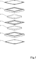
本発明による燃料電池構造の好適な実施例を、図1および図2に示す。燃料電池は、導電性陰極板1を含む。陰極封止枠2は、双極板1に隣接して設けられる。この枠は、陰極ガス分配層3のため、中央に長方形の開口を備える。枠2は陰極ガス入口9および出口10をも備え、分配流路は水入口および出口11、12にもそれぞれ形成される。陰極ガス分配層3は、陰極板1に関して層3の反対側に、複数の狭い水の流路3aを備える。プロトン交換膜4は、板1と協働するため、板1とプロトン交換膜4との間に枠2および拡散層3を挟み込むように配置される。
【0015】
燃料電池の陽極側は、陰極側と同様に構成される。従って、プロトン交換膜4の反対側は、導電性陽極板7と協働するため、導電性陽極板7とプロトン交換膜4との間に封止枠6および陽極拡散層5を挟み込むように配置される。陽極拡散層5は、陰極拡散層3と異なり、水の流路を持たない。陽極封止枠6は、陽極ガス入口13および出口14を備える。
【0016】
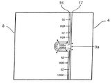
図2において、水の流路の詳細な構造および積層構造における水の分配する方法が示される。図の左手側は上面側を示し、図の右手側は下面側を示す。
【0017】
積層構造中の各封止枠2は、多数の貫通孔を有する。四隅に位置する穴は、多数のセルユニットをセル積層構造に組み上げるときに用いられる締付ボルト用である。他の穴は、積層構造の他の構成部品の対応する穴とともに、それぞれ積層構造中を流れる水、燃料ガス、および酸化剤ガスの流路を形成する。
【0018】
さらに、封止2の上側(先に定義したように)は、枠のような構造の内部端に沿って走るガス流路15を有する。多数の分配用開口(図中では5個)が、流入するガスを枠内に設置された拡散/分配材料中に分配するように、各流路15から流れをそらしている。穴の上面配置において(図中で)左から2つ目の穴は、流入するガス用の入口流路9であり、穴の下面配置において左から2つ目の穴は、陰極側でセルから流出するガス用の出口流路10である。陰極封止2は、積層構造中の位置に関係なく同じガス流路の構成を有する。
【0019】
各封止2の下面側(先に定義したように)では、共通の水入口11および共通の水出口12を有する水用の流路が設けられる。
【0020】
積層構造の中央には、積層構造の陰極および陽極部分を分離するように、膜4が配置される。陽極側では、陽極ガス分配層5が設けられ、その後、陰極封止2と同様に、陽極ガス入口および出口13、14が形成されている陽極用封止6が配置される。
【0021】
図3は、ガス分配層のより詳細な構造を示す。層3は、膜4に隣接する水の流路3aを備える。本発明の代表的な実施例においては、水の流路3aは、幅が約50〜100μmで、深さが約100〜300μmであり、各流路は約200〜1000μmの間隔で分離されている。水の流路を狭くすることにより、膜の膨張による流路の詰りを防止する。水の流路3aを作ることができる1つの方法は、所望の水の流路構造に対応する突条の構造表面を有する型板にガス分配層を押圧することである。
【0022】
図4は、ガス分配層3は触媒層16を有する本発明の実施例を示す。水の流路を一列に並べるように、無孔あるいはほぼ無孔のプロトン導電高分子層17が配置される。
【0023】
この実施例では、陰極側でセルに送り込まれる過酸化水素あるいは他の酸素放出化合物が、給湿および水冷却に追加される。酸素は触媒の近傍で放出されるため、効果的かつ酸素の消費が減るように陰極触媒でのCO吸着が防止される。過酸化水素の一部は、電極表面で分解して、H2O2 −>H2O+1/2O2の反応により酸素を発生する。このシステムでは、分解が完全に起こらなくても、過酸化水素の可能な利益が達成される。過酸化水素および放出された酸素の通路は、図4中に矢印で標記されている。しかしながら、この方法は、固体高分子型燃料電池の他の直接水給湿システムに適用することができる。
【0024】
図5は、その縁部に疎水性高分子処理を施して水がセルのガスチャンバーに進入するのを防止する、ガス分配層3を示す。この構造においては、双極板1、7中に、またはガス分配層3,5中にガス流路がない。ガス分配層は90%を超える多孔率を有することができ、電気良導体であり、酸性のプロトン導電膜に対して適当な耐食性を有するものとする。
【0025】
本発明は、従来の蛇行する流路構造と組合せてもよい。この原理を図6に示す。図2の実施例と同一の符号番号を用いた。各双極板1、7の陰極層側は、陰極ガス流路19および少なくとも1つの水入口20を有してもよい。水出口21を設けてもよい。各双極板の陽極層側は、少なくとも1つの陽極ガス流路22を有する。
【0026】
水流路用の代わりの構造を図7に示す。本発明のこの実施例において、触媒層16は膜4の上端に設置される。疎水性物質層18は、膜とガス分配層との間に位置する。この膜18の機能は、ガスを電極(触媒層)に拡散させ、かつ水を拡散させずに水の流路3aから逃がすことである。
【0027】
図7による実施例は、直接メタノール型燃料電池の動作に用いてもよい。本発明のこのような実施例において、セルの陰極側には、セル中で全体的にあるいは部分的に蒸発する液状の水‐メタノール混合物が送り込まれる。陰極電極のほとんどの部分が液状の水‐メタノール混合物の薄膜と接触することにより、液状の混合物が供給される。陰極電極の残りの領域は、液体から分離した気相と接触している。これにより、陰極電極の残りの領域へ気体の二酸化炭素の放出を加速し、しかも水蒸気反応物による膜の給湿が順に可能になる。水およびメタノールは、燃料供給流路から陰極電極へ直接または気相を経由して移送される。これを図7中に矢印により示す。上記の方法は、直接液体冷却式である他の型の燃料電池構造にも適用してもよい。
【0028】
水の流路構造は、好適には陰極側に適用される。しかし、この構造は陽極側にも、あるいは同時に両極にも適用可能である。
【0029】
本発明は、上記実施例に限定されるものではなく、上記実施例に代わるいくつかの改良が次の特許請求の範囲内で可能である。
【図面の簡単な説明】
【図1】 本発明に関する固体高分子型燃料電池構造の要素を示す斜視分解図である。
【図2】 図1中の構造のすべての要素について、上方および下方から見た平面図である。
【図3】 図1および2の構造に含まれるガス分配層の拡大断面図である。
【図4】 ガス分配層の第2実施例を示す。
【図5】 ガス分配層の第3実施例を示す。
【図6】 図2と同様な方法で、代わりの構造配置を示す。
【図7】 ガス分配層の更に別の実施例を示す。[0001]
(Technical field)
The present invention relates generally to fuel cells, and more particularly to improving the performance of solid polymer fuel cells.
[0002]
(Background of the Invention)
Solid polymer fuel cells are the edge of commercialization. Advances in catalyst and membrane research over the past few years have allowed fuel cells to obtain very high power densities (> 1 W / cm 2 ) with moderate efficiency (40%). The electrode catalyst loading was reduced to 0.1 mg Pt / cm 2 while maintaining high performance. Although other proton conductive film candidates have been discovered, the price of a perfluorinated sulfonic acid film such as Nafion (registered trademark) is expected to decrease as the production volume increases.
[0003]
However, as the scale of this polymer electrolyte fuel cell technology expands to large cells and stacked configurations, various serious problems are encountered. Since the proton conductive film must continue to be sufficiently humidified in the operating state, one of the main problems in stacking the polymer electrolyte fuel cell itself is water management.
[0004]
The dominant factor of the internal resistance loss in the laminated structure is that the proton conductivity of the membrane is limited. Proton migration draws water molecules from the cathode, so the membrane tends to dry particularly at the cathode side at high current densities.
The drying of the cathode affects not only the resistance but also the kinetics of the hydrogen reduction reaction (HRR).
[0005]
Therefore, to remedy this problem, the cathode side is often humidified more intensely than the anode side. The anode side of the cell can also be pressurized to use a pressure gradient across the membrane to push water back to the cathode side. However, it is important that water management does not interfere with the gas flow inside the cell.
[0006]
One solution to this problem would be to use a thin membrane, but this method is limited because the mechanical stiffness of the membrane must be sufficient.
[0007]
Another solution is to bring water into direct contact with the membrane on the cathode side because the moisture content and conductivity of the membrane is very high when the membrane is in equilibrium with water. Also, when the liquid evaporates inside the fuel cell, a significant amount (40-50%) of the heat can be removed from the cell along with the generated water vapor.
[0008]
US Pat. No. 5,958,613 (Hamada et al) relates to direct water humidification of such fuel cell membranes. There, the solid polymer type having the characteristic of humidifying the solid polymer film, which cools the battery body without providing a special humidifier for humidifying the fuel gas or oxidant gas and without providing a cooling channel A fuel cell system is disclosed. This patent does not disclose a specific operating principle for stacking fuel cells when direct humidification is applied.
[0009]
US Pat. No. 5,935,726 (Chow et al) describes a method and apparatus for improving the humidification of a polymer electrolyte fuel cell membrane by periodically reversing the oxidant flow through the fuel cell flow field. Is disclosed. However, this patent does not mention cooling of the fuel cell.
[0010]
(Summary of the Invention)
Despite various attempts to improve water management in polymer electrolyte fuel cells, there is room for further improvement.
[0011]
Therefore, an object of the present invention is to provide a means for improving the moisture supply property at low cost and with a simple battery structure. The trade-off between performance and cost should be acceptable.
[0012]
In the cell structure of the present invention, an aqueous phase , preferably water, is used for direct humidification of the membrane. The polymer electrolyte fuel cell structure according to the present invention includes a proton exchange membrane, a cathode catalyst layer on one side of the proton exchange membrane, an anode catalyst layer on the opposite side of the proton exchange membrane from the cathode catalyst, and gas distribution on both sides of the proton exchange membrane. Composed of layers. The cathode side gas distribution layer is a flat porous structure having a water flow path formed on the surface facing the membrane, and the cathode side gas distribution layer is connected to the water flow path in the gas distribution layer. It is sealed by a sealing plate in the same plane as the water inlet channel.
[0013]
Thereby, it is possible to keep the direct contact between water and the membrane on the cathode side. This is very beneficial for cell operation because the moisture content and conductivity of the membrane is very high when the membrane is in equilibrium with water. Also, when water evaporates inside the fuel cell, a significant amount of heat can be removed from the cell along with the generated water vapor.
[0014]
(Detailed description of the invention)
In the following, the invention will be further described without limitation with reference to the accompanying drawings.
A preferred embodiment of a fuel cell structure according to the present invention is shown in FIGS. The fuel cell includes a
[0015]
The anode side of the fuel cell is configured similarly to the cathode side. Accordingly, the opposite side of the proton exchange membrane 4, in order to work
[0016]
In FIG. 2, the detailed structure of the water flow path and the method of distributing water in the laminated structure are shown. The left hand side of the figure shows the upper surface side, and the right hand side of the figure shows the lower surface side.
[0017]
Each sealing
[0018]
Furthermore, the upper side of the seal 2 (as defined above) has a
[0019]
On the lower surface side of each seal 2 (as defined above), a water flow path having a common water inlet 11 and a
[0020]
In the center of the laminated structure, a film 4 is disposed so as to separate the cathode and anode portions of the laminated structure. In the anode side, an anode gas distribution layer 5 is provided, then, as a cathode sealing 2,
[0021]
FIG. 3 shows a more detailed structure of the gas distribution layer.
[0022]
FIG. 4 shows an embodiment of the invention in which the
[0023]
In this embodiment, hydrogen peroxide or other oxygen releasing compound that is fed into the cell on the cathode side is added to the humidification and water cooling. Since oxygen is released in the vicinity of the catalyst, CO adsorption on the cathode catalyst is prevented to be effective and reduce oxygen consumption. A part of the hydrogen peroxide is decomposed on the electrode surface and generates oxygen by a reaction of H 2 O 2 − > H 2 O + 1 / 2O 2 . In this system, the possible benefits of hydrogen peroxide are achieved without complete degradation. The passage of hydrogen peroxide and released oxygen is marked by arrows in FIG. However, this method can be applied to other direct water humidification systems of polymer electrolyte fuel cells.
[0024]
FIG. 5 shows a
[0025]
The present invention may be combined with a conventional meandering channel structure. This principle is shown in FIG. The same reference numbers as in the embodiment of FIG. 2 were used. The cathode layer side of each
[0026]
An alternative structure for the water channel is shown in FIG. In this embodiment of the invention, the
[0027]
The embodiment according to FIG. 7 may be used for the operation of a direct methanol fuel cell. In such an embodiment of the invention, the cathode side of the cell is fed with a liquid water-methanol mixture that evaporates in whole or in part in the cell. The liquid mixture is supplied by contacting most of the cathode electrode with a thin film of liquid water-methanol mixture. The remaining area of the cathode electrode is in contact with the gas phase separated from the liquid. This accelerates the release of gaseous carbon dioxide to the remaining area of the cathode electrode, and in turn allows the film to be humidified by the water vapor reactant. Water and methanol are transferred from the fuel supply channel to the cathode electrode directly or via the gas phase. This is indicated by arrows in FIG. The above method may also be applied to other types of fuel cell structures that are direct liquid cooled.
[0028]
The water channel structure is preferably applied to the cathode side. However, this structure can be applied to the anode side or simultaneously to both electrodes.
[0029]
The present invention is not limited to the embodiments described above, and several modifications in place of the embodiments described above are possible within the scope of the following claims.
[Brief description of the drawings]
FIG. 1 is an exploded perspective view showing elements of a polymer electrolyte fuel cell structure according to the present invention.
FIG. 2 is a plan view of all elements of the structure in FIG. 1 as viewed from above and below.
3 is an enlarged cross-sectional view of a gas distribution layer included in the structure of FIGS. 1 and 2. FIG.
FIG. 4 shows a second embodiment of the gas distribution layer.
FIG. 5 shows a third embodiment of the gas distribution layer.
6 shows an alternative structural arrangement in a manner similar to FIG.
FIG. 7 shows yet another embodiment of the gas distribution layer.
Claims (18)
Applications Claiming Priority (3)
| Application Number | Priority Date | Filing Date | Title |
|---|---|---|---|
| SE0002601-3 | 2000-07-07 | ||
| SE0002601A SE518621C2 (en) | 2000-07-07 | 2000-07-07 | Structure of a polymer fuel cell |
| PCT/SE2001/001514 WO2002005373A1 (en) | 2000-07-07 | 2001-06-29 | Polymer fuel cell structure |
Publications (3)
| Publication Number | Publication Date |
|---|---|
| JP2004503068A JP2004503068A (en) | 2004-01-29 |
| JP2004503068A5 JP2004503068A5 (en) | 2005-02-03 |
| JP5111714B2 true JP5111714B2 (en) | 2013-01-09 |
Family
ID=20280439
Family Applications (1)
| Application Number | Title | Priority Date | Filing Date |
|---|---|---|---|
| JP2002509127A Expired - Lifetime JP5111714B2 (en) | 2000-07-07 | 2001-06-29 | Solid polymer fuel cell structure |
Country Status (8)
| Country | Link |
|---|---|
| US (1) | US7790330B2 (en) |
| EP (1) | EP1301956B1 (en) |
| JP (1) | JP5111714B2 (en) |
| CN (1) | CN1235305C (en) |
| AU (1) | AU2001267984A1 (en) |
| CA (1) | CA2412180C (en) |
| SE (1) | SE518621C2 (en) |
| WO (1) | WO2002005373A1 (en) |
Families Citing this family (14)
| Publication number | Priority date | Publication date | Assignee | Title |
|---|---|---|---|---|
| US6566004B1 (en) | 2000-08-31 | 2003-05-20 | General Motors Corporation | Fuel cell with variable porosity gas distribution layers |
| US7592089B2 (en) | 2000-08-31 | 2009-09-22 | Gm Global Technology Operations, Inc. | Fuel cell with variable porosity gas distribution layers |
| US6663994B1 (en) | 2000-10-23 | 2003-12-16 | General Motors Corporation | Fuel cell with convoluted MEA |
| GB2390738B (en) * | 2002-07-09 | 2005-05-11 | Intelligent Energy Ltd | Fuel cell direct water injection |
| US6838202B2 (en) | 2002-08-19 | 2005-01-04 | General Motors Corporation | Fuel cell bipolar plate having a conductive foam as a coolant layer |
| KR100519767B1 (en) * | 2003-04-11 | 2005-10-10 | 삼성에스디아이 주식회사 | Fuel amount control system comprising pressure sensor |
| US20050221144A1 (en) * | 2004-03-30 | 2005-10-06 | Nissan Technical Center N.A. Inc. | Fuel cell apparatus |
| US20090169938A1 (en) * | 2004-03-30 | 2009-07-02 | Nissan Motor Co., Ltd. | Fuel cell apparatus |
| NL1026861C2 (en) * | 2004-08-18 | 2006-02-24 | Stichting Energie | SOFC stack concept. |
| US7601450B2 (en) * | 2005-03-23 | 2009-10-13 | Delphi Technologies, Inc. | Hybrid interconnect for a solid-oxide fuel cell stack |
| JP2007250351A (en) * | 2006-03-16 | 2007-09-27 | Toyota Motor Corp | Fuel cell |
| US7955753B2 (en) * | 2007-02-06 | 2011-06-07 | Nuvera Fuel Cells Europe S.R.L. | Bipolar unit for fuel cell provided with porous current collectors |
| CN102903938A (en) * | 2012-10-18 | 2013-01-30 | 西安交通大学 | Polymer fiber film methanol fuel cell with cathode adopting non-noble metal catalyst and preparation method thereof |
| JP2016091995A (en) * | 2014-10-30 | 2016-05-23 | 株式会社デンソー | Lithium air battery and lithium air battery device |
Family Cites Families (10)
| Publication number | Priority date | Publication date | Assignee | Title |
|---|---|---|---|---|
| JPH05144444A (en) * | 1991-11-25 | 1993-06-11 | Toshiba Corp | Fuel cell and electrode manufacturing method |
| JPH06338338A (en) * | 1993-05-28 | 1994-12-06 | Mitsubishi Heavy Ind Ltd | Humidification of high polymer ion exchange film of fuel cell |
| JP3203150B2 (en) * | 1995-05-18 | 2001-08-27 | 三洋電機株式会社 | Polymer electrolyte fuel cell and polymer electrolyte fuel cell system |
| US5879826A (en) * | 1995-07-05 | 1999-03-09 | Humboldt State University Foundation | Proton exchange membrane fuel cell |
| EP0996988A1 (en) * | 1997-05-13 | 2000-05-03 | Loughborough University Innovations Limited | Current distributors of sintered metals and fuel cells using them |
| US5935726A (en) * | 1997-12-01 | 1999-08-10 | Ballard Power Systems Inc. | Method and apparatus for distributing water to an ion-exchange membrane in a fuel cell |
| US6007933A (en) * | 1998-04-27 | 1999-12-28 | Plug Power, L.L.C. | Fuel cell assembly unit for promoting fluid service and electrical conductivity |
| CA2277405A1 (en) * | 1998-07-21 | 2000-01-21 | Matsushita Electric Industrial Co., Ltd. | Fuel cells stack |
| JP3022528B1 (en) * | 1998-11-30 | 2000-03-21 | 三洋電機株式会社 | Polymer electrolyte fuel cell |
| US6586128B1 (en) * | 2000-05-09 | 2003-07-01 | Ballard Power Systems, Inc. | Differential pressure fluid flow fields for fuel cells |
-
2000
- 2000-07-07 SE SE0002601A patent/SE518621C2/en not_active IP Right Cessation
-
2001
- 2001-06-29 JP JP2002509127A patent/JP5111714B2/en not_active Expired - Lifetime
- 2001-06-29 CN CNB018113664A patent/CN1235305C/en not_active Expired - Lifetime
- 2001-06-29 CA CA2412180A patent/CA2412180C/en not_active Expired - Lifetime
- 2001-06-29 WO PCT/SE2001/001514 patent/WO2002005373A1/en active Application Filing
- 2001-06-29 EP EP01945875A patent/EP1301956B1/en not_active Expired - Lifetime
- 2001-06-29 AU AU2001267984A patent/AU2001267984A1/en not_active Abandoned
-
2003
- 2003-01-07 US US10/248,304 patent/US7790330B2/en not_active Expired - Lifetime
Also Published As
| Publication number | Publication date |
|---|---|
| JP2004503068A (en) | 2004-01-29 |
| SE0002601L (en) | 2002-01-08 |
| US20030091887A1 (en) | 2003-05-15 |
| CA2412180C (en) | 2011-02-01 |
| SE0002601D0 (en) | 2000-07-07 |
| SE518621C2 (en) | 2002-10-29 |
| EP1301956A1 (en) | 2003-04-16 |
| EP1301956B1 (en) | 2012-08-01 |
| CA2412180A1 (en) | 2002-01-17 |
| US7790330B2 (en) | 2010-09-07 |
| CN1437776A (en) | 2003-08-20 |
| AU2001267984A1 (en) | 2002-01-21 |
| CN1235305C (en) | 2006-01-04 |
| WO2002005373A1 (en) | 2002-01-17 |
Similar Documents
| Publication | Publication Date | Title |
|---|---|---|
| US5382478A (en) | Electrochemical fuel cell stack with humidification section located upstream from the electrochemically active section | |
| CA2490877C (en) | Humidity controlled solid polymer electrolyte fuel cell assembly | |
| US5773160A (en) | Electrochemical fuel cell stack with concurrent flow of coolant and oxidant streams and countercurrent flow of fuel and oxidant streams | |
| JP4233208B2 (en) | Fuel cell | |
| JP5111714B2 (en) | Solid polymer fuel cell structure | |
| JP2002525824A (en) | Self-humidifying fuel cell | |
| JP4405097B2 (en) | Fuel cell stack and operation method thereof | |
| US10026977B2 (en) | Humidification device for humidifying process gases and fuel cell arrangement comprising same | |
| JP4232137B2 (en) | Fuel cell | |
| CA2616650C (en) | Modified fuel cells with internal humidification and/or temperature control systems | |
| CA2403156C (en) | A fuel cell stack and a method of supplying reactant gases to the fuel cell stack | |
| JP2000277128A (en) | Solid polymer type fuel cell | |
| JPH05144451A (en) | Reaction gas/cooling medium flowing structure of fuel cell with solid highpolymer electrolyte | |
| JP4031952B2 (en) | Fuel cell | |
| JP2001135326A (en) | Solid high molecular electrolyte fuel cell and stack of the same | |
| JP4642975B2 (en) | Polymer electrolyte fuel cell system | |
| JP2000251901A (en) | Cell for fuel cell and fuel cell using it | |
| JPH1173979A (en) | Solid polymer electrolyte fuel cell | |
| JPH06267562A (en) | Solid high polymer electrolyte fuel cell | |
| JP2003249243A (en) | Fuel cell | |
| JPH11111311A (en) | Solid polymer type fuel cell | |
| JP2003187838A (en) | Fuel cell stack | |
| JP2000251910A (en) | Solid high polymer electrolyte fuel cell | |
| JP2011222508A (en) | Moisture exchange unit and fuel cell stack | |
| JP2002042833A (en) | Solid polymer electrolyte type fuel cell |
Legal Events
| Date | Code | Title | Description |
|---|---|---|---|
| A621 | Written request for application examination |
Free format text: JAPANESE INTERMEDIATE CODE: A621 Effective date: 20080424 |
|
| A711 | Notification of change in applicant |
Free format text: JAPANESE INTERMEDIATE CODE: A711 Effective date: 20101001 |
|
| A521 | Request for written amendment filed |
Free format text: JAPANESE INTERMEDIATE CODE: A821 Effective date: 20101001 |
|
| A131 | Notification of reasons for refusal |
Free format text: JAPANESE INTERMEDIATE CODE: A131 Effective date: 20110913 |
|
| A601 | Written request for extension of time |
Free format text: JAPANESE INTERMEDIATE CODE: A601 Effective date: 20111212 |
|
| A602 | Written permission of extension of time |
Free format text: JAPANESE INTERMEDIATE CODE: A602 Effective date: 20111219 |
|
| A601 | Written request for extension of time |
Free format text: JAPANESE INTERMEDIATE CODE: A601 Effective date: 20120113 |
|
| A602 | Written permission of extension of time |
Free format text: JAPANESE INTERMEDIATE CODE: A602 Effective date: 20120120 |
|
| A601 | Written request for extension of time |
Free format text: JAPANESE INTERMEDIATE CODE: A601 Effective date: 20120210 |
|
| A602 | Written permission of extension of time |
Free format text: JAPANESE INTERMEDIATE CODE: A602 Effective date: 20120217 |
|
| A521 | Request for written amendment filed |
Free format text: JAPANESE INTERMEDIATE CODE: A523 Effective date: 20120223 |
|
| TRDD | Decision of grant or rejection written | ||
| A01 | Written decision to grant a patent or to grant a registration (utility model) |
Free format text: JAPANESE INTERMEDIATE CODE: A01 Effective date: 20121002 |
|
| A01 | Written decision to grant a patent or to grant a registration (utility model) |
Free format text: JAPANESE INTERMEDIATE CODE: A01 |
|
| A61 | First payment of annual fees (during grant procedure) |
Free format text: JAPANESE INTERMEDIATE CODE: A61 Effective date: 20121010 |
|
| FPAY | Renewal fee payment (event date is renewal date of database) |
Free format text: PAYMENT UNTIL: 20151019 Year of fee payment: 3 |
|
| R150 | Certificate of patent or registration of utility model |
Ref document number: 5111714 Country of ref document: JP Free format text: JAPANESE INTERMEDIATE CODE: R150 Free format text: JAPANESE INTERMEDIATE CODE: R150 |
|
| R250 | Receipt of annual fees |
Free format text: JAPANESE INTERMEDIATE CODE: R250 |
|
| R250 | Receipt of annual fees |
Free format text: JAPANESE INTERMEDIATE CODE: R250 |
|
| R250 | Receipt of annual fees |
Free format text: JAPANESE INTERMEDIATE CODE: R250 |
|
| R250 | Receipt of annual fees |
Free format text: JAPANESE INTERMEDIATE CODE: R250 |
|
| R250 | Receipt of annual fees |
Free format text: JAPANESE INTERMEDIATE CODE: R250 |
|
| R250 | Receipt of annual fees |
Free format text: JAPANESE INTERMEDIATE CODE: R250 |
|
| EXPY | Cancellation because of completion of term |