JP5109035B2 - Coin feeding device - Google Patents
Coin feeding device Download PDFInfo
- Publication number
- JP5109035B2 JP5109035B2 JP2006297283A JP2006297283A JP5109035B2 JP 5109035 B2 JP5109035 B2 JP 5109035B2 JP 2006297283 A JP2006297283 A JP 2006297283A JP 2006297283 A JP2006297283 A JP 2006297283A JP 5109035 B2 JP5109035 B2 JP 5109035B2
- Authority
- JP
- Japan
- Prior art keywords
- coin
- rotating disk
- moving body
- coins
- circumferential direction
- Prior art date
- Legal status (The legal status is an assumption and is not a legal conclusion. Google has not performed a legal analysis and makes no representation as to the accuracy of the status listed.)
- Active
Links
Images


Classifications
-
- G—PHYSICS
- G07—CHECKING-DEVICES
- G07D—HANDLING OF COINS OR VALUABLE PAPERS, e.g. TESTING, SORTING BY DENOMINATIONS, COUNTING, DISPENSING, CHANGING OR DEPOSITING
- G07D9/00—Counting coins; Handling of coins not provided for in the other groups of this subclass
- G07D9/008—Feeding coins from bulk
-
- G—PHYSICS
- G07—CHECKING-DEVICES
- G07D—HANDLING OF COINS OR VALUABLE PAPERS, e.g. TESTING, SORTING BY DENOMINATIONS, COUNTING, DISPENSING, CHANGING OR DEPOSITING
- G07D3/00—Sorting a mixed bulk of coins into denominations
- G07D3/12—Sorting coins by means of stepped deflectors
- G07D3/128—Rotary devices
Description
本発明は、保留部に収容した多数のコインを回転ディスクによりその区分け凹部に一つずつ保持して、外周部のコイン受取部を介して送出口から、次工程部、例えばコイン識別装置等へ送り出すコイン送り出し装置に関する。特に遠心力で回転ディスクの外周部に沿い移行して送り出されるコインを、安定かつ確実に送り出すのに好適なコイン送り出し装置に関する。
なお、本明細書で使用する「コイン」は、通貨のコイン、トークン及びメダル等を含み、形状は円形、多角形を含んでいる。
The present invention holds a large number of coins accommodated in the holding part one by one in the sorting concave part by a rotating disk, and passes from the outlet through the coin receiving part on the outer peripheral part to the next process part, for example, a coin identifying device. The present invention relates to a coin feeding device. Especially coins fed out moves along the outer periphery of the rotating disk by centrifugal force, to a suitable coin feeding device for feeding stably and reliably.
The “coin” used in this specification includes currency coins, tokens, medals, and the like, and the shape includes a circle and a polygon.
コイン送り出し装置についての従来技術として、ホッパ内に回転ディスクが設けられ、該ディスクに設けられた爪でコインを一枚ずつ掻き出し上方へ移動し、頂部付近の出口で硬貨レールにて受け止め、このレールに沿って出口から硬貨メカニズムに導く硬貨処理装置が知られている。(例えば特許文献1参照) As a conventional technique for a coin feeding device, a rotating disk is provided in a hopper, and coins are scraped one by one by a claw provided on the disk, and are moved upward and received by a coin rail at an exit near the top. A coin processing device that leads from the outlet to the coin mechanism is known. (For example, see Patent Document 1)
このような従来技術において、コインが回転ディスクにより出口へと送り出し動作されているときに、ホッパにコインが供給投入等されたりした時に生じる装置自体の振動などで、コインが爪から脱落する場合がある。
特に小径で厚みの薄いコインほど脱落が起こり易い。このようなコインが爪で掻き出され送出動作中にあったのにも係わらず、コインの脱落があると折角の送出動作が無駄になって、コインの処理効率を低下させ好ましくない。
また回転ディスクによる正常なコイン送り出し時には、コインは回転ディスクの盤面上を周方向に移動しながら押し出され、かつスリット状の出口に平行に入り込み何ら問題は無い。ここでスリット状に形成された前記出口の高さおよび幅は、横向きのコインすなわち回転ディスクの上面に横たわったコインが一枚だけ通過できるように設定されている。
ところが、コイン送り出し中に装置の振動等でコインが回転ディスクの盤面から跳ね動いたりすると、そのコインは勢いでスリット状の出口に斜めに突き当ってしまうことがある。
すると斜めに出口に衝突したコインは、その反対側には送り動作している爪が押し当たっているので、結局、当該コインは出口と爪との間に挟まれて回転ディスクはロック状態となってしまう。
このような状況では、回転ディスクは回転を停止してしまう。回転停止は動作異常と検出されて制御部によって装置全体が運転停止となってしまい、復旧にはロックしているコインを除去するなどの面倒な作業が必要となる。従って、このような原因での異常停止が度々ある場合も、コイン送り出し装置の稼動率を落としてしまうといった問題があった。
さらに、回転ディスクによって、出口近くまで運ばれて来たコインが硬貨レールに乗り移るとき、コインが装置自体の振動等を受けて不安定に揺れ動きレールから脱落することがある。またホッパ内で高速に攪拌回転されているコイン自体の不規則な動きが原因となって、レールに乗らず脱落してしまうこともある。
さらに時には脱落しないで、レール部に引っ掛かった状態でコインが停留してしまうケースも起こり得る。
この場合には、受取部に送り渡したコインを送り出し用ホイールで送り出すものでは、停留しているコインのために、それに押し当たるホイールが回転できず、装置が運転停止となってしまう。
このような問題もあるため、回転ディスクが回転し爪などのコイン送り出し部材によりコインを捕捉し、出口へと送り出し動作している行程中においては、コインの脱落やロック状態などを起こさないように安定した状態で搬送させることが、コイン処理効率を高め、優れた性能のコイン送り出し装置を得るには重要となる。
In such a conventional technique, when the coin is being fed out to the outlet by the rotating disk, the coin may fall off the nail due to vibration of the device itself that occurs when the coin is supplied to the hopper. is there.
In particular, coins with smaller diameters and thinner thickness are more likely to drop out. Even if such a coin is scraped out by a nail and is in the sending operation, if the coin is dropped, the sending operation at the corner is wasted, which is not preferable because the processing efficiency of the coin is lowered.
When the coin is normally fed out by the rotating disk, the coin is pushed out while moving in the circumferential direction on the surface of the rotating disk and enters the slit-shaped outlet in parallel, and there is no problem. Here, the height and width of the exit formed in a slit shape are set so that only one coin that lies sideways, that is, a coin lying on the upper surface of the rotating disk , can pass through.
However, if the coin jumps from the surface of the rotating disk due to the vibration of the device during the coin feeding, the coin may strike the slit-shaped outlet diagonally.
Then, the coin that collided with the exit diagonally has a feeding claw pressed against the opposite side, so that the coin is sandwiched between the exit and the claw and the rotating disk is locked. End up.
In this situation, the rotating disk would stop rotating. The rotation stop is detected as an abnormal operation and the entire apparatus is stopped by the control unit, and the recovery requires troublesome work such as removing the locked coin. Therefore, even when there are frequent abnormal stops due to such a cause, there has been a problem that the operating rate of the coin feeding device is lowered.
Further, when the coins carried to the vicinity of the exit are transferred to the coin rail by the rotating disk, the coins may be unstablely shaken due to the vibration of the device itself and fall off the rail. In addition, the coins being agitated and rotated at high speed in the hopper may fall off without being on the rails due to irregular movement.
Furthermore, there may be a case where the coin stops without being dropped and caught on the rail portion.
In this case, those feeds with wheels for feeding the coins passed sent to receiving unit, for being cut stop coins can not rotate wheel pressed against it, the device becomes a shutdown.
Due to these problems, the coins are not dropped or locked during the process of rotating the rotating disk and catching the coins with a coin feeding member such as a claw and feeding them to the outlet. Conveying in a stable state is important for improving the coin processing efficiency and obtaining a coin feeding device with excellent performance.
本発明は上記の点に鑑み成されたもので、第1の目的は、回転ディスクによりコインが送り動作されているときは、コインを、より安定した状態に維持して搬送できるような手段を講じることによって、コインを効率良く処理することができるようにしたコイン送り出し装置を提供するものである。
また、第2の目的は、コインを安定姿勢で搬送させる手段が、簡易な構成でかつ安価に達成できるように図ったコイン送り出し装置を提供するものである。
The present invention has been made in view of the above points, and a first object is to provide means for maintaining and transporting a coin in a more stable state when the coin is fed by a rotating disk. The present invention is to provide a coin feeding device which can efficiently process coins by taking them.
The second object is to provide a coin feeding device in which the means for transporting coins in a stable posture can be achieved with a simple configuration and at a low cost.
この目的を達成するため、請求項1の発明にかかるコイン送り出し装置は次のように構成されている。
回転ディスクの上面に配置した区分け凹部が前記回転ディスクの上面側、及び、周面側に開放した略半円状であって、当該区分け凹部の一部にコイン押進部を有し、前記区分け凹部の一部を形成し、かつ、前記回転ディスクの所定位相において周方向に移動を開始した後、所定位相において待機位置に戻り動可能な移動体を設け、前記区分け凹部にコインを保持して一つずつ区分けした後、前記移動体により、前記保持したコインを回転ディスクの周面側の開放部から送り出し、当該送り出されたコインを前記回転ディスクに対し周方向に延在するナイフ状のコイン受取部に受け渡すようにしたコイン送り出し装置において、
前記回転ディスクの回転時に前記コインが前記移動体により前記回転ディスクの周方向に移動され、前記コイン受取部に乗ったとき該コインを前記回転ディスクの上面に向かって弾性的に押し付けるための押し付け部材が設けられていることを特徴とするコイン送り出し装置としたものである。
In order to achieve this object, the coin feeding device according to the first aspect of the present invention is configured as follows.
The partitioning concave portion arranged on the upper surface of the rotating disk has a substantially semicircular shape opened on the upper surface side and the peripheral surface side of the rotating disk, and has a coin pushing portion in a part of the partitioning recess, A moving body that forms a part of the recess and starts moving in the circumferential direction at a predetermined phase of the rotating disk and then returns to the standby position at the predetermined phase is provided, and a coin is held in the sorting recess. after one by one divided, said by the mobile, feeding the coins the holding from the open portion of the peripheral surface of the rotating disk, a knife-shaped coins circumferentially extending the fed coins to the rotary disk In the coin feeding device that is handed over to the receiving part ,
A pressing member for elastically pressing the coin toward the upper surface of the rotating disk when the coin is moved in the circumferential direction of the rotating disk by the moving body when the rotating disk rotates and gets on the coin receiving portion. The coin feeding device is characterized in that is provided.
この構成において、回転ディスクが回転すると、それに連動して移動体が作動し、コインを外に押し出すと共に、周方向を移動させながら出口である開口へと送り出す。
その際にコイン押し付け部によってコインは、回転ディスクの上面へ押し付けられている。コインは回転ディスクの上面に安定状態で横たわり移動体の上に安定して乗っている。よって移動体によるコインの送り出し動作中、そのコインは移動体から脱落するようなことはない。このため、移動体が一旦保持したコインは必ず開口へと送られるようになるので、無駄のない処理が行われコイン処理効率が向上する。動作の信頼性が高く、故障も極度に少なくなるコイン送り出し装置を提供することができる。
In this configuration, when the rotating disk rotates, the moving body operates in conjunction therewith to push out the coin and feed it to the opening which is the outlet while moving in the circumferential direction.
At that time, the coin is pressed against the upper surface of the rotating disk by the coin pressing portion. The coin lies stably on the upper surface of the rotating disk and rests on the moving body stably. Therefore, during the coin feeding operation by the moving body, the coin is not dropped from the moving body. For this reason, since the coin once held by the moving body is always sent to the opening, the processing without waste is performed and the coin processing efficiency is improved. It is possible to provide a coin feeding device with high operation reliability and extremely few failures.
本発明の第1の好ましい例である請求項2の発明は、回転ディスクの上面に配置した区分け凹部が前記回転ディスクの上面側、及び、周面側に開放した略半円状であって、当該区分け凹部の一部にコイン押進部を有し、前記区分け凹部の一部を形成し、かつ、前記回転ディスクの所定位相において周方向に移動を開始した後、所定位相において待機位置に戻り動可能な移動体を設け、前記区分け凹部にコインを保持して一つずつ区分けした後、前記移動体により、前記保持したコインを回転ディスクの周面側の開放部から送り出し、当該送り出されたコインを前記回転ディスクに対し周方向に延在するナイフ状のコイン受取部に受け渡すようにしたコイン送り出し装置において、前記回転ディスクの回転時に前記移動体により前記回転ディスクの周方向へ移動し出す時に前記移動体の先端に乗っているコインと接触し前記回転ディスクの上面に向かって弾性的に押し付けるための第1弾性押し付け部が設けられ、さらに、前記コインが前記移動体により前記回転ディスクの周方向に移動され、前記コイン受取部に乗ったとき該コインを前記回転ディスクの上面に向かって弾性的に押し付けるための第2押し付け部が設けられていることを特徴とするコイン送り出し装置である。
この構成によれば、移動体の初期動作のコインを区分け凹部から外に押し出すときには、第1押し付け部によってコインは、回転ディスクの上面に押し付け状態とされている。このため回転ディスクの上面に、より安定した状態で横たわっているので、コインが移動体から脱落する恐れは無くなり、コインを着実に押し出すことができる。
移動体の更なる作動で、コインをコイン受取部に送り渡す際にも、第2押し付け部によりコインはディスクの上面に押し付けられ姿勢的に安定しているので、コインがスムーズにコイン受取部へ乗り移るようになる。
また乗り移った後も、回転ディスクの上面に押し付けられた状態にあるので、コインは送り出し用の回転ホイールが到来するまで、安定した状態でコイン受取部に乗っている。このためコインはコイン送り出しホイールによって一個ずつ確実に送り出される。
特にコインがコイン受取部にずり落ちた状態で留まるような事態はなくなるので、従来のように停留したままのコインによって、コイン送り出しホイールが回転不能となって送り出し装置が故障するというようなトラブルは、未然に防止できる。よって故障が無く、コインを確実に送り出すことができるようになる。
The invention of claim 2, which is a first preferred example of the present invention, has a substantially semicircular shape in which the partitioning concave portions arranged on the upper surface of the rotating disk are open on the upper surface side and the peripheral surface side of the rotating disk, A coin pushing portion is formed in a part of the partitioning recess, and a part of the partitioning recess is formed, and after starting to move in the circumferential direction in a predetermined phase of the rotating disk, it returns to the standby position in the predetermined phase. After the movable body is provided, the coins are held in the sorting recesses and sorted one by one, the held coins are sent out from the opening on the peripheral surface side of the rotating disk by the moving body, In the coin feeding device in which a coin is transferred to a knife-shaped coin receiving portion extending in a circumferential direction with respect to the rotating disk, the rotating disk is rotated by the moving body when the rotating disk is rotated. A first elastic pressing portion for contacting the coin on the tip of the moving body and elastically pressing the coin toward the upper surface of the rotating disk when moving in the circumferential direction of the moving body; A second pressing portion is provided for elastically pressing the coin toward the upper surface of the rotating disk when the moving body moves in the circumferential direction of the rotating disk and gets on the coin receiving portion. Is a coin feeding device.
According to this configuration, when the coin in the initial operation of the moving body is separated and pushed out from the recessed portion, the coin is pressed against the upper surface of the rotating disk by the first pressing portion. For this reason, since it lies on the upper surface of the rotating disk in a more stable state, there is no possibility that the coin will fall off the moving body, and the coin can be pushed out steadily.
When the coin is transferred to the coin receiving part by the further operation of the moving body, the coin is pressed against the upper surface of the disk by the second pressing part and the posture is stable, so the coin smoothly moves to the coin receiving part . I will change.
Further, since the coin is still pressed against the upper surface of the rotating disk after the transfer, the coin is on the coin receiving portion in a stable state until the rotating wheel for delivery arrives. For this reason, the coins are surely sent out one by one by the coin delivery wheel.
In particular, there will be no situation where the coin stays in a state where it has slipped down to the coin receiving part , so there is no trouble that the coin delivery wheel becomes unable to rotate due to the coin that has been stopped as before and the delivery device fails. Can be prevented. Therefore, there is no failure and the coin can be sent out reliably.
本発明の第2の好ましい例である請求項3の発明は、回転ディスクの上面に配置した区分け凹部が前記回転ディスクの上面側、及び、周面側に開放した略半円状であって、当該区分け凹部の一部にコイン押進部を有し、前記区分け凹部の一部を形成し、かつ、前記回転ディスクの所定位相において周方向に移動を開始した後、所定位相において待機位置に戻り動可能な移動体を設け、前記区分け凹部にコインを保持して一つずつ区分けした後、前記移動体により、前記保持したコインを回転ディスクの周面側の開放部から送り出し、当該送り出されたコインを前記回転ディスクに対し周方向に延在するナイフ状のコイン受取部に受け渡すようにしたコイン送り出し装置において、前記回転ディスクの回転時に戦記移動体により前記回転ディスクの周方向へ移動し出す時に前記移動体の先端に乗っているコインと接触し前記回転ディスクの上面に向かって弾性的に押し付けるための第1弾性押し付け部が設けられ、さらに、前記コインが前記移動体により前記回転ディスクの周方向に移動され、前記コイン受取部に乗ったとき該コインを前記回転ディスクの上面に向かって弾性的に押し付けるための第2押し付け部が設けられ、前記第1押し付け部に連設形成された前記回転ディスクの回転方向上流側に向かって前記上面に対し上向きに傾斜し、前記第1押し付け部から前記回転ディスクの周縁まで延在する阻止板が形成されていることを特徴とするコイン送り出し装置としたものである。
この構成によれば、コイン送り動作中にコインが送り出し部である開口の周囲にあたるように動いても、開口の手前で上向きに傾斜している阻止板によってその移動が止められるので、開口の入り口の周囲にコインが衝突することは無くなる。
このため、従来のようなコインが開口の周囲に衝突し、移動体との間でコインが挟まりロック状態になってしまう事態の発生を防ぐことができる。
こうしてコインが送り出し中にロックし、そのため回転ディスクが回転できなくなるという故障は少なくなり、長期に亘って正常に運転される性能の高いコイン送り出し装置を得ることができる。
The invention of claim 3, which is a second preferred example of the present invention, has a substantially semicircular shape in which the partitioning concave portions arranged on the upper surface of the rotating disk are open on the upper surface side and the peripheral surface side of the rotating disk, A coin pushing portion is formed in a part of the partitioning recess, and a part of the partitioning recess is formed, and after starting to move in the circumferential direction in a predetermined phase of the rotating disk, it returns to the standby position in the predetermined phase. After the movable body is provided, the coins are held in the sorting recesses and sorted one by one, the held coins are sent out from the opening on the peripheral surface side of the rotating disk by the moving body, In the coin feeding device in which coins are transferred to a knife-shaped coin receiving portion extending in a circumferential direction with respect to the rotating disk, the rotating disk is rotated by a war record moving body when the rotating disk rotates. A first elastic pressing portion for contacting the coin on the tip of the moving body and elastically pressing the coin toward the upper surface of the rotating disk when moving in the circumferential direction of the moving body; A second pressing portion is provided for elastically pressing the coin toward the upper surface of the rotating disk when the moving body moves in the circumferential direction of the rotating disk and gets on the coin receiving portion. A blocking plate is formed which is inclined upward with respect to the upper surface toward the upstream side in the rotation direction of the rotating disk formed continuously with the portion and extends from the first pressing portion to the periphery of the rotating disk. A coin delivery device characterized by the above.
According to this configuration, even if the coin moves so as to hit the periphery of the opening which is the feeding portion during the coin feeding operation, the movement is stopped by the blocking plate inclined upward in front of the opening. Coins will no longer collide around.
For this reason, it is possible to prevent the occurrence of a situation in which a conventional coin collides with the periphery of the opening and the coin is pinched between the movable body and becomes locked.
Thus, the failure that the coins are locked during the feeding and the rotating disk cannot be rotated is reduced, and a coin feeding device having high performance that can be operated normally for a long time can be obtained.
本発明の第3の好ましい例は、請求項1又は第1若しくは第2の好ましい例において、前記押し付け部材は、前記開口の手前に位置して先端が回転ディスク上のコインと接触するように下向きに傾斜して伸びた第1弾性押し付け片と、前記開口の後ろ寄りに位置して先端が回転ディスク上のコインと接触するように下向きに傾斜して伸びた第2弾性押し付け片とが一体形成された弾性押付板であるコイン送り出し装置である。
この構成により、第1弾性押し付け片は、開口の手前寄りで、移動体がコインを区分け凹部の外に押し出すように作動するタイミングに合う場所にあるので、コインの効果的な押し出しが行える。また第2弾性押し付け片が開口の後ろ寄りで、移動体がコイン受取部に送り渡すように作動するタイミングに合わせた場所に設けてあるので、コインを効果的に開口に送り込むことができる。
また第1弾性押し付け片と第2弾性押し付け片とが開口の手前間位置と後ろ位置に一体に形成してある弾性押付板を用いることで、簡易な構成でもって、コインを安定して送り出しできる。さらに弾性押付け板を合成樹脂で作製することも可能なので、その場合には簡易でかつ安価な部材で提供できるようになり、実用性に富むものである。
According to a third preferred example of the present invention, in the first claim or the first or second preferred example, the pressing member is positioned in front of the opening so that the tip is in contact with the coin on the rotating disk. A first elastic pressing piece that is inclined and extended and a second elastic pressing piece that is located near the rear of the opening and extends downward and inclined so that the tip contacts the coin on the rotating disk are integrally formed. It is a coin delivery device which is an elastic pressing plate.
With this configuration, the first elastic pressing piece is located near the opening and in a position that matches the timing at which the moving body operates so as to sort and push the coin out of the recess, so that the coin can be effectively pushed out. In addition, since the second elastic pressing piece is provided behind the opening and at a position that matches the timing at which the moving body operates so as to deliver the coin to the coin receiving portion , the coin can be effectively fed into the opening.
Further, by using an elastic pressing plate in which the first elastic pressing piece and the second elastic pressing piece are integrally formed at the front position and the rear position of the opening, the coin can be stably fed out with a simple configuration. . Further, since the elastic pressing plate can be made of a synthetic resin, in that case, it can be provided with a simple and inexpensive member, which is practical.
回転ディスクの上面に配置した区分け凹部にコインを保持して一ずつ区分けした後、前記区分け凹部に可動自在に設けたコイン押し出し用の移動体により、コインを回転ディスクの周方向の所定位置に設けたコイン受取部を備える開口から送り出すようにしたコイン送り出し装置において、前記回転ディスクによりコインが前記区分け凹部から外へ押し出され前記開口へと運ばれる際に、コインを回転ディスクの上面に弾性的に押し付けるための押し付け部材を設けることにより、コインが安定した姿勢でディスクの上面を移動するようになるため、コイン処理を安定してかつ正確に行うことができる。 After holding the coins in the partitioning recesses arranged on the upper surface of the rotating disk and sorting them one by one, the coins are provided at predetermined positions in the circumferential direction of the rotating disk by a moving body for pushing the coins movably provided in the partitioning recesses. In the coin delivery device configured to deliver from the opening provided with the coin receiving portion , when the coin is pushed out of the sorting recess by the rotating disk and carried to the opening, the coin is elastically applied to the upper surface of the rotating disk. By providing the pressing member for pressing, the coin moves on the upper surface of the disk in a stable posture, so that the coin processing can be performed stably and accurately.
以下、本発明の実施例を図面に基づいて説明する。
図1は、本発明の実施例に係るコイン送り出し装置を使用したコイン処理装置の概略正面図である。図2は、本発明の実施例に係るコイン送り出し装置の正面図である。図3は、本発明のコイン送り出し装置に設けられるコイン押し付け部材の正面図である。図4は押し付け部材の下面図である。図5乃至図10は、本発明の実施例のコイン送り出し装置の作用を示す具体例で、図5は本発明の実施例のコイン送り出し装置によりコインの脱落が解消されることを示す正面図、図6はその外観斜視図である。図7と図8は、本発明の実施例のコイン送り出し装置によりコインの受け取りミスが解消されることを示す正面図とその外観斜視図である。図9と図10は、同様に本発明の実施例のコイン送り出し装置により、開口(コイン送り出し口)でのコインのロック状態が解消されることを示す正面図とその外観斜視図である。
図11は、本発明のコイン送り出し装置の構造を概略的に示した全体外観斜視図である。図12乃至図15は、本発明の改良前のコイン送り出し装置によるコイン送り出し時の様々な不具合を示す図で、図12は、コインの脱落現象を示す正面図である。図13は、コインの受け取りミスの現象を示す正面図である。図14は、コインがロックし一時止まりするときの現象を示す正面図であり、図15は同図におけるA−A線断面図である。
Embodiments of the present invention will be described below with reference to the drawings.
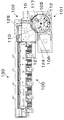
FIG. 1 is a schematic front view of a coin processing apparatus using a coin feeding apparatus according to an embodiment of the present invention. FIG. 2 is a front view of the coin dispensing apparatus according to the embodiment of the present invention. FIG. 3 is a front view of a coin pressing member provided in the coin feeding device of the present invention. FIG. 4 is a bottom view of the pressing member. 5 to 10 are specific examples showing the operation of the coin feeding device according to the embodiment of the present invention, and FIG. 5 is a front view showing that coin dropping is eliminated by the coin feeding device according to the embodiment of the present invention. FIG. 6 is an external perspective view thereof. 7 and 8 are a front view and an external perspective view showing that a coin receiving error is eliminated by the coin feeding device of the embodiment of the present invention. FIG. 9 and FIG. 10 are a front view and an external perspective view showing that the coin lock state at the opening (coin delivery port) is canceled by the coin delivery device of the embodiment of the present invention.
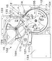
FIG. 11 is an overall external perspective view schematically showing the structure of the coin delivery device of the present invention. 12 to 15 are diagrams showing various problems during coin feeding by the coin feeding device before improvement of the present invention, and FIG. 12 is a front view showing a coin dropping phenomenon. FIG. 13 is a front view showing a phenomenon of coin receiving mistake. FIG. 14 is a front view showing a phenomenon when the coin is locked and temporarily stopped, and FIG. 15 is a cross-sectional view taken along line AA in FIG.
先ず、図1乃至図11に基づき、本発明のコイン送り出し装置の構造を説明する。
本実施例は、ヨーロッパ共同体の通貨である2ユーロ、1ユーロ、50セント、20セント、10セント、5セント、2セント及び1セントの8種類の硬貨を受け入れて金種毎に保留し、払出指示に基づいて所定金種の硬貨を所定数出金するコイン処理装置のコイン送り出し装置である。
図1においてコイン処理装置100は、コイン送り出し装置101と金種判別装置102とコイン搬送装置103と、このコイン搬送装置103の内部に設けた図示しないコイン選別装置とを含んでいる。
すなわちコイン送り出し装置100にはコインを一つずつ区分して送り出す回転ディスク105が設けられ、回転ディスク105にピボット運動可能に設けてある移動体117により、コインが一枚ずつ金種判別装置102へと送り出される。金種判別装置102へは、コイン送り出し装置101の上部位置に設けてあるコイン受け渡し用の開口106を通してコイン110が送り込まれる。
First, based on FIG. 1 thru | or FIG. 11, the structure of the coin delivery apparatus of this invention is demonstrated.
This example accepts 8 types of coins, 2 euros, 1 euro, 50 cents, 20 cents, 10 cents, 5 cents, 2 cents and 1 cent, which are the currencies of the European Community, and holds them for each denomination. A coin delivery device of a coin processing device that dispenses a predetermined number of coins of a predetermined denomination based on an instruction.
In FIG. 1, a
That is, the
本発明の特徴は、このコイン送り出し装置101の回転ディスク105の回転動作により、該ディスクの外周方向に押し出され、続いてディスクの外周部を移動しながら、前述の上部位置にある開口106へと送り出されて行くコイン110を、回転ディスク105の上面105Sに押し付ける押し付け部材10を具備させることによって、コイン送り出し動作が安定して行なわれるようにしたものである。
押し付け部材10は、開口106の周辺に回転ディスク105の回転経路に沿うように配設されている。これによってコイン110がコイン送り出し装置101から金種判別装置102へと送られる間、コインが移動体117から脱落することがなく、また移動経路の途中で詰まったりすることもなく、開口106に確実に送り込まれるようになるので、コインの処理を効率良く行うことができるようになる。その詳細については後述する。
A feature of the present invention is that the
The pressing
前記金種判別装置102内では図示しないが磁気センサーなどによって、コインの真偽並びに金種の判別が行われた後、次の行程の搬送装置103へと送られ、その所定経路を搬送する途中において所定のゲートが開閉するような機構のコイン選別装置で金種別に分離するようにしたものである。
コイン送り出し装置100について、さらに説明するとコイン送り出し装置100は、回転ディスク105、コイン保留のための保留ボウル104、及び保留ボウル104の下部に前記回転ディスク105を囲むように位置するシリンダ形の保留リング107を含んでいる。硬貨投入口から投入された複数金種のコインは、保留ボウル104の開放口からその下部の保留部に誘導落下し山積み状に保留される。
Although not shown in the
The
回転ディスク105は、コインを一つずつ受け入れる区分け凹部113を有し、所定の角度で前記保留リング107の底部に傾斜設置され、かつ所定の速度で一定方向に、実施例では矢印Gに示す反時計方向に回転される。
回転ディスク105は、ベースとなる回転円板111と、この回転円板111の上面に回転円板111と同心に固定され、かつ3つの凹部を突部115にてその間にほぼ等間隔に有するY字形のプレートよりなる押し出しディスク112とよりなり、この押し出しディスク112の突部115と突部115との間及び後述する移動体117とで、回転円板111の上面に略半円状の区分け凹部113が形成される。
また、区分け凹部113の深さ、換言すれば押し出しディスク112の厚みは、前記8金種のうち最も薄いコインの厚みよりも僅かに浅く形成されている。
なおプレートは、Y字形のものに限らず、複数の突部が放射状に形成された形態のプレートであってもよい。また、回転円板111とプレートすなわち押し出しディスク112は、焼結前記金属又は耐摩耗性を有する樹脂により一体成型することもできる。
The
The
Further, the depth of the
The plate is not limited to a Y shape, and may be a plate having a plurality of protrusions formed radially. Further, the
突部115間の区分け凹部113の一側には、ピボット軸120を支点としてピボット運動する移動体117が配置されている。
区分け凹部113は、この移動体117と突部115間の凹部とで回転円板111上にほぼ半円形状の区分け凹部として形成される。なお突部115においてその区分け凹部113の他方側には、僅かに窪んだ凹みが形成され、この凹みにてコイン110を受け入れかつ押し当てて運ぶように作用するコイン押進部121が形成されている。またこのコイン押進部121に対向して、移動体117を受けるための弧状の受け部118が区分け凹部113に設けられている。
ここで、区分け凹部113は、最小径コインが二つ並んで受け入れられることができず、かつ、最大径コインが一枚のみ受け入れられる大きさに設定されている。
したがって区分け凹部113には、最小径コインが回転ディスク105の直径方向に二枚並んで受け入れられることがない。
A
The
Here, the sorting
Therefore, two coins having the smallest diameter are not received in the
前記移動体117は、通常は区分け凹部113を形成するように凹部の一側に寄った位置に静止状態に位置し、ピボット運動して所定位置に移動した場合、保持されていたコイン110を回転円板111の周方向に送り出す。
移動体117のこの所定位置での移動は、保留リング107の上部において、金種判別装置102へとコインが通過できるように形成した前述のコイン受け渡し用の開口106より少し下流付近の回転ディスク105の回転経路で行われる。開口106を過ぎると、移動体117は凹部の一側に形成した受け部118に納まるように戻り動作される。
こうした移動体117の移動は、回転円板111の回転動作を利用して溝カムなどで行うことが可能である。すなわち、移動体117の中間にピン122を固定して設け、このピン122を回転ディスク105の回転円板111に形成した前記ピボット軸120を中心として形成した弧状の通孔123に挿入する。さらにこのピン122を図示しないが回転円板111の下側に設けた溝カムに、ローラー等の被動体を介して摺動自在に挿入させるという駆動機構を用いるようにすればよい。
また回転ディスク105は電気モータ124(図1参照)によって回転される。電気モータ124の回転は減速機を介して、図示はしていないが回転円板111の下部周面に形成された減速ギヤに伝達され、回転ディスク105は所定の速度で回転されるような駆動機構である。
The moving
The moving
Such movement of the moving
The
一方、コインが送入される金種判別装置102側には、コイン送り用のホイール128が設けられている。そしてホイール128と対応して金種判別装置102内にコインガイドレール129が設けられている。
さらにこのコインガイドレール129の開口106に近い部分は、コイン110を受け取り易いようにナイフ状のコイン受取部127(図5、6等参照)に形成されている。コインガイドレール129及びコイン受取部127の厚みは、コイン110に対して十分な厚みを持つものとされている。
On the other hand, a
Further, a portion of the
したがって、上述の構造の回転ディスク105によって、保留ボウル104内にあるバラ積みのコイン110が攪拌され、かつそのコイン110が、一つずつ区分け凹部113に保持され上方へ移動し、回転中心よりも上方の所定の位置に来た時点で移動体117により区分け凹部113から周方向へ押し出される。
押し出されたコイン110はコイン受取部127を経て開口106に至る。次いで開口106に臨むように回転している金種判別装置102側のホイール128の送り腕部128aにより、金種判別装置102内へガイドレール129を転動しながら送り込まれ、コイン110の金種判別が行われた後、搬送装置104へと送られる。
このようにコイン110は傾斜して設置した回転ディスク105と同じ傾斜姿勢で、回転ディスク105によって開口106から金種判別装置102側のコイン通路130に送り込まれ、コイン受取部127に受け取れられる。前記開口106は、図2、図11等から理解されるように、箱体状をした金種判別装置102の右下隅角部の斜めカット部に設けられている。
Accordingly, the
The pushed-out
In this manner, the
さらに金種判別装置102について説明すると、金種判別装置102は、円形状の凹所126に前記ホイール128を収容し、かつコインガイドレール129およびコイン受取部127等を装着した下側の平板状をした固定基板133と、該固定基板133に対し右側の取付軸135にて開閉可能に枢支され、かつ箱状のケースを有し、該ケース内に金種判別用のセンサー等を内蔵した本体部134とから成る。
ここで前記固定基板133に形成した円状凹所126は円周部の一部が開放され、コイン送り出し装置101の装置内凹所109と連通している(図5等参照)。
前記円状凹所126の内底面は、ホイール設置ベース面126Sであり、前記装置内凹所109の内底面は回転ディスクの上面105Sである。そしてホイール設置ベース面126Sと回転ディスクの上面105Sとは、面一の状態で連続している。よってコイン送り面である円状凹所126の内底面と装置内凹所109の内底面とが面一で平滑な面で連続しているので、コイン110がコイン送り出し装置101側から金種判別装置102側へと開口106を通してスムーズに移動可能となる。
Further, the
Here, the
The inner bottom surface of the
そして金種判別装置102の本体部134を閉じたとき、本体部134の裏面134Bは、図15に示すように、円状凹所126の内底面であるホイール設置ベース面126Sと向かい合い、かつ装置内凹所109の内底面である回転ディスクの上面105Sとも向かい合う。よって、それら3つの部材の間に開口106が形成される。
ここで前記開口106はスリット状であって、その厚みと幅は、送り出されるコイン110が一枚通過できる程度に設定されている。本コイン送り出し装置は複数の金種のコインが取り扱われるものなので、最大厚み、最大径のコインに可及的に合わせた厚みと幅に形成された開口106に設定されている。
また開口106は詳細には、上述の本体部の裏面134Bと円状凹所126と装置内凹所109の各内面などの他に、開口106の厚み幅を規定するコイン受取部127とこれと対向位置している円状凹所の右側突端部140(図6、9参照)との4つの部材により囲まれて形成された矩形状の開口口である。また、閉じた本体部の裏面134Bで、ホイール128の表面側は覆い隠されるようになる。
When the
Here, the
More specifically, the
ここで、開口106の部分には、図11に示すように横長板状の取付板8が、金種判別装置102の本体部134の下端部に庇状に装着されている。
この庇状の取付板8は、本体部134を閉じたときに、ホイール設置ベース面126Sおよび回転ディスクの盤面105Sと相対し、開口106の上面壁となって開口106の一部を構成するものとなっている。
Here, as shown in FIG. 11, a horizontally long mounting
The hook-shaped mounting
ところで回転ディスク105が回転し、それに連動してピボット作動する移動体117によってコイン110が区分け凹部113の外に押し出され、かつ保留ボウル104の内周面を移動しながら前記開口106に向けて送り出される時に、その送り動作がときには正常に行われないことがある。
例えば、図12に示すような現象である。
すなわち移動体117によってコイン110が区分け凹部113から押し出されるとき、装置の振動などでコイン110が移動体117の先端117eから脱落することがある。
コイン110が移動体117に捕捉され、開口106へと順調に送り出し態勢に入った途中で、コイン110が落下したりすることが頻繁にあると、コインの送給率が低下し、コイン処理能力が劣る装置となってしまう。
By the way, the
For example, the phenomenon shown in FIG.
That is, when the
If the
また図13に示すように、コイン110が移動体117によってコイン受取部127に乗る最終段階で、コイン受取部127から脱落したり、或いは落ち切らずにコイン受取部127の先端127eに引掛かった状態で留まることがある。
コイン110がコイン受取部127にきちんと乗らず、コイン受取部127に引掛かって留まっている場合は、ホイール128はこの止まっているコイン110のために回転できず、その腕128aでコイン110を送り出すことができない。ホイール128が回転不能となるので、運転異常と判断されて装置自体が運転停止となってしまう。
In addition, as shown in FIG. 13, at the final stage when the
さらに、図14および図15に示すように、区分け凹部113からコイン110が移動体117により外周へ移動されるときに、装置の振動等でコイン110が回転ディスク105の盤面から跳ね、かつあるコイン110は勢いで回転ディスク105の外側へ向かう。そしてそのコインが図15に示すコイン110Bのように開口106の入り口を構成する部材に衝突することがある。すなわちコイン110Bは斜めになって、取り付け板8の先端部8dに上端部110gが突き当たり開口106で止まってしまう。開口106の入り口で止まったコイン110Bには、その反対側に移動体117が押し当たっているので、結局、コイン110Bは開口106と移動体117との間に挟まってロックし動けなくなってしまう。
こうしてロックしたコイン110Bによって、回転ディスク105が回転できなくなり、装置が異常停止となってしまうのである。
運転停止となった装置の復旧には、止まったコイン110Bの除去などを必要とするので、結局、コイン処理装置の稼働率が落ちてしまうことになる。
Further, as shown in FIGS. 14 and 15, when the
The
Since the recovery of the apparatus that has been stopped requires the removal of the stopped
本発明はこのようなトラブルが起きないように改良したものである。
先ず、金種判別装置102の本体部134の下端には、前述したように庇状に延びた横長板状の取付板8が設けられている。
一方、図2乃至図10等に示すように、回転ディスク105の開口106に近い回転経路には、コイン110を回転ディスク105の上面105Sに弾性的に押し付けるための押付け部材10が配設されている。
コイン110はこの押し付け部材10によって、その押し付け面側と反対側の面、すなわちコイン110の下面が適度の押し付け力で回転ディスク105の上面105Sに押し付けられることとなる。このためコイン110は回転ディスク105の上面105Sに安定した状態で横たわるようになる。こうしてコイン110を安定した姿勢で、回転ディスク105の上面105Sに載せて置くことができるので、コイン110をスムーズに送り出せるようになる。
押し付け部材10は、合成樹脂などにより形成され、図3に示すような平面形状であって、かつその一部分に図4に示すように傾斜部12を有した構造になっている薄厚のフレキシブルな弾性板である。
押付け部材10は、前記取付板8の裏側に糊付け等にて装着される。糊付け部分を斜線22で図示してある。なお、該押付け部材10は、合成樹脂、例えば0.3mm厚のポリカーネイト材で形成することができる。
押付け部材10は、合成樹脂などフレキシブルな部材で形成されているので、それ自身が適度の弾性力を有するものとなっている。
The present invention has been improved so that such trouble does not occur.
First, at the lower end of the
On the other hand, as shown in FIG. 2 to FIG. 10 and the like, a pressing
The
The pressing
The pressing
Since the pressing
さらに詳述すると前記押付け部材10は、所要の幅、長さを有する板状の基部10kを有し、この板状の基部10kの一端側に所定の傾斜角度、例えば30度の傾斜角度で前述の傾斜部12が一体形成されている。
前記傾斜部12は、基部10kより下側に向かって伸びている第1押し付け部14を有する。該第1押し付け部14は、第1弾性押し付け片14Hなるものである。
また前記傾斜部12には、前記第1押し付け部14と同一面部で連設した、基部10kより上側に向かって伸びている阻止板15(後述する)が形成されている。前記阻止板15は、コイン110が開口106を構成する周囲の部材に当たる方向へ進行しないように阻止するためのものであるが、その点は後述する。
More specifically, the pressing
The
Further, the
また前記押付け部材10は、他端側に所定の傾斜角度、例えば30度の傾斜角度で曲げて設けた第2押し付け部16を備えている。前記第2押し付け部16は、第2弾性押し付け片16Hなるものである。
The pressing
ここで前記第1弾性押し付け片14Hは、その先端が図4に示すようにコイン110の上面に弾性的に接触するような構成となっている。
すなわち同図に示すように、第1弾性押し付け片14Hは、その先端がコインの厚みDよりも僅か低い位置になるような取り付け高さdで、回転ディスク105の上面105Sの上方に設けられている。
同様に第2弾性押し付け片16Hも、その先端がコインの厚みDよりも僅か低い位置になるような取り付け高さdで、回転ディスク105の上面105Sの上方に設けられている。
なお、この場合、複数の金種のコイン110を取り扱うので、前記取り付け高さdは、最も薄いコインの厚みDよりも低い位置に設定される。
よってこのような条件で第1、第2の弾性押し付け片14H,16Hが位置するように押付け部材10を設けてあるので、各弾性押し付け片14H,16Hは、夫々がコインで撓んだ先端の撓み量に応じた反発力でコイン110を回転ディスク105の上面105Sへ押し付けるようになる。
Here, the first elastic
That is, as shown in the figure, the first elastic
Similarly, the second elastic pressing
In this case, since a plurality of
Therefore, since the pressing
前記押付け部材10はその第1押付け部14(第1弾性押し付け14H)が開口106の手前寄りに位置するように設け、第2押し付け部16(第2弾性押し付け片16H)が開口106の後ろ寄りに位置するように設けてあり、第1,2の押し付け部14、16のそれぞれが移動体117で移動されるコイン110とタイミング良く接触するような個所にあるものとなっている。
よって、移動体117によりコイン110が外周側へ移動し出す時に、タイミング良く押付け部材10の第1弾性押し付け片14Hは、図5,6に示すように移動体117の先端に乗っているコイン110と接触し、これを押し付けるようになる。このためコイン110は、回転ディスク105の上面105S上に安定した状態で横たわり、移動体117によるコイン110の移動がスムーズに行われるようになる。
すなわち、コイン110が回転ディスク105の上面105Sから離れないように安定して押さえられようになるので、コイン110が移動体117の厚み方向に不安定に動くことは防止され、安定した状態で載る。移動体117がピボット動作してコイン110を区分け凹部113から押し出す最後の段階まで、コイン110を移動体117から脱落しないように保持することができるようになり、コイン110を確実に送り出すことができる。これによりコインの送給率が向上する。
The pressing
Therefore, when the
That is, since the
押し付け部材10による押し付け力は、押付け部材10の材質の選定、弾性押し付け片14H,16Hの傾斜角度、設置高さにより変更可能なのであり、それらを自在に設定することにより、必要とする適度の押し付け力を得ることができる。
実施例では第1弾性押し付け片14Hと第2弾性押し付け片16Hは、共に30度の傾斜角度としたが、異なる傾斜角度であってもよい。
なお第1押付け部14がコイン110を押さえる部分を、遠心力の作用が小さい部分である、コイン110の中心から下半分域のコイン面を押さえるようにする。この理由は回転ディスク105の回転中心より、より外周側の遠い位置であるコインの上半分域のコイン面を押さえるものだと、遠心力の影響でコインへの押圧力が不安定になり、移動体が安定してコインを保持することができないことが予測されるからである。
The pressing force by the pressing
In the embodiment, the first elastic
The portion where the first pressing
さて、コイン110がさらに運ばれ開口106に近づいたときには、押付け部材10の第2押し付け部16が作用する。次にこれについて説明する。
第2押し付け部16は、前記第1押し付け部12とは反対側の個所に、回転ディスク105の上面105Sに向かって下向きに傾斜させた折曲形成した三角形状の板状の曲げ部である。この曲げ部である第2弾性押し付け片16Hで、コイン110を下方にすなわち回転ディスクの上面105Sに向けて押し付けるようにしている。
第2押し付け部16は、図7、8に示されるように、コイン受取部127と対向して位置している。
したがって、回転ディスク105が回転し、移動体117のピボット動作でコイン110がコイン受取部127の上に乗ったとき、タイミング良く、そのコイン110は、図7,8に示すように第2押付け部16の第2弾性押し付け片16Hで、回転ディスクの上面105Sの方へ適度の圧力で押し付けられるようになる。
このため、コイン110はコイン受取部127に安定した状態で受け取られようになり、かつ受け取り後も安定してコイン受取部127に乗っている。よってコイン110がコイン受取部127から脱落することは無い。
コイン受取部127に乗ったコイン110は、やがてその位置に回転して来るホイール128の腕128aにより、スムーズに金種判別装置102の中へと送り込まれて行く。
このようなコイン受け取り状態を安定させる押さえ手段が無い場合には、コインがコイン受取部127から落ちたり、或いはずれ落ちた状態で引掛かったままになることがある。
特に落ち切らずにコイン受取部127で中途半端にコイン110が留まってしまう場合には、そのコイン110によってホイール128が止まってしまい、回転不能となって装置が異常停止となってしまう。
しかし、第2押し付け部16があることによって、コイン110は、より安定した姿勢でコイン受取部127に送り渡されるので、コイン110がコイン受取部127に引掛って留まるようなことはなくなり、上述の不具合は解消される。
Now, when the
The second
As shown in FIGS. 7 and 8, the second
Therefore, when the
For this reason, the
The
If there is no pressing means for stabilizing the coin receiving state, the coin may fall from the
In particular, when the
However, the presence of the second
次に押し付け部材10の傾斜部14に設けてある、第1弾性押し付け片14Hと一体の上向きに傾斜した阻止板15について説明する。
阻止板15は図3、4、5および図9,10等に示すように、回転ディスク105の回転方向上流側に向かって、回転ディスク105の上面105Sに対し上向きに傾斜した弾性板体で、第1押し付け部12に連設形成されたものである。阻止板15の傾斜角度は30度で、第1弾性押し付け片14Hと同じ角度である。阻止片15は所要の幅を有すると共に、回転ディスク105の直径方向に所要の長さで延在し、開口106の近くの位置にまで延びた態様で存在している。
従って、開口106の手前位置で回転ディス105の上方を屋根のように覆う阻止板15が在ると、この阻止板15によって、コイン110が開口106の入り口を構成する周囲の部材の方向に進もうとしても邪魔される。このため、従来のコイン110Bのように開口106に衝突することが防止される。
阻止板15は、回転ディスク105の上面105Sに対し、上方へ傾斜して設置した障壁のようにあるので、装置の振動でディスク盤面105Sからコインが跳ね上がることがあっても、そのコインは阻止板15で跳ね上がりを抑えられ、飛び出しが防止されるので、開口106に衝突することはない。
押付け部材10は、合成樹脂などフレキシブルな部材で形成されているため、それ自身が弾性力を有し、コイン110が跳ね返って阻止板15に当たってもそのコイン110を適度の圧力でディスクの上面105Sに押し戻すように作用するため、コインに対する阻止機能が十分に働くものとなる。
Next, the blocking
The blocking
Therefore, if there is a blocking
Since the blocking
Since the pressing
こうして図14、図15に示すような従来の問題点であった、開口106を構成する周囲の部材にコインが衝突することによって、コイン110Bが開口106の入り口を構成する周囲の部材と移動体117との間で挟まり動けなくなるというようなロック状態は発生しなくなる。
よって回転ディスク105が回転停止する等の不具合は無くなるため、コイン110を次行程の金種判別装置へ順調に送り込むことができるようになり、効率良くコイン110が処理されるコイン送り出し装置を得ることができる。
Thus Figure 14, was a conventional problem such as that shown in FIG. 15, by the coin collides with the surrounding members constituting the
Accordingly, since the trouble such as the rotation stop of the
本発明は、以上のようなコインの押付け部材10を設けることによって、コインの送り出し口周囲でのロック現象、コインの移動体からの脱落現象、コイン受け取り部でのコイン停留で回転ディスクが回転不能になるというようなコイン送り動作時の不具合を簡単に確実に解消することができる。
よってコインのコイン送り動作が安定して行われるので、装置全体としてのコイン処理効率は頗る高まり、有益なコイン送り出し装置を得ることができる。
In the present invention, by providing the
Therefore, since the coin feeding operation of coins is performed stably, the coin processing efficiency of the entire device is greatly increased, and a useful coin feeding device can be obtained.
図1は、本発明の実施例に係るコイン送り出し装置を使用したコイン処理装置の概略正面図である。
図2は、本発明の実施例に係るコイン送り出し装置の正面図である。
図3は、本発明のコイン送り出し装置に設けられるコインの押し付け部材の正面図である。
図4は同押し付け部材の側面図である。
図5は、本発明の実施例のコイン送り出し装置により、コインの脱落が解消されることを示す正面図である。
図6は、その外観斜視図である。
図7は、本発明の実施例のコイン送り出し装置により、コインの受け取りミスが解消されることを示す正面図である。
図8は、その外観斜視図である。
図9は、本発明の実施例のコイン送り出し装置により、コインの開口への衝突が解消されることを示す正面図である。
図10は、その外観斜視図である。
図11は、本発明のコイン送り出し装置の概略的構造を示した全体外観斜視図である。
図12は、本発明の改良前のコイン送り出し装置によるコイン送り出しの種々の不具合に現象を示す図で、コインの脱落現象を示した正面図である。
図13は、コインの受け取りミスの現象を示す正面図である。
図14は、コインのロック現象を示した正面図である。
図15は、上記第14図におけるA−A線断面図である。
FIG. 1 is a schematic front view of a coin processing apparatus using a coin feeding apparatus according to an embodiment of the present invention.
FIG. 2 is a front view of the coin dispensing apparatus according to the embodiment of the present invention.
FIG. 3 is a front view of a coin pressing member provided in the coin feeding device of the present invention.
FIG. 4 is a side view of the pressing member.
FIG. 5 is a front view showing that the coin dropout is eliminated by the coin feeding device of the embodiment of the present invention.
FIG. 6 is an external perspective view thereof.
FIG. 7 is a front view showing that the coin receiving mistake is eliminated by the coin feeding device according to the embodiment of the present invention.
FIG. 8 is an external perspective view thereof.
FIG. 9 is a front view showing that the collision of the coin with the opening is eliminated by the coin feeding device according to the embodiment of the present invention.
FIG. 10 is an external perspective view thereof.
FIG. 11 is an overall external perspective view showing a schematic structure of the coin delivery device of the present invention.
FIG. 12 is a front view showing a phenomenon of coin dropping out, showing phenomena in various problems of coin feeding by the coin feeding device before improvement of the present invention.
FIG. 13 is a front view showing a phenomenon of coin receiving mistake.
FIG. 14 is a front view showing a coin locking phenomenon.
FIG. 15 is a cross-sectional view taken along line AA in FIG.
10 押し付け部材
14 第1押し付け部
14H 第1弾性押し付け片
15 阻止板
16 第2押し付け部
16H 第2弾性押し付け片
101 コイン送り出し装置
102 金種判別装置
105 回転ディスク
105S 回転ディスクの上位
106 開口
110 コイン
111 回転円板
112 押し出しディスク
113 区分け凹部
117 移動体
128 ホイール
10 pressing
Claims (3)
前記回転ディスク(105)の回転時に前記コイン(110)が前記移動体(117)により前記回転ディスク(105)の周方向に移動され、前記コイン受取部(127)に乗ったとき該コイン(110)を前記回転ディスク(105)の上面に向かって弾性的に押し付けるための押し付け部(16)が設けられていることを特徴とするコイン送り出し装置。 A partitioning recess (113) disposed on the upper surface of the rotating disk (105) has a substantially semicircular shape opened to the upper surface side and the peripheral surface side of the rotating disk (112), and is one of the partitioning recesses (113). Having a coin pushing part (121) in the part, forming a part of the sorting concave part (113), and starting to move in the circumferential direction in a predetermined phase of the rotating disk (112) , A movable body (117) capable of returning to the standby position is provided, and the coins (110) are held in the sorting recesses (113) and sorted one by one, and then the held coins (117) are moved by the moving body (117). 110) feed from the open portion of the peripheral surface of the rotating disk (105), knife-like co-in receiving portion extending in the circumferential direction with respect to the sent-out coins (110) the rotating disk (105) (127 )
When the rotating disk (105) rotates, the coin (110) is moved in the circumferential direction of the rotating disk (105) by the moving body (117), and when the coin (110) gets on the coin receiving part (127). ) Is provided with a pressing portion (16) for elastically pressing the rotating disc (10) toward the upper surface of the rotating disk (105).
前記回転ディスク(105)の回転時に前記移動体(117)が前記回転ディスク(105)の周方向へ移動し出す時に前記移動体(117)の先端に乗っているコイン(110)と接触し前記回転ディスク(105)の上面に向かって弾性的に押し付けるための第1弾性押し付け部(14)が設けられ、
さらに、前記コイン(110)が前記移動体(117)により前記回転ディスク(105)の周方向に移動され、前記コイン受取部(127)に乗ったとき該コイン(110)を前記回転ディスク(105)の上面に向かって弾性的に押し付けるための第2押し付け部(16)が設けられていることを特徴とするコイン送り出し装置。 A partitioning recess (113) disposed on the upper surface of the rotating disk (105) has a substantially semicircular shape opened to the upper surface side and the peripheral surface side of the rotating disk (112), and is one of the partitioning recesses (113). Having a coin pushing part (121) in the part, forming a part of the sorting concave part (113), and starting to move in the circumferential direction in a predetermined phase of the rotating disk (112), A movable body (117) capable of returning to the standby position is provided, and the coins (110) are held in the sorting recesses (113) and sorted one by one, and then the held coins (117) are moved by the moving body (117). 110) feed from the open portion of the peripheral surface of the rotating disk (105), the knife-shaped coin receiving portion extending the sent-out coins (110) with respect to the circumferential direction the rotating disk (105) (127) In the coin feeding device that is handed over to
When the rotating disk (105) rotates, the moving body (117) starts to move in the circumferential direction of the rotating disk (105) and comes into contact with the coin (110) riding on the tip of the moving body (117). A first elastic pressing portion (14) for elastically pressing the rotating disk (105) toward the upper surface;
Further, when the coin (110) is moved in the circumferential direction of the rotating disk (105) by the moving body (117) and gets on the coin receiving part (127), the coin (110) is moved to the rotating disk (105). ) Is provided with a second pressing portion (16) for elastically pressing it toward the upper surface.
前記回転ディスク(105)の回転時に前記移動体(117)により前記回転ディスク(105)の周方向へ移動し出す時に前記移動体(117)の先端に乗っているコイン(110)と接触し前記回転ディスク(105)の上面に向かって弾性的に押し付けるための第1弾性押し付け部(14)が設けられ、
さらに、前記コイン(110)が前記移動体(117)により前記回転ディスク(105)の周方向に移動され、前記コイン受取部(127)に乗ったとき該コイン(110)を前記回転ディスク(105)の上面に向かって弾性的に押し付けるための第2押し付け部(16)が設けられ、前記第1押し付け部(14)に連設形成された前記回転ディスク(105)の回転方向上流側に向かって前記上面(105S)に対し上向きに傾斜し、前記第1押し付け部(14)から前記回転ディスク(105)の周縁まで延在する阻止板(15)が形成されていることを特徴とするコイン送り出し装置。 A partitioning recess (113) disposed on the upper surface of the rotating disk (105) has a substantially semicircular shape opened to the upper surface side and the peripheral surface side of the rotating disk (112), and is one of the partitioning recesses (113). Having a coin pushing part (121) in the part, forming a part of the sorting concave part (113), and starting to move in the circumferential direction in a predetermined phase of the rotating disk (112), A movable body (117) capable of returning to the standby position is provided, and the coins (110) are held in the sorting recesses (113) and sorted one by one, and then the held coins (117) are moved by the moving body (117). 110) feed from the open portion of the peripheral surface of the rotating disk (105), the knife-shaped coin receiving portion extending the sent-out coins (110) with respect to the circumferential direction the rotating disk (105) (127) In the coin feeding device that is handed over to
When the rotating disk (105) rotates, the moving body (117) contacts the coin (110) riding on the tip of the moving body (117) when starting to move in the circumferential direction of the rotating disk (105), and A first elastic pressing portion (14) for elastically pressing the rotating disk (105) toward the upper surface;
Further, when the coin (110) is moved in the circumferential direction of the rotating disk (105) by the moving body (117) and gets on the coin receiving part (127), the coin (110) is moved to the rotating disk (105). ) Is provided with a second pressing portion (16) for elastically pressing toward the upper surface of the rotating disk (105), and the rotating disc (105) formed continuously with the first pressing portion (14) toward the upstream side in the rotational direction. And a blocking plate (15) that is inclined upward with respect to the upper surface (105S) and extends from the first pressing portion (14) to the periphery of the rotating disk (105). Delivery device.
Priority Applications (3)
| Application Number | Priority Date | Filing Date | Title |
|---|---|---|---|
| JP2006297283A JP5109035B2 (en) | 2006-11-01 | 2006-11-01 | Coin feeding device |
| US11/932,840 US7666076B2 (en) | 2006-11-01 | 2007-10-31 | Coin feeding apparatus and method for biasing a release of coins |
| EP07021333A EP1918888B1 (en) | 2006-11-01 | 2007-10-31 | Coin feeding apparatus |
Applications Claiming Priority (1)
| Application Number | Priority Date | Filing Date | Title |
|---|---|---|---|
| JP2006297283A JP5109035B2 (en) | 2006-11-01 | 2006-11-01 | Coin feeding device |
Publications (3)
| Publication Number | Publication Date |
|---|---|
| JP2008117025A JP2008117025A (en) | 2008-05-22 |
| JP2008117025A5 JP2008117025A5 (en) | 2009-12-17 |
| JP5109035B2 true JP5109035B2 (en) | 2012-12-26 |
Family
ID=38740331
Family Applications (1)
| Application Number | Title | Priority Date | Filing Date |
|---|---|---|---|
| JP2006297283A Active JP5109035B2 (en) | 2006-11-01 | 2006-11-01 | Coin feeding device |
Country Status (3)
| Country | Link |
|---|---|
| US (1) | US7666076B2 (en) |
| EP (1) | EP1918888B1 (en) |
| JP (1) | JP5109035B2 (en) |
Families Citing this family (12)
| Publication number | Priority date | Publication date | Assignee | Title |
|---|---|---|---|---|
| JP5716199B2 (en) * | 2011-03-17 | 2015-05-13 | 旭精工株式会社 | Coin separator / conveyor |
| JP5945773B2 (en) * | 2012-12-18 | 2016-07-05 | 旭精工株式会社 | Coin hopper |
| CN106157435B (en) * | 2015-04-10 | 2019-08-30 | 吉鸿电子股份有限公司 | The currency-pulling device of Coin dispensing apparatus |
| JP6402332B2 (en) * | 2015-09-09 | 2018-10-10 | 旭精工株式会社 | Coin hopper |
| CN106327669A (en) * | 2016-08-12 | 2017-01-11 | 深圳怡化电脑股份有限公司 | Money depositing and withdrawing device and money depositing and withdrawing equipment ATM and VTM |
| DK179422B1 (en) * | 2017-09-27 | 2018-06-18 | Ctcoin As | A coin separation mechanism and a coin processing apparatus comprising such a coin separation mechanism |
| WO2019075111A2 (en) * | 2017-10-10 | 2019-04-18 | Crane Payment Innovations, Inc. | Coin payout apparatus |
| JP6934677B2 (en) * | 2019-01-28 | 2021-09-15 | 旭精工株式会社 | Coin separation detector |
| JP6934676B2 (en) | 2019-01-28 | 2021-09-15 | 旭精工株式会社 | Coin separation and delivery device for coin processing equipment |
| JP6956418B2 (en) * | 2019-03-04 | 2021-11-02 | 旭精工株式会社 | Coin identification and transport device |
| US11527123B2 (en) * | 2019-10-07 | 2022-12-13 | Asahi Seiko Co., Ltd. | Coin delivery device and coin processing device |
| JP7193154B2 (en) * | 2020-03-09 | 2022-12-20 | 旭精工株式会社 | Coin sending device and coin processing device |
Family Cites Families (13)
| Publication number | Priority date | Publication date | Assignee | Title |
|---|---|---|---|---|
| US3191739A (en) * | 1959-03-09 | 1965-06-29 | Electronic Coil Proc Corp | Coin tester |
| US3396737A (en) * | 1966-03-17 | 1968-08-13 | Picollo Giacomo | Counting machine adjustable for coins of different diameters |
| US3942544A (en) * | 1973-08-01 | 1976-03-09 | Spiral Step Tool Company | Hopper payout for various coin denominations |
| FR2538933A1 (en) * | 1982-12-31 | 1984-07-06 | Exel Systems | Coin sorter and/or counter device |
| JPS60231289A (en) * | 1984-05-01 | 1985-11-16 | 角野 博光 | Hopper type coin dispensor |
| JPS61281385A (en) * | 1985-06-07 | 1986-12-11 | 旭精工株式会社 | Coin dumping apparatus |
| US5046989A (en) * | 1988-08-18 | 1991-09-10 | Jack Dass | Coin storage and dispensing apparatus |
| SE511607C2 (en) * | 1997-12-22 | 1999-10-25 | Scan Coin Ab | Coin handling device in which coins are transported between a rotating flexible member and a rotating disk |
| JP3632496B2 (en) | 1999-04-14 | 2005-03-23 | 富士電機リテイルシステムズ株式会社 | Coin batch input unit |
| DE19957482C2 (en) * | 1999-11-23 | 2003-05-15 | Zimmermann Gmbh & Co Kg F | Device for conveying individual objects, in particular coins |
| JP3587448B2 (en) | 2000-09-27 | 2004-11-10 | 株式会社東芝 | Position detection system and position detection method |
| US7255639B2 (en) * | 2004-07-15 | 2007-08-14 | Asahi Seiko Kabushiki Kaisha | Coin delivery device and separator device for a coin processing apparatus |
| JP4784806B2 (en) * | 2004-07-15 | 2011-10-05 | 旭精工株式会社 | Coin feeding device for coin processing device |
-
2006
- 2006-11-01 JP JP2006297283A patent/JP5109035B2/en active Active
-
2007
- 2007-10-31 EP EP07021333A patent/EP1918888B1/en active Active
- 2007-10-31 US US11/932,840 patent/US7666076B2/en active Active
Also Published As
| Publication number | Publication date |
|---|---|
| US20090029638A1 (en) | 2009-01-29 |
| JP2008117025A (en) | 2008-05-22 |
| EP1918888A1 (en) | 2008-05-07 |
| EP1918888B1 (en) | 2011-07-13 |
| US7666076B2 (en) | 2010-02-23 |
Similar Documents
| Publication | Publication Date | Title |
|---|---|---|
| JP5109035B2 (en) | Coin feeding device | |
| JP2008117025A5 (en) | ||
| JP5044838B2 (en) | Coin selector | |
| EP2131333B1 (en) | Coin dispensing device and coin processing machine | |
| EP2521102B1 (en) | Coin dispenser and coin handling apparatus | |
| JP6839822B2 (en) | Coin deposit device | |
| US6695689B2 (en) | Detector unit for coin blockage in a coin dispenser | |
| US7775863B2 (en) | Coin dispending device and method for rapidly recycling coins | |
| JP4844081B2 (en) | Coin feeding device | |
| JP2014191804A (en) | Coin ejection device and coin processing device | |
| JP4161600B2 (en) | Throwing medal sorting device | |
| US7735622B2 (en) | Coin machine with self-cleaning intake hopper and related method | |
| GB2402935A (en) | Dispensing coin hopper apparatus | |
| JP5510240B2 (en) | Coin processing equipment | |
| JP5513322B2 (en) | Coin processing equipment | |
| JP4711738B2 (en) | Disc hopper with fraud prevention device | |
| JP2001283275A (en) | Coin hopper | |
| JP4946371B2 (en) | Input medal sorting device and game machine | |
| JP5585020B2 (en) | Coin hopper | |
| US7883401B1 (en) | Coin plate with diverter finger | |
| JP4267756B2 (en) | Coin dispenser | |
| WO2020012532A1 (en) | Coin processing device | |
| JP5286498B2 (en) | False detection prevention device in coin hopper | |
| JP2020008938A (en) | Coin sorting device | |
| JP5314469B2 (en) | Medal throwing device |
Legal Events
| Date | Code | Title | Description |
|---|---|---|---|
| A521 | Request for written amendment filed |
Free format text: JAPANESE INTERMEDIATE CODE: A523 Effective date: 20091028 |
|
| A621 | Written request for application examination |
Free format text: JAPANESE INTERMEDIATE CODE: A621 Effective date: 20091028 |
|
| A131 | Notification of reasons for refusal |
Free format text: JAPANESE INTERMEDIATE CODE: A131 Effective date: 20120419 |
|
| A521 | Request for written amendment filed |
Free format text: JAPANESE INTERMEDIATE CODE: A523 Effective date: 20120618 |
|
| A131 | Notification of reasons for refusal |
Free format text: JAPANESE INTERMEDIATE CODE: A131 Effective date: 20120725 |
|
| A521 | Request for written amendment filed |
Free format text: JAPANESE INTERMEDIATE CODE: A523 Effective date: 20120807 |
|
| TRDD | Decision of grant or rejection written | ||
| A01 | Written decision to grant a patent or to grant a registration (utility model) |
Free format text: JAPANESE INTERMEDIATE CODE: A01 Effective date: 20120827 |
|
| A01 | Written decision to grant a patent or to grant a registration (utility model) |
Free format text: JAPANESE INTERMEDIATE CODE: A01 |
|
| A61 | First payment of annual fees (during grant procedure) |
Free format text: JAPANESE INTERMEDIATE CODE: A61 Effective date: 20120827 |
|
| FPAY | Renewal fee payment (event date is renewal date of database) |
Free format text: PAYMENT UNTIL: 20151019 Year of fee payment: 3 |
|
| R150 | Certificate of patent or registration of utility model |
Ref document number: 5109035 Country of ref document: JP Free format text: JAPANESE INTERMEDIATE CODE: R150 Free format text: JAPANESE INTERMEDIATE CODE: R150 |
|
| R250 | Receipt of annual fees |
Free format text: JAPANESE INTERMEDIATE CODE: R250 |
|
| R250 | Receipt of annual fees |
Free format text: JAPANESE INTERMEDIATE CODE: R250 |
|
| R250 | Receipt of annual fees |
Free format text: JAPANESE INTERMEDIATE CODE: R250 |
|
| R250 | Receipt of annual fees |
Free format text: JAPANESE INTERMEDIATE CODE: R250 |
|
| R250 | Receipt of annual fees |
Free format text: JAPANESE INTERMEDIATE CODE: R250 |
|
| R250 | Receipt of annual fees |
Free format text: JAPANESE INTERMEDIATE CODE: R250 |
|
| R250 | Receipt of annual fees |
Free format text: JAPANESE INTERMEDIATE CODE: R250 |
|
| R250 | Receipt of annual fees |
Free format text: JAPANESE INTERMEDIATE CODE: R250 |
|
| R250 | Receipt of annual fees |
Free format text: JAPANESE INTERMEDIATE CODE: R250 |