JP5945773B2 - Coin hopper - Google Patents
Coin hopper Download PDFInfo
- Publication number
- JP5945773B2 JP5945773B2 JP2012275318A JP2012275318A JP5945773B2 JP 5945773 B2 JP5945773 B2 JP 5945773B2 JP 2012275318 A JP2012275318 A JP 2012275318A JP 2012275318 A JP2012275318 A JP 2012275318A JP 5945773 B2 JP5945773 B2 JP 5945773B2
- Authority
- JP
- Japan
- Prior art keywords
- coin
- sorting plate
- pusher
- sorting
- coins
- Prior art date
- Legal status (The legal status is an assumption and is not a legal conclusion. Google has not performed a legal analysis and makes no representation as to the accuracy of the status listed.)
- Active
Links
Images


Classifications
-
- G—PHYSICS
- G07—CHECKING-DEVICES
- G07D—HANDLING OF COINS OR VALUABLE PAPERS, e.g. TESTING, SORTING BY DENOMINATIONS, COUNTING, DISPENSING, CHANGING OR DEPOSITING
- G07D3/00—Sorting a mixed bulk of coins into denominations
-
- G—PHYSICS
- G07—CHECKING-DEVICES
- G07D—HANDLING OF COINS OR VALUABLE PAPERS, e.g. TESTING, SORTING BY DENOMINATIONS, COUNTING, DISPENSING, CHANGING OR DEPOSITING
- G07D9/00—Counting coins; Handling of coins not provided for in the other groups of this subclass
- G07D9/008—Feeding coins from bulk
-
- G—PHYSICS
- G07—CHECKING-DEVICES
- G07D—HANDLING OF COINS OR VALUABLE PAPERS, e.g. TESTING, SORTING BY DENOMINATIONS, COUNTING, DISPENSING, CHANGING OR DEPOSITING
- G07D3/00—Sorting a mixed bulk of coins into denominations
- G07D3/02—Sorting coins by means of graded apertures
- G07D3/06—Sorting coins by means of graded apertures arranged along a circular path
-
- G—PHYSICS
- G07—CHECKING-DEVICES
- G07D—HANDLING OF COINS OR VALUABLE PAPERS, e.g. TESTING, SORTING BY DENOMINATIONS, COUNTING, DISPENSING, CHANGING OR DEPOSITING
- G07D3/00—Sorting a mixed bulk of coins into denominations
- G07D3/12—Sorting coins by means of stepped deflectors
- G07D3/128—Rotary devices
Description
本発明は、保留室内にばら積み状態に保留されたコインを一枚ずつ区分けして送り出すコインホッパに関する。
詳しくは、保留室内にばら積みされた直径が異なるコインを一枚ずつ区分けして送り出すコインホッパに関する。
さらに詳しくは、直径が20ミリ〜26ミリのコインを一枚ずつ分離して確実に送り出すことができるコインホッパに関する。
さらにまた、直径が異なるコインを一つずつ区分けして送り出した後、所定の方向に搬送できるコインホッパに関する。
なお、コインには、通貨であるコイン、ゲーム機のメダルやトークン等を含んでいる。
The present invention relates to a coin hopper that sorts and sends out coins held in a bulk state in a holding chamber one by one.
More specifically, the present invention relates to a coin hopper that sorts and sends coins with different diameters stacked one by one in a holding chamber.
More specifically, the present invention relates to a coin hopper that can separate and reliably feed coins having a diameter of 20 mm to 26 mm one by one.
Furthermore, the present invention relates to a coin hopper that can convey coins having different diameters one by one and then transport them in a predetermined direction.
The coin includes a currency coin, a game machine medal, a token, and the like.
第1の従来技術として、保留ボウルの保留室内にばら積みされ、かつ、直径が異なるコインを一枚ずつ区分けして払出可能なコインホッパとして、上向きに傾斜した回転ディスクの上面に当該回転ディスクの中央に突出する円形の支持棚を配置し、当該支持棚側から放射状にコイン係止体を回転ディスク面に対し進退自在に配置し、また、所定の位置にコインの受取ナイフを配置し、前記支持棚に支えられ、かつ、コイン係止体によって押動されるコインを受取ナイフによって回転ディスクの周方向へ受取り、当該コインを受け取った後、受取ナイフによってコイン係止体を回転ディスク内に押し込んで当該受取ナイフに退避動をさせるコインホッパが知られている(特許文献1参照)。 As a first prior art, as a coin hopper that can be separated and dispensed coins having different diameters one by one in a holding chamber of a holding bowl, the upper surface of an upwardly inclined rotating disc is placed at the center of the rotating disc. A protruding circular support shelf is arranged, a coin locking body is radially arranged from the side of the support shelf so as to be movable forward and backward, and a coin receiving knife is arranged at a predetermined position. Is received by the receiving knife in the circumferential direction of the rotating disk, and after receiving the coin, the coin locking body is pushed into the rotating disk by the receiving knife. A coin hopper that causes a receiving knife to retreat is known (see Patent Document 1).
第2の従来技術として、本出願人の出願に係る、所定角度で上向きに傾斜し、かつ、その上面中央に円形支持棚を形成すると共に等間隔であって、かつ、前記支持棚側から周方向へ放射状に伸びるコイン係止体を有し、前記コイン係止体間の保持面に前記コインを面接触させて1枚ずつ受け入れ、かつ、前記支持棚で支持して送り出す回転ディスクと、前記回転ディスクの少なくとも下側の外周を囲う外装部と、前記外装部に続いてばら積み状態でコインを保留する保留ボウルと、前記支持棚近傍から前記回転ディスクの周方向に伸びるコイン受取装置とから構成されるコインホッパにおいて、前記コイン係止体を前記回転ディスクに対し固定状態に設け、かつ、前記コイン受取装置を前記回転ディスクの前記保持面に対し接離可能に設けたコインホッパが知られている(特許文献2参照)。 As a second prior art, according to the application of the present applicant, it is inclined upward at a predetermined angle, and a circular support shelf is formed at the center of the upper surface, and is equidistant, and the periphery from the support shelf side. A rotating disk that has a coin locking body radially extending in a direction, accepts the coins one by one in contact with a holding surface between the coin locking bodies, and supports and feeds the coin by the support shelf; An exterior part that surrounds at least the lower outer periphery of the rotating disk, a retaining bowl that holds coins in a stacked state following the exterior part, and a coin receiving device that extends in the circumferential direction of the rotating disk from the vicinity of the support shelf In the coin hopper, the coin locking body is provided in a fixed state with respect to the rotating disk, and the coin receiving device is provided so as to be able to contact and separate from the holding surface of the rotating disk. Inhoppa is known (see Patent Document 2).
第3の従来技術として、穴明きディスクローターを包囲するコイン収容ホッパーの一部に、そのローターの回転によるコイン搬送路からのコイン導出口を切り欠いて、その上流側に臨むコイン払出しローラーと下流側に臨むセパレートローラーとの向かい合う開口幅を、最小コインの直径よりも狭小に保つ一方、コイン導出口の上流側開口エッジとセパレートローラーとの向かい合う開口幅を、最大コインの直径よりも広大に保つと共に、そのコイン導出口の上流側開口エッジをローターの正回転時にコインが円滑に払い出され、且つローターの逆回転時にコインがコイン搬送路へ掻き入れ復帰されるコイン誘導壁面として造形したコインホッパが知られている(特許文献3参照)。 As a third prior art, a coin payout roller facing the upstream side of the coin receiving hopper surrounding the perforated disk rotor by cutting out a coin outlet from the coin conveyance path due to the rotation of the rotor, The opening width facing the separate roller facing the downstream side is kept smaller than the diameter of the smallest coin, while the opening width facing the upstream opening edge of the coin outlet and the separating roller is wider than the diameter of the largest coin. A coin hopper shaped as a coin guide wall that keeps the upstream opening edge of the coin outlet opening so that coins are smoothly paid out when the rotor rotates forward and coins are scraped back into the coin transport path when the rotor rotates backward Is known (see Patent Document 3).
第4の従来技術として、本出願人の出願に係る、回転ディスクの上面に配置した区分け凹部にコインを保持して1つずつ区分けした後、コイン搬送装置に受け渡すようにしたコイン処理装置において、前記回転ディスクの前記区分け凹部が前記回転ディスクの上面側が開放され、かつ、前記回転ディスクの周面側に開口した扇形であって、かつ、その一部にコイン押進部を有し、前記区分け凹部の一部を形成し、かつ、前記回転ディスクの直径方向に移動可能な移動体を設け、前記移動体は、コイン受け入れ時に前記コイン押進部の側方に位置し、かつ、前記コイン搬送装置へのコイン受け渡し時に前記周面開口側に移動されるようにしたコイン処理装置のコイン送り出し装置が知られている(特許文献4参照)。 As a fourth prior art, in a coin processing apparatus according to the application of the present applicant, a coin is held in a sorting recess arranged on the upper surface of a rotating disk and sorted one by one, and then delivered to a coin transport device. The partitioning recess of the rotating disk has a fan shape opened on the upper surface side of the rotating disk and opened on the peripheral surface side of the rotating disk, and has a coin pushing part in a part thereof, A moving body that forms a part of the sorting recess and is movable in the diameter direction of the rotating disk is provided, and the moving body is located to the side of the coin pushing portion when receiving a coin, and the coin There is known a coin feeding device of a coin processing device that is moved to the peripheral surface opening side when a coin is delivered to a transport device (see Patent Document 4).
第1の従来技術において、コイン係止体は、例えば8個の板状体が放射状に、かつ、等間隔に配置され、回転ディスクの表面から突出するよう弾性的に付勢され、当該コイン係止体が受取ナイフにコインを受け渡した後、受取ナイフによって回転ディスク内に押し込められ、退避動作する。
このコインホッパは、コイン係止体の間に保持されたコインを払い出すことができるので、所定範囲の直径のコインを払い出すことができる利点がある。
しかし、回転ディスクの外縁の外側に受取ナイフが配置されるので、小型化には限界がある問題がある。
In the first prior art, the coin locking body is configured such that, for example, eight plate-like bodies are arranged radially and at equal intervals and elastically biased so as to protrude from the surface of the rotating disk. After the stop body delivers the coin to the receiving knife, it is pushed into the rotating disk by the receiving knife and retreats.
Since this coin hopper can pay out coins held between coin locking bodies, there is an advantage that coins having a diameter in a predetermined range can be paid out.
However, since the receiving knife is arranged outside the outer edge of the rotating disk, there is a problem that miniaturization has a limit.
第2の従来技術において、第1の従来技術と同様に回転ディスク、コイン係止体、及び受取ナイフを含んでいるが、当該受取ナイフは回転ディスクの上面に相対しているため、第1の従来技術よりも小型化可能であるが、受取ナイフ部にコインが到達しないよう、回転ディスクの角度を垂立状態近くまで傾斜させる必要があり、コインの保留部は回転ディスクの前方に配置せざるを得ず、コインの保留量を増加する場合、回転ディスクを大径、及び/又は、回転ディスクの前方へコインの保留室を拡張せねばならず、小型化には限界がある問題がある。 The second prior art includes a rotating disk, a coin locking body, and a receiving knife as in the first prior art, but the receiving knife is opposed to the upper surface of the rotating disk. Although the size can be reduced as compared with the prior art, it is necessary to incline the angle of the rotating disk to near the vertical state so that the coin does not reach the receiving knife part, and the coin holding part must be arranged in front of the rotating disk. Therefore, when the amount of coins to be retained is increased, the rotating disk must have a large diameter and / or the coin retaining chamber must be expanded in front of the rotating disk.
第3の従来技術において、円形のコイン受け入れ穴(透孔)を有するディスクロータ本体(回転ディスク)を胴筒(保留ボウル)の底孔に水平に配置し、当該回転ディスクの回転によって透孔にコインを一つずつ落下させて区分けし、回転ディスクの下面に形成した後方湾曲翼(押動片)によって区分けしたコインを押動しつつコイン受け止めピンによって当該コインを周方向へ案内し、コインセパレートローラと、コイン払出ローラの間に押し込んでコイン払出ローラによって弾き飛ばすので、第1及び第2従来技術よりも小型化に適しているが、コイン受け止めピン(規制ピン)の位置が、全ての直径のコインに共通である。規制ピンの位置は、コインの直径に最適の位置があるが、直径が異なる複数のコインに対応するように設定されるため、好適な位置に配置されない場合がある。具体的には、規制ピン及び押動片とコイン周面の接点を結ぶ直線がコイン中心を通る場合、回転ディスクはコインを挟んだロック状態、換言すれば、コインの挟み力が最大になり、コインの中心から離れるにしたがって挟み力が減少すると共に回転ディスクの周方向への移動量が順次小さくなり、離れすぎる場合、回転ディスクの周方向への移動量が小さく、実用に供しない。挟み力が大きい場合、挟まれたコインに押圧痕が形成されるため、押圧痕が形成されない挟み力の範囲で移動量が最大になる位置に設定される。
日本円コインを例に説明すると、最大径の500円コインの直径は26.5ミリ、最小径の1円コインは20ミリであることから、500円コインのために必要な移動量を考慮すると、1円コインに対しては、前記接続線がコイン中心に近くなり、最適位置よりも挟み力が大きく設定される。ましてや、1円コインは硬度が小さいアルミニュウム製であることから、場合によっては、規制ピンと押動体との間に挟まれて押圧痕が形成される恐れがある問題がある。
In the third prior art, a disk rotor body (rotating disk) having a circular coin receiving hole (through hole) is horizontally disposed in the bottom hole of the barrel (holding bowl), and the rotation disk rotates to make the through hole. The coins are dropped and separated one by one, and the coins are guided by the coin receiving pins while being pushed by the rear curved wings (pushing pieces) formed on the lower surface of the rotating disk. Since it is pushed between the roller and the coin payout roller and flipped off by the coin payout roller, it is more suitable for miniaturization than the first and second prior art, but the position of the coin receiving pin (regulation pin) is all diameters Common to coins. The position of the restriction pin has an optimum position for the diameter of the coin, but is set so as to correspond to a plurality of coins having different diameters, and may not be arranged at a suitable position. Specifically, when the straight line connecting the contact between the regulation pin and the pushing piece and the peripheral surface of the coin passes through the center of the coin, the rotating disk is in a locked state in which the coin is sandwiched, in other words, the pinching force of the coin is maximized, The pinching force decreases as the distance from the center of the coin decreases, and the amount of movement of the rotating disk in the circumferential direction decreases sequentially. If the distance is too far, the amount of movement of the rotating disk in the circumferential direction is small, which is not practical. When the pinching force is large, a pressing mark is formed on the pinched coin. Therefore, the moving amount is set to a position within the range of the pinching force where no pressing mark is formed.
Taking the Japanese yen coin as an example, the maximum diameter of a 500 yen coin is 26.5 mm, and the minimum diameter of a 1 yen coin is 20 mm. Therefore, considering the amount of movement required for a 500 yen coin, 1 For yen coins, the connecting line is close to the center of the coin, and the pinching force is set larger than the optimum position. In addition, since the one-yen coin is made of aluminum having a low hardness, there is a problem that a press mark may be formed by being sandwiched between the regulation pin and the pusher in some cases.
第4の従来技術において、回転ディスクの扇形の区分け凹部にコインを区分けした後、当該保持したコインを周方向に移動する移動体によって回転ディスクの周方向に押し出すので、所定範囲において直径が異なるコインを好適に次工程へ受け渡すことができる利点がある。しかし、コインが保持される区分け凹部は開放されているので、送り出し位置における区分け凹部に相対する位置においてはコインが存在できないので、回転ディスクは第1の従来技術のように傾斜させねばならず、さらに、移動体に加わる圧力が大きくできないことから、コインの保留量が制限される。換言すれば、コイン保留量が少ないという問題がある。 In the fourth prior art, after the coins are sorted into the fan-shaped sorting recesses of the rotating disk, the held coins are pushed out in the circumferential direction of the rotating disk by a moving body that moves in the circumferential direction. Is advantageously transferred to the next step. However, since the sorting concave portion where the coin is held is open, coins cannot exist at the position corresponding to the sorting concave portion at the delivery position, so the rotating disk must be tilted as in the first prior art, Furthermore, since the pressure applied to the moving body cannot be increased, the amount of coins to be retained is limited. In other words, there is a problem that the coin holding amount is small.
本発明の第1の目的は、直径の異なるコインを傷付けることなく高速で一つずつ送り出すことができるコインホッパを提供することである。
本発明の第2の目的は、コインの保留量を大幅に減少することがなく、かつ、直径の異なるコインを傷付けることなく高速で一つずつ送り出すことが可能な小型のコインホッパを提供することである。
本発明の第3の目的は、直径の異なるコインを傷付けることなく一つずつ高速で送り出して搬送装置へ受け渡すことができるコインホッパを提供することである。
A first object of the present invention is to provide a coin hopper capable of feeding coins having different diameters one by one without damaging them.
A second object of the present invention is to provide a small coin hopper that can be fed one by one at a high speed without significantly reducing the amount of coins retained and without damaging coins having different diameters. is there.
A third object of the present invention is to provide a coin hopper that can be fed one by one at a high speed without being damaged, and can be delivered to a transport device without damaging coins having different diameters.
本発明は、上記目的を達成するため、以下の構成にしたものである。
コインをバラ積み状態で保留すると共に底孔が形成された保留室と、前記保留室の前記底孔に配置された、前記保留室に保留されたコインを上側から下側へ落下させて前記コインを一つずつ区分けするための円形の複数の透孔を有する区分け板と、前記区分け板とほぼ同径かつ同心であって、前記区分け板の下側に所定間隔を空けて前記区分け板に平行に配置され、前記区分け板の前記透孔を通って落下するコインを保持すると共に前記区分け板との間にコイン保持空間を形成し、かつ、前記区分け板と一体で回転するコイン保持板と、前記区分け板の下側に配置された、所定位置において前記コイン保持板に保持された前記コインを前記区分け板の外周方向へ向けて押動するコイン押動体と、前記コイン保持空間に連続すると共に前記区分け板の外周に向けて延在し、かつ、前記区分け板の裏面側において前記区分け板の正転方向の前位に位置する前案内体及び後位に位置する後案内体により形成された外周方向通路と、を備え、前記コイン押動体は、前記区分け板の正転時に、前記区分け板の裏面側において前記透孔の真下の前記コイン保持空間に位置する押出位置と、前記区分け板の回転軸線側であって前記透孔の側方かつ前記区分け板の下に隠れる待機位置と、の間を所定のタイミングで移動可能に設けられ、前記コイン押動体は、前記待機位置から前記押出位置に向けて除々に移動し、前記所定位置に対応する位置において前記押出位置に達して前記コインを前記透孔から前記外周方向通路を通って前記区分け板の外周方向へ移動させた後、待機位置へ向かって徐々に移動されることを特徴とするコインホッパである。
本発明の第1の好ましい実施態様は、前記区分け板が逆転可能であると共に、前記コイン押動体は、逆転に伴って正転時と逆に移動するよう構成され、さらに、正転時に前記押出位置から前記待機位置へ向かって徐々に移動する区間において逆転した場合に逆転時待機位置保持カムによって前記待機位置を保持するように構成されたことを特徴とするコインホッパである。
本発明の第2の好ましい実施態様は、前記区分け板および前記コイン保持板が回転自在に取り付けられた取付ベースをさらに備え、前記区分け板には複数の前記透孔間にリブが形成されており、前記リブ下側の前記後案内体の周縁側に形成されたプッシャ、及び、前記区分け板の周縁部に相対する位置の前記取付ベース側に固定的に受取体が配置されており、前記コインは、前記押出位置において、前記コイン押動体によって前記受取体と前記プッシャとの間に押し込まれることを特徴とするコインホッパである。
本発明の第3の好ましい実施態様は、前記区分け板および前記コイン保持板が回転自在に取り付けられた取付ベースをさらに備え、前記区分け板には複数の前記透孔間にリブが形成されており、前記リブ下側の前記後案内体の周縁側に形成されたプッシャ、及び、前記区分け板の周縁部に相対する位置の前記取付ベース側に固定的に受取体が配置されており、前記コイン押動体は前記コイン保持空間に進退可能に配置され、前記コイン保持板の下側に駆動カムが配置され、前記コイン保持板に形成された貫通孔を介して前記コイン押動体が前記駆動カムに駆動連結されており、前記コインは、前記押出位置において、前記コイン押動体によって前記受取体と前記プッシャとの間に押し込まれることを特徴とするコインホッパである。
本発明の第4の好ましい実施態様は、前記逆転時待機位置保持カムは溝カムであり、前記コイン押動体に一体化されたカムフォロワが挿入されることを特徴とするコインホッパである。
本発明の第5の好ましい実施態様は、前記溝カムは、半円形の基端部と前記基端部よりも小半円形の先端部とを緩やかな曲線で接続され、前記基端部から前記先端部へ向かう押出接続部及び前記先端部から前記基端部へ向かう戻り接続部とよりなる卵型であり、前記基端部の中心は前記区分け板の回転軸線と一致し、前記先端部は前記受取体の側に配置されてなり、前記戻り接続部の中間に接続し、前記コイン押動体を前記区分け板の実質的真下に保持する逆転時溝カムが形成されていることを特徴とするコインホッパである。
本発明の第6の好ましい実施態様は、前記受取体は所定の軸心を中心とする弧状をなし、前記軸心を中心に回転する押動片が設けられ、前記コイン押動体によって前記受取体へ受け渡された前記コインを前記押動片によって前記受取体に沿わせて移動させることを特徴とするコインホッパである。
本発明の第7の好ましい実施態様は、前記区分け板の上面における前記透孔の回転方向の後位側は斜面に形成され、回転方向の前位側の周縁部に段差部が形成されていることを特徴とするコインホッパである。
In order to achieve the above object, the present invention has the following configuration.
The coins are retained in a stacked state and a bottom hole is formed, and the coins placed in the bottom hole of the reservation chamber are dropped from the upper side to the lower side to drop the coins. A partition plate having a plurality of circular through holes for partitioning one by one, and substantially the same diameter and concentric with the partition plate, parallel to the partition plate at a predetermined interval below the partition plate A coin holding plate that holds a coin falling through the through hole of the sorting plate and forms a coin holding space with the sorting plate and rotates integrally with the sorting plate; A coin pusher that is disposed under the sorting plate and pushes the coin held by the coin holding plate in a predetermined position toward the outer periphery of the sorting plate, and is continuous with the coin holding space. Said division An outer peripheral direction that extends toward the outer periphery of the plate and that is formed by a front guide body located at the front position in the forward rotation direction of the sorting plate and a rear guide body located at the rear position on the rear surface side of the sorting plate. And a coin pusher, the forward position of the sorting plate, when the sorting plate is rotated forward, on the back side of the sorting plate, the pushing position located in the coin holding space directly below the through hole, and the rotation axis of the sorting plate And a standby position that is hidden by the side of the through hole and under the sorting plate at a predetermined timing, and the coin pusher is directed from the standby position toward the push-out position. The coin gradually moves from the through hole to the outer peripheral direction of the sorting plate and then moves to the standby position after reaching the pushing position at a position corresponding to the predetermined position. Gradually It is a coin hopper according to claim Rukoto.
In a first preferred embodiment of the present invention, the sorting plate can be reversed, and the coin pusher is configured to move in the reverse direction of the forward rotation along with the reverse rotation. A coin hopper configured to hold the standby position by a standby position holding cam at the time of reverse rotation in the case of reverse rotation in a section that gradually moves from the position toward the standby position.
The second preferred embodiment of the present invention further includes a mounting base on which the sorting plate and the coin holding plate are rotatably attached, and a rib is formed between the plurality of through holes on the sorting plate. A pusher formed on the peripheral side of the rear guide body below the rib, and a receiving body fixedly disposed on the mounting base side at a position facing the peripheral part of the sorting plate, Is a coin hopper which is pushed between the receiving body and the pusher by the coin pusher at the pushing position.
The third preferred embodiment of the present invention further includes a mounting base on which the sorting plate and the coin holding plate are rotatably attached, and the sorting plate has ribs formed between the plurality of through holes. A pusher formed on the peripheral side of the rear guide body below the rib, and a receiving body fixedly disposed on the mounting base side at a position facing the peripheral part of the sorting plate, The pusher is disposed so as to be able to advance and retreat in the coin holding space, a drive cam is arranged below the coin holding plate, and the coin pusher is connected to the drive cam through a through hole formed in the coin holding plate. The coin hopper is drive-coupled, and the coin is pushed between the receiving body and the pusher by the coin pusher at the pushing position.
According to a fourth preferred embodiment of the present invention, there is provided a coin hopper characterized in that the standby position holding cam at the time of reverse rotation is a groove cam, and a cam follower integrated with the coin pusher is inserted.
According to a fifth preferred embodiment of the present invention, the groove cam has a semicircular base end connected to a semicircular tip end smaller than the base end portion by a gentle curve, and the tip end from the base end portion. An oval shape composed of an extrusion connection portion directed toward a portion and a return connection portion directed from the distal end portion toward the proximal end portion, wherein the center of the proximal end portion coincides with the rotation axis of the partition plate, and the distal end portion is A coin hopper which is disposed on the receiving body side, is connected to the middle of the return connection portion, and has a reverse groove cam which holds the coin pusher substantially under the sorting plate. It is.
According to a sixth preferred embodiment of the present invention, the receiving body has an arc shape centered on a predetermined axis, and a pressing piece that rotates about the axis is provided, and the receiving body is provided by the coin pressing body. The coin hopper is characterized in that the coins transferred to are moved along the receiving body by the push piece.
In a seventh preferred embodiment of the present invention, the rear side in the rotation direction of the through hole on the upper surface of the sorting plate is formed on a slope, and a step portion is formed on the peripheral edge on the front side in the rotation direction. This is a coin hopper characterized by that.
本発明において、コイン押動体は、区分け板の所定回転角度位置以外は区分け板の裏面側において透孔の側方かつ区分け板の下に隠れる待機位置に位置しているので、保留室の底孔で回転する当該区分け板によってバラ積み状態のコインが攪拌され、透孔の上側から下側へ一枚ずつコイン保持空間に落下し、コインは一枚ずつ区分けされる。区分けされたコインは、区分け板裏面側の後案内体によって押動されて区分け板と共に連れ回りされる。
コイン押動体は、前記待機位置と、前記透孔の真下のコイン保持空間に位置する押出位置との間を所定のタイミングで移動する。
すなわち、コイン押動体は最終的にコインを押し出す所定位置の手前から、待機位置から押出位置へ向けて徐々に移動し、所定位置に達した後は押出位置から待機位置へ向けて徐々に移動する。コイン保持空間に落下したコインは、前述のように待機位置から押出位置へ移動するコイン押動体によって、順次、コイン保持空間から区分け板の周方向へ向かって周方向通路を移動され、所定位置において最終的に送り出される。コイン押動体は、コインを送り出した後、押出位置から徐々に移動して待機位置に戻される。
したがって、コイン押動体の移動によって、コインを区分け板の外周方向へ積極的に送り出し、コインを挟み込んでその分力によって生じるコインに対する外周方向へのベクトルによって移動させるものではないので、コインに押圧痕を形成することがない利点がある。
また、区分け板に形成した透孔にコインを落下させて一つずつ区分けするので、区分け板の直径を大きくせずとも高速払出が可能である利点がある。
本発明の第2の好ましい実施態様において、コイン押動体は、区分け板の正転時において所定回転角度位置以外は区分け板の裏面側において透孔の側方かつ区分け板の下に隠れる待機位置に位置しているので、保留室の底孔で回転する当該区分け板によってバラ積み状態のコインが攪拌され、透孔の上側から下側へ一枚ずつ落下し、コインは一枚ずつコイン保持空間に区分けされる。区分けされたコインは、区分け板の裏面側の後案内体によって押動されて区分け板と共に連れ回りされる。
コイン押動体は、前記待機位置と、前記透孔の真下のコイン保持空間に位置する押出位置との間を所定のタイミングで移動可能である。
すなわち、コイン押動体は、コインが最終的に押し出される所定位置の手前から、待機位置から押出位置へ向けて徐々に移動され、所定位置に達した後は押出位置から待機位置へ向けて徐々に移動される。透孔に落下し、コイン保持空間に位置するコインは、待機位置から押出位置へ移動するコイン押動体によって押動されて周方向通路に送り出され、最終的に後案内体に続いて周縁に形成されたプッシャと区分け板の外側に固定的に配置された受取体との間に挟まれて、当該受取体に沿って移動される。コイン押動体は、コインを送り出した後、押出位置から徐々に移動して待機位置に戻る。
したがって、コイン押動体の移動によって、コインを区分け板の外周方向へ積極的に送り出し、コインを挟み込んでその分力によって生じるコインに対する外周方向へのベクトルによって移動させるものではないので、コインに押圧痕を形成することがない利点がある。
また、区分け板に形成した透孔にコインを落下させて一つずつ区分けするので、区分け板の直径を大きくせずとも一つずつ区分け可能であり、装置を小型化できる利点がある。
本発明の第1の好ましい実施態様において、コイン押動体は、区分け板の所定回転角度位置以外は区分け板の裏面側において透孔の側方かつ区分け板の下に隠れる待機位置に位置しているので、保留室の底孔において回転する当該区分け板によってバラ積み状態のコインが攪拌され、透孔の上側から下側へ一枚ずつ落下して一枚ずつ区分けされた後、コイン保持空間に保持される。区分けされたコインは、区分け板の裏面側の後案内体によって押動されて回転ディスクと共に連れ回りされる。
コイン押動体は、前記待機位置と、前記透孔の真下のコイン保持空間に位置する押出位置との間を所定のタイミングで移動する。
すなわち、コイン押動体はコインが押し出される所定位置の手前から、待機位置から押出位置へ向けて徐々に移動し、所定位置に達した後は押出位置から待機位置へ向けて徐々に移動される。透孔に落下したコインは、待機位置から押出位置へ移動するコイン押動体によって、所定位置において周方向通路を通って送り出される。コイン押動体は、コインを周方向通路に送り出した後、押出位置から徐々に移動して待機位置に戻る。
したがって、コイン押動体の移動によって、コインを区分け板の外周方向へ積極的に送り出すので、コインを挟み込んでその分力によって生じるコインに対する外周方向へのベクトルによって移動させるものではないので、コインに押圧痕を形成することがない利点がある。
また、区分け板に形成した透孔にコインを落下させて一つずつ区分けするので、区分け板の直径を大きくせずとも一つずつ区分け可能であり、装置を小型化できる利点がある。
さらに、区分け板が逆転可能であるから、コインジャムにより区分け板が正転方向に回転されなくなった場合、又は、区分け板が正転方向に回転しているにも拘わらず所定時間コインが送り出されない場合、区分け板を停止した後、逆転することができ、この逆転によってコインのバランスを崩すことによりコインジャムを解消することができる。そして、区分け板の逆転時において、コイン押動体は押出位置へ向かう位相であっても逆転時待機位置保持カムによって待機位置に保持されることから、コイン保持空間に落下したコインが区分け板の外周方向へ押動されることが無い。換言すれば、区分け板は問題を生じることなく逆転される利点がある。
本発明の第3の好ましい実施態様において、コイン押動体は、区分け板の正転時において所定回転角度位置以外は区分け板の裏面側において透孔の側方、かつ、区分け板の下に隠れる待機位置に位置しているので、保留室の底孔で回転する当該区分け板によってバラ積み状態のコインが攪拌され、透孔の上側から下側へ一枚ずつ落下し、コインは一枚ずつコイン保持空間に区分けされる。区分けされたコインは、区分け板の裏面側の後案内体によって押動されて区分け板と共に連れ回りされる。
コイン押動体は、前記待機位置と、前記透孔の真下のコイン保持空間に位置する押出位置との間を所定のタイミングで移動可能である。
すなわち、コイン押動体はコインが押し出される所定位置の手前から、待機位置から押出位置へ向けて徐々に移動し、所定位置に達した後は押出位置から待機位置へ向けて徐々に移動される。透孔に落下したコインは、待機位置から押出位置へ移動するコイン押動体によって、所定位置において周方向通路へ送り出され、後案内体に続いて周縁に形成されたプッシャによって、区分け板の外側に固定的に配置された受取体との間に挟まれて、当該受取体に沿って移動される。コイン押動体は、コインを送り出した後、押出位置から徐々に移動して待機位置に戻る。
したがって、コイン押動体の移動によって、コインを区分け板の外周方向へ積極的に送り出すので、コインを挟み込んでその分力によって生じるコインに対する外周方向へのベクトルによって移動させるものではないので、コインに押圧痕を形成することがない利点がある。
また、区分け板に形成した透孔にコインを落下させて一つずつ区分けするので、回転ディスクの直径を大きくせずとも一つずつ区分け可能であり、装置を小型化できる利点がある。
さらに、コイン押動体は駆動カムによって待機位置と移動位置との間を移動されるので、構造が簡単であり、安価である利点がある。
さらにまた、透孔に落下したコインは、コイン保持板上に保持されつつ周方向通路を通って区分け板の外周方向へ送り出される。そして、区分け板とコイン保持板とは一体的に回転するので、それらの間の隙間は一定であり、コイン金種間の厚み差が大きい場合であっても、区分け板と別体であって固定状態に設けられたコイン保持板との間の隙間のばらつきによって、それらの間に挟まれるコインジャムを生じない利点がある。
本発明の第4の好ましい実施態様において、コイン押動体は、区分け板の正転時において所定回転角度位置以外は区分け板の裏面側において透孔の側方かつ区分け板の下に隠れる待機位置に位置しているので、保留室の底孔で回転する当該区分け板によってバラ積み状態のコインが攪拌され、透孔の上側から下側へ一枚ずつ落下し、コインは一枚ずつコイン保持空間に区分けされ、区分け板の裏面側の後案内体によって押動されて区分け板と共に連れ回りされる。
コイン押動体は、前記待機位置と、前記透孔の真下のコイン保持空間に位置する押出位置との間を所定のタイミングで移動される。
すなわち、コインが押し出される所定位置の手前から、待機位置から押出位置へ向けて徐々に移動し、所定位置に達した後は押出位置から待機位置へ向けて徐々に移動される。透孔に落下したコインは、待機位置から押出位置へ移動するコイン押動体によって、所定位置において周方向通路へ送り出され、後案内体に続いて周縁に形成されたプッシャによって、回転ディスクの外側に固定的に配置された受取体に押しつけられ、当該受取体に沿って移動される。コイン押動体は、コインを送り出した後、押出位置から徐々に移動して待機位置に戻る。
したがって、コイン押動体の移動によって、コインを区分け板の外周方向へ積極的に送り出すので、コインを挟み込んでその分力によって生じるコインに対する外周方向へのベクトルによって移動させるものではないので、コインに押圧痕を形成することがない利点がある。
また、区分け板に形成した透孔にコインを落下させて一つずつ区分けするので、区分け板の直径を大きくせずとも一つずつ区分け可能であり、装置を小型化できる利点がある。
さらに、コイン押動体は溝カムからなる駆動カムに挿入されたカムフォロワによって待機位置と移動位置とに移動されるので、構造が簡単であり、安価である利点がある。
さらにまた、透孔に落下したコインは、コイン保持板上に保持されつつ周方向通路を通って区分け板の外周方向へ送り出される。そして、区分け板とコイン保持板とは一体的に回転するので、それらの間の隙間は一定であり、コイン金種間の厚み差が大きい場合であっても、区分け板と別体であって固定状態に設けられたコイン保持板との間の隙間のばらつきによって、それらの間に挟まれるコインジャムを生じない利点がある。
また、駆動カムは、逆転時待機位置保持カムによって、区分け板の逆転時に押動体が押出位置へ移動する過程においてコイン押動体を待機位置に保持するので、逆転時待機位置保持カムが存在しない場合に生じるコインジャムを防止できる利点がある。
本発明の第5の好ましい実施態様において、コイン押動体は半円形の基端部によって案内され、区分け板の正転時において所定回転角度位置以外は区分け板の裏面側において透孔の側方かつ区分け板の下に隠れる待機位置に位置しているので、保留室の底孔で回転する当該区分け板によってバラ積み状態のコインが攪拌され、透孔の上側から下側へ一枚ずつ落下し、コインは一枚ずつコイン保持空間に区分けされる。区分けされたコインは、区分け板の裏面側の後案内体によって押動されて区分け板と共に連れ回りされる。
コイン押動体は、押出接続部と戻り接続部とにより前記待機位置と、前記透孔の真下のコイン保持空間に位置する押出位置との間を所定のタイミングで移動可能である。
すなわち、コインが押し出される所定位置の手前から、待機位置から押出位置へ向けて徐々に移動し、所定位置においては小半円形の先端部に案内され、その後は戻り接続部によって押出位置から待機位置へ向けて徐々に移動される。透孔に落下したコインは、待機位置から押出位置へ移動するコイン押動体によって、所定位置において周方向通路へ送り出され、後案内体に続いて周縁に形成されたプッシャによって、区分け板の外側に固定的に配置された受取体に押し付けられ、当該受取体に沿って移動される。コイン押動体は、コインを送り出した後、押出位置から徐々に移動して待機位置に戻る。
したがって、コイン押動体の移動によって、コインを区分け板の外周方向へ積極的に送り出すので、コインを挟み込んでその分力によって生じるコインに対する外周方向へのベクトルによって移動させるものではないので、コインに押圧痕を形成することがない利点がある。
また、区分け板に形成した透孔にコインを落下させて一つずつ区分けするので、区分け板の直径を大きくせずとも一つずつ区分け可能であり、装置を小型化できる利点がある。
さらに、コイン押動体は溝カムからなる駆動カムに挿入されたカムフォロワによって待機位置と移動位置との間を移動されるので、構造が簡単であり、安価である利点がある。
さらにまた、透孔に落下したコインは、コイン保持板上に保持されつつ周方向通路を通って区分け板の外周方向へ送り出される。そして、区分け板とコイン保持板とは一体的に回転するので、それらの間の隙間は一定であり、コイン金種間の厚み差が大きい場合であっても、区分け板によるコインジャムを生じない利点がある。
また、駆動カムは、逆転時待機位置保持カムによって、区分け板の逆転時に押動体が押出位置へ移動する過程において押動体を待機位置に保持するので、逆転時待機位置保持カムが存在しない場合に生じるコインジャムを防止できる利点がある。
本発明の第7の好ましい実施態様において、コイン押動体は、区分け板の正転時において所定回転角度位置以外は区分け板の裏面側において透孔の側方かつ区分け板の下に隠れる待機位置に位置しているので、保留室の底孔で回転する当該区分け板によってバラ積み状態のコインが攪拌され、透孔の上側から下側へ一枚ずつ落下し、コインは一枚ずつコイン保持空間に区分けされる。区分けされたコインは、区分け板の裏面側の後案内体によって押動されて区分け板と共に連れ回りされる。
コイン押動体は、前記待機位置と、前記透孔の真下のコイン保持空間に位置する押出位置との間を所定のタイミングで移動される。
すなわち、コイン押動体はコインが押し出される所定位置の手前から、待機位置から押出位置へ向けて徐々に移動し、所定位置に達した後は押出位置から待機位置へ向けて徐々に移動される。透孔に落下したコインは、待機位置から押出位置へ移動するコイン押動体によって、所定位置において周方向通路へ送り出され、後案内体に続いて周縁に形成されたプッシャによって、区分け板の外側に固定的に配置された受取体に押し付けられ、当該受取体に沿って移動される。コイン押動体は、コインを送り出した後、押出位置から徐々に移動して待機位置に戻る。
したがって、コイン押動体の移動によって、コインを区分け板の外周方向へ積極的に送り出すので、コインを挟み込んでその分力によって生じるコインに対する外周方向へのベクトルによって移動させるものではないので、コインに押圧痕を形成することがない利点がある。
また、区分け板に形成した透孔にコインを落下させて一つずつ区分けするので、区分け板の直径を大きくせずとも一つずつ区分け可能であり、装置を小型化できる利点がある。
さらに、コイン押動体は駆動カムによって待機位置と移動位置との間を移動されるので、構造が簡単であり、安価である利点がある。
さらにまた、透孔に落下したコインは、コイン保持板上に保持されつつ周方向通路を通って区分け板の外周方向へ送り出される。そして、区分け板とコイン保持板とは一体的に回転するので、それらの間の隙間は一定であり、コイン金種間の厚み差が大きい場合であっても、区分け板によるコインジャムを生じない利点がある。
また、透孔の回転方向前位側が段差に、後位側は斜面であるから、コインが保留部の壁に寄りかかって立った状態で区分け板と共に回転することによってコインが払い出されない場合、回転方向前位側の段差によって当該コインに振動を与えて透孔に倒れ込むきっかけを与え、また、回転後位側の斜面によって立った状態から倒れたコインを透孔に案内することにより、コインを最後の一枚まで速やかに送り出すことができる利点がある。
本発明の第6の好ましい実施態様において、コイン押動体は、区分け板の正転時において所定回転角度位置以外は区分け板の裏面側において透孔の側方かつ区分け板の下に隠れる待機位置に位置しているので、保留室の底孔で回転する当該区分け板によってバラ積み状態のコインが攪拌され、透孔の上側から下側へ一枚ずつ落下し、コインは一枚ずつコイン保持空間に区分けされ、区分け板裏面側の後案内体によって押動されて区分け板と共に連れ回りされる。
コイン押動体は、前記待機位置と、前記透孔の真下のコイン保持空間に位置する押出位置との間を所定のタイミングで移動可能である。
すなわち、コイン押動体はコインが押し出される所定位置の手前から、待機位置から押出位置へ向けて徐々に移動し、所定位置に達した後は押出位置から待機位置へ向けて徐々に移動される。透孔に落下したコインは、待機位置から押出位置へ移動するコイン押動体によって、所定位置において周方向通路へ送り出され、後案内体に続いて周縁に形成されたプッシャによって、区分け板の外側に固定的に配置された受取体との間に挟まれて、当該受取体に沿って移動される。コイン押動体は、コインを送り出した後、押出位置から徐々に移動して待機位置に戻る。
したがって、押動体の移動によって、コインを区分け板の外周方向へ積極的に送り出すので、コインを挟み込んでその分力によって生じるコインに対する外周方向へのベクトルによって移動させるものではないので、コインに押圧痕を形成することがない利点がある。
また、区分け板に形成した透孔にコインを落下させて一つずつ区分けするので、区分け板の直径を大きくせずとも一つずつ区分け可能であり、装置を小型化できる利点がある。
さらに、コイン押動体は駆動カムによって待機位置と移動位置との間を移動されるので、構造が簡単であり、安価である利点がある。
さらにまた、透孔に落下したコインは、コイン保持板上に保持されつつ周方向通路を通って区分け板の外周方向へ送り出される。そして、区分け板とコイン保持板とは一体的に回転するので、それらの間の隙間は一定であり、コイン金種間の厚み差が大きい場合であっても、区分け板と別体であって固定状態に設けられたコイン保持板との間の隙間のばらつきによって、それらの間に挟まれるコインジャムを生じない利点がある。
また、プッシャによって受取体に押し付けられたコインは、回転する押動片によって受取体に沿って移動され、受取体への受渡を円滑におこなえる利点がある。
In the present invention, the coin pressing body, because other than the predetermined rotational angular position of the sorting board is positioned at the standby position hidden under the side and sorting board through holes in the back side of the sorting board, the bottom of the storing chamber The coins in bulk are agitated by the sorting plates rotating in the holes, and fall into the coin holding space one by one from the upper side to the lower side of the through holes, and the coins are sorted one by one. The sorted coins are pushed by the rear guide body on the rear side of the sorting board and are rotated together with the sorting board.
The coin pusher moves at a predetermined timing between the standby position and the pushing position located in the coin holding space directly below the through hole.
That is, the coin pusher gradually moves from the standby position to the push-out position from a position before the coin is finally pushed out, and after reaching the predetermined position, gradually moves from the push-out position to the standby position. . The coins that have fallen into the coin holding space are sequentially moved from the coin holding space toward the circumferential direction of the sorting board by the coin pusher that moves from the standby position to the pushing position as described above. Finally sent out. The coin pusher is gradually moved from the pushing position and returned to the standby position after the coin is fed out.
Thus, by the movement of the coin pusher, feed actively coins outside circumferential direction of the sorting board, because it is not intended to be moved by the vector in the outer circumferential direction with respect to the coin produced by the component force by sandwiching a coin, the coin There is an advantage that a press mark is not formed.
Further, since the coins are dropped into the through holes formed in the sorting plate and sorted one by one, there is an advantage that high-speed payout is possible without increasing the diameter of the sorting plate.
In the second preferred embodiment of the present invention, the coin pusher is placed at a standby position that is hidden by the side of the through hole and below the sorting board on the back side of the sorting board except for a predetermined rotation angle position at the time of forward rotation of the sorting board. The coins in a piled state are agitated by the sorting plate that rotates in the bottom hole of the holding chamber, and falls one by one from the upper side to the lower side of the through hole, and the coins are put into the coin holding space one by one. It is divided. The sorted coins are pushed by the rear guide body on the back side of the sorting board and are rotated together with the sorting board.
The coin pusher is movable at a predetermined timing between the standby position and the pushing position located in the coin holding space directly below the through hole.
That is, the coin pusher is gradually moved from the standby position toward the pushing position from a position before the coin is finally pushed out, and after reaching the predetermined position, the coin pushing body is gradually moved from the pushing position toward the waiting position. Moved. Coins that fall into the through-hole and are located in the coin holding space are pushed by the coin pusher that moves from the standby position to the push-out position and sent out to the circumferential passage, and finally form on the periphery following the rear guide. It is sandwiched between the pushed pusher and a receiver fixedly arranged outside the sorting plate, and moved along the receiver. The coin pusher gradually moves from the pushing position after returning the coin and returns to the standby position.
Thus, by the movement of the coin pusher, feed actively coins outside circumferential direction of the sorting board, because it is not intended to be moved by the vector in the outer circumferential direction with respect to the coin produced by the component force by sandwiching a coin, the coin There is an advantage that a press mark is not formed.
Further, since the coins are dropped and separated one by one in the through holes formed in the sorting plate, they can be sorted one by one without increasing the diameter of the sorting plate, and there is an advantage that the apparatus can be downsized.
In a first preferred embodiment of the present invention, coin press elements, except a predetermined rotational angle position of the sorting board located at the standby position hidden under the side and sorting board through holes in the back side of the sorting board As a result, the stacked coins are agitated by the sorting plate rotating in the bottom hole of the holding chamber, dropped one by one from the upper side to the lower side of the through hole and sorted one by one, and then placed in the coin holding space. Retained. The sorted coins are pushed by the rear guide body on the back side of the sorting board and are rotated together with the rotating disk.
The coin pusher moves at a predetermined timing between the standby position and the pushing position located in the coin holding space directly below the through hole.
In other words, the coin pusher gradually moves from the standby position to the push-out position from a position before the coin is pushed out, and gradually moves from the push-out position to the stand-by position after reaching the predetermined position. The coin that has fallen into the through hole is sent out through the circumferential passage at a predetermined position by a coin pusher that moves from the standby position to the pushing position. The coin pusher moves the coin gradually from the pushing position and returns to the standby position after feeding the coin to the circumferential passage.
Thus, by the movement of the coin pusher, since feeding actively coins outside circumferential direction of the sorting board, because it is not intended to be moved by the vector in the outer circumferential direction with respect to the coin produced by sandwiching by the component force coins, coin There is an advantage that no press mark is formed.
Further, since the coins are dropped and separated one by one in the through holes formed in the sorting plate, they can be sorted one by one without increasing the diameter of the sorting plate, and there is an advantage that the apparatus can be downsized.
Furthermore, since the sorting board can be reversed, the coin is sent out for a predetermined time even when the sorting board is not rotated in the normal rotation direction due to the coin jam or when the sorting board is rotated in the normal rotation direction. If not, after the sorting board is stopped, it can be reversed, and the coin jam can be eliminated by breaking the balance of the coins by this reversal. At the time of reverse rotation of the sorting board, outside since the coin pusher is held in the standby position by the phase is a be reversed standby position holding cam toward the extrusion position, coin sorting board which has dropped into the coin holding space It is not pushed in the circumferential direction. In other words, the sorting board has the advantage of being reversed without causing problems.
In the third preferred embodiment of the present invention, the coin pusher is placed on the side of the through hole on the back side of the sorting board and hidden under the sorting board except for the predetermined rotation angle position during normal rotation of the sorting board. The coins in a stacked state are agitated by the sorting plate that rotates in the bottom hole of the holding chamber and falls one by one from the upper side to the lower side of the through hole, and the coins are held one by one. Divided into spaces. The sorted coins are pushed by the rear guide body on the back side of the sorting board and are rotated together with the sorting board.
The coin pusher is movable at a predetermined timing between the standby position and the pushing position located in the coin holding space directly below the through hole.
In other words, the coin pusher gradually moves from the standby position to the push-out position from a position before the coin is pushed out, and gradually moves from the push-out position to the stand-by position after reaching the predetermined position. The coins that have fallen into the through hole are sent out to the circumferential passage at a predetermined position by a coin pusher that moves from the standby position to the push-out position, and outside the sorting plate by a pusher formed on the periphery following the rear guide body. It is sandwiched between a fixedly arranged receiver and moved along the receiver. The coin pusher gradually moves from the pushing position after returning the coin and returns to the standby position.
Thus, by the movement of the coin pusher, since feeding actively coins outside circumferential direction of the sorting board, because it is not intended to be moved by the vector in the outer circumferential direction with respect to the coin produced by sandwiching by the component force coins, coin There is an advantage that no press mark is formed.
Further, since the coins are dropped into the through holes formed in the sorting plate and sorted one by one, it is possible to sort one by one without increasing the diameter of the rotating disk, and there is an advantage that the apparatus can be downsized.
Further, since the coin pusher is moved between the standby position and the movement position by the drive cam, there is an advantage that the structure is simple and inexpensive.
Furthermore, the coin dropped into the through hole, fed while being held in the coin holding-plate through the circumferential passage to the outside circumferential direction of the sorting board. And since the sorting board and the coin holding plate rotate integrally, the gap between them is constant, and even if the thickness difference between coin denominations is large, it is separate from the sorting board. There is an advantage that a coin jam between the coin holding plates provided in a fixed state does not occur due to a variation in a gap between the coin holding plates .
In a fourth preferred embodiment of the present invention, the coin pusher is placed at a standby position that is hidden by the side of the through hole and below the sorting board on the back side of the sorting board except for a predetermined rotation angle position at the time of forward rotation of the sorting board. The coins in a piled state are agitated by the sorting plate that rotates in the bottom hole of the holding chamber, and falls one by one from the upper side to the lower side of the through hole, and the coins are put into the coin holding space one by one. It is sorted and is pushed by the rear guide body on the back side of the sorting board and is rotated together with the sorting board.
The coin pusher is moved at a predetermined timing between the standby position and the pushing position located in the coin holding space directly below the through hole.
That is, the coin is gradually moved from the standby position toward the pushing position from the position before the coin is pushed out, and after reaching the predetermined position, the coin is gradually moved from the pushing position toward the waiting position. The coins that have fallen into the through hole are sent out to the circumferential passage at a predetermined position by a coin pusher that moves from the standby position to the push-out position, and outside the rotating disk by a pusher formed on the periphery following the rear guide body. It is pressed against a fixedly arranged receiver and moved along the receiver. The coin pusher gradually moves from the pushing position after returning the coin and returns to the standby position.
Thus, by the movement of the coin pusher, since feeding actively coins outside circumferential direction of the sorting board, because it is not intended to be moved by the vector in the outer circumferential direction with respect to the coin produced by sandwiching by the component force coins, coin There is an advantage that no press mark is formed.
Further, since the coins are dropped and separated one by one in the through holes formed in the sorting plate, they can be sorted one by one without increasing the diameter of the sorting plate, and there is an advantage that the apparatus can be downsized.
Further, since the coin pusher is moved to the standby position and the moving position by the cam follower inserted into the drive cam composed of the groove cam, there is an advantage that the structure is simple and inexpensive.
Furthermore, the coin dropped into the through hole, fed while being held in the coin holding-plate through the circumferential passage to the outside circumferential direction of the sorting board. And since the sorting board and the coin holding plate rotate integrally, the gap between them is constant, and even if the thickness difference between coin denominations is large, it is separate from the sorting board. There is an advantage that a coin jam between the coin holding plates provided in a fixed state does not occur due to a variation in a gap between the coin holding plates .
In addition, the drive cam holds the coin pusher in the standby position during the process of moving the pusher to the push-out position when the sorting plate is reversely rotated by the reverse-position standby position holding cam. There is an advantage that can prevent coin jams.
In the fifth preferred embodiment of the present invention, the coin pusher is guided by a semicircular base end, and when the sorting plate is rotated forward, the coin pusher is located on the side of the through hole on the back side of the sorting plate except for a predetermined rotational angle position. Since it is located at the standby position hidden under the sorting board, the coins in bulk are stirred by the sorting board rotating in the bottom hole of the holding chamber, and fall one by one from the upper side to the lower side of the through hole, Each coin is divided into coin holding spaces. The sorted coins are pushed by the rear guide body on the back side of the sorting board and are rotated together with the sorting board.
The coin pusher is movable at a predetermined timing between the standby position and the pushing position located in the coin holding space directly below the through hole by the pushing connection portion and the return connecting portion.
That is, it gradually moves from the standby position to the push-out position from the position before the coin is pushed out, and is guided to the small semicircular tip at the predetermined position, and thereafter, from the push-out position to the stand-by position by the return connecting portion. It is gradually moved toward. The coins that have fallen into the through hole are sent out to the circumferential passage at a predetermined position by a coin pusher that moves from the standby position to the push-out position, and outside the sorting plate by a pusher formed on the periphery following the rear guide body. It is pressed against a fixedly arranged receiver and moved along the receiver. The coin pusher gradually moves from the pushing position after returning the coin and returns to the standby position.
Thus, by the movement of the coin pusher, since feeding actively coins outside circumferential direction of the sorting board, because it is not intended to be moved by the vector in the outer circumferential direction with respect to the coin produced by sandwiching by the component force coins, coin There is an advantage that no press mark is formed.
Further, since the coins are dropped and separated one by one in the through holes formed in the sorting plate, they can be sorted one by one without increasing the diameter of the sorting plate, and there is an advantage that the apparatus can be downsized.
Further, since the coin pusher is moved between the standby position and the moving position by the cam follower inserted into the drive cam composed of the groove cam, there is an advantage that the structure is simple and inexpensive.
Furthermore, the coin dropped into the through hole, fed while being held in the coin holding-plate through the circumferential passage to the outside circumferential direction of the sorting board. And since the sorting board and the coin holding board rotate integrally, the gap between them is constant, and even if the thickness difference between coin denominations is large, no coin jam occurs due to the sorting board. There are advantages.
In addition, the drive cam holds the pusher in the standby position during the process of moving the pusher to the push-out position during reverse rotation of the sorting plate by the reverse stand-by position hold cam. There is an advantage that coin jam that occurs can be prevented.
In a seventh preferred embodiment of the present invention, the coin pusher is placed at a standby position that is hidden by the side of the through hole and below the sorting board on the back side of the sorting board except for a predetermined rotation angle position at the time of forward rotation of the sorting board. The coins in a piled state are agitated by the sorting plate that rotates in the bottom hole of the holding chamber, and falls one by one from the upper side to the lower side of the through hole, and the coins are put into the coin holding space one by one. It is divided. The sorted coins are pushed by the rear guide body on the back side of the sorting board and are rotated together with the sorting board.
The coin pusher is moved at a predetermined timing between the standby position and the pushing position located in the coin holding space directly below the through hole.
In other words, the coin pusher gradually moves from the standby position to the push-out position from a position before the coin is pushed out, and gradually moves from the push-out position to the stand-by position after reaching the predetermined position. The coins that have fallen into the through hole are sent out to the circumferential passage at a predetermined position by a coin pusher that moves from the standby position to the push-out position, and outside the sorting plate by a pusher formed on the periphery following the rear guide body. It is pressed against a fixedly arranged receiver and moved along the receiver. The coin pusher gradually moves from the pushing position after returning the coin and returns to the standby position.
Thus, by the movement of the coin pusher, since feeding actively coins outside circumferential direction of the sorting board, because it is not intended to be moved by the vector in the outer circumferential direction with respect to the coin produced by sandwiching by the component force coins, coin There is an advantage that no press mark is formed.
Further, since the coins are dropped and separated one by one in the through holes formed in the sorting plate, they can be sorted one by one without increasing the diameter of the sorting plate, and there is an advantage that the apparatus can be downsized.
Further, since the coin pusher is moved between the standby position and the movement position by the drive cam, there is an advantage that the structure is simple and inexpensive.
Furthermore, the coin dropped into the through hole, fed while being held in the coin holding-plate through the circumferential passage to the outside circumferential direction of the sorting board. And since the sorting board and the coin holding board rotate integrally, the gap between them is constant, and even if the thickness difference between coin denominations is large, no coin jam occurs due to the sorting board. There are advantages.
In addition, since the front side in the rotation direction of the through hole is a step and the rear side is a slope, if the coin is not paid out by rotating with the sorting board while standing against the wall of the holding part, The coin is vibrated by a step on the front side in the rotation direction to give a chance to fall into the through hole, and by guiding the coin that has fallen from the standing state on the slope on the rear side to the through hole, There is an advantage that the last one can be sent out promptly.
In a sixth preferred embodiment of the present invention, the coin pusher is placed at a standby position that is hidden by the side of the through hole and below the sorting board on the back side of the sorting board except for a predetermined rotation angle position when the sorting board is rotated forward. The coins in a piled state are agitated by the sorting plate that rotates in the bottom hole of the holding chamber, and falls one by one from the upper side to the lower side of the through hole, and the coins are put into the coin holding space one by one. It is sorted and is pushed by the rear guide body on the rear side of the sorting board and is rotated together with the sorting board.
The coin pusher is movable at a predetermined timing between the standby position and the pushing position located in the coin holding space directly below the through hole.
In other words, the coin pusher gradually moves from the standby position to the push-out position from a position before the coin is pushed out, and gradually moves from the push-out position to the stand-by position after reaching the predetermined position. The coins that have fallen into the through hole are sent out to the circumferential passage at a predetermined position by a coin pusher that moves from the standby position to the push-out position, and outside the sorting plate by a pusher formed on the periphery following the rear guide body. It is sandwiched between a fixedly arranged receiver and moved along the receiver. The coin pusher gradually moves from the pushing position after returning the coin and returns to the standby position.
Thus, by the movement of the pusher, so feeding actively coins outside circumferential direction of the sorting board, because it is not intended to be moved by the vector in the outer circumferential direction with respect to the coin produced by sandwiching by the component force of the coin, the coin There is an advantage that a press mark is not formed.
Further, since the coins are dropped and separated one by one in the through holes formed in the sorting plate, they can be sorted one by one without increasing the diameter of the sorting plate, and there is an advantage that the apparatus can be downsized.
Further, since the coin pusher is moved between the standby position and the movement position by the drive cam, there is an advantage that the structure is simple and inexpensive.
Furthermore, the coin dropped into the through hole, fed while being held in the coin holding-plate through the circumferential passage to the outside circumferential direction of the sorting board. And since the sorting board and the coin holding plate rotate integrally, the gap between them is constant, and even if the thickness difference between coin denominations is large, it is separate from the sorting board. There is an advantage that a coin jam between the coin holding plates provided in a fixed state does not occur due to a variation in a gap between the coin holding plates .
Further, the coin pressed against the receiving body by the pusher is moved along the receiving body by the rotating push piece, and there is an advantage that the delivery to the receiving body can be performed smoothly.
コインがバラ積み状態で保留される保留室の底孔に配置され、かつ、円形の透孔を有する区分け板の回転によって前記コインを前記透孔を上側から下側へ落下させ、前記区分け板の裏面側の押動体によって、所定位置において一つずつ前記区分け板の周方向へ押し出すようにしたコインホッパにおいて、
前記区分け板の下側に所定間隔を空けて前記区分け板とほぼ同径のコイン保持板を前記区分け板と同心、かつ、平行に配置してコイン保持空間を形成し、前記区分け板の裏面と前記コイン保持板との間において前記コイン保持空間に連続すると共に前記区分け板の周方向に延在し、かつ、前記区分け板の正転方向の前位に位置する前案内体、後位に位置する後案内体及び前記コイン保持板とにより形成された周方向通路を形成し、
前記押動体の一端部は前記コイン保持板にピボット運動可能に支持されて他端が前記コイン保持空間に進退自在に配置され、前記コイン保持板の下側に卵形の溝カムからなる駆動カムを配置し、前記コイン保持板に形成した通孔を介して前記押動体を前記駆動カムに駆動連結し、前記押動体は、前記区分け板の正転時において、前記区分け板の裏面側において、前記透孔の真下のコイン保持空間に位置する押出位置と、前記区分け板の回転軸線側であって、前記透孔の側方かつ前記区分け板の下に隠れる待機位置との間を所定のタイミングで移動可能に設け、前記後案内体の周縁に形成したプッシャ、及び、前記区分け板の周縁部に相対する位置のベース側に固定的に受取体を配置し、前記押動体は前記待機位置から前記押出位置向けて除々に移動され、前記所定位置に対応する位置において前記押出位置に達し、前記押出位置に到達後前記待機位置へ向かって徐々に移動され、前記コインは、前記押出位置において、前記押動体によって前記受取体と前記プッシャとの間に押し込まれ、前記受取体は所定の軸心を中心とする弧状をなし、前記軸線を中心に回転する押動片が設けられ、前記押動体によって前記受取体へ受け渡された前記コインを前記押動片によって前記受取体に沿わせて移動させるコインホッパである。
The coin is placed in the bottom hole of the holding chamber where the coins are stored in a bulk state, and the coin is dropped from the top through the bottom by rotation of the partition plate having a circular through hole. In the coin hopper that is pushed out in the circumferential direction of the sorting board one by one at a predetermined position by the pusher on the back side,
A coin holding plate having a predetermined distance below the sorting plate and having a diameter substantially the same as that of the sorting plate is arranged concentrically and in parallel with the sorting plate to form a coin holding space, and a rear surface of the sorting plate; A front guide body that is continuous with the coin holding space between the coin holding plate and extends in the circumferential direction of the sorting plate, and is located at the front position in the forward rotation direction of the sorting plate, and located at the rear position. Forming a circumferential passage formed by the rear guide body and the coin holding plate,
One end portion of the pusher is supported by the coin holding plate so as to be pivotable, and the other end is disposed so as to be able to advance and retreat in the coin holding space, and a driving cam comprising an egg-shaped groove cam below the coin holding plate. The drive body is connected to the drive cam through a through hole formed in the coin holding plate, and the push body is rotated on the back side of the sorting board during the normal rotation of the sorting board. Predetermined timing between the pushing position located in the coin holding space directly below the through hole and the standby position that is on the rotation axis side of the sorting plate and is hidden by the side of the through hole and under the sorting plate. And a pusher formed on the periphery of the rear guide body, and a receiving body fixedly disposed on the base side at a position opposite to the periphery of the sorting plate. Gradually toward the extrusion position Moved to reach the pushing position at a position corresponding to the predetermined position, and after reaching the pushing position, the coin is gradually moved toward the standby position, and the coin is moved by the pusher at the pushing position. And the pusher is pushed between the pusher, the receiver has an arc shape centered on a predetermined axis, and is provided with a pressing piece that rotates about the axis, and is delivered to the receiver by the pressing body. The coin hopper moves the coins along the receiving body by the push piece.
図1は、本発明の実施例1のコインホッパの分解斜視図である。
図2は、本発明の実施例1のコインホッパにおいて保留ボウルを取りはずした状態の平面図である。
図3は、本発明の実施例1のコインホッパに用いられる回転ディスク分解斜視図である。
図4は、本発明の実施例1のコインホッパに用いられる回転ディスクの平面図である。
図5は、本発明の実施例1のコインホッパに用いられる回転ディスクの裏面図である。
図6は、図4におけるA―A線断面図である。
図7は、図4におけるB―B線断面図である。
図8は、図4におけるC―C線断面図である。
図9は、図4におけるD―D線断面図である。
図10は、本発明の実施例1のコインホッパに用いられる駆動カムの正面図である。
図11は、本発明の実施例1のコインホッパに用いられる回転ディスクの作用説明用正面図である(押出途中)。
図12は、本発明の実施例1のコインホッパに用いられる回転ディスクの作用説明用正面図である(押出終了)。
図13は、本発明の実施例1のコインホッパに用いられる回転ディスクの作用説明用正面図である(引っ込む途中)。
図14は、本発明の実施例1のコインホッパに用いられる回転ディスクの作用説明用正面図である(全引込)。
図15は、本発明の実施例1のコインホッパに用いられる回転ディスクの作用説明用正面図である(逆転途中)。
図16は、本発明の実施例1のコインホッパに用いられる回転ディスクの作用説明用正面図である(逆転終わり)。
図17は、本発明の実施例1のコインホッパに用いられる回転ディスクの作用説明用正面図である(逆転時問題点)。
図18は、本発明の実施例1のコインホッパの制御ブロック図である。
図19は、本発明の実施例1のコインホッパの制御フローチャートである。
図20は、本発明の実施例1のコインホッパの制御タイミングチャートである。
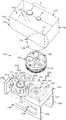
FIG. 1 is an exploded perspective view of a coin hopper according to a first embodiment of the present invention.
FIG. 2 is a plan view of the coin hopper according to the first embodiment of the present invention with the storage bowl removed.
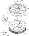
FIG. 3 is an exploded perspective view of a rotating disk used in the coin hopper according to the first embodiment of the present invention.
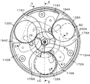
FIG. 4 is a plan view of a rotating disk used in the coin hopper according to the first embodiment of the present invention.
FIG. 5 is a rear view of the rotating disk used in the coin hopper according to the first embodiment of the present invention.
6 is a cross-sectional view taken along line AA in FIG.
7 is a cross-sectional view taken along line BB in FIG.
8 is a cross-sectional view taken along the line CC in FIG.
9 is a cross-sectional view taken along the line DD in FIG.
FIG. 10 is a front view of a drive cam used in the coin hopper according to the first embodiment of the present invention.
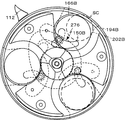
FIG. 11 is a front view for explaining the operation of the rotating disk used in the coin hopper according to the first embodiment of the present invention (in the middle of extrusion).
FIG. 12 is a front view for explaining the operation of the rotating disk used in the coin hopper according to the first embodiment of the present invention (end of extrusion).
FIG. 13 is a front view for explaining the operation of the rotating disk used in the coin hopper according to the first embodiment of the present invention (while retracting).
FIG. 14 is a front view for explaining the operation of the rotary disk used in the coin hopper according to the first embodiment of the present invention (full pull-in).
FIG. 15 is a front view for explaining the operation of the rotating disk used in the coin hopper according to the first embodiment of the present invention (in the middle of reverse rotation).
FIG. 16 is a front view for explaining the operation of the rotating disk used in the coin hopper according to the first embodiment of the present invention (end of reverse rotation).
FIG. 17 is a front view for explaining the operation of the rotating disk used in the coin hopper according to the first embodiment of the present invention (problem during reverse rotation).
FIG. 18 is a control block diagram of the coin hopper according to the first embodiment of the present invention.
FIG. 19 is a control flowchart of the coin hopper according to the first embodiment of the present invention.
FIG. 20 is a control timing chart of the coin hopper according to the first embodiment of the present invention.
図1に示すように、実施例1のコインホッパ100は、バラ積みされたコインCを回転ディスク106の回転によって一つずつ区分けした後、当該回転ディスク106の周方向へ送り出す機能を有し、ばら積み状態に多数のコインを保留する保留ボウル102と、その保留ボウル102を固定する取付ベース104、コインCを一つずつ区分けする回転ディスク106(区分け板154)、回転ディスク106の駆動装置108、受取体112、及び、コインCの受取搬送装置114、を含んでいる。しかし、受取体112、及び、受取搬送装置114は必須の構成ではない。なお、コインCは複数金種が想定され、少なくとも最大径コインLCと最小径コインSCとを有し、最大径コインLCと最小径コインSCとの間の直径の1又は2以上のコインを含む場合がある。したがって、本明細書においては、特定のコインに該当しない場合は、コインCと表示し、特定のコインを説明する場合は、最大径コインLC又は最小径コインSCと表示する。
As shown in FIG. 1, the
まず、保留ボウル102を説明する。
保留ボウル102は、多数のコインCをバラ積み状態に保留し、回転ディスク106に向けて送り込む機能を有する。
保留ボウル102は、大凡水平に配置された取付ベース104の上方に延在する縦向き筒型であって、上部116が断面矩形であり、下部118が断面円形をなし、上部116と下部118との接続は回転ディスク106側に向かって傾斜する底壁122が形成され、コインCが底壁122上を自重によって下部118に向かって滑り落ちるように構成されている。換言すれば、保留ボウル102は、底壁122が回転ディスク106に向かって下向きに傾斜しているヘッド部124と、コインCを投入するためのコイン投入口126と、回転ディスク106の少なくとも上側の外周を囲う外装部128を有している。
外装部128は、その下端面を取付ベース104に密着され、当該取付ベース104に着脱自在に固定されている。
下部118の断面円形部の高さは、最小径コインSCの直径よりも小さく形成され、コインCが下部118の内壁にもたれ掛かって立ち難いようにしてある。
外装部128は、円筒リング形であって、それによって囲われた円形空間は保留室130の底孔131を構成する。
したがって、上部116と下部118とにより全体として下すぼまりの保留室130が形成され、直径の異なるコインCは、保留ボウル102内、したがって、保留室130にバラ積み状態に保留され、傾斜する底壁122上を自重によって滑り落ち、回転ディスク106に送り込まれる。
さらに、回転ディスク106によって攪拌されるコインCは、様々に姿勢を変える中で、回転ディスク106の透孔132に落下する。
First, the holding
The holding
The
The
The height of the circular section of the
The
Therefore, the
Further, the coin C stirred by the
次に取付ベース104を図1及び図2を参照して説明する。
取付ベース104は、回転ディスク106を回転自在に支持し、保留ボウル102が着脱自在に固定され、駆動装置108が取り付けられる等の機能を有する。
取付ベース104は、矩形厚板からなる水平な載置台部134と、載置台部134を頂部に載せて保持する倒立チャンネル形の脚部136を含み、脚部136は略直角に立設された支持側壁138L、138Rと、載置台部134を載せる天板部142を含んでいる。
Next, the mounting
The mounting
The mounting
次に載置台部134を説明する。
載置台部134は、耐摩耗性の樹脂により成型された矩形の厚板状であり、例えば上面に回転ディスク106の下側に取り付けられた歯車144等が収納される円形の収納穴146が形成され、裏面には回転ディスク106の駆動装置108たる電気モータ148が取り付けられる。
収納穴146は、回転ディスク106よりは僅かに大きい直径の円形穴であり、回転ディスク106の大凡が没入される深さを有する。収納穴146の周囲の一部に凹状の出口溝151が形成されている。
収納穴146の中央には、押動体駆動装置260の一部が所定の高さで形成されている。
したがって、本実施例1において収納穴146は、円形のリング型の収納溝153に構成されている。
Next, the mounting
The
A part of the
Therefore, in the first embodiment, the
次ぎに脚部136を説明する。
脚部136は、取付ベース104を支持する機能を有する。
脚部136は、正面視門形であり、ベンダー等により平板を所定の角度で折り曲げて形成され、本実施例1において、天板部142は水平に配置されるが、傾斜されてもよい。
Next, the
The
The
次に、回転ディスク106を図3〜図6を参照して説明する。
回転ディスク106は、全体として電気モータ148から駆動力を受けて回転され、バラ積みされたコインCを一つずつ区分けし、当該回転ディスク106周方向へ送り出し、受取体112に受け渡す機能を有する。
回転ディスク106は実施例1においては、区分け板154、コイン保持板156及び歯車体158を含んでいるが、少なくとも区分け板154及びコイン保持板156を含んでいれば良い。
区分け板154、コイン保持板156及び、歯車体158は、全て一体に成型し、若しくは、選択的に二つを一体化し、又は、個別に構成した後、組み立てることができる。本実施例1においては、歯車体158がコイン保持板156と一体に構成されているが、これは回転ディスク106を回転駆動するための一例であるので、歯車体158は必須の構成ではない。
Next, the
The
In the first embodiment, the
The sorting
次に区分け板154を主に図2及び図3を参照して説明する。
区分け板154は、その全部若しくは一部を保留ボウル102の底孔131内に、又は、底孔131の直下に配置され、保留室130内のコインCを攪拌すると共に、コインCが1つずつ上から下へ落下して一つずつ区分けする機能を有し、本実施例1においては、所定の厚みを有する円板形であって、回転ディスク106の最上位に配置される。
Next, the sorting
Sorting
まず、区分け板154の上面の形状を説明する。
なお、本実施例1において、透孔132等の同一機能及び同一形状の部位が複数存在する場合、数字のみ付し、特に区別して説明を要する場合には該当数字にアルファベットのA、B又はCを付して説明する。
区分け板154は大凡全体として厚みを有する円形板状であり、本実施例1においては、中央突起162、保持面166及びリング167を含んでいるが、中央突起162及びリング167は必須の構成では無い。
First, the shape of the upper surface of the
In the
The sorting
次に中央突起162を説明する。
中央突起162は、底孔131内のコインCを攪拌する機能を有する。
中央突起162は、区分け板154の上面の中央に栽頭円錐形であって、区分け板154の回転軸線CEに対してそれぞれ同一半径位置に平面部162A、162B、162Cが形成されている。
Next, the
The
The
次に保持面166を説明する。
保持面166は、透孔132を画定し、かつ、コインCを攪拌する機能を有する。
保持面166は、当該中央突起162の周囲にリング形に形成された大凡平らな面である。
Next, the holding
The holding
The holding
次に透孔132を説明する。
透孔132は、コインCを自重により上から下へ落下させて、1つずつ区分けする機能を有する。
透孔132は、保持面166に形成され、使用される最大径コインLCよりも僅かに大径であって、上下に貫通し、等間隔で所定数、本実施例1では3個の透孔132A、132B、132Cが形成されている。しかし、透孔132の数は本実施例1に限られず、2個又は4個以上であってもよい。
したがって、各透孔132A、132B、132Cの間には、区分け板154の周縁側が拡開する扇形のリブ172A、172B、172Cが等間隔に形成される。リブ172A、172B、172Cのそれぞれには、中央突起162の基部から区分け板154の周縁に向かって平面視斧型の隆起部174A、174B、174Cが形成されている。
透孔132A、132B、132Cと隆起部174A、174B、174Cとの位置関係は同一であるので、隆起部174Cを代表して説明する。
隆起部174Cに対し回転方向前位に位置する透孔132Bとの間には、ほぼ同一幅であって、透孔132Bの周縁から隆起部174Cに向かう上向き傾斜部176Bが形成されている。上向き傾斜部176Bによって、コインCがこの上向き傾斜部176Bに案内されることで隆起部174Cを容易に乗り越えられるようにし、コインジャムの発生を防止する。
隆起部174Cの回転方向後位側における中央突起162の基部から周縁に向かう大部分においては透孔132Cの周縁からほぼ垂直に立ち上がる段差部178C(図8)が形成され、先端部は区分け板154の周縁方向へ直線的に延在する直状部182Cに形成され、直状部182Cと透孔132Cとの間は、透孔132Cの周囲から直状部182Cに向かう回転前位側斜面184C(図8)が形成されている。
また、区分け板154の周縁全周は、所定高さを有するリング167が形成されている。このリング167は、区分け板154を樹脂によって成型した場合、所定の強度を維持するため設けることが好ましいが、強度が十分な場合は設けることを要しない。リング167の上端は、隆起部174Cの上面よりも僅かに上方に位置するように設定され、隆起部上面との間は斜面又は凹面の接続部186Cに形成されている。接続部186Cに乗ったコインCが倒れやすくするためである。
貫通孔187A、187B、187Cが、隆起部174A、174C、174Cの周縁近傍において上下方向に貫通して形成され、区分け板154、及び、コイン保持板156を一体化するためのネジ189A、189B、189Cが貫通される。
区分け板154の回転軸線CEに沿って円形の取付孔188が形成され、後述の回転軸189の小径先端部190が挿入され、固定される。
Next, the through
The through-
The through-
Accordingly, fan-shaped
Since the positional relationship between the through
Between the raised
A stepped
A
Through
A
次ぎに、区分け板154の裏面191の形状が主に図5を参照して説明する。
区分け板154の裏面191には、周方向通路192A、192B、192C及びプッシャ194A、194B、194Cが各透孔132A、132B、132Cに対応して形成されている。本実施例1において、周方向通路192A、192B、192C及びプッシャ194A、194B、194Cは、同一機能及び形状がそれぞれ同一であるので、以下周方向通路192A及びプッシャ194Aを代表して説明し、周方向通路192B及び192Cについては、同一数字に対応するアルファベットB又はCを付して表示し、説明書を省略する。
Next, the shape of the
On the
まず周方向通路192Aを説明する。
周方向通路192Aは、透孔132Aに落下したコインCを区分け板164の周方向へ案内する機能を有する。
周方向通路192Aは、区分け板154の裏面に形成された断面倒立チャンネル形の溝196Aとコイン保持板156とによって構成されている。溝196Aは、区分け板154の回転軸線CEと透孔132Aの中心CSを通って延在する放射線RLAと平行に透孔132Aの端部から周方向へ向かって直線的に形成され、区分け板164の回転方向の前位に位置する細長平面状の前案内体198A、回転方向の後位に位置する細長平面状の後案内体202A、溝196Aの天面204A、及び、コイン保持板156の上面によって囲まれた断面矩形の通路である。したがって、前案内体198Aと後案内体202Aの基端は、中心CSを通り、かつ、放射線RLAに対し直角に交差する仮想線VLと透孔132Aの周縁とが交わる位置である。前案内体198Aと後案内体202Aの高さ(区分け板154の厚み方向)は、最厚コインの厚みよりも僅かに大きく形成されている。後案内体202Aは、区分け板164が正回転する場合、コインCの周面を押動して連れ回りさせる。前案内体198Aは、回転ディスク106が逆回転する場合、コインCの周面を押動して連れ回りさせる。
First, the
The
The
次ぎにプッシャ194Aを説明する。
プッシャ194Aは、コインCを最後に受取体112に向けて押し出す機能を有し、後案内体202Aに連続して区分け板154の周縁に位置する部分である。本実施例1において、後案内体202Aに対して約150度の角度をなす平面に形成され、後案内体202Aとは緩やかな曲線で接続されている。プッシャ194Aは、平面に限らず、弧状であってもよく、さらに、小さなベアリングを配置しても良い。要すれば、プッシャ194AはコインCの周面を押動するため、コイン周面に疵を付けない構造を採用することが好ましい。
Next, the
The
次ぎに押動体待機溝203Aを説明する。
押動体待機溝203Aは、待機位置SPに位置する押動体150Aの全体を収容する機能を有する。本明細書において、押動体150Aの全体を収容とは、完全に収容された状態と作用・効果において実施的に差異がない場合を言う。換言すれば、押動体150Aの全体が押動体待機溝203Aに実質的に収容された状態を言い、区分け板154の実質的真下とも言う。
押動体待機溝203Aは、透孔132Aの回転軸線CE側の下端部に連続して三日月形に形成されている。しかし、押動体待機溝203Aの形状は三日月形に制限されず、同一の機能を有すれば他の形状であっても良い。
Next, the pusher standby groove 203A will be described.
The
The
次にコイン保持板156を主に図3及び図6を参照して説明する。
コイン保持板156は、透孔132に落下したコインCをその上面に保持する機能を有し、区分け板154と同一径の円盤状をなしている。本実施例1においてコイン保持板156は、上面が平面であり、中央部下面に回転軸線CEを囲む円柱状の取付ボス205が所定の長さで形成されている。したがって、区分け板154のリブ172の下面をコイン保持板156の上面に実質的に密着させることにより、透孔132A、132B、132Cの真下にコイン保持空間206が形成されると共に周方向通路192A、192B、192Cが形成される。よって、コイン保持空間206と周方向通路192A、192B、192Cの高さは同一であり、最厚コインの厚みよりも僅かに高く形成されている。したがって、透孔132に落下したコインCは、コイン保持空間206においてコイン保持板156に面接触して保持され、コイン保持板156上を滑ってコイン保持空間206から周方向通路192A、192B、192Cを通って回転ディスク106の外周側へ移動することができる。
押動体150A、150B、150Cは、待機位置SPから押出位置PPへ移動し、また、押出位置PPから待機位置SPへ移動することにより、コイン保持空間206に進退可能である。
取付ボス205の軸心部に軸孔208が貫通している。軸孔208は下部の大径部212と上部の小径部214によって形成され、大径部212と小径部214との間には段部216が形成されている。
回転軸189は、下部の大径軸部218と上部の小径先端部190により構成され、それらの間には段差である肩部220が形成される。回転軸189は、取付ベース104の裏面に取り付けられた減速機219の出力軸であり、大径軸部218は軸孔208、小径先端部190は小径部214を貫通し、肩部220を段部216で受けることにより、回転ディスク106の高さ位置を決定し、小径先端部190のネジ部にナット222をねじ込むことにより、区分け板154及びコイン保持板156を固定して一体化してある。
減速機219は、その裏面に固定された電気モータ148によって回転駆動される。
Next, the
The
The
The
Reducer 21 9 is rotationally driven by an
次に歯車体158を図3及び図6を参照して説明する。
歯車体158は、被動歯車224を回転駆動する機能を有する。
本実施例1において、歯車体158はコイン保持板156の外周縁から下方へ向かって所定の長さで形成した円筒部225の外周面に歯車144を形成することにより構成されている。換言すれば、コイン保持板156と円筒部225を一体に形成した有底円筒体を逆さにした形状であって、円筒部225の周面を歯車144に形成してある。歯車144の外径はコイン保持板156と同一であり、樹脂成型品、板金プレス加工品等が使用される。なお、歯車144は、後述の被動歯車224を駆動する機能を有するので、被動歯車224を別の手段によって回転ディスク106と同期回転させることにより、歯車体158を設けないことができる。
Next, the
The
In the first embodiment, the
本実施例1においては、区分け板154とコイン保持板156が一体化装置226によって一体化されている。一体化された場合、押動体待機溝203の下面はコイン保持板156の上面によって覆われることから、コイン保持空間206側がスリット型の開口241に形成された押動体待機空間244が形成される。
一体化装置226は、リブ172に形成された貫通孔187A、187B、187Cに挿入したネジ189A、189B、189Cをコイン保持板156に形成されたネジ孔234A、234B、234Cにねじ込むことにより一体化してある。しかし、一体化装置226はこれに限らず、区分け板154、コイン保持板156及び歯車体158を一体成型する等、他の構造又は手段を用いることができる。
In the first embodiment, the sorting
次ぎに回転ディスク106の配置を図1及び図6を参照して説明する。
回転ディスク106は、区分け板154の上面が取付ベース104の上面とほぼ一致するように収納穴146内に回転自在に配置される。
保留ボウル102の下部118の下端面は、底孔131の軸心が回転軸189の軸心と一致するように取付ベース104の上面に面接触されて取付ベース104に固定される。この取り付けられた状態において、底孔131の内縁は、図6に示すように、リング167の上に被さるように配置されている。保留されたコインCが少なくなった場合に、コインCが保留ボウル102の内周面に寄りかかり、コインCの下周面がリング167の上に載った状態を継続し、透孔132に落下しない事態を回避するためである。
なお、周方向通路192A、192B、192Cの外周端は、大凡4分の3周が収納穴146の内周面に相対し、受取体112の側方に於ける約4分の1周で構成する出口溝151に相対する。換言すれば、コインCは周方向通路192A、192B、192Cの端面全体が出口溝151に相対している場合、出口溝151へ移動することができる。
Next, the arrangement of the
The
The lower end surface of the
The outer peripheral ends of the
次ぎに電気モータ148を説明する。
電気モータ148は、直流電気モータであり、電気的接続を逆にすれば、逆転される可逆電気モータである。換言すれば、区分け板154は正転及び逆転が可能である。本実施例1において、回転ディスク106が図2において反時計方向に回転される場合が正転であり、時計方向に回転される場合が逆転である。
Next, the
The
次ぎに押動装置152を主に図3を参照して説明する。
押動装置152は、透孔132に落下し、コイン保持板156上に保持されているコインCを所定のタイミングで周方向通路192を通って区分け板154の周方向へ移動させる機能を有する。
本実施例1において、押動装置152はコイン保持板156に一体化され、押動体150A、150B、150C及び押動体駆動装置260を含んでいる。
Next, the pushing
The pushing
In the first embodiment, the pushing
まず、押動体150A、150B、150Cを説明する。
押動体150A、150B、150Cは、透孔132A、132B、132Cに落下し、コイン保持板156上に保持されているコインCを所定のタイミングで周方向通路192を通って回転ディスク106の周方向へ移動させる機能を有する。
押動体150A、150B、150Cは、各透孔132A、132B、132Cにそれぞれ対応して設けられているが、押動体150Bを代表して説明し、他の押動体150A、150Cの対応する部分には同一数字にA又はCを付して説明を省略する。
押動体150Bには、支軸242B側が幅広であって、先端に向かうにつれて幅細となる弧状に形成され、その幅広側の端部に下向きの支軸242Bが固定されている。支軸242Bは、押動体保持溝203Bに相対する位置におけるコイン保持板156に形成された軸孔244Bに挿入され、コイン保持板156の下面側に配置したワッシャ246B及びEリング248Bによって脱落しないよう回転自在に取付けられている。そして、コイン保持空間206側の押動縁250Bは、押動体150Bが待機位置SPに位置する場合、区分け板154を平面視した場合、透孔132Bの内縁に重なるよう、又は、内縁から僅かに奥まった位置に設定される。
押動体150Bの中間からフォロワー支軸252Bが下向きに固定され、コイン保持板156に、軸孔244Bの軸線を支点に弧状に形成した第3貫通孔254Bを貫通して延在され、先端部にはカムフォロワ256Bが回転自在に取り付けられ、Eリング258Bによって抜け止めされている。カムフォロワ256Bは、後述の溝カム264内に挿入配置される。
第3貫通孔254Bの一端は、押動体150Bの待機位置SPにおけるフォロワー支軸252Bの近傍に形成され、他端は、押動体150Bの押出位置PP迄、移動可能である。
前記した構成により、押動体150Bは支軸242Bを支点に揺動運動することができ、その揺動範囲は、保留ボウル102内にバラ積み状態で保留されたコインCに対して、区分け板154の下方に隠れた待機位置SPと、透孔132Bの下方へ進行し、コイン保持空間206に位置する押出位置PPとの範囲である。押動体150Bの揺動運動は、押動体駆動装置260によって行われる。
First, the
The
The
In the
The
One end of the third through
With the configuration described above, the
次ぎに、押動体駆動装置260を主に図1及び図10を参照して説明する。
押動体駆動装置260は、押動体150を所定のタイミングで待機位置SPと押出位置PPとに移動させる機能を有する。
押動体駆動装置260は、本実施例1においては取付べース104の収納穴146内であって、かつ、コイン保持板156の下方において固定状態に配置された駆動カム262である。
駆動カム262は、外郭縁266と内郭縁268とによって全体として所定幅の連続する溝カム264であり、基端部272、先端部274、押出接続部276、戻り接続部278及び逆転時溝カム302を含んでいる。
溝カム264の基端部272は半円形であり、その半円の中心は、回転ディスク106の回転軸線CEと一致する。
先端部274は回転軸線CEから離れた第2軸線CE2を中心にした基端部272よりも小半径の半円形(小半円形)である。
押出接続部276は基端部272と先端部274との図10における右側端部を接続する弧状縁である。
すなわち、押出接続部276はカムフォロワ256が待機位置SPから押出位置PPへ向かって押し出される途上にある。
戻り接続部278は基端部272と先端部274との図10における左側端部を弧状線によって接続する。戻り接続部278は、カムフォロワ256が押出位置PPから待機位置SPへ戻される途上にある。換言すれば、後述するように戻り接続部278は押動体150が正転時に前記押出位置PPから前記待機位置SPへ向かって徐々に移動する区間である。
そして、溝カム264は基端部272、先端部274、押出接続部276及び戻り接続部278によって、全体として卵型に形成されている。
換言すれば、外郭縁266は、回転ディスク106の回転軸線CEを中心として第1半径R1で形成された大凡半円形の外郭基端縁282、第2軸線CE2を中心に外郭基端縁282よりも小径の第2半径R2で形成されたほぼ半円形の外郭先端縁284、及び、外郭基端部282と外郭先端縁284の右側間を緩やかな曲線で結ぶ右つなぎ外郭縁286及び外郭基端縁282と外郭先端縁284の左側間を緩やかな曲線で結ぶ左つなぎ外郭縁288で形成された卵形である。外郭縁266と内郭縁268は、カムフォロワ256がそれらの間を移動できるように所定の一定間隔を有している。換言すれば、カムフォロワ256は、外郭縁266又は内郭縁268によって案内される。
内郭縁268は、外郭縁266の内側に外郭縁266と大凡相似形に形成された卵形である。すなわち、回転ディスク106の回転軸線CEと同心に第3半径R3で形成された大凡、半円形の内郭基端縁292、第2軸線CE2を中心に内郭基端縁292よりも小径の第4半径R4で形成されたほぼ半円形の内郭先端縁294、及び、内郭基端縁292と内郭先端縁294の右側間を緩やかな曲線の右つなぎ内郭縁296で接続されている。押出接続部276は、先端部274へ向かって順次回転軸線CEから離れるように位置し、戻り接続部278は先端部274側から回転軸線CEへ近づくように位置する。
さらに、図2に示すように先端部274は、回転ディスク106に対しては、区分け板154の回転軸線CEを通る垂線に対し左側に偏倚して配置される。換言すれば、溝カム264は卵型を回転軸線CEを中心に僅かに反時計方向に回動させた、傾き卵形に形成されている。
Next, the
The
In the first embodiment, the
The
The
The
In other words, the push-out connecting
The
The
In other words, the outer edge 266 rotates approximately semicircular outer
The
Further, as shown in FIG. 2, the
回転ディスク106、したがって区分け板154が正転される場合、駆動カム262は固定状態であるため、回転ディスク106の回転に伴ってカムフォロワ256は溝カム264の外郭縁266又は内郭縁268に案内され、押動体150はカムフォロワ256に連動して待機位置SP又は押出位置PPに移動される。押動体150の位置は、支軸242とカムフォロワ256との位置関係によって定まる。すなわち、カムフォロワ256が支軸242よりも回転軸線CEに大幅に近い位置に位置する場合、押動体150は支軸242回りを相対的に時計方向に回動され、押動体150の押動縁250は回転軸線CEに近い位置に位置され、当該位置から区分け板154の周方向へ移動された場合、支軸242回りを反時計方向へ回動され、押動縁250は回転軸線CEから離されてコイン保持空間206に進行する。
なお、カムフォロワ256は、内郭縁268側、詳しくは少なくとも戻り接続部278において内郭縁268側に付勢されるようすることが好ましい。付勢手段は、バネ、重り等適宜選択出来るが、コストとの関係から、重力、すなわち、構造体の重量を利用する構造が好ましい。重力を利用する場合、取付ベース104が傾斜し、押動体150、カムフォロワ256等の重量によって、支軸242回りに内郭縁268に近づくようモーメントが作用するように構成する必要がある。本実施例1において、取付ベース104は水平に配置されているので、バネ等によってカムフォロワ256が内郭縁268側に移動するように付勢されている。
したがって、回転ディスク106が正回転(図2において反時計方向)をした場合、押動体150は区分け板154と共に反時計方向に一体回転する。カムフォロワ256が溝カム264の基端部272に位置する場合、回転軸線CEからの距離が同一の第1半径R1の外郭基端縁282又は第3半径R3の内郭基端縁292によって案内されるので、区分け板154、したがって、透孔132に対しても一定の位置関係を保つ。
すなわち、基端部272において、押動体150は待機位置SPに保持され、押動体150は、それぞれ保留室130のコインCに対しては、区分け板154の下方に隠れるように位置される。
詳細には、カムフォロワ256が基端部272によって案内される場合、押動体150は待機位置SPに位置するように支軸242とカムフォロワ256との位置が定められている。換言すれば、区分け板154の回転軸線CEと同心の基端部272によってカムフォロワ256が案内されるので、押動体150は待機位置SPを継続する(図11における押動体150B、150C)。
カムフォロワ256が押出接続部276に移動した場合、カムフォロワ256は、区分け板154の周方向へ移動されることから、押動体150は支軸242回りを反時計方向に回動され、押出位置PPへ向かって移動し、これにより、押動体150は透孔132下方のコイン保持空間206へ進行しつつ当該コイン保持空間206に保持されているコインCを周方向通路192へ押し出す(図11における押動体150A)。
カムフォロワ256が先端部274に位置した場合、押動体150は最も反時計方向に回動され、コインCは押出位置PPへ移動される。押出位置PPは、図12に示すように透孔132Aの中央まで進出し、押動縁250Aは透孔132Aの中心よりも区分け板154の外周縁側に位置する。この場合において、最小径コインSCであっても、受取体112とプッシャ194Aとの間に挟まれた際、最小径コインSCのコイン中心SCCが受取体112とコインCとの接点P1、及び、プッシャ194とコインCとの接点P2を結んだ第1直線SLよりも回転軸線CEから遠い位置に位置するよう設定されている。このコイン中心SCCの位置は、回転軸線CEからより遠いことが好ましい。
図13に示すように、カムフォロワ256が、戻り接続部278に達すると、回転軸線CEからの距離が徐々に近づくので、押動体150Aは支軸242回りを図2において時計方向へ回動され、換言すれば待機位置SPへ向かって移動され、押動体150Aが基端部272に達したときは待機位置SPに位置される。
When the
The
Therefore, when the
That is, at the
Specifically, when the
When the
When the
As shown in FIG. 13, when the
本発明にかかる駆動カム262は、さらに、逆転時待機位置保持カム300を含んでいる。
逆転時待機位置保持カム300は、区分け板154が逆転された際、押動体150が待機位置SP若しくはその近くから押出位置PPへ向かって移動されないように待機位置SPに保持する機能を有する。ここでいう待機位置SPも、実質的に待機位置SPに位置する場合と同一の作用・効果を有する場合を含むものである。換言すれば、押動縁250がコイン保持空間206に進行して透孔132の下方に位置する場合であっても、同一の作用・効果を有する場合、待機位置SPに保持される範囲に含まれるものである。
本実施例1において、逆転時待機位置保持カム300は、逆転時溝カム302であり、基端部272の内郭基端縁292の戻り接続部278側、換言すれば、図10における回転軸線CEよりも左側を第3半径R3と同一半径で更に四分の一周延長することにより、逆転時内縁304を形成し、結果、内郭基端縁292は全体として大凡四分の三周が第3半径R3で形成されている。内郭基端縁292に対し、カムフォロワ256の直径よりも僅かに離れて逆転時外縁305が形成されている。したがって、逆転時溝カム302は、内郭縁先端縁294よりも回転軸線CEに近い位置において、すなわち、逆転時溝カム302は図10に示すように、先端部274において左側から右側へ向かって食い込むように形成されている。結果として、内郭縁268は全体として、下部が円形であって、先端部がフック状の勾玉形状をしている。したがって、駆動カム262は、卵形の外郭縁266と勾玉形の内郭縁268とで画定された全体として卵形のオーバルリンク形であり、先端部274の押出接続部276側から戻り接続部278へ向かって、換言すれば、図10において右側から左側に向かって鎌形に突出する突き当たり306を有する形状を有する。
さらに、駆動カム262は卵形であるが、その対称軸SL2は図10において垂立線に対して反時計方向へ約30度回動されて固定状態に配置されている。
駆動カム262の傾きは、受取体112との配置の関係でこのように回動されているが、コインCの動きを考慮すると、この程度の傾きを有していることが好ましい。しかし、これに限られることはない。
逆転時溝カム302は、区分け板154の逆転時に機能する。すなわち、区分け板154が逆転した場合において、基端部272における戻り接続部278側、図10において回転軸線CEの左側から逆転時溝カム302の突き当たり306に至る間に位置するカムフォロワ256は、内郭縁268に沿って、詳しくは逆転時内縁304に案内されつつ逆転時溝カム302の突き当たり306まで移動可能である。逆転時内縁304は、内郭基端縁292と同一の第3半径R3で形成されているため、押動体150は待機位置SPに保持されることから、図17に示すように、コインCがコイン保持空間206に位置していても周方向通路192へ移動されることはない。換言すれば、コインCが周方向へ移動されて外周縁に押し付けられないので、逆転時溝カム302の存在範囲で区分け板154は逆転が可能である。
The
The reverse standby
In the first embodiment, the reverse rotation standby
Further, although the
The inclination of the
The reverse
次に回転ディスク106の駆動装置108が主に図6を参照して説明される。
駆動装置108は、回転ディスク106、したがって、区分け板154及びコイン保持板156を所定の速度で正転又は逆転させる機能を有する。
本実施例1において、駆動装置108は、電気モータ148、及び、減速機219を含んでいる。
減速機219は取付ベース104の裏面に固定され、その出力軸たる回転軸189が溝カム264の基端部272の回転軸線CEと軸線が一致するように配置して上側に突出され、その先端部に前述のように回転ディスク106が固定されている。
Next, the driving
The
In this
Reducer 21 9 is fixed to the rear surface of the mounting
次にコインの受取体112を主に図2を参照して説明する。
受取体112は、区分け板154によって一つずつ区分けして送られてくるコインCを区分け板154(回転ディスク106)の周方向へ案内する機能を有する。
本実施例1において、受取体112は、出口溝151を形成する一方の段部からなる第1案内縁312である。第1案内縁312は、収納穴146から区分け板154の周方向へ離れるように延在している。本実施例1において、第1案内縁312は押動片314の第2回転軸線RCを中心にした所定半径の円弧部316及び円弧部316に続く直状部318を含んでいる。円弧部316は、収納穴146に対し大凡法線方向に延在した後、徐々に大凡45度方向を変えて案内する機能を有する。直状部318は、円弧部316の終端から直線的に延在し、区分け板154から遠ざかる方向に直線的に案内する機能を有する。
Next, the
Receiving up
In the first embodiment, receiving up
次ぎにコインホッパ100のコインセンサ308を説明する。
コインセンサ308は、出口319から送り出されたコインCを検出し、コイン検知信号CDSを上位制御回路344に出力する機能を有し、公知の光電センサ、磁気センサ又は機械的センサ等を用いることができる。
本実施例1においてコインセンサ308は、透過式の光電センサであり、取付ベース104に図示しないブラケットにより固定されている。
Next, the
The
In the first embodiment, the
次ぎに押動片314を主に図2を参照して説明する。
押動片314は、押動体150によって押し出されたコインCを円弧部316及び直状部318に沿わせつつ移動させ、出口319から送り出す機能を有する。
詳しくは、押動片314は、回転ディスク106と連動して回転し、押動体150によって周方向通路192を通って出口溝151に移動したコインCを押動し、円弧部316及び直状部318に沿わせて移動させる機能を有する。本実施例1において、押動片314は第2回転軸線RCに対し点対称に配置された2個の押動片314Aと314Bを有し、区分け板154が3個の透孔132A、132B、132Cを有することから、回転ディスク106に対して1.5倍の回転速度で回転される。換言すれば、回転ディスク106が2回転する間に押動片314A及び314Bは3回転され、結果として、各透孔132A、132B、132Cから一枚ずつ送り出されるコインCを押動片314A又は314Bによって一つずつ受取体112に押し付けつつ押動することにより当該受取体112に沿って移動させる。
押動片314は、第2回転軸線RC回りを回転する円板体320の上面から上向きに突出し、第2回転軸線RCを中心とする弧状に形成された小片であり、出口溝151の底面において所定の高さで突出している。この突出量は最大厚みのコインCよりも僅かに大きく形成され、受取体112の高さとほぼ同一である。
円板体320は、その下方に配置された被動歯車224と同心に一体化されている。
Next, the pushing
The pushing
Specifically, the pushing
The
The
次ぎに被動歯車224を説明する。
被動歯車224は、歯車144と噛み合って図1において時計方向に回転駆動される。
被動歯車224は、取付ベース104内の円盤形空間に回転自在に配置され、一部が収納穴146内に突出し、歯車144と噛み合っている。
歯車144と被動歯車224との直径比、即ちギヤ比は、3対2である。これにより、3つの透孔132A、132B、132Cと2つの押動片314A、314Bとが所定の位相で回転する関係に構成される。すなわち、図14に示すように、押動体150が押出位置PPに位置した直後に、押動体150によって押し出されたコインCを受取体112に向けて押動するようにタイミングが設定されている。
図2に示すように、押動片314は押動を開始する際、第2回転軸線RCを中心とし、かつ、最小径コインSCの中心SCCまでの距離を第5半径R5とする円弧ACよりも僅かに第2回転軸線RCに近い位置においてコインCの周面と接するように設定されている。これにより、押動片314はコインCの円弧周面SCSを大凡直角方向から押すので、最小径コインSCの受取体112に対する押圧力を低く抑制するように作用するので、コインCの移動がスムーズになる利点がある。
Next, the driven
The driven
The driven
The diameter ratio between the
As shown in FIG. 2, when the pushing
次ぎに出口溝151の一方を画定する第2案内縁322を説明する。
第2案内縁322は、本実施例1では取付ベース104と一体に形成された弧状壁323と直状壁324とにより構成されている。
弧状壁323は、押動体150によって押し出されたコインCが押動片314側へ移動するよう案内する機能を有する。すなわち、収納穴146の反受取体112側の端部付近から収納穴146の周方向、かつ、受取体112側へ指向するように弧状をなしている。
直状壁324は、取付ベース104とは別体のナイフ形状のナイフ326の直状の一側面によって形成され、弧状壁323に連続し、直状部318を指向するように第2回転軸線RC近傍まで延在している。したがって、ナイフ326の裏面には、押動片314が移動し得る円弧状の通過溝(図示せず)が形成されている。
したがって、本実施例1において、出口溝151は図2に示すように、第1案内縁312と第2案内縁322とによって全体としてS字型を呈し、収納穴146に連続して左側に湾曲した後、右側へ湾曲する形状をなしている。よって、コインCは第1案内縁312と第2案内縁322によって案内されつつ、押動片314によって出口319側へ移動され、出口319から送り出され、コインセンサ308によって検出される。
Next, the
In the first embodiment, the
The arc-shaped
Therefore, in the first embodiment, as shown in FIG. 2, the
次に電気モータ148の制御回路330が図18を参照して説明される。
電気モータ148は、給電回路332に介設されたスイッチング回路334を介して直流電源336に接続されている。スイッチング回路334と電気モータ148との間の給電回路332には過負荷検出回路338が介設され、過電流を検出した場合、過負荷信号ORSをホッパ制御回路342に出力する。
ホッパ制御回路342は、過負荷検出回路338から過負荷信号ORS、及び、上位装置の上位制御回路344からの親制御信号の1つである払出信号DPSに基づいて正転信号RDS又は再起動信号ARS、逆転1信号CRS1、逆転2信号CRS2、又は、停止1信号STS1、停止2信号STS2、停止3信号STS3をスイッチング回路334に対し出力する。ホッパ制御回路342は、例えばマイクロプロセッサによって構成される。
スイッチング回路334は、正転信号RDS又は再起動信号ARSを受信した場合、電気モータ148の給電回路332を正転接続し、逆転1信号CRS1、逆転2信号CRS2を受信した場合逆転接続し、停止信号STS、停止1信号STS1、停止2信号STS2、停止3信号STS3を受信した場合、開路する。
なお、制御回路330は、取付ベース104の裏面等に固定されている。
Next, the control circuit 330 of the
The
The
When the forward rotation signal RDS or the restart signal ARS is received, the
The control circuit 330 is fixed to the back surface of the mounting
次ぎに上位制御回路344を説明する。
上位制御回路344は、上位機器の制御をする他、ホッパ制御回路342に対し払出信号DPSを出力すると共に、コインセンサ308からのコイン検知信号CDSを計数し、その計数値が所定数になった場合、及び、ホッパ制御回路342からのエラー信号ERSに基づいて、ホッパ制御回路342に対する払出信号DPSの出力を停止する機能を有する。
上位制御回路344は、例えば、マイクロプロセッサによって構成される。
Next, the
Higher-
The
次に、ホッパ制御回路342の作用を図19のフローチャートをも参照して説明する。
まず通常の作用(コイン送り出し)について説明する。
コインCを送り出す場合、上位制御回路344は払出信号DPS(図20参照)をホッパ制御回路342に対し出力する。
ホッパ制御回路342においては、ステップS1において、払出信号DPSがoffからonに変わったか判別し、払出信号DPSがoffからonに変わった場合、ステップS2へ進み、払出信号DPSがonからoff、又は、offを継続する場合、ステップS3に進む。したがって、ステップS1は上位制御回路344からの払出指令を判別している。
Next, the operation of the
First, the normal operation (coin feeding) will be described.
When the coin C is sent out, the
In the
ステップS2において、ホッパ制御回路342は正転信号RDSを出力し、ステップS3へ進む。正転信号RDSを受信したスイッチング回路334は、給電回路332を正転接続するため、電気モータ148は正転し、結果として回転ディスク106は図2において反時計方向へ所定の速度で回転され、前述のようにコインCが一枚ずつ出口溝151へ送り出され、押動片314A又は314Bによって押動されて受取体112に沿って移動され、最終的に出口319から送り出され、コインセンサ308によって検知される。コインセンサ308は、コインCの検知によってコイン検知信号CDSを上位制御回路344へ出力する。
In step S2, the
ステップS3において、払出信号DPSがonからoffに変わったか、又は、Offのままであるか判別し、Offに変わらない場合、又は、Offのままである場合ステップS4へ進み、Offに変わった場合ステップS5へ進む。したがって、ステップS3は、払出指令の解消を判別している。 In step S3, it is determined whether the payout signal DPS has changed from on to off or remains off. If not, or if it remains off, proceed to step S4 and change to off. Proceed to step S5. Therefore, step S3 determines whether or not the payout command has been canceled.
ステップS4において、再起動回数が許容回数ARN以内であるか否か判別し、許容回数ARNを超える場合、再起動できないのでステップS5へ進み、許容回数ARN以内である場合はステップS6へ進む。したがって、ステップS4は再起動可否判別を行っている。 In step S4, it is determined whether or not the number of restarts is within the allowable number of times ARN. If the number of restarts exceeds the allowable number of times ARN, the process cannot be restarted and the process proceeds to step S5. Therefore, step S4 determines whether or not to restart.
ステップS5において、ホッパ制御回路342は停止信号STSを出力した後、ステップS1へ戻る。
停止信号STSに基づいて、スイッチング回路334は開路を継続し、電気モータ148、したがって、回転ディスク106は静止状態を継続する。したがって、払出信号DPSが出力されていない間、ステップS1、S3、又はS4、及び、S5をループする、換言すれば回転ディスク106は停止を継続する。
In step S5, the
Based on the stop signal STS, the
ステップS6において、正転信号RDS又は再起動信号ARS以外の信号、即ち、停止信号STS、停止1信号STS1、逆転1信号CRS1、停止2信号STS2、逆転2信号CRS2又は停止3信号STS3が出力されているか判別し、これらが出力されている場合、及び、無信号の場合、ステップS7へ進み、これらが出力されていない場合、したがって正転信号RDS(及び、再起動信号ARS)が出力されている場合、ステップS8へ進む。したがって、ステップS6は正転指令を判別している。
In step S6, a signal other than the forward rotation signal RDS or the restart signal ARS, that is, the stop signal STS, the
ステップS8において、過負荷停止信号OSSが出力されているか判別し、出力されている場合ステップS9へ進み、出力されていない場合ステップS10へ進む。したがって、ステップ8は、過負荷停止判別を行っている。過負荷停止信号OSSが判別された場合、後述の回転停止処理、逆相ブレーキ処理、完全停止処理、逆転処理、逆転停止処理、及び、再起動処理を行う起点である。
過負荷停止信号OSSは、過負荷検出回路338からの過負荷信号ORS、例えば、コインCの払い出し過程において、コインCが区分け板154と保留ボウル102との間で突っ張り棒を呈する、所謂コインジャムが生じ、回転ディスク106が回転しなくなることがある。この場合、電気モータ148は回転を継続しようとするため、給電回路332に所定値を超える過電流が流れ、過電流検出回路338は過負荷信号ORSを出力する。この過負荷信号ORSが所定時間OT(図20)継続したことを判別した場合、ホッパ制御装置342は過負荷停止信号OSSを出力する。
In step S8, it is determined whether or not the overload stop signal OSS is output. If it is output, the process proceeds to step S9, and if it is not output, the process proceeds to step S10. Therefore, in step 8, overload stop determination is performed. When the overload stop signal OSS is determined, this is a starting point for performing a rotation stop process, a reverse phase brake process, a complete stop process, a reverse rotation process, a reverse rotation stop process, and a restart process, which will be described later.
The overload stop signal OSS is an overload signal ORS from the
ステップS10において、ホッパ制御回路342はスイッチング回路334に対し正転信号RDSを出力した後、ステップS11に次いでステップS12を実行した後、ステップS1へ戻る。
In step S10, the
ステップS11において、コインセンサ308からのコイン検知信号CDSの存在を判別し、
コイン検知信号CDSを検知した場合、ステップS12へ進み、検知しない場合ステップS1へ戻る。コインセンサ308からコイン検知信号CDSが出力されるということは、コインンジャムが解消されたことを意味するため、ステップS11はコインジャムの解消を判別している。
In step S11, the presence of the coin detection signal CDS from the
If the coin detection signal CDS is detected, the process proceeds to step S12, and if not detected, the process returns to step S1. The fact that the coin detection signal CDS is output from the
ステップS12において、ステップS37において演算記憶した再起動回数をゼロにリセットする。
したがって、ステップS1〜S4、S6、S8、S10、S11、及び、S12の流れが正常なコインCの払出状態である。
したがって、払出信号DPSが出力され、かつ、再起動回数が許容回数ARN以内であって、正転信号RDSが出力され、かつ、過負荷信号ORSが出力されていない間、ステップS1、S3、S4、S6、S8、S10、S11、及び、S12をループする、換言すれば回転ディスク106は正転を継続する。この正転が継続している間、上位制御回路344において、コイン検知信号CDSを計数し、自己が定めた払出設定値と比較し、一致した場合、ホッパ制御回路342へ停止信号を出力する。すなわち、払出信号DPSの出力を中止するので払出信号DPSはonからoffになるので、ステップS3においてそれが判別され、ステップS5へ進む。例えば、払出設定値を10に設定した場合、コインセンサ308からのコイン検知信号CDSを10個受信するまで払出信号DPSの出力を継続し、10個の受信を判別した場合、払出信号DPSの出力を停止する。
払出信号DPSの出力が停止した場合、ステップS3からステップS5へ進み、ホッパ制御回路342はスイッチング回路334へ停止信号STSを出力する。スイッチング回路334は、この停止信号STSによって給電回路332を開路するので、電気モータ148、したがって回転ディスク106は慣性回転後に停止し、コインCの払い出しが停止される。
In step S12, the number of restarts calculated and stored in step S37 is reset to zero.
Accordingly, the coins C are paid out normally in the flow of steps S1 to S4, S6, S8, S10, S11, and S12.
Therefore, while the payout signal DPS is output, the number of restarts is within the allowable number of times ARN, the normal rotation signal RDS is output, and the overload signal ORS is not output, steps S1, S3, S4 , S6, S8, S10, S11, and S12 are looped, in other words, the
When the output of the payout signal DPS is stopped, the process proceeds from step S3 to step S5, and the
次に回転停止処理を説明する。
ステップS6において、停止1信号STS1が存在するか判別し、停止1信号STS1が存在しない場合、ステップS13へ進み、存在する場合はステップS14へ進む。
Next, the rotation stop process will be described.
In step S6, it is determined whether or not the
ステップS9において、停止1信号STS1を出力した後、ステップS14へ進む。
停止1信号STS1に基づいてスイッチング回路334は給電回路332を開路するので、電気モータ148、したがって、回転ディスク106は慣性によって回転し、最終的に静止する。
In step S9, after outputting the
Since the
ステップS14において、第1計時時間T1の計時を開始した後ステップS15へ進む。 In step S14, timing of the first timing time T1 is started, and then the process proceeds to step S15.
ステップS15において、第1計時時間T1が経過したか判別し、経過した場合ステップS16へ進み、経過しない場合ステップS17へ進む。この第1計時時間T1は、給電回路332の開路後、逆相ブレーキを作用させるまでの空走期間であるので、極めて短時間でよい。したがって、停止1信号STS1は回転ディスク106の回転停止処理の起点となる信号である。
In step S15, it is determined whether or not the first clock time T1 has elapsed. If it has elapsed, the process proceeds to step S16, and if not, the process proceeds to step S17. The first time measurement time T1 is an idling period from when the
ステップS16において、スイッチング回路334に逆転1信号CRS1を出力した後、ステップS19へ進む。
In step S16, after the
ステップS17において、停止1信号STS1をスイッチング回路334に対し出力し、ステップS1へ戻る。すなわち、停止1信号STS1が出力されている間は、ステップS1、S3、S4、S6、S7、S14、S15、及び、S17をループし、スイッチング回路334は給電回路328を開放するので、電気モータ148、しがって、回転ディスク106は慣性回転する。
In step S17, the
次に逆相ブレーキ処理について説明する。
ステップS13において、逆転1信号CRS1が出力されているか判別し、出力されていない場合ステップS18へ進み、出力されている場合ステップS19に進む。
Next, the reverse phase brake process will be described.
In step S13, it is determined whether or not the
ステップS19において、第2計時時間T2の計時を開始した後、ステップS20へ進む。 In step S19, after measuring the second time T2, the process proceeds to step S20.
ステップS20において、第2計時時間T2を計時したか判別し、計時を判別した場合ステップS21へ進み、計時を判別しない場合、ステップS22へ進む。 In step S20, it is determined whether or not the second timing time T2 has been measured. If the timing has been determined, the process proceeds to step S21. If the timing has not been determined, the process proceeds to step S22.
ステップS22において、逆転1信号CRS1を出力し、ステップS1へ戻る。したがって、払出信号DPSが出力され、かつ、再起動回数が許容回数ARN以内であって、かつ、逆転1信号CRS1が出力されている間、ステップS1、S3、S4、S6、 S7、S13、S19、S20、及び、S22をループする。換言すれば、第2計時時間T2の間、電気モータ148、したがって、回転ディスク106には逆転トルクが作用される。第2計時時間T2は、慣性力で回転している電気モータ148及び回転ディスク106を急速に停止するための逆相ブレーキを作用させるため、回転ディスク106がほぼ停止状態になるまで継続すれば十分である。したがって、逆転1信号CRS1は逆相ブレーキ処理の起点になる信号である。第2計時時間T2は第1計時時間T1の10倍程度が好ましい。
In step S22, the
次に完全停止処理を説明する。
ステップS18において、停止2信号STS2が出力されているか判別し、出力されていない場合ステップS23へ進み、出力されている場合ステップS24へ進む。
Next, the complete stop process will be described.
In step S18, it is determined whether or not the
ステップS24において、第3計時時間T3の計時を開始し、ステップS25に進む。 In step S24, timing of the third timing time T3 is started, and the process proceeds to step S25.
ステップS25において、第3計時時間T3に達したか判別し、第3計時時間T3に達した場合ステップS26へ進み、達しない場合ステップS27へ進む。 In step S25, it is determined whether the third clock time T3 has been reached. If the third clock time T3 has been reached, the process proceeds to step S26, and if not, the process proceeds to step S27.
ステップS27において、停止2信号STS2を出力し、ステップS1へ戻る。換言すれば、停止2信号STS2が出力されている場合、ステップS1、S3、S4、S6、S7、S13、S18、又は、S8、S9、S14、S15、S16、S19、S20、S22、並びに、S24、S25、そしてS27をループする。
停止2信号STS2に基づいて、スイッチング回路334は給電回路332を開路するので、電気モータ148、したがって、回転ディスク106には駆動トルクが作用せず、前記逆転トルクの付与も相まって回転ディスク106は即時に停止状態になる。
In step S27, a
Based on the
次に逆転処理について説明する。
ステップS23において、逆転2信号CRS2が出力されているか判別し、逆転2信号CRS2が出力されていない場合、ステップS28へ進み、出力されている場合ステップS29へ進む。したがって、停止2信号STS2は、回転ディスク106の完全停止処理の起点となる信号である。
Next, reverse processing will be described.
In step S23, it is determined whether the
ステップS29において、第4計時時間T4の計時を開始し、ステップS30へ進む。 In step S29, timing of the fourth timing time T4 is started, and the process proceeds to step S30.
ステップS30において、第4計時時間T4に達したか判別し、第4計時時間T4に達した場合、ステップS31に進み、達しない場合ステップS32へ進む。
ステップS32において、逆転2信号CRS2を出力し、ステップS1へ戻る。換言すれば、逆転2信号CRS2が出力されている間、ステップS1、S3、S4、S6、S7、S13、S18、S23、又は、S8、S9、S14、S15、S16、S19、S20、S21、並びに、S24、S25、S26、S29、S30そしてS32をループする。
逆転2信号CRS2に基づいて、スイッチング回路334は給電回路332を逆転接続するので、電気モータ148、したがって回転ディスク106には逆転トルクが作用する。換言すれば、逆転2信号CRS2が出力されている場合、第4計時時間T4が計時されるまで、電気モータ148、したがって、回転ディスク106は逆転され、又は、カムフォロワ256が逆転時溝カム302の突き当たり306に突き当たっている場合は静止状態を継続する。したがって、第4計時時間T4は回転ディスク106の逆転時間CRを設定するための機能を有し、逆転2信号は回転ディスク106を逆転させる逆転処理の起点となる信号である。
In step S30, it is determined whether or not the fourth clock time T4 has been reached. If the fourth clock time T4 has been reached, the process proceeds to step S31, and if not, the process proceeds to step S32.
In step S32, the
Based on the
ステップS29における第4計時時間T4は、第2計時時間T2と同程度の長さであることが好ましい。後述するように、逆転時に過負荷停止信号OSSが出力されることを防止するためである。
したがって、第4計時時間T4は、回転ディスク106が逆転可能な最長の時間に設定される。換言すれば、第4計時時間T4は、カムフォロワ256が逆転された場合における最短時間で逆転時溝カム302の突き当たり306に逆転を阻止された結果、電気モータ148が過負荷になった場合であっても、過負荷検出回路338が出力する過負荷信号ORSが過負荷停止信号OSSを出力する所定時間OTを超えない時間に設定されている。さらに換言すれば、第4計時時間T4による電気モータ148の逆転によって、ホッパ制御回路342は停止信号STSを出力しない。したがって、第4計時時間T4は、回転ディスク106、したがって、区分け板154のコインジャムを解消するための逆転時間CRである。
この逆転によって、カムフォロワ256は溝カム264を正転方向とは逆方向に移動する。即ち、カムフォロワ256は図10においって時計方向へ移動するので、戻り接続部278に位置するカムフォロワ256は、逆転時内縁304に沿って逆転時溝カム302を進行する。
図17に示すように、逆転時溝カム302が無い場合、カムフォロワ256は戻り接続部278を逆行し、回転軸線CEから離れる方向に移動されるので、押動体150は区分け板154の周方向へ移動され、コイン保持空間206に位置するコインCは、前案内体198によって押動されつつ収納穴146の周壁に押し付けられ、回転ディスク106が回転しなくなるコインジャムを生じる問題がある。
しかし、逆転時溝カム302の逆転時内縁304は回転軸線CEを中心とし、基端部272の内郭基端縁292と同一半径の円弧であるため、押動体150は待機位置SPを継続する。したがって、コイン保持空間206にコインCが保留されている場合であても、押動体150によって区分け板154の周方向へ移動されて収納穴146の周壁に押し付けられることがなく、スムーズに逆転される。そして、カムフォロワ256が逆転時溝カム302の突き当たり306に突き当たった場合、電気モータ148は過負荷状態になるが、逆転時間CR、したがって、第4計時時間T4は短時間であるので、過負荷検出回路338は過負荷信号ORSを出力するものの、ホッパ制御回路342は過負荷停止信号OSSを出力しない。
The fourth time T4 in step S29 is preferably about the same length as the second time T2. This is to prevent the overload stop signal OSS from being output during reverse rotation, as will be described later.
Therefore, the fourth time measurement time T4 is set to the longest time during which the
By this reverse rotation, the
As shown in FIG. 17, when there is no backward-
However, because the reverse rotation
次に逆転停止処理について説明する。
ステップS28において、停止3信号STS3が出力されているか判別し、出力されていない場合、ステップS1へ戻り、出力されている場合ステップS33へ進む。
Next, reverse stop processing will be described.
In step S28, it is determined whether or not the
ステップS33において、第5計時時間T5の計時を開始した後、ステップS34へ進む。 In step S33, after measuring the fifth time T5, the process proceeds to step S34.
ステップS34において、第5計時時間T5の計時を判別し、T5に達した場合ステップS36へ進み、達しない場合はステップS35へ進む。 In step S34, the time measurement of the fifth time measurement time T5 is determined. If T5 is reached, the process proceeds to step S36, and if not, the process proceeds to step S35.
ステップS35において、停止3信号STS3を出力した後、ステップS1へ戻る。停止3信号STS3に基づいて、スイッチング回路334は給電回路332を開路するので、電気モータ148、したがって、回転ディスク106は慣性で逆転した後、最終的に静止する。
すなわち、停止3信号STS3が出力されている場合、ステップS1、S3、S4、S6、S7、S13、S18、S23、S28、又は、S8、S9、S14、S15、S16、S19、S20、S21、S24、S25、S26、S29、S30、S31、S33、S34、S35をループする。換言すれば、第5計時時間T5が経過するまで停止3信号STS3が出力される。第5計時時間T5は、慣性によって回転する回転ディスク106が静止するに十分な時間である。したがって、停止3信号STS3は、回転ディスク106の逆転を停止する逆転停止処理の起点となる信号である。
In step S35, after outputting the
That is, when the
次に再起動処理を説明する。
ステップS36において、自動再起動の許容回数ARNを「1」増加すると共に記憶装置に記憶した後、ステップS37へ進む。
Next, the restart process will be described.
In step S36, the allowable number of automatic restarts ARN is increased by “1” and stored in the storage device, and then the process proceeds to step S37.
ステップS37において、自動再起動数が許容回数ARN以内であるか判別し、許容回数ARNを超える場合、ステップS38に進み、許容回数ARN以内である場合ステップS39へ進む。 In step S37, it is determined whether the number of automatic restarts is within the allowable number of times ARN. If the number of automatic restarts exceeds the allowable number of times ARN, the process proceeds to step S38, and if it is within the allowable number of times ARN, the process proceeds to step S39.
ステップS38において、エラー信号ERSを上位制御回路344へ出力した後ステップS1へ戻る。
In step S38, the error signal E R S is output to the
ステップS39において、正転信号RDSを出力してステップS1へ戻る。スイッチング回路334は、この正転信号RDSによって給電回路332を正転接続するので、電気モータ148、したがって、回転ディスク106は再度正転起動され、前述のようにコインCが一つずつ送り出される。この正転信号RDSはホッパ制御回路342におけるプログラムに基づいて実行されることから、再起動信号ARSである。
上位制御回路344は、エラー信号ERSを受信し、全ての関連機器の作動を停止、又は、エラーメッセージを表示する等のエラー処理を行う。例えば、ホッパ制御回路342に対し停止指令を出力、したがって、払出信号DPSがonからoffになるので、ステップS3からS5へ進み、ステップS5において停止信号STSを出力する。この停止信号STSによって、スイッチング回路334は給電回路328を開路し、もって、電気モータ148、したがって、回転ディスク106は慣性回転した後、静止状態になる。
ステップS8からS39までの処理は、過負荷停止信号OSSが出力された場合における停止までの処理、換言すれば、過負荷時停止処理を行う。したがって、再起動の許容回数ARNが複数回に設定されている場合、この過負荷停止処理は当該複数回、例えば、再起動の許容回数ARNを3回に設定した場合、3回実行される。換言すれば、回転ディスク106が3回逆転され、コインジャムの解消動作を行う。
また、ステップS36、S37、S39による再起動処理は、許容回数ARNの自動再起動を行う。換言すれば、電気モータ148が過負荷になり、過負荷検出回路338が過負荷信号ORSを出力し、さらにホッパ制御回路342が過負荷停止信号OSSを出力した場合における、回転ディスク106の限定的逆転動を許容回数ARN分、許す機能である。
In step S39, the forward rotation signal RDS is output and the process returns to step S1. Since the
The
The processing from step S8 to S39 performs processing up to stopping when the overload stop signal OSS is output, in other words, overload stop processing. Therefore, when the allowable number of restarts ARN is set to a plurality of times, this overload stop process is executed a plurality of times, for example, when the allowable number of restarts ARN is set to three times, three times. In other words, the
Further, the restart processing in steps S36, S37, and S39 performs automatic restart of the allowable number of times ARN. In other words, the
ステップS1に戻った場合において、払出信号DPSが出力されている場合、前述したようにステップS4に進んで再起動数が再起動の許容回数ARNである場合、ステップS6に進んだ後、正転信号RDSが出力されている場合ステップS8に進んで過負荷信号ORSが出力されているか判別し、出力されていない場合ステップS10に進んで、正転信号RDSが出力される。
例えば、第1回目の回転ディスク106の逆転によって、コインジャムが解消した場合、電気モータ148は過負荷にならないことから、過負荷検出回路338は過負荷信号ORSを出力しないので、払出信号DPSが出力されている間、回転ディスク106は回転を継続される。
第1回目の回転ディスク106の逆転によって、コインジャムが解消しない場合、ステップS39における再起動信号ARS(正転信号RDS)に基づく自動再起動によって、過負荷検出回路338が過負荷信号ORSを出力し、前述同様に所定時間継続した場合、過負荷停止信号OSSをホッパ制御回路342が出力するので、ステップS8において過負荷停止信号OSSが出力され、爾後回転停止処理、逆相ブレーキ処理、完全停止処理、逆転処理、逆転停止処理、及び、再起動処理が順次実行される。
再起動処理におけるステップS36において、再起動回数ARCは「2」にカウントアップされる。これにより、ステップS4においては許容回数ARNの3と比較されるが、許容回数ARN以下であるので、前述のようにステップS8へ進む。
これにより、前述同様にコインジャムが解消している場合、正回転が継続され、コインジャムが解消していない場合、前述同様に回転停止処理、逆相ブレーキ処理、完全停止処理、逆転処理、逆転停止処理、及び、再起動処理が前述のように実行される。
本実施例1において、許容回数ARNは3であるので、再起動回数ARCが許容回数ARNを超えていないので、ステップS39へ進んで再起動信号ARS(正転信号RDS)の出力によって、3回目の自動再起動がなされる。3回目の逆転によってコインジャムが解消した場合、払出信号DPSが出力されている間、電気モータ148は正転され続ける。しかし、コインジャムが解消していない場合、前述のようにホッパ制御回路342は過負荷信号ORSを出力するのでステップS7からステップS10へ進み、前述の処理を実行する。そして、ステップS36において再起動回動が4になるので、ステップS37において許容回数ARNの3を超えるので、ステップS37からステップS38へ進む。
If the payout signal DPS is output when returning to step S1, the process proceeds to step S4 as described above, and if the number of restarts is the allowable number of restarts ARN, the process proceeds to step S6 and then forward rotation If the signal RDS is output, the process proceeds to step S8 to determine whether or not the overload signal O R S is output. If not, the process proceeds to step S10 and the normal rotation signal RDS is output.
For example, when the coin jam is resolved by the reverse rotation of the first
If the coin jam is not resolved by the first reverse rotation of the
In step S36 in the restart process, the restart count ARC is incremented to “2”. Thereby, in step S4, it is compared with the allowable number of times ARN of 3. However, since it is less than the allowable number of times ARN, the process proceeds to step S8 as described above.
As a result, when the coin jam is resolved as described above, the forward rotation is continued, and when the coin jam is not resolved, the rotation stop process, the reverse phase brake process, the complete stop process, the reverse process, the reverse process are performed as described above. The stop process and the restart process are executed as described above.
In the first embodiment, since the allowable number of times ARN is 3, since the number of restarts A RC does not exceed the allowable number of times ARN, the process proceeds to step S39, and the output of the restart signal ARS (forward rotation signal RDS) 3 The second automatic restart is performed. When the coin jam is resolved by the third reverse rotation, the
ステップS38において、ホッパ制御回路342は上位制御回路344へエラー信号ERSを出力した後、ステップS48へ進み、再起動回数をゼロにリセットトした後、ステップS1へ戻る。
エラー信号ERSを受信した上位制御回路344は、異常処理、例えば、コインホッパ100を停止状態にする。本実施例1においては、払出信号DPSの出力を停止する。
この場合、ホッパ制御回路342はステップS3において、払出信号DPSのOnからOffを検出し、ステップS5へ進み、停止信号STSを出力した後、ステップS1へ戻る。以下、再び上位制御回路344から払出信号DPSが出力されるまでこのループを繰り返す。この停止信号STSによって、スイッチング回路334は、開路を継続するので電気モータ148、したがって回転ディスク106は回転されず、コインCを送り出すことはない。
なお、本実施例1において、過負荷信号ORSの出力を3回許容し、結果として回転ディスク106を3回、所定角度逆転駆動するようにしたが、許容回数ARNは逆転の回数は任意に設定でき、2回又は4回以上であっても良い。しかし、経験値によれば、4回以上逆転してもコインジャムを解消できる確率は低く、また、1〜2回ではコインジャム解消の確率が低下するため、3回が最も好ましい。
In step S38, the
The
In this case, the
In the first embodiment, the output of the overload signal ORS is allowed three times, and as a result, the
また、ステップS10の後ステップS11、及び、S12を実行し、ステップS36において演算した再起動回数をゼロにリセットすることが好ましい。再起動後、コインセンサ308がコインCを検出した場合、コインジャムが解消された可能性が高いため、次のコインジャム発生時に、回転ディスク106が所定回、本実施例1では3回の逆転を行えるようにするためである。
すなわち、ステップS11において、コインセンサ308からのコインCの検知信号の有無を判別し、検知信号を判別した場合ステップS12に進み、判別しない場合ステップS12を迂回してステップS1へ戻る。
ステップS12において、ステップS36において演算し、記憶している再起動回数をゼロにリセットした後、ステップS1へ戻る。
Further, it is preferable to execute steps S11 and S12 after step S10 and reset the number of restarts calculated in step S36 to zero. When the
That is, in step S11, the presence / absence of the detection signal of the coin C from the
In step S12, the calculation is performed in step S36, the stored number of restarts is reset to zero, and then the process returns to step S1.
次ぎに実施例1の作用を図20のタイミングチャートも参照しつつ、押動体150Aを基準に説明する。なお、再起動の許容回数ARNは、前記と同一の「3」が設定されているものとする。
通常、上位制御回路344は払出信号DPSを出力しないので、ホッパ制御回路342はステップS1からステップS3、S5へ進んで停止信号STSを出力する。スイッチング回路334は停止信号STSに基づいて給電回路332の開路を継続し、電気モータ148は回転しないことから、回転ディスク106は静止状態にあり、コインCは送り出されない。
Next, the operation of the first embodiment will be described with reference to the
Normally, the
上位制御回路344が払出信号DPSを出力すると、ホッパ制御回路342はステップS2に進み、正転信号RDSを出力した後ステップS4に進む。
When the
ステップS4において再起動の許容回数ARNの3以下であることを判別した後、ステップS6において、正転信号RDSが判別されるのでステップS8へ進んで過負荷停止信号OSSが出力されているか判別する。コインジャムが生じていない場合、ステップS10へ進んで正転信号RDSを出力した後、ステップS1へ戻る。
スイッチング回路334は正転信号RDSに基づいて給電回路332を正転接続するので、電気モータ148、したがって、回転ディスク106が正回転される。この正転によって、回転ディスク106は図2において反時計方向へ所定の速度で回転される。これにより、カムフォロワ256は回転ディスク106の回転と共に反時計方向へ回転移動すると共に溝カム264によって案内される。
したがって、カムフォロワ256が溝カム264の基端部272に位置している場合、押動体150は待機位置SPに位置するので、透孔132に落下したコインCはコイン保持板156上に面接触し、コイン保持空間206に保持される。また他のコインCも、コイン保持空間206に保持されたコインCの上に重なって透孔132内に保持される(図4における押動体150A、150B、150C)。回転ディスク106が回転される場合、コインCには遠心力によって周方向へ向かう力が作用し、最下のコインCは周方向通路192へ移動する場合があるが、出口溝151以外は、収納穴146の内面によって囲われているのでコインCはこの内面によって案内され、区分け板154と共に、反時計方向に回動される。
カムフォロワ256が溝カム264の押出接続部276を進行する場合、回転軸線CEから徐々に遠ざかるので、押動体150Aは支軸242Aを支点に反時計方向に徐々に回動される(図11)。この押動体150Aの移動によって、コイン保持空間206に保持されたコインCは、周方向通路192A側に移動される。この位置においては、周方向通路192Aの端面が出口溝151の端面に相対するので、コインCは区分け板154の周縁を超えて出口溝151に移動することができる。
図12に図示するように、カムフォロワ256が溝カム264の先端部274に達した場合、回転軸線CEから最も離れた位置付近に位置するため、押動体150Aは支軸242Aを支点に図12に示すように、最も反時計方向に回動された押出位置PPを取る。これにより、コインCは区分け板154に対し最も周方向へ移動された位置になり、コインCの中心CCは区分け板154の周縁よりも外側位置まで移動される。この時、コインCは、押動体150Aの先端と前案内体198Aとの端部とによって保持され、又は、押動体150Aの先端とプッシャ194Aとに保持され(図12)つつ移動される。この押動体150Aが押出位置PPに位置する過程において、コインCはプッシャ194Aによって図13において左方へ押され始め、受取体112へ押し付けられる。この直後に、押動片314がコインCを押動するようになり、爾後、コインCは押動片314によって押されて受取体112に沿って移動し、最終的に出口319から送り出される。
After determining that the allowable number of restarts ARN is 3 or less in step S4, the forward rotation signal RDS is determined in step S6, so the process proceeds to step S8 to determine whether the overload stop signal OSS is output. . If no coin jam has occurred, the process proceeds to step S10 to output the normal rotation signal RDS, and then returns to step S1.
Since the
Therefore, when the
When the
As shown in FIG. 12, when the
なお、送り出されたコインCはコインセンサ308によって、一つずつ検出され、そのコイン検知信号CDSは上位制御回路344へ送信される。上位制御回路344においては、コイン検知信号CDSが送出設定数になった場合、ホッパ制御回路342に対する払出信号DPSの出力を停止し、ステップS3において払出信号DPSがOnからOff、または、Offのままを判別し、ステップS5へ進んで停止信号STSを出力する。この停止信号STSに基づいて、スイッチング回路334が給電回路332を開路し、コインCの払出を停止する。
回転ディスク106、したがって、区分け板154が更に回転され、カムフォロワ256が戻り接続部278に位置する場合、回転軸線CEからの距離が徐々に近づくので、押動体150Aは支軸242Aを支点に図14において時計方向に、換言すれば待機位置SPへ向かって回動される。
カムフォロワ256が基端部272に位置した場合、前述のように押動体150Aは待機位置SPに保持される(図15)。
The sent coins C are detected one by one by the
When the
When the
このコインCの払出過程において、コインジャムが発生し、前述のように過負荷検出回路338が過負荷信号ORSを継続して出力し続け、過負荷時間OTを超えた場合、ホッパ制御回路342はステップS8において過負荷停止信号OSSを出力するので、スイッチング回路334はステップS9において給電回路332を開路し、電気モータ148、したがって、回転ディスク106は慣性による正回転に移る。この慣性正回転中に、ステップS15において第1計時時間T1が計時されるのでステップS16において逆転1信号CRS1が出力され、第2計時時間T2の間、電気モータ148が逆転接続されるので、逆転トルクが加わり、電気モータ148、したがって回転ディスク106は急停止される。
第2計時時間T2経過後、ステップS21へ進んで停止2信号STS2が出力されることから、スイッチング回路334は第3計時時間T3(ステップS24、S25)の間、給電回路332を開路し、結果、回転ディスク106は慣性回転後静止する。
第3計時時間T3経過後、ステップS26において逆転2信号CRS2を出力するのでスイッチング回路334は給電回路332を逆転接続することから、電気モータ148、したがって回転ディスク106は第4計時時間T4の間(ステップS29、S30)、逆転される。この逆転によって、回転ディスク106は最大でもカムフォロワ256が逆転時溝カム302の突き当たり306に突き当たるまで逆転されることから、保留ボウル102内のコインCは区分け板154によって攪拌され、コイン間のバランスを崩し、コインジャムが解消されるきっかけを作るので、コインジャムが解消され得る。
In this coin C payout process, a coin jam occurs, and if the
Since the
Since the
前記逆転前のカムフォロワ256の停止位置が、図15における戻り接続部278に位置する場合において、回転ディスク106が逆転した場合、カムフォロワ256は逆転時内縁304に沿って時計方向へ移動するので、押動体150Aは待機位置SPに保持されることから、コイン保持空間206に保持されているコインCが区分け板154の周方向に移動されて収納穴146の周面に押しつけられることはない。また、逆転量は第4計時時間T4によって制御されることから、この第4計時時間T4を適当に設定することにより、逆転量にバラツキがあっても、過負荷検出回路338が出力する過負荷信号ORSが所定時間OTを超えて出力されず、逆転時に電気モータ148の過負荷による停止は生じない。この逆転によって、コインC間のバランスが崩れ、多くの場合、コインジャムは解消される。
第4計時時間T4の計時後、ステップS31において停止3信号STS3を出力するので、スイッチング回路334は給電回路332を第5計時時間T5(ステップS34、S35)の間、開路することから、電気モータ148、したがって、回転ディスク106は慣性回転した後静止、又は、カムフォロワ256が突き当たり306に係止されている場合は静止を継続する。
これで1回目の逆転によるコインジャム解消動作が完了する。
When the stop position of the
Since the
This completes the coin jam clearing operation by the first reversal.
次いでステップS36において再起動回数を1回増加した後、ステップS37において再起動の許容回数ARN内であるか判別する。今回は第1回目であるので、許容回数3以下であるのでステップS39に進み、再起動信号ARSを出力した後、ステップS1へ戻る。
上位制御回路344から払出信号DPSが出力されている間、この再起動信号ARSによって、コインホッパ100は自動再起動される。すなわち、再起動信号ARSに基づいてスイッチング回路334は給電回路332を正転接続するので、コインジャムが解消している場合、電気モータ148、したがって、回転ディスク106は正回転し、コインCが1つずつ払い出される。
また、コインセンサ308からのコイン検知信号CDSに基づいてステップS36において記憶されている再起動回数はゼロにリセットされる(ステップS11、S12)。
Next, after the restart count is increased by 1 in step S36, it is determined in step S37 whether it is within the allowable restart count ARN. Since this time is the first time, the allowable number of times is 3 or less, so the process proceeds to step S39, outputs the restart signal ARS, and then returns to step S1.
While the payout signal DPS is output from the
Moreover, restart number stored in step S36 based on the coin detection signal CDS from the
コインジャムが解消されていない場合、ステップS8において再び過負荷信号ORSが出力され、過負荷時間OTを超えることから過負荷停止信号OSSが出力され、前述のように停止1信号STS1、逆転1信号CRS1、停止2信号STS2、逆転2信号CRS2、及び、停止3信号STS3に基づく逆転動作が行われた後、ステップS36において再起動回数が1回増加されて2になり、ステップS37において許容回数3と比較され、許容回数3以下であるので、前述のように再起動信号ARSが出力され、自動再起動が行われる。2回目の逆転によってコインジャムが解消された場合は前述のようにコインCの送り出しが継続され、解消されていない場合は前述のように過負荷停止信号OSSが出力される。
If the coin jam has not been resolved, the overload signal ORS is output again in step S8, the overload stop signal OSS is output because the overload time OT is exceeded, and the
3回目の過負荷信号ORSによって、前記2回目と同様に逆転動作され、ステップS36において再起動回数が3になるが、許容回数ARNの「3」以下であるので(ステップS37)、ステップS39において再起動信号ARSが出力され、自動再起動が行われる。
ステップS8において、4回目の過負荷停止信号OSSが出力された場合、前述のように逆転動作されるが、ステップS36において再起動回数が4になり、ステップ37において許容回数ARNの「3」よりも大きいことが判別されるのでステップS38へ進むことから、再起動信号ARSは出力されず、停止状態になる。即ち、ステップS38においてエラー信号ERSが出力され、上位制御回路344からホッパ制御回路342に対する払出信号DPSの出力を中止するので、ステップS3において払出信号DPSがonからoff、または、Offのままになったことが判別され、ステップS5において停止信号STSが出力され、スイッチング回路334が給電回路332を開路する。
The reverse operation is performed in the same manner as the second time by the third overload signal ORS, and the number of restarts is 3 in step S36, but is less than or equal to “3” of the allowable number of times ARN (step S37). A restart signal ARS is output, and automatic restart is performed.
In step S8, when the fourth overload stop signal OSS is output, reverse operation is performed as described above, but in step S36, the number of restarts is 4, and in
なお、実施例1において回転ディスク106の逆転量(角度)を逆転時間CR(第2計時時間T2)によって行うようにしたが、回転軸189の回転量をエンコーダによって検出して行うようにしてもよい。
また、区分け板154は、少なくとも30度逆転すれば、コインジャムの解消に効果があることが経験的に把握されている。本実施例1においては、少なくとも45度逆転されるように設定されている。
Although to perform the reverse rotation of the rotating disk 106 (angle) reverse time CR (second count time T2) in Example 1, also the amount of rotation of the
Further, it has been empirically understood that the sorting
次ぎに図21を参照しつつ実施例2を説明する。
図21は、本発明の実施例2のコインホッパの斜視図である。
実施例2は、回転ディスク106、したがって区分け板154の回転軸線CEが水平線に対し傾斜している、換言すれば、回転ディスク106が上向きに傾斜配置されている他は、実施例1と同様の構成を有している。したがって、特に説明しない限り、実施例1と同一部には同一符号を付し、説明を省略する。
実施例2において、回転軸線CEは水平線に対し約20度上向きに傾斜し、保留ボウル102内のコインCは最大でも回転軸線CEの高さ程度に積み上げられる。換言すれば、回転ディスク106(区分け板154)の下側半分程度がコインCを攪拌し、上側はコインCと接触しない。しかし、溝カム264とカムフォロワ256、受取体112等の位置関係は同一であるため、同一の作用、効果を発揮する。
実施例2においては、戻り接続部278にカムフォロワ258が位置する場合、押動体150には自重によって反時計方向のモーメントが発生すると共に、逆転時間CR、すなわち、第4計時時間T4は極めて短時間であることから遠心力は小さく、自重によって逆転時内縁304に当接する程度である。また、回転ディスク106が連続回転している間、カムフォロワ256、押動体150には遠心力が作用し、カムフォロワ256は外郭縁266に沿って案内される傾向にある。よって、カムフォロワ256を逆転時内縁304に押し付けるための付勢手段を配置せずとも良い場合がある。
Next,
FIG. 21 is a perspective view of a coin hopper according to
The second embodiment is the same as the first embodiment except that the
In the second embodiment, the rotation axis CE is inclined upward by about 20 degrees with respect to the horizontal line, and the coins C in the
In the second embodiment, when the
次ぎに図22を参照しつつ本発明の実施例3を説明する。
図22は、本発明の実施例3のコインホッパの斜視図である。 実施例2と同一部には同一符号を付し、説明を省略する。
実施例3は、実施例2において、コインCの出口を上向き部に形成し、当該出口に特開2012-123712に開示されるディスク揚送装置346を接続することにより、上方出口348から一つずつ送り出すようにしたものである。
Next,
FIG. 22 is a perspective view of a coin hopper according to
The third embodiment is different from the second embodiment in that the outlet of the coin C is formed in the upward portion, and the
104 取付ベース
106 回転ディスク
112 受取体
130 保留室
131 底孔
132 透孔
154 区分け板
150 押動体
156 コイン保持板
172 リブ
176 斜面
178 段差部
192 周方向通路
194 プッシャ
198 前案内体
202 後案内体
206 コイン保持空間
300 逆転時待機位置保持カム
202 後案内体
262 駆動カム
254 貫通孔
256 カムフォロワ
264 溝カム
272 基端部
274 先端部
277 押出接続部
278 戻り接続部
302 逆転時溝カム
C コイン
CE 回転軸線
PP 押出位置
SP 待機位置
104 Mounting base
106 Rotating disc
112 Recipient
130 Reservation room
131 Bottom hole
132 Through-hole
154 Dividing board
150 Pusher
156 coin holding plate
172 Ribs
176 slope
178 Step
192 Circumferential passage
194 pusher
198 Front guide
202 Rear guide
206 Coin holding space
300 Standby position holding cam during reverse rotation
202 Rear guide
262 Drive cam
254 Through hole
256 cam followers
264 groove cam
272 Base end
274 Tip
277 Extrusion connection
278 Return connection
302 Groove cam C coin during reverse rotation
CE rotation axis
PP extrusion position
SP standby position
Claims (4)
前記保留室の前記底孔に配置された、前記保留室に保留されたコインを上側から下側へ落下させて前記コインを一つずつ区分けするための円形の複数の透孔を有する区分け板と、
前記区分け板とほぼ同径かつ同心であって、前記区分け板の下側に所定間隔を空けて前記区分け板に平行に配置され、前記区分け板の前記透孔を通って落下するコインを保持すると共に前記区分け板との間にコイン保持空間を形成し、かつ、前記区分け板と一体で回転するコイン保持板と、
前記区分け板の下側に配置された、所定位置において前記コイン保持板に保持された前記コインを前記区分け板の外周方向へ向けて押動するコイン押動体と、
前記コイン保持空間に連続すると共に前記区分け板の外周に向けて延在し、かつ、前記区分け板の裏面側において前記区分け板の正転方向の前位に位置する前案内体及び後位に位置する後案内体により形成された外周方向通路と、を備え、
前記コイン押動体は、前記区分け板の正転時に、前記区分け板の裏面側において前記透孔の真下の前記コイン保持空間に位置する押出位置と、前記区分け板の回転軸線側であって前記透孔の側方かつ前記区分け板の下に隠れる待機位置と、の間を所定のタイミングで移動可能に設けられ、
前記コイン押動体は、前記待機位置から前記押出位置に向けて除々に移動し、前記所定位置に対応する位置において前記押出位置に達して前記コインを前記透孔から前記外周方向通路を通って前記区分け板の外周方向へ移動させた後、待機位置へ向かって徐々に移動されることを特徴とするコインホッパ。 A holding chamber in which coins are held in bulk and a bottom hole is formed;
A sorting plate disposed in the bottom hole of the holding chamber, having a plurality of circular through holes for dropping the coins held in the holding chamber from the upper side to the lower side to sort the coins one by one; ,
The coin that is substantially the same diameter and concentric with the sorting plate, is arranged in parallel to the sorting plate at a predetermined interval below the sorting plate, and holds coins that fall through the through holes of the sorting plate. And a coin holding plate that forms a coin holding space with the sorting plate and rotates integrally with the sorting plate,
A coin pusher that is disposed on the lower side of the sorting plate and pushes the coin held by the coin holding plate at a predetermined position in the outer circumferential direction of the sorting plate;
A front guide and a rear position that are continuous with the coin holding space and extend toward the outer periphery of the sorting plate, and are located at the front of the sorting plate in the forward rotation direction on the back side of the sorting plate. An outer peripheral passage formed by a rear guiding body,
The coin pusher is located at the pushing position located in the coin holding space directly below the through hole on the back surface side of the sorting plate and on the rotation axis side of the sorting plate when the sorting plate is rotated forward. It is provided so as to be movable at a predetermined timing between a standby position that is hidden by the side of the hole and below the sorting plate,
The coin pusher gradually moves from the standby position toward the push-out position, reaches the push-out position at a position corresponding to the predetermined position, and passes the coin from the through hole through the outer peripheral passage. after moving toward the outer periphery of the sorting board, it moved gradually toward the standby position coin hopper according to claim Rukoto.
Priority Applications (4)
| Application Number | Priority Date | Filing Date | Title |
|---|---|---|---|
| JP2012275318A JP5945773B2 (en) | 2012-12-18 | 2012-12-18 | Coin hopper |
| US14/100,439 US9105140B2 (en) | 2012-12-18 | 2013-12-09 | Coin hopper |
| EP13197193.9A EP2747043B1 (en) | 2012-12-18 | 2013-12-13 | Coin hopper |
| CN201310700976.5A CN103871152B (en) | 2012-12-18 | 2013-12-18 | Coin hopper |
Applications Claiming Priority (1)
| Application Number | Priority Date | Filing Date | Title |
|---|---|---|---|
| JP2012275318A JP5945773B2 (en) | 2012-12-18 | 2012-12-18 | Coin hopper |
Publications (3)
| Publication Number | Publication Date |
|---|---|
| JP2014120015A JP2014120015A (en) | 2014-06-30 |
| JP2014120015A5 JP2014120015A5 (en) | 2015-06-25 |
| JP5945773B2 true JP5945773B2 (en) | 2016-07-05 |
Family
ID=49759169
Family Applications (1)
| Application Number | Title | Priority Date | Filing Date |
|---|---|---|---|
| JP2012275318A Active JP5945773B2 (en) | 2012-12-18 | 2012-12-18 | Coin hopper |
Country Status (4)
| Country | Link |
|---|---|
| US (1) | US9105140B2 (en) |
| EP (1) | EP2747043B1 (en) |
| JP (1) | JP5945773B2 (en) |
| CN (1) | CN103871152B (en) |
Cited By (2)
| Publication number | Priority date | Publication date | Assignee | Title |
|---|---|---|---|---|
| US11315377B2 (en) | 2019-01-28 | 2022-04-26 | Asahi Seiko Co., Ltd. | Coin separating and feeding device in a coin processing device |
| US11361608B2 (en) | 2019-01-28 | 2022-06-14 | Asahi Seiko Co., Ltd. | Coin separating and detecting device |
Families Citing this family (15)
| Publication number | Priority date | Publication date | Assignee | Title |
|---|---|---|---|---|
| JP5884117B2 (en) | 2013-07-21 | 2016-03-15 | 旭精工株式会社 | Coin dispenser |
| JP6456675B2 (en) * | 2014-12-17 | 2019-01-23 | 株式会社日本コンラックス | Coin batch loading device |
| TWI552114B (en) * | 2015-02-11 | 2016-10-01 | Int Currency Tech | Coinage device |
| JP6337275B2 (en) | 2015-06-09 | 2018-06-06 | 旭精工株式会社 | Coin hopper |
| US9836909B2 (en) | 2016-04-06 | 2017-12-05 | Shuffle Master Gmbh & Co Kg | Chip sorting devices and related assemblies, components and methods |
| CN106023404B (en) * | 2016-05-06 | 2018-07-27 | 河海大学常州校区 | A kind of coin sorter and its application method of double cam cooperation |
| JP6754296B2 (en) * | 2016-12-27 | 2020-09-09 | シャープ株式会社 | Automatic change deposit / withdrawal machine |
| US10096192B1 (en) | 2017-08-30 | 2018-10-09 | Shuffle Master Gmbh & Co Kg | Chip sorting devices and related assemblies and methods |
| CN111201552A (en) * | 2017-10-10 | 2020-05-26 | 克兰佩门特创新股份有限公司 | Coin paying device |
| CN108269345B (en) * | 2017-12-28 | 2020-06-02 | 广州广电运通金融电子股份有限公司 | Rotating disc type medium processing device |
| US11527123B2 (en) | 2019-10-07 | 2022-12-13 | Asahi Seiko Co., Ltd. | Coin delivery device and coin processing device |
| CN111348390B (en) * | 2020-02-26 | 2020-11-13 | 张海彬 | Material transportation method and device based on single-rail transmission system and computer equipment |
| JP2021149760A (en) * | 2020-03-23 | 2021-09-27 | グローリー株式会社 | Coin handling apparatus |
| JP2022000741A (en) * | 2020-06-19 | 2022-01-04 | グローリー株式会社 | Coin feeding device |
| TW202331658A (en) * | 2020-09-15 | 2023-08-01 | 日商旭精工股份有限公司 | Coin hopper, rotor for coin hopper, and coin processing device |
Family Cites Families (17)
| Publication number | Priority date | Publication date | Assignee | Title |
|---|---|---|---|---|
| JPH03158991A (en) * | 1989-11-17 | 1991-07-08 | Olympia:Kk | Hopper type medal discharging device |
| US5232399A (en) * | 1992-03-11 | 1993-08-03 | Atoll Technology | Devices for the separation of coins, token and the like |
| GB9613702D0 (en) * | 1996-06-29 | 1996-08-28 | Coin Controls | Coin dispensing apparatus |
| ES2119709B1 (en) | 1996-11-26 | 1999-07-01 | Azkoyen Ind Sa | COIN RETURNER FOR PAYMENT MECHANISMS. |
| US6193599B1 (en) * | 1998-10-20 | 2001-02-27 | Asahi Seiko Co., Ltd. | Coin hopper device |
| JP3206744B2 (en) * | 1999-03-19 | 2001-09-10 | 旭精工株式会社 | Coin hopper device |
| JP4784806B2 (en) * | 2004-07-15 | 2011-10-05 | 旭精工株式会社 | Coin feeding device for coin processing device |
| JP4784807B2 (en) | 2004-08-05 | 2011-10-05 | 旭精工株式会社 | Coin handling equipment |
| JP2006146367A (en) * | 2004-11-16 | 2006-06-08 | Asahi Seiko Kk | Denomination classification device in coin processor |
| JP4780494B2 (en) | 2005-06-14 | 2011-09-28 | 旭精工株式会社 | Coin denomination device |
| JP4937920B2 (en) * | 2005-09-30 | 2012-05-23 | グローリー株式会社 | Coin sorting system |
| GB2431151A (en) * | 2005-10-14 | 2007-04-18 | Money Controls Ltd | Coin dispensing apparatus |
| JP4343199B2 (en) | 2006-08-04 | 2009-10-14 | 松下金属工業株式会社 | Hopper type coin dispensing device |
| JP5066673B2 (en) | 2006-10-12 | 2012-11-07 | 旭精工株式会社 | Coin hopper |
| JP5109035B2 (en) * | 2006-11-01 | 2012-12-26 | 旭精工株式会社 | Coin feeding device |
| JP5531183B2 (en) * | 2010-02-10 | 2014-06-25 | 旭精工株式会社 | Coin feeding device in coin processing device |
| JP5830749B2 (en) * | 2011-03-11 | 2015-12-09 | 旭精工株式会社 | Coin processing equipment |
-
2012
- 2012-12-18 JP JP2012275318A patent/JP5945773B2/en active Active
-
2013
- 2013-12-09 US US14/100,439 patent/US9105140B2/en active Active
- 2013-12-13 EP EP13197193.9A patent/EP2747043B1/en active Active
- 2013-12-18 CN CN201310700976.5A patent/CN103871152B/en active Active
Cited By (2)
| Publication number | Priority date | Publication date | Assignee | Title |
|---|---|---|---|---|
| US11315377B2 (en) | 2019-01-28 | 2022-04-26 | Asahi Seiko Co., Ltd. | Coin separating and feeding device in a coin processing device |
| US11361608B2 (en) | 2019-01-28 | 2022-06-14 | Asahi Seiko Co., Ltd. | Coin separating and detecting device |
Also Published As
| Publication number | Publication date |
|---|---|
| CN103871152B (en) | 2017-01-11 |
| CN103871152A (en) | 2014-06-18 |
| US9105140B2 (en) | 2015-08-11 |
| US20140170948A1 (en) | 2014-06-19 |
| JP2014120015A (en) | 2014-06-30 |
| EP2747043B1 (en) | 2017-03-01 |
| EP2747043A1 (en) | 2014-06-25 |
Similar Documents
| Publication | Publication Date | Title |
|---|---|---|
| JP5945773B2 (en) | Coin hopper | |
| JP2014120015A5 (en) | ||
| US8734208B2 (en) | Coin-separating apparatus | |
| TWI364006B (en) | ||
| CN101263531B (en) | Coin handling equipment | |
| JP5531183B2 (en) | Coin feeding device in coin processing device | |
| GB2440045A (en) | Coin selector | |
| US10055921B2 (en) | Coin processing apparatus | |
| JP2011165003A5 (en) | ||
| US20060260905A1 (en) | Coin dispensing device and method for rapidly recycling coins | |
| CN108537946A (en) | Coin handling equipment and coin placement/dispensation machines | |
| JP6456675B2 (en) | Coin batch loading device | |
| EP2410495A1 (en) | Unitary coin dispenser and unitary coin dispensing method used by said dispenser. | |
| EP1850295A1 (en) | Coin dispensing method for coin dispensing device and coin dispensing device, and coin recycling machine using the coin dispensing device | |
| EP1739633A1 (en) | Coin hopper | |
| JPH05253355A (en) | Counting device for coin or the like | |
| JP4507689B2 (en) | Coin ejector, coin payout device and game machine | |
| EP2767957A1 (en) | A coin dispensing device | |
| JP5028581B2 (en) | Coin dispensing device and coin depositing and dispensing machine using the coin dispensing device | |
| JP4463354B2 (en) | Coin separator and coin processor | |
| JP2005128656A (en) | Automatic coin aligning resupply device, and auxiliary cover for coin storing unit for use in same | |
| AU2016200180B2 (en) | Coin hopper | |
| JP4741820B2 (en) | Coin delivery device and coin processing device | |
| JP2005319009A (en) | Torque transmission mechanism, token put-out device and game machine | |
| JP2010224598A (en) | Token dispenser |
Legal Events
| Date | Code | Title | Description |
|---|---|---|---|
| A521 | Request for written amendment filed |
Free format text: JAPANESE INTERMEDIATE CODE: A523 Effective date: 20150507 |
|
| A621 | Written request for application examination |
Free format text: JAPANESE INTERMEDIATE CODE: A621 Effective date: 20150507 |
|
| A131 | Notification of reasons for refusal |
Free format text: JAPANESE INTERMEDIATE CODE: A131 Effective date: 20160316 |
|
| A977 | Report on retrieval |
Free format text: JAPANESE INTERMEDIATE CODE: A971007 Effective date: 20160318 |
|
| A521 | Request for written amendment filed |
Free format text: JAPANESE INTERMEDIATE CODE: A523 Effective date: 20160401 |
|
| TRDD | Decision of grant or rejection written | ||
| A01 | Written decision to grant a patent or to grant a registration (utility model) |
Free format text: JAPANESE INTERMEDIATE CODE: A01 Effective date: 20160506 |
|
| A61 | First payment of annual fees (during grant procedure) |
Free format text: JAPANESE INTERMEDIATE CODE: A61 Effective date: 20160506 |
|
| R150 | Certificate of patent or registration of utility model |
Ref document number: 5945773 Country of ref document: JP Free format text: JAPANESE INTERMEDIATE CODE: R150 |
|
| R250 | Receipt of annual fees |
Free format text: JAPANESE INTERMEDIATE CODE: R250 |
|
| R250 | Receipt of annual fees |
Free format text: JAPANESE INTERMEDIATE CODE: R250 |
|
| R250 | Receipt of annual fees |
Free format text: JAPANESE INTERMEDIATE CODE: R250 |
|
| R250 | Receipt of annual fees |
Free format text: JAPANESE INTERMEDIATE CODE: R250 |
|
| R250 | Receipt of annual fees |
Free format text: JAPANESE INTERMEDIATE CODE: R250 |