EP1918888B1 - Coin feeding apparatus - Google Patents
Coin feeding apparatus Download PDFInfo
- Publication number
- EP1918888B1 EP1918888B1 EP07021333A EP07021333A EP1918888B1 EP 1918888 B1 EP1918888 B1 EP 1918888B1 EP 07021333 A EP07021333 A EP 07021333A EP 07021333 A EP07021333 A EP 07021333A EP 1918888 B1 EP1918888 B1 EP 1918888B1
- Authority
- EP
- European Patent Office
- Prior art keywords
- coin
- rotation disk
- coins
- rotation
- opening
- Prior art date
- Legal status (The legal status is an assumption and is not a legal conclusion. Google has not performed a legal analysis and makes no representation as to the accuracy of the status listed.)
- Active
Links
- 238000003825 pressing Methods 0.000 claims description 97
- 238000011144 upstream manufacturing Methods 0.000 claims description 3
- 238000012545 processing Methods 0.000 description 15
- 238000012840 feeding operation Methods 0.000 description 9
- 210000000078 claw Anatomy 0.000 description 5
- 229920003002 synthetic resin Polymers 0.000 description 5
- 239000000057 synthetic resin Substances 0.000 description 5
- 230000002159 abnormal effect Effects 0.000 description 4
- 230000033001 locomotion Effects 0.000 description 4
- 239000000463 material Substances 0.000 description 4
- 239000000758 substrate Substances 0.000 description 3
- 238000005452 bending Methods 0.000 description 2
- 238000007796 conventional method Methods 0.000 description 2
- 230000007423 decrease Effects 0.000 description 2
- 238000004026 adhesive bonding Methods 0.000 description 1
- 238000013459 approach Methods 0.000 description 1
- 230000004888 barrier function Effects 0.000 description 1
- 230000009286 beneficial effect Effects 0.000 description 1
- 230000000903 blocking effect Effects 0.000 description 1
- 230000001419 dependent effect Effects 0.000 description 1
- 238000011161 development Methods 0.000 description 1
- 230000018109 developmental process Effects 0.000 description 1
- 230000001788 irregular Effects 0.000 description 1
- 230000009191 jumping Effects 0.000 description 1
- 239000002184 metal Substances 0.000 description 1
- 229920000515 polycarbonate Polymers 0.000 description 1
- 239000004417 polycarbonate Substances 0.000 description 1
- 238000011084 recovery Methods 0.000 description 1
- 229920005989 resin Polymers 0.000 description 1
- 239000011347 resin Substances 0.000 description 1
Images


Classifications
-
- G—PHYSICS
- G07—CHECKING-DEVICES
- G07D—HANDLING OF COINS OR VALUABLE PAPERS, e.g. TESTING, SORTING BY DENOMINATIONS, COUNTING, DISPENSING, CHANGING OR DEPOSITING
- G07D9/00—Counting coins; Handling of coins not provided for in the other groups of this subclass
- G07D9/008—Feeding coins from bulk
-
- G—PHYSICS
- G07—CHECKING-DEVICES
- G07D—HANDLING OF COINS OR VALUABLE PAPERS, e.g. TESTING, SORTING BY DENOMINATIONS, COUNTING, DISPENSING, CHANGING OR DEPOSITING
- G07D3/00—Sorting a mixed bulk of coins into denominations
- G07D3/12—Sorting coins by means of stepped deflectors
- G07D3/128—Rotary devices
Definitions
- the present invention relates to a coin feeding apparatus for holding many coins accommodated in a storage portion in their division recessed portion by a rotation disk one by one, and feeding the coins from a feed-out port to a next step portion, for example, a coin identification apparatus or the like via a coin receiving portion at the outer periphery. It particularly relates to a coin feeding apparatus suitable for stably and accurately paying coins moved and fed out along the outer periphery of the rotation disk by way of a centrifugal force.
- coin used herein in the specification includes currency coins, tokens, medals and the like, and includes circular ones and polygonal ones in its shape.
- a coin feeding apparatus which holds coins in sorting concave portions arranged in an upper surface of a rotary disk.
- Each of the concave portions is provided with a moving member movable in a diametrical direction of the rotary disk. Thereby the moving member is moved in the diametrical direction when the coin is transferred to the coin conveyer.
- Patent Literature 1 Japanese Patent Application Laid-Open No. 2000-298749
- a coin can drop off the claw due to vibration of the apparatus itself occurring when the coin is supplied and thrown into a hopper while the coin is being subjected to feeding operation to the exit by the rotation disk.
- a coin having a small diameter and thin thickness can easily drop off.
- the feeding operation comes to nothing, which undesirably reduces the coin processing efficiency.
- the coin is pushed out while being moved in the periphery direction on the disk face of the rotation disk, and enters the slit-shaped exit in parallel, which has no problem.
- the height and width of the exit formed in a slit shape is set such that a horizontally-laid coin, that is only one coin laid on the upper face of the rotation circular plate can pass through. If a coin drops off the disk face of the rotation disk due to vibration or the like of the apparatus during the coin feeding, the coin can unintentionally strike the slit-shaped exit obliquely. Then, the coin which obliquely strikes the exit is pressed with the claw in the feeding operation on its opposite side, and consequently the coin is sandwiched between the exit and the claw to be in the lock state. In such a situation, the rotation disk cannot perform feeding rotation due to the locked coin so that the rotation is stopped.
- the rotation stop is detected as an operation fault and the entire apparatus is stopped in its operation by the controller so that a complicated work such as removal of the locked coin is needed for recovery. Therefore, there is a problem that a frequent abnormal stop due to such a cause also reduces the operation rate of the coin feeding apparatus. Furthermore, when a coin carried near the exit is passed to a coin rail by the rotation disk, the coin can drop off the rail due to unstable swing caused by vibration of the apparatus itself. The coin can drop off due to irregular motion of the coin itself stirred and rotated at a fast speed inside the hopper instead of being put on the rail. The coin may not drop off and the coin may be hung and stopped at the rail.
- the present invention has been made in terms of the above problems and it is a first object to provide a coin feeding apparatus capable of efficiently processing a coin and maintaining and carrying the coin in a more stable state when the coin is being fed by a rotation disk. Further, it is a second object to provide a coin feeding apparatus in which a coin can be stably carried with a simple structure and at low cost.
- a coin processing apparatus configured as follows.
- a coin feeding apparatus configured such that after coins are held and divided into a division recessed portion arranged on the upper face of a rotation disk, the coins are fed out from an opening provided at a predetermined position in the periphery direction of the rotation disk toward a next step by a coin pushing moving body movably provided in the division recessed portions, there is configured such that when the coins are moved in the periphery direction of the rotation disk by the moving body at the time of the rotation of the rotation disk, a pressing member for elastically pressing the coins against the upper face of the rotation disk is provided.
- the moving body when the rotation disk rotates, the moving body operates in association therewith to push the coin outward and feed it to the opening as an exit while moving the coin in the periphery direction. At that time, the coin is being pressed against the upper face of the rotation disk by the coin pressing portion. The coin stably lies on the upper face of the rotation disk and is stably put on the moving body. Thus, during the coin feeding operation by the moving body, the coin will not drop off the moving body. Thus, the coin temporarily held by the moving body is certainly fed to the opening so that a lean processing is performed, thereby improving the coin processing rate. It is possible to provide a coin feeding apparatus with high operation reliability and remarkably less failures.
- a coin feeding apparatus wherein the pressing member is provided with a first pressing portion for elastically pressing coins moved from the division recessed portion in the periphery direction of the rotation disk by the moving body against the upper face of the rotation disk, and a second pressing portion for pressing the coins immediately before being passed by the moving body to a coin receiving portion provided near the opening against the upper face of the rotation disk.
- the coin is passed to the coin receiving portion by a further operation of the moving body, the coin is pressed onto the upper face of the disk by the second pressing portion to be stable in its posture so that the coin can be smoothly passed to the coin receiving portion. Since the coin remains pressed onto the upper face of the rotation disk even after being passed, the coin is stably put on the coin receiving portion until the feeding rotation wheel reaches. Therefore, the coins can be accurately fed out one by one by the coin feeding wheel. Particularly, since there is eliminated a situation where the coin stops in the coin receiving portion in a hung manner, there can be prevented unlike conventionally a trouble where the coin feeding wheel cannot rotate due to the hung coin so that the coin feeding apparatus failed. Thus, it is possible to accurately feed the coin without a failure.
- a coin feeding apparatus comprising a block plate inclined upward relative to the upper face of the rotation disk toward the rotation upstream direction of the rotation disk, for preventing the coins moved in the periphery direction of the rotation disk from proceeding toward the inlet of the opening, which is provided continuously with the first pressing portion and extends in the diameter direction of the rotation disk.
- a coin feeding apparatus wherein the pressing member is an elastic pressing plate integrally composed of a first elastic pressing piece which is inclined downward and extends so as to be positioned before the opening and contact with the coins on the rotation disk at its tip end and a second elastic pressing piece which is inclined downward and extends so as to be positioned behind the opening and contact with the coins on the rotation disk at its tip end.
- the second elastic pressing piece is positioned behind the opening where the moving body operates to pass the coin to the coin receiving portion at a good timing, the coin can be effectively fed into the opening.
- an elastic pressing plate in which the first elastic pressing piece and the second elastic pressing piece are integrally formed before and behind the opening so that the coin can be stably fed out with a simple structure.
- the elastic pressing plate can be made of synthetic resin, it can be provided with simple and inexpensive member, which is so practical.
- a coin feeding apparatus configured such that after coins are held and divided into a division recessed portion arranged on the upper face of a rotation disk, the coins are fed out from an opening with a coin receiving portion provided at a predetermined position in the periphery direction of the rotation disk by a coin pushing moving body movably provided in the division recessed portions, there is configured such that when the coins are pushed outside the division recessed portion by the rotation disk and moved to the opening, a pressing member for elastically pressing the coins against the upper face of the rotation disk is provided so that the coin can be stably moved onto the upper face of the disk, thereby stably and accurately processing the coins.
- the present embodiment is a coin feeding apparatus in a coin processing apparatus which receives 8 types of coins such as 2-euro coin, 1-euro coin, 50-cent coin, 20-cent coin, 10-cent coin, 5-cent coin, 2-cent coin and 1-cent coin, which are common currency of the European Union, and stores the same for each type, and pays the predetermined numbers of coins of predetermined types based on payment instruction.
- the coin processing apparatus 100 includes a coin feeding apparatus 101, a coin type determining apparatus 102, a coin carrying apparatus 103 and a coin selecting apparatus (not shown) provided inside the coin carrying apparatus 103.
- the coin feeding apparatus 100 is provided with a rotation disk 105 for dividing and feeding coins one by one and the coins are fed to the coin type determining apparatus 102 one by one by a moving body 117 pivotably provided on the rotation disk 105.
- a coin 110 is fed into the coin type determining apparatus 102 through a coin passing opening 106 provided at the top of the coin feeding apparatus 101.
- the present invention is characterized in that the coin 110 is pushed in the outer periphery direction of the disk by way of the rotation operation of the rotation disk 105 in the coin feeding apparatus 101 and fed into the opening 106 at the top thereof while being moved along the outer periphery of the disk and that a pressing member 10 for pressing the coin 110 against the upper face 105S of the rotation disk 105 is provided so that the coin feeding operation can be stably performed.
- the pressing member 10 is arranged along the rotation path of the rotation disk 105 around the opening 106. While the coin 110 is being carried from the coin feeding apparatus 101 to the coin type determining apparatus 102, the coin neither drops off the moving body 117 nor becomes jammed along the moving path, and is accurately fed into the opening 106 so that the coins can be efficiently processed. Details thereof will be described later.
- the coin feeding apparatus 100 includes a rotation disk 105, a storage bowl 104 for storing coins, and a cylinder-shaped storage ring 107 positioned under the storage bowl 104 to surround the rotation disk 105.
- Several types of coins thrown from the coin throwing port are introduced and drops into the storage portion under the release port of the storage bowl 104 to be stored in an accumulated manner.
- the rotation disk 105 has a division recessed portion 113 for receiving coins one by one, is obliquely provided at the bottom of the storage ring 107 at a predetermined angel and is rotated at a predetermined speed and in a certain direction that is counterclockwise as shown by an arrow G in the embodiment.
- the rotation disk 105 is composed of a base rotation circular plate 111 and a pushing disk 112 fixed on the upper face of the rotation circular plate 111 coaxially with the rotation circular plate 111 and made of a Y-shaped plate having three recessed portions at a constant interval on the protrusion 115 so that a space between the protrusions 115 of the pushing disk 112 and the moving body 117 described later form a substantially semicircular division recessed portion 113 at the upper face of the rotation circular plate 111. Further, the depth of the division recessed portion 113 that is the thickness of the pushing disk 112 is formed to be slightly smaller than the thickness of the thinnest coin among the 8 types of coins.
- the plate is not limited to the Y-shape and may be a plate in which several protrusions are radially formed.
- the rotation circular plate 111 and the plate that is the pushing disk 112 may be integrally shaped by pre-sintered metal or wear-resistant resin.
- the division recessed portion 113 between the protrusions 115 has the moving body 117 arranged at its one side, which pivotally operates about a pivot shaft 120.
- the division recessed portion 113 is formed to be a substantially semicircular division recessed portion on the rotation circular plate 111 by the moving body 117 and the protrusions 115.
- a slightly concaved recessed portion is formed at the other side of the division recessed portion 113 in the protrusion 115 and a coin extrusive portion 121 for receiving the coin 110 against the recessed portion and carrying the same is formed in the recessed portion.
- An arcuate receiving portion 118 for receiving the moving body 117 is provided in the division recessed portion 113 in opposite to the coin extrusive portion 121.
- the division recessed portion 113 is set in its size such that two coins having the smallest diameter cannot be received side by side and only one coin having the largest diameter can be received. Thus, two coins having the smallest diameter cannot be received into the division recessed portion 113 side by side in the diameter direction of the rotation disk 105.
- the moving body 117 When the moving body 117 is typically in the rest state near one side of the recessed portion so as to form the division recessed portion 113 and is moved to a predetermined position through the pivot motion, the moving body 117 feeds the stored coins in the periphery direction of the rotation circular plate 111.
- the movement to the predetermined position by the moving body 117 is performed along the rotation path of the rotation disk 105 slightly downstream the aforementioned coin passing opening 106 which is formed such that the coin can pass to the coin type determining apparatus 102 at the top of the storage ring 107.
- the moving body 117 passes through the opening 106, the moving body 117 is returned and operated to be accommodated in the receiving portion 118 formed at one side of the recessed portion.
- the moving body 117 can be moved on a groove cam by utilizing the rotation operation of the rotation circular plate 111.
- a pin 122 is fixedly provided at the middle of the moving body 117 and is inserted into an arcuate through hole 123 formed about the pivot shaft 120, where the pin 122 is formed in the rotation circular plate 111 of the rotation disk 105.
- a drive mechanism in which the pin 122 is slidably inserted into the groove cam provided at the lower side of the rotation circular plate 111 (not shown) through a moved body such as roller.
- the rotation disk 105 is rotated by an electric motor 124 (see Fig. 1 ) .
- the rotation of the electric motor 124 is transmitted to a deceleration gear (not shown) formed at the lower periphery face of the rotation circular plate 111 (not shown) through a decelerator and the rotation disk 105 is rotated at a predetermined speed.
- a coin feeding wheel 128 is provided at the side of the coin type determining apparatus 102 into which a coin is fed.
- a coin guide rail 129 is provided inside the coin type determining apparatus 102 in correspondence to the wheel 128.
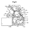
- a part of the coin guide rail 129 near the opening 106 is formed in a knife-shaped coin receiving portion 127 (see Figs. 5 and 6 etc.) for easy reception of the coin 110.
- the thicknesses of the coin guide rail 129 and coin receiving portion 127 are set to be enough for coins.
- the coins 110 accumulated inside the storage bowl 104 are stirred by the rotation disk 105 having the above structure and the coins 110 are held in the division recessed portion 113 one by one and moved upward, and are pushed out in the periphery direction from the division recessed portion 113 by the moving body 117 when the coin reaches the predetermined position upper than the rotation center.
- the pushed coins 110 lead to the opening 106 via the coin receiving portion 127.
- the coins are fed into the coin type determining apparatus 102 while rotating along the guide rail 129 by a feeding arm of the wheel 128 at the side of the coin type determining apparatus 102 rotating to face the opening 106, and then are fed into the carrying apparatus 104 after the coin type determination.
- the coin 110 is fed from the opening 106 to a coin passage 130 at the side of the coin type determining apparatus 102 by the rotation disk 105 in the same posture as the obliquely-provided rotation disk 105, and is received by the coin receiving portion 127.
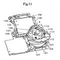
- the opening 106 is provided at an obliquely-cut portion at the lower right corner of the box-shaped coin type determining apparatus 102 as understood from Figs. 2 and 11 .
- the coin type determining apparatus 102 accommodates the wheel 128 in the circular recessed portion 126, and is composed of a plate-shaped fixed substrate 133 below the coin guide rail 129 and coin receiving portion 127 and a main body 134 which is pivoted at an attachment shaft 135 right to the fixed substrate 133 in an openable/closable manner, has a box-shaped case and incorporates a coin type determining sensor or the like inside the case.
- part of the periphery of the circular recessed portion 126 formed in the fixed substrate 133 is opened and is communicated with a recessed portion 109 inside the coin feeding apparatus 101 (see Fig. 5 ).
- the inner bottom face of the circular recessed portion 126 is a wheel-arranged base face 126S and the inner bottom face of the recessed portion 109 inside the apparatus is an upper face 105S of the rotation disk.
- the wheel-arranged base face 126S and the upper face 105S of the rotation disk are continuous in the plane.
- the inner bottom face of the circular recessed portion 126 as the coin feeding face and the inner bottom face of the recessed portion 109 inside the apparatus are continuous in the smooth plane so that a coin can be smoothly moved from the coin feeding apparatus 101 to the coin type determining apparatus 102 through the opening 106.
- the rear face 134B of the main body 134 is opposed to the wheel-arranged base face 126S as the inner bottom face of the circular recessed portion 126, and is also opposed to the upper face 105S of the rotation disk as the inner bottom face of the recessed portion 109 inside the apparatus.
- the opening 106 is formed among the three members.
- the opening 106 is in a slit shape, and the thickness and width thereof is set so that one coin to be fed can pass. Since the coin feeding apparatus copes with several types of coins, the opening 106 is set and formed to have the thickness and width in as much conformity as possible to a coin having the maximum thickness and maximum diameter.
- the opening 106 is a rectangular port surrounded by 4 members such as the coin receiving portion 127 for defining the thickness and width of the opening 106 and the right-side protrusion 140 (see Figs. 6 and 9 ) at the circular recessed portion opposite thereto in addition to the rear face 134B of the main body, the circular recessed portion 126 and the recessed portion 109 inside the apparatus.
- the surface of the wheel 128 is covered with the rear face 134B of the closed main body.
- an attachment plate 8 in a horizontally-long plate shape as shown in Fig. 11 is mounted in a canopy shape at the lower end of the main body 134 of the coin type determining apparatus 102.
- the canopy-shaped attachment plate 8 is opposed to the wheel-arranged base face 126S and the disk face 105S of the rotation disk when the main body 134 is closed, and constitutes part of the opening as the upper wall of the opening 106.
- the feeding operation may not be normally performed in some cases.
- a phenomenon as shown in Fig. 12 may occur.
- the coin 110 may drop off a tip end 117e of the moving body 117 due to apparatus's vibration or the like. If the coin 110 often drops off when the coin 110 is captured by the moving body 117 and is smoothly ready to be fed into the opening 106, the coin feeding rate decreases so that the apparatus lacks in its coin processing ability.
- the coin may drop off the coin receiving portion 127 or may be held at the tip end 127e of the coin receiving portion 127 in a hung manner instead of dropping off completely.
- the wheel 128 cannot rotate due to the stopped coin 110 and cannot feed out the coin 110 with its arm. Consequently, the wheel 128 cannot rotate, which is determined as the operation failure to interrupt the operation of the apparatus itself.
- the coin 110B stopping at the inlet of the opening 106 is sandwiched and locked between the opening 106 and the moving body 117 and thus cannot move because the coin is pressed at its opposite side with the moving body 117. Because of the thus locked coin 110B, the rotation disk 105 cannot rotate, which causes abnormal stop to the apparatus. The recover of the apparatus in the abnormal stop needs removal of the clogged coin 110B or the like, and consequently the working rate of the coin processing apparatus will decrease.
- the attachment plate 8 having a horizontally-long plate shape, which extends in a canopy shape as described above, is attached at the lower end of the main body 134 of the coin type determining apparatus 102.
- the pressing member 10 for elastically pressing the coin 110 against the upper face 105S of the rotation disk 105 is provided along the rotation path near the opening 106 of the rotation disk 105.
- the face opposite to the pressing face, that is the lower face of the coin 110 is pushed against the upper face 105S of the rotation disk 105 by the pressing member 10 by way of an appropriate pressing force.
- the pressing member 10 is a flexibly elastic plate which is configured to be made of synthetic resin or the like, to have a plane shape as shown in Fig. 3 and to have an oblique portion 12 as shown in Fig. 4 at its part.
- the pressing member 10 is mounted on the rear side of the attachment plate 8 by gluing. The glued portion is illustrated by diagonal lines 22.
- the pressing member 10 can be made of synthetic resin such as polycarbonate material having the thickness of 0.3 mm. Since the pressing member 10 is made of a flexible material such as synthetic resin, the material itself has appropriate elasticity.
- the pressing member 10 has a plate-shaped base 10k having a predetermined width and length, and the aforementioned oblique portion 12 is integrally formed with the plate-shaped base 10k at its one end at a predetermined inclination angle, for example at the inclination angle of 30°.
- the oblique portion 12 has a first pressing portion 14 which extends downward from the base 10k.
- the first pressing portion 14 is a first elastic pressing piece 14H.
- the oblique portion 12 is formed with a block plate 15 (described later) which is continuous with the first pressing portion 14 in the plane and extends upward from the base 10k.
- the block plate 15 is directed for preventing the coin 110 from proceeding toward the opening 106, which will be described later.
- the pressing member 10 comprises a second pressing portion 16 provided at the other end at a predetermined inclination angle, for example at the inclination angle of 30°.
- the second pressing portion 16 is a second elastic pressing piece 16H.
- the first elastic pressing piece 14H is configured to elastically contact with the upper face of the coin 110 at its tip end as shown in Fig. 4 .
- the first elastic pressing piece 14H is provided above the upper face 105S of the rotation disk 105 at the attachment height d such that the tip end thereof is slightly lower than the thickness D of the coin.
- the second elastic pressing piece 16H is also provided above the upper face 105S of the rotation disk 105 at the attachment height d such that the tip end thereof is slightly lower than the thickness D of the coin.
- the attachment height d is set at a position lower than the thickness D of the thinnest coin.
- each elastic pressing piece 14H, 16H presses the coin 110 against the upper face 105S of the rotation disk 105 by a repulsive force according to the amount of deflection of the tip end deflected by the coin, respectively.
- the pressing member 10 is configured such that the first pressing portion 14 (first elastic pressing piece 14H) is positioned before the opening 106, the second pressing portion 16 (second elastic pressing piece 16H) is positioned behind the opening 106, and the first and second pressing portions 14, 16 contact with the coin 110 moved by the moving body 117 at a good timing.
- the first elastic pressing piece 14H of the pressing member 10 contacts with the coin 110 put on the tip end of the moving body 117 at a good timing as shown in Figs. 5 and 6 and presses the same. Therefore, the coin 110 stably lies on the upper face 105S of the rotation disk 105 so that the coin 110 can be smoothly moved by the moving body 117.
- the coin 110 can be stably pressed so as not to separate from the upper face 105S of the rotation disk 105, the coin 110 is prevented from unstably moving in the thickness direction of the moving body 117 and is stably placed. Until the final stage where the moving body 117 pivotally operates and pushes the coin 110 from the division recessed portion 113, the coin 110 can be held without dropping off the moving body 117, thereby accurately feeding the coin 110. Thus, the coin feeding rate is improved.
- the pressing force by the pressing member 10 can be changed depending on the selection of a material of the pressing member 10, the inclination angle of the elastic pressing pieces 14H, 16H and the providing height, and it is possible to obtain an appropriate pressing force as needed by freely setting the conditions.
- both the first elastic pressing piece 14H and the second elastic pressing piece 16H are set at the inclination angle of 30°, but may be at a different angle. A portion where the first pressing portion 14 presses the coin 110 is pressed at the lower half of the coin face from the center of the coin 110 where a centrifugal force works less.
- the second pressing portion 16 is a triangle plate-shaped bending portion which is bent to be inclined downward toward the upper face 105S of the rotation disk 105 at a position opposite to the first pressing portion 12.
- the second elastic pressing piece 16H as this bending portion presses the coin 110 downward, that is toward the upper face 105S of the rotation disk.
- the second pressing portion 16 is positioned in opposite to the coin receiving portion 127 as shown in Figs. 7 and 8 .
- the coin 110 when the rotation disk 105 rotates and the coin 110 is put on the coin receiving portion 127 by the pivot operation of the moving body 117, the coin 110 is pressed against the upper face 105S of the rotation disk at an appropriate pressure by the second elastic pressing piece 16H of the second pressing portion 16 at a good timing as shown in Figs. 7 and 8 .
- the coin 110 can be stably received at the coin receiving portion 127 and remains placed on the coin receiving portion 127 stably after the receiving.
- the coin will not drop off the coin receiving portion 127.
- the coin 110 put on the coin receiving portion 127 is smoothly fed into the coin type determining apparatus 102 by the arm 128a of the wheel 128 which rotates and reaches the position.
- the coin When there is no pressing means for making the coin receiving state stable, the coin may drop off the coin receiving portion or may be hung in the dropped state.
- the coin stops on the way in the coin receiving portion 127 instead of dropping off completely the wheel 128 is stopped due to the coin and cannot rotate, and consequently the apparatus is in abnormal stop.
- the coin 110 since the coin 110 is passed to the coin receiving portion 127 in a more stable posture by the second pressing portion 16, the coin 110 will not stop at the coin receiving portion 127 in a hung manner so that the above failures are eliminated.
- the block plate 15 which is provided in the oblique portion 14 of the pressing member 10 and is inclined upward integrally with the first elastic pressing piece 14H.
- the block plate 15 is an elastic plate inclined upward relative to the upper face 105S of the rotation disk 105 toward the upstream side of the rotation direction of the rotation disk 105 and is formed continuously with the first pressing portion 12 as shown in Figs. 3, 4 , 5 and Figs. 9 , 10 .
- the inclination angle of the block plate 15 is 30°, which is the same as the first elastic pressing piece 14H.
- the block plate 15 has a necessary width, extends for a predetermined length in the diameter direction of the rotation disk 105, and thus extends near the opening 106.
- the block plate 15 which covers the rotation disk 105 like a roof before the opening 106, even when the coin 110 proceeds toward the inlet of the opening 106, the block plate 15 prevents it.
- the coin 110 is prevented from striking the opening 106 unlike a conventional coin 110B.
- the block plate 15 is present like a barrier provided in an upward-inclined manner relative to the upper face 105S of the rotation disk 105, even if the coin may jump from the disk face 105S due to apparatus's vibration, the coin is restricted from jumping by the block plate 15 and is prevented from falling out, and consequently will not strike the opening 106.
- the pressing member 10 Since the pressing member 10 is made of a flexible member such as synthetic resin, it has an elastic force and operates to return the coin 110 toward the upper face 105S of the disk by an appropriate pressure even when the coin 110 bounces and strikes the block plate 15 so that the blocking function on the coin works well.
- the present invention can easily and accurately eliminate failures such as the lock phenomenon at the coin feeding port, the coin dropping-off phenomenon from the moving body, the rotation disability of the rotation disk due to coin stop at the coin receiving portion and the like by providing the coin pressing member 10 described above.
- the coin feeding operation of the coins can be stably performed, the coin processing rate of the entire apparatus is remarkably improved, thereby obtaining a beneficial coin feeding apparatus.
Description
- The present invention relates to a coin feeding apparatus for holding many coins accommodated in a storage portion in their division recessed portion by a rotation disk one by one, and feeding the coins from a feed-out port to a next step portion, for example, a coin identification apparatus or the like via a coin receiving portion at the outer periphery. It particularly relates to a coin feeding apparatus suitable for stably and accurately paying coins moved and fed out along the outer periphery of the rotation disk by way of a centrifugal force.
The term "coin" used herein in the specification includes currency coins, tokens, medals and the like, and includes circular ones and polygonal ones in its shape. - As one conventional technique of a coin feeding apparatus, there has been known a coin processing apparatus in which a rotation disk is provided inside a hopper and coins are scraped out one by one by a claw provided on the rotation disk to be moved upward and are received in a coin rail at the exit near the top portion to be guided to a coin mechanism from the exit along the rail. (See Patent Literature 1, for example).
- In
EP 1 617 384 a coin feeding apparatus is disclosed which holds coins in sorting concave portions arranged in an upper surface of a rotary disk. Each of the concave portions is provided with a moving member movable in a diametrical direction of the rotary disk. Thereby the moving member is moved in the diametrical direction when the coin is transferred to the coin conveyer. - [Patent Literature 1]
Japanese Patent Application Laid-Open No. 2000-298749 - In such a conventional technique, a coin can drop off the claw due to vibration of the apparatus itself occurring when the coin is supplied and thrown into a hopper while the coin is being subjected to feeding operation to the exit by the rotation disk.
Particularly a coin having a small diameter and thin thickness can easily drop off. Although such a coin is scraped out and is in the feeding operation, if the coin drops off, the feeding operation comes to nothing, which undesirably reduces the coin processing efficiency.
Further, at the time of the normal coin feeding by the rotation disk, the coin is pushed out while being moved in the periphery direction on the disk face of the rotation disk, and enters the slit-shaped exit in parallel, which has no problem. The height and width of the exit formed in a slit shape is set such that a horizontally-laid coin, that is only one coin laid on the upper face of the rotation circular plate can pass through.
If a coin drops off the disk face of the rotation disk due to vibration or the like of the apparatus during the coin feeding, the coin can unintentionally strike the slit-shaped exit obliquely.
Then, the coin which obliquely strikes the exit is pressed with the claw in the feeding operation on its opposite side, and consequently the coin is sandwiched between the exit and the claw to be in the lock state.
In such a situation, the rotation disk cannot perform feeding rotation due to the locked coin so that the rotation is stopped. The rotation stop is detected as an operation fault and the entire apparatus is stopped in its operation by the controller so that a complicated work such as removal of the locked coin is needed for recovery. Therefore, there is a problem that a frequent abnormal stop due to such a cause also reduces the operation rate of the coin feeding apparatus.
Furthermore, when a coin carried near the exit is passed to a coin rail by the rotation disk, the coin can drop off the rail due to unstable swing caused by vibration of the apparatus itself. The coin can drop off due to irregular motion of the coin itself stirred and rotated at a fast speed inside the hopper instead of being put on the rail.
The coin may not drop off and the coin may be hung and stopped at the rail.
In this case, when the coin passed to the receiving portion is fed out by a feeding wheel, the wheel pressed against the coin cannot rotate due to the stopped coin so that the apparatus will be stopped in its operation.
With such a problem, while the rotation disk captures the coin by the coin feeding member such as the rotation claw and feeds it to the exit, it is important for improving the coin processing efficiency and obtaining the coin feeding apparatus with excellent performance to stably carry the coin so as not to cause coin drop-off or lock state. - The present invention has been made in terms of the above problems and it is a first object to provide a coin feeding apparatus capable of efficiently processing a coin and maintaining and carrying the coin in a more stable state when the coin is being fed by a rotation disk.
Further, it is a second object to provide a coin feeding apparatus in which a coin can be stably carried with a simple structure and at low cost. - These objects are solved by a device according to claim 1. Further advantageous developments are subject-matter of the dependent claims.
In order to achieve the objects, a coin processing apparatus according to a first aspect is configured as follows.
In a coin feeding apparatus configured such that after coins are held and divided into a division recessed portion arranged on the upper face of a rotation disk, the coins are fed out from an opening provided at a predetermined position in the periphery direction of the rotation disk toward a next step by a coin pushing moving body movably provided in the division recessed portions, there is configured such that when the coins are moved in the periphery direction of the rotation disk by the moving body at the time of the rotation of the rotation disk, a pressing member for elastically pressing the coins against the upper face of the rotation disk is provided. - In this structure, when the rotation disk rotates, the moving body operates in association therewith to push the coin outward and feed it to the opening as an exit while moving the coin in the periphery direction.
At that time, the coin is being pressed against the upper face of the rotation disk by the coin pressing portion. The coin stably lies on the upper face of the rotation disk and is stably put on the moving body. Thus, during the coin feeding operation by the moving body, the coin will not drop off the moving body. Thus, the coin temporarily held by the moving body is certainly fed to the opening so that a lean processing is performed, thereby improving the coin processing rate. It is possible to provide a coin feeding apparatus with high operation reliability and remarkably less failures. - According to a second aspect, there is provided a coin feeding apparatus according to the first aspect wherein the pressing member is provided with a first pressing portion for elastically pressing coins moved from the division recessed portion in the periphery direction of the rotation disk by the moving body against the upper face of the rotation disk, and a second pressing portion for pressing the coins immediately before being passed by the moving body to a coin receiving portion provided near the opening against the upper face of the rotation disk.
With this structure, when the coin in the initial operation of the moving body is pushed outside the division recessed portion, the coin is in a pressed state onto the upper face of the rotation disk by the first pressing portion. Thus, since the coin lies on the upper face of the rotation disk in a more stable state, the coin will not drop off the moving body, thereby accurately pushing the coin.
Also when the coin is passed to the coin receiving portion by a further operation of the moving body, the coin is pressed onto the upper face of the disk by the second pressing portion to be stable in its posture so that the coin can be smoothly passed to the coin receiving portion.
Since the coin remains pressed onto the upper face of the rotation disk even after being passed, the coin is stably put on the coin receiving portion until the feeding rotation wheel reaches. Therefore, the coins can be accurately fed out one by one by the coin feeding wheel.
Particularly, since there is eliminated a situation where the coin stops in the coin receiving portion in a hung manner, there can be prevented unlike conventionally a trouble where the coin feeding wheel cannot rotate due to the hung coin so that the coin feeding apparatus failed. Thus, it is possible to accurately feed the coin without a failure. - According to a third aspect, there is provided a coin feeding apparatus according to the second aspect comprising a block plate inclined upward relative to the upper face of the rotation disk toward the rotation upstream direction of the rotation disk, for preventing the coins moved in the periphery direction of the rotation disk from proceeding toward the inlet of the opening, which is provided continuously with the first pressing portion and extends in the diameter direction of the rotation disk.
With this structure, even when the coin moves to strike the opening as the feeding portion during the coin feeding operation, the movement thereof is stopped by the block plate inclined upward before the opening so that the coin will not strike the inlet of the opening.
Therefore, there can be prevented unlike conventionally the occurrence where the coin strikes the opening and is sandwiched between the opening and the moving body to be in the lock state.
In this manner, there are less failures in which the coin is locked during the feeding and consequently the rotation disk cannot rotate, thereby obtaining the coin feeding apparatus with high reliability which can be normally operated for a long time. - According to a fourth aspect, there is provided a coin feeding apparatus according to the first to third aspects, wherein the pressing member is an elastic pressing plate integrally composed of a first elastic pressing piece which is inclined downward and extends so as to be positioned before the opening and contact with the coins on the rotation disk at its tip end and a second elastic pressing piece which is inclined downward and extends so as to be positioned behind the opening and contact with the coins on the rotation disk at its tip end.
With this structure, since the first elastic pressing piece is positioned before the opening where the moving body operates to push the coin outside the division recessed portion at a good timing, the coin can be effectively pushed out. Further, since the second elastic pressing piece is positioned behind the opening where the moving body operates to pass the coin to the coin receiving portion at a good timing, the coin can be effectively fed into the opening.
Further, there is used an elastic pressing plate in which the first elastic pressing piece and the second elastic pressing piece are integrally formed before and behind the opening so that the coin can be stably fed out with a simple structure. Further, since the elastic pressing plate can be made of synthetic resin, it can be provided with simple and inexpensive member, which is so practical. - In a coin feeding apparatus configured such that after coins are held and divided into a division recessed portion arranged on the upper face of a rotation disk, the coins are fed out from an opening with a coin receiving portion provided at a predetermined position in the periphery direction of the rotation disk by a coin pushing moving body movably provided in the division recessed portions, there is configured such that when the coins are pushed outside the division recessed portion by the rotation disk and moved to the opening, a pressing member for elastically pressing the coins against the upper face of the rotation disk is provided so that the coin can be stably moved onto the upper face of the disk, thereby stably and accurately processing the coins.
- Hereinafter, an embodiment according to the present invention will be described with reference to the drawings.
-
Fig. 1 is a schematic front view of a coin processing apparatus using a coin feeding apparatus according to the embodiment of the present invention. -
Fig. 2 is a front view of the coin feeding apparatus according to the embodiment of the present invention. -
Fig. 3 is a front view of a coin pressing member provided in the coin feeding apparatus according to the present invention. -
Fig. 4 is a bottom view of the pressing member. -
Figs. 5 to 10 show specific examples showing the operations of the coin feeding apparatus according to the embodiment of the present inventionFig. 5 is a front view showing how coin drop-off is eliminated by the coin feeding apparatus according to the embodiment of the present invention andFig. 6 is a perspective view of an appearance thereof.Figs. 7 and8 are a front view and appearance perspective view showing how a coin receiving mistake is eliminated by the coin feeding apparatus according to the embodiment of the present invention.Figs. 9 and10 are a front view and appearance perspective view showing how a coin lock state at an opening (coin feeding port) is eliminated by the coin feeding apparatus according to the embodiment of the present invention. -
Fig. 11 is a perspective view of the entire appearance schematically showing a structure of the coin feeding apparatus according to the present invention. -
Figs. 12 to 15 are views showing various failures at the time of coin feeding by an unimproved coin feeding apparatus according to the present invention, whereFig. 12 is a front view showing a coin drop-off phenomenon.Fig. 13 is a front view showing a coin receiving mistake phenomenon.Fig. 14 is a front view showing a phenomenon when a coin is locked and temporarily stopped, andFig. 15 is a cross-sectional view taken along the line A-A ofFig. 14 . - At first, the structure of the coin feeding apparatus according to the present invention will be described with reference to
Figs. 1 to 11 .
The present embodiment is a coin feeding apparatus in a coin processing apparatus which receives 8 types of coins such as 2-euro coin, 1-euro coin, 50-cent coin, 20-cent coin, 10-cent coin, 5-cent coin, 2-cent coin and 1-cent coin, which are common currency of the European Union, and stores the same for each type, and pays the predetermined numbers of coins of predetermined types based on payment instruction.
InFig. 1 , thecoin processing apparatus 100 includes acoin feeding apparatus 101, a cointype determining apparatus 102, a coin carrying apparatus 103 and a coin selecting apparatus (not shown) provided inside the coin carrying apparatus 103.
In other words, thecoin feeding apparatus 100 is provided with arotation disk 105 for dividing and feeding coins one by one and the coins are fed to the cointype determining apparatus 102 one by one by a movingbody 117 pivotably provided on therotation disk 105. Acoin 110 is fed into the cointype determining apparatus 102 through acoin passing opening 106 provided at the top of thecoin feeding apparatus 101. - The present invention is characterized in that the
coin 110 is pushed in the outer periphery direction of the disk by way of the rotation operation of therotation disk 105 in thecoin feeding apparatus 101 and fed into theopening 106 at the top thereof while being moved along the outer periphery of the disk and that a pressingmember 10 for pressing thecoin 110 against theupper face 105S of therotation disk 105 is provided so that the coin feeding operation can be stably performed.
The pressingmember 10 is arranged along the rotation path of therotation disk 105 around theopening 106. While thecoin 110 is being carried from thecoin feeding apparatus 101 to the cointype determining apparatus 102, the coin neither drops off the movingbody 117 nor becomes jammed along the moving path, and is accurately fed into theopening 106 so that the coins can be efficiently processed. Details thereof will be described later. - After the authenticity and type of coins are determined by a magnetic sensor or the like (not shown) in the coin
type determining apparatus 102, the coins are fed into the carrying apparatus 103 for the next step, and the coins are separated based on the type in the coin selecting apparatus configured to open/close a predetermined gate while being carried along the predetermined path.
For more detailed description, thecoin feeding apparatus 100 includes arotation disk 105, astorage bowl 104 for storing coins, and a cylinder-shapedstorage ring 107 positioned under thestorage bowl 104 to surround therotation disk 105. Several types of coins thrown from the coin throwing port are introduced and drops into the storage portion under the release port of thestorage bowl 104 to be stored in an accumulated manner. - The
rotation disk 105 has a division recessedportion 113 for receiving coins one by one, is obliquely provided at the bottom of thestorage ring 107 at a predetermined angel and is rotated at a predetermined speed and in a certain direction that is counterclockwise as shown by an arrow G in the embodiment.
Therotation disk 105 is composed of a base rotationcircular plate 111 and a pushingdisk 112 fixed on the upper face of the rotationcircular plate 111 coaxially with the rotationcircular plate 111 and made of a Y-shaped plate having three recessed portions at a constant interval on theprotrusion 115 so that a space between theprotrusions 115 of the pushingdisk 112 and the movingbody 117 described later form a substantially semicircular division recessedportion 113 at the upper face of the rotationcircular plate 111.
Further, the depth of the division recessedportion 113 that is the thickness of the pushingdisk 112 is formed to be slightly smaller than the thickness of the thinnest coin among the 8 types of coins.
The plate is not limited to the Y-shape and may be a plate in which several protrusions are radially formed. The rotationcircular plate 111 and the plate that is the pushingdisk 112 may be integrally shaped by pre-sintered metal or wear-resistant resin. - The division recessed
portion 113 between theprotrusions 115 has the movingbody 117 arranged at its one side, which pivotally operates about apivot shaft 120.
The division recessedportion 113 is formed to be a substantially semicircular division recessed portion on the rotationcircular plate 111 by the movingbody 117 and theprotrusions 115. A slightly concaved recessed portion is formed at the other side of the division recessedportion 113 in theprotrusion 115 and a coinextrusive portion 121 for receiving thecoin 110 against the recessed portion and carrying the same is formed in the recessed portion. An arcuate receivingportion 118 for receiving the movingbody 117 is provided in the division recessedportion 113 in opposite to the coinextrusive portion 121.
Here, the division recessedportion 113 is set in its size such that two coins having the smallest diameter cannot be received side by side and only one coin having the largest diameter can be received.
Thus, two coins having the smallest diameter cannot be received into the division recessedportion 113 side by side in the diameter direction of therotation disk 105. - When the moving
body 117 is typically in the rest state near one side of the recessed portion so as to form the division recessedportion 113 and is moved to a predetermined position through the pivot motion, the movingbody 117 feeds the stored coins in the periphery direction of the rotationcircular plate 111.
The movement to the predetermined position by the movingbody 117 is performed along the rotation path of therotation disk 105 slightly downstream the aforementionedcoin passing opening 106 which is formed such that the coin can pass to the cointype determining apparatus 102 at the top of thestorage ring 107. When the movingbody 117 passes through theopening 106, the movingbody 117 is returned and operated to be accommodated in the receivingportion 118 formed at one side of the recessed portion.
The movingbody 117 can be moved on a groove cam by utilizing the rotation operation of the rotationcircular plate 111. In other words, apin 122 is fixedly provided at the middle of the movingbody 117 and is inserted into an arcuate throughhole 123 formed about thepivot shaft 120, where thepin 122 is formed in the rotationcircular plate 111 of therotation disk 105. Further, there may be employed a drive mechanism in which thepin 122 is slidably inserted into the groove cam provided at the lower side of the rotation circular plate 111 (not shown) through a moved body such as roller.
Therotation disk 105 is rotated by an electric motor 124 (seeFig. 1 ) . The rotation of theelectric motor 124 is transmitted to a deceleration gear (not shown) formed at the lower periphery face of the rotation circular plate 111 (not shown) through a decelerator and therotation disk 105 is rotated at a predetermined speed. - On the other hand, a
coin feeding wheel 128 is provided at the side of the cointype determining apparatus 102 into which a coin is fed. Acoin guide rail 129 is provided inside the cointype determining apparatus 102 in correspondence to thewheel 128.
A part of thecoin guide rail 129 near theopening 106 is formed in a knife-shaped coin receiving portion 127 (seeFigs. 5 and6 etc.) for easy reception of thecoin 110. The thicknesses of thecoin guide rail 129 andcoin receiving portion 127 are set to be enough for coins. - Thus, the
coins 110 accumulated inside thestorage bowl 104 are stirred by therotation disk 105 having the above structure and thecoins 110 are held in the division recessedportion 113 one by one and moved upward, and are pushed out in the periphery direction from the division recessedportion 113 by the movingbody 117 when the coin reaches the predetermined position upper than the rotation center.
The pushedcoins 110 lead to theopening 106 via thecoin receiving portion 127. Then, the coins are fed into the cointype determining apparatus 102 while rotating along theguide rail 129 by a feeding arm of thewheel 128 at the side of the cointype determining apparatus 102 rotating to face theopening 106, and then are fed into the carryingapparatus 104 after the coin type determination.
In this manner, thecoin 110 is fed from theopening 106 to acoin passage 130 at the side of the cointype determining apparatus 102 by therotation disk 105 in the same posture as the obliquely-providedrotation disk 105, and is received by thecoin receiving portion 127. Theopening 106 is provided at an obliquely-cut portion at the lower right corner of the box-shaped cointype determining apparatus 102 as understood fromFigs. 2 and11 . - For further description of the coin
type determining apparatus 102, the cointype determining apparatus 102 accommodates thewheel 128 in the circular recessedportion 126, and is composed of a plate-shaped fixedsubstrate 133 below thecoin guide rail 129 andcoin receiving portion 127 and amain body 134 which is pivoted at anattachment shaft 135 right to the fixedsubstrate 133 in an openable/closable manner, has a box-shaped case and incorporates a coin type determining sensor or the like inside the case.
Here, part of the periphery of the circular recessedportion 126 formed in the fixedsubstrate 133 is opened and is communicated with a recessedportion 109 inside the coin feeding apparatus 101 (seeFig. 5 ).
The inner bottom face of the circular recessedportion 126 is a wheel-arrangedbase face 126S and the inner bottom face of the recessedportion 109 inside the apparatus is anupper face 105S of the rotation disk. The wheel-arrangedbase face 126S and theupper face 105S of the rotation disk are continuous in the plane. Thus, the inner bottom face of the circular recessedportion 126 as the coin feeding face and the inner bottom face of the recessedportion 109 inside the apparatus are continuous in the smooth plane so that a coin can be smoothly moved from thecoin feeding apparatus 101 to the cointype determining apparatus 102 through theopening 106. - When the
main body 134 of the cointype determining apparatus 102 is closed, as shown inFig. 15 , therear face 134B of themain body 134 is opposed to the wheel-arrangedbase face 126S as the inner bottom face of the circular recessedportion 126, and is also opposed to theupper face 105S of the rotation disk as the inner bottom face of the recessedportion 109 inside the apparatus. Thus, theopening 106 is formed among the three members.
Theopening 106 is in a slit shape, and the thickness and width thereof is set so that one coin to be fed can pass. Since the coin feeding apparatus copes with several types of coins, theopening 106 is set and formed to have the thickness and width in as much conformity as possible to a coin having the maximum thickness and maximum diameter.
For detailed description, theopening 106 is a rectangular port surrounded by 4 members such as thecoin receiving portion 127 for defining the thickness and width of theopening 106 and the right-side protrusion 140 (seeFigs. 6 and9 ) at the circular recessed portion opposite thereto in addition to therear face 134B of the main body, the circular recessedportion 126 and the recessedportion 109 inside the apparatus. The surface of thewheel 128 is covered with therear face 134B of the closed main body. - At the
opening 106, anattachment plate 8 in a horizontally-long plate shape as shown inFig. 11 is mounted in a canopy shape at the lower end of themain body 134 of the cointype determining apparatus 102.
The canopy-shapedattachment plate 8 is opposed to the wheel-arrangedbase face 126S and thedisk face 105S of the rotation disk when themain body 134 is closed, and constitutes part of the opening as the upper wall of theopening 106. - When the
rotation disk 105 is rotated, and thecoin 110 is pushed outside the division recessedportion 113 by the movingbody 117 which pivotally operates in accordance with the rotation, and is fed toward theopening 106 while being moved along the inner periphery of thestorage bowl 104, the feeding operation may not be normally performed in some cases.
For example, a phenomenon as shown inFig. 12 may occur.
In other words, when thecoin 110 is pushed out from the division recessedportion 113 by the movingbody 117, thecoin 110 may drop off atip end 117e of the movingbody 117 due to apparatus's vibration or the like. If thecoin 110 often drops off when thecoin 110 is captured by the movingbody 117 and is smoothly ready to be fed into theopening 106, the coin feeding rate decreases so that the apparatus lacks in its coin processing ability. - As shown in
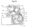
Fig. 13 , at the final stage where thecoin 110 is put on thecoin receiving portion 127 by the movingbody 117, the coin may drop off thecoin receiving portion 127 or may be held at thetip end 127e of thecoin receiving portion 127 in a hung manner instead of dropping off completely.
When thecoin 110 is not put on the receivingportion 127 and is stopped at the receivingportion 127 in a hung manner, thewheel 128 cannot rotate due to the stoppedcoin 110 and cannot feed out thecoin 110 with its arm. Consequently, thewheel 128 cannot rotate, which is determined as the operation failure to interrupt the operation of the apparatus itself. - Moreover, as shown in
Figs. 14 and15 , when thecoins 110 are moved from the division recessedportion 113 to the outer periphery by the movingbody 117, somecoins 110 jump out from the disk face of therotation disk 105 due to apparatus's vibration, and other coins directs outside therotation disk 105 due to momentum. Then, the coins may strike the inlet of theopening 106 like acoin 110B as shown inFig. 15 . In other words, thecoin 110B becomes oblique and strikes thetip end 8d of theattachment plate 8 at itsupper end 110g and stops at theopening 106. Thecoin 110B stopping at the inlet of theopening 106 is sandwiched and locked between theopening 106 and the movingbody 117 and thus cannot move because the coin is pressed at its opposite side with the movingbody 117.
Because of the thus lockedcoin 110B, therotation disk 105 cannot rotate, which causes abnormal stop to the apparatus.
The recover of the apparatus in the abnormal stop needs removal of the cloggedcoin 110B or the like, and consequently the working rate of the coin processing apparatus will decrease. - The present invention has been improved so as not to cause such a trouble. At first, the
attachment plate 8 having a horizontally-long plate shape, which extends in a canopy shape as described above, is attached at the lower end of themain body 134 of the cointype determining apparatus 102.
On the other hand, as shown inFigs. 2 to 10 and the like, the pressingmember 10 for elastically pressing thecoin 110 against theupper face 105S of therotation disk 105 is provided along the rotation path near theopening 106 of therotation disk 105.
The face opposite to the pressing face, that is the lower face of thecoin 110 is pushed against theupper face 105S of therotation disk 105 by the pressingmember 10 by way of an appropriate pressing force. Thus, thecoin 110 stably lies on the upper face of therotation disk 105. In this manner, since the coin can be placed on theupper face 105S of therotation disk 105 in a stable posture, thecoin 110 can be smoothly fed out.
The pressingmember 10 is a flexibly elastic plate which is configured to be made of synthetic resin or the like, to have a plane shape as shown inFig. 3 and to have anoblique portion 12 as shown inFig. 4 at its part.
The pressingmember 10 is mounted on the rear side of theattachment plate 8 by gluing. The glued portion is illustrated bydiagonal lines 22. The pressingmember 10 can be made of synthetic resin such as polycarbonate material having the thickness of 0.3 mm.
Since the pressingmember 10 is made of a flexible material such as synthetic resin, the material itself has appropriate elasticity. - With more detailed description, the pressing
member 10 has a plate-shapedbase 10k having a predetermined width and length, and theaforementioned oblique portion 12 is integrally formed with the plate-shapedbase 10k at its one end at a predetermined inclination angle, for example at the inclination angle of 30°.
Theoblique portion 12 has a firstpressing portion 14 which extends downward from thebase 10k. The firstpressing portion 14 is a first elasticpressing piece 14H.
Further, theoblique portion 12 is formed with a block plate 15 (described later) which is continuous with the first pressingportion 14 in the plane and extends upward from thebase 10k. Theblock plate 15 is directed for preventing thecoin 110 from proceeding toward theopening 106, which will be described later. - The pressing
member 10 comprises a secondpressing portion 16 provided at the other end at a predetermined inclination angle, for example at the inclination angle of 30°. The secondpressing portion 16 is a second elastic pressingpiece 16H. - The first elastic
pressing piece 14H is configured to elastically contact with the upper face of thecoin 110 at its tip end as shown inFig. 4 .
In other words, as illustrated in the figure, the first elasticpressing piece 14H is provided above theupper face 105S of therotation disk 105 at the attachment height d such that the tip end thereof is slightly lower than the thickness D of the coin.
Similarly, the second elastic pressingpiece 16H is also provided above theupper face 105S of therotation disk 105 at the attachment height d such that the tip end thereof is slightly lower than the thickness D of the coin.
In this case, since several types of coins are treated, the attachment height d is set at a position lower than the thickness D of the thinnest coin.
Thus, since the pressingmember 10 is provided such that the first and second elastic pressingpieces pressing piece coin 110 against theupper face 105S of therotation disk 105 by a repulsive force according to the amount of deflection of the tip end deflected by the coin, respectively. - The pressing
member 10 is configured such that the first pressing portion 14 (first elasticpressing piece 14H) is positioned before theopening 106, the second pressing portion 16 (second elastic pressingpiece 16H) is positioned behind theopening 106, and the first and secondpressing portions coin 110 moved by the movingbody 117 at a good timing.
Thus, when thecoin 110 is moved to the outer periphery side by the movingbody 117, the first elasticpressing piece 14H of the pressingmember 10 contacts with thecoin 110 put on the tip end of the movingbody 117 at a good timing as shown inFigs. 5 and6 and presses the same. Therefore, thecoin 110 stably lies on theupper face 105S of therotation disk 105 so that thecoin 110 can be smoothly moved by the movingbody 117.
In other words, since thecoin 110 can be stably pressed so as not to separate from theupper face 105S of therotation disk 105, thecoin 110 is prevented from unstably moving in the thickness direction of the movingbody 117 and is stably placed. Until the final stage where the movingbody 117 pivotally operates and pushes thecoin 110 from the division recessedportion 113, thecoin 110 can be held without dropping off the movingbody 117, thereby accurately feeding thecoin 110. Thus, the coin feeding rate is improved. - The pressing force by the pressing
member 10 can be changed depending on the selection of a material of the pressingmember 10, the inclination angle of the elasticpressing pieces
In the embodiment, both the first elasticpressing piece 14H and the second elastic pressingpiece 16H are set at the inclination angle of 30°, but may be at a different angle.
A portion where the first pressingportion 14 presses thecoin 110 is pressed at the lower half of the coin face from the center of thecoin 110 where a centrifugal force works less. This is because it is expected that if the upper half of the coin face at a farther position on the outer periphery from the rotation center of therotation disk 105 is pressed, the pressing force against the coin is unstable due to a centrifugal force so that the moving body cannot stably hold the coin. - When the
coin 110 is further carried and approaches theopening 106, the secondpressing portion 16 of the pressingmember 10 operates. The operation will be described below.
The secondpressing portion 16 is a triangle plate-shaped bending portion which is bent to be inclined downward toward theupper face 105S of therotation disk 105 at a position opposite to the first pressingportion 12. The second elastic pressingpiece 16H as this bending portion presses thecoin 110 downward, that is toward theupper face 105S of the rotation disk.
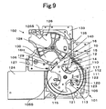
The secondpressing portion 16 is positioned in opposite to thecoin receiving portion 127 as shown inFigs. 7 and8 .
Therefore, when therotation disk 105 rotates and thecoin 110 is put on thecoin receiving portion 127 by the pivot operation of the movingbody 117, thecoin 110 is pressed against theupper face 105S of the rotation disk at an appropriate pressure by the second elastic pressingpiece 16H of the secondpressing portion 16 at a good timing as shown inFigs. 7 and8 .
Thus, thecoin 110 can be stably received at thecoin receiving portion 127 and remains placed on thecoin receiving portion 127 stably after the receiving. Thus, the coin will not drop off thecoin receiving portion 127.
Thecoin 110 put on thecoin receiving portion 127 is smoothly fed into the cointype determining apparatus 102 by the arm 128a of thewheel 128 which rotates and reaches the position.
When there is no pressing means for making the coin receiving state stable, the coin may drop off the coin receiving portion or may be hung in the dropped state.
When the coin stops on the way in thecoin receiving portion 127 instead of dropping off completely, thewheel 128 is stopped due to the coin and cannot rotate, and consequently the apparatus is in abnormal stop.
However, since thecoin 110 is passed to thecoin receiving portion 127 in a more stable posture by the secondpressing portion 16, thecoin 110 will not stop at thecoin receiving portion 127 in a hung manner so that the above failures are eliminated. - There will be below described the
block plate 15 which is provided in theoblique portion 14 of the pressingmember 10 and is inclined upward integrally with the first elasticpressing piece 14H.
Theblock plate 15 is an elastic plate inclined upward relative to theupper face 105S of therotation disk 105 toward the upstream side of the rotation direction of therotation disk 105 and is formed continuously with the first pressingportion 12 as shown inFigs. 3, 4 ,5 andFigs. 9 ,10 . The inclination angle of theblock plate 15 is 30°, which is the same as the first elasticpressing piece 14H. Theblock plate 15 has a necessary width, extends for a predetermined length in the diameter direction of therotation disk 105, and thus extends near theopening 106.
Therefore, when there is theblock plate 15 which covers therotation disk 105 like a roof before theopening 106, even when thecoin 110 proceeds toward the inlet of theopening 106, theblock plate 15 prevents it. Thus, thecoin 110 is prevented from striking theopening 106 unlike aconventional coin 110B.
Since theblock plate 15 is present like a barrier provided in an upward-inclined manner relative to theupper face 105S of therotation disk 105, even if the coin may jump from thedisk face 105S due to apparatus's vibration, the coin is restricted from jumping by theblock plate 15 and is prevented from falling out, and consequently will not strike theopening 106.
Since the pressingmember 10 is made of a flexible member such as synthetic resin, it has an elastic force and operates to return thecoin 110 toward theupper face 105S of the disk by an appropriate pressure even when thecoin 110 bounces and strikes theblock plate 15 so that the blocking function on the coin works well. - In this manner, there will not occur the lock state in which the coin striking the
opening 106 causes thecoin 110B to be sandwiched between the inlet of theopening 106 and the movingbody 117, which was a conventional problem as shown inFigs. 14 and15 .
Thus, since a failure such as rotation stop of therotation disk 105 is eliminated, the coin can be smoothly fed into the coin type determining apparatus at the next step, thereby obtaining the coin feeding apparatus capable of efficiently processing the coins. - The present invention can easily and accurately eliminate failures such as the lock phenomenon at the coin feeding port, the coin dropping-off phenomenon from the moving body, the rotation disability of the rotation disk due to coin stop at the coin receiving portion and the like by providing the
coin pressing member 10 described above.
Thus, since the coin feeding operation of the coins can be stably performed, the coin processing rate of the entire apparatus is remarkably improved, thereby obtaining a beneficial coin feeding apparatus.
Claims (4)
- A coin feeding apparatus configured such that after coins (110) are held and divided into division recessed portions (113) arranged on the upper face of a rotation disk (105), the coins (110) are fed out from an opening (106) provided at a predetermined position in the periphery direction of the rotation disk (105) by a coin pushing moving body (117) movably provided in the division recessed portions (113),
wherein when the coins (110) are moved in the periphery direction of the rotation disk (105) by the moving body (117) at the time of the rotation of the rotation disk (105), characterized in that a pressing member (10) for elastically pressing the coins (110) against the upper face of the rotation disk (105) is provided. - A coin feeding apparatus according to claim 1, wherein the pressing member (10) is provided with a first pressing portion (14) for elastically pressing coins (110) moved from the division recessed portion (113) in the periphery direction of the rotation disk (105) by the moving body (117) against the upper face of the rotation disk (105), and a second pressing portion (16) for pressing the coins (110) immediately before being passed by the moving body (117) to a coin receiving portion (127) provided near the opening (106) against the upper face of the rotation disk (105).
- A coin feeding apparatus according to claim 2, comprising a block plate (15) inclined upward relative to the upper face of the rotation disk toward the rotation upstream direction of the rotation disk, for preventing the coins (110) moved in the periphery direction of the rotation disk from proceeding toward the inlet of the opening (106), which is provided continuously with the first pressing portion (14) and extends in the diameter direction of the rotation disk (105).
- A coin feeding apparatus according to claims 1 to 3, wherein the pressing member (10) is an elastic pressing plate integrally composed of a first elastic pressing piece which is inclined downward and extends so as to be positioned before the opening (106) and contact with the coins (110) on the rotation disk (105) at its tip end and a second elastic pressing piece which is inclined downward and extends so as to be positioned behind the opening (106) and contact with the coins (110) on the rotation disk (105) at its tip end.
Applications Claiming Priority (1)
| Application Number | Priority Date | Filing Date | Title |
|---|---|---|---|
| JP2006297283A JP5109035B2 (en) | 2006-11-01 | 2006-11-01 | Coin feeding device |
Publications (2)
| Publication Number | Publication Date |
|---|---|
| EP1918888A1 EP1918888A1 (en) | 2008-05-07 |
| EP1918888B1 true EP1918888B1 (en) | 2011-07-13 |
Family
ID=38740331
Family Applications (1)
| Application Number | Title | Priority Date | Filing Date |
|---|---|---|---|
| EP07021333A Active EP1918888B1 (en) | 2006-11-01 | 2007-10-31 | Coin feeding apparatus |
Country Status (3)
| Country | Link |
|---|---|
| US (1) | US7666076B2 (en) |
| EP (1) | EP1918888B1 (en) |
| JP (1) | JP5109035B2 (en) |
Families Citing this family (12)
| Publication number | Priority date | Publication date | Assignee | Title |
|---|---|---|---|---|
| JP5716199B2 (en) * | 2011-03-17 | 2015-05-13 | 旭精工株式会社 | Coin separator / conveyor |
| JP5945773B2 (en) * | 2012-12-18 | 2016-07-05 | 旭精工株式会社 | Coin hopper |
| CN106157435B (en) * | 2015-04-10 | 2019-08-30 | 吉鸿电子股份有限公司 | The currency-pulling device of Coin dispensing apparatus |
| JP6402332B2 (en) * | 2015-09-09 | 2018-10-10 | 旭精工株式会社 | Coin hopper |
| CN106327669A (en) * | 2016-08-12 | 2017-01-11 | 深圳怡化电脑股份有限公司 | Money depositing and withdrawing device and money depositing and withdrawing equipment ATM and VTM |
| DK179422B1 (en) * | 2017-09-27 | 2018-06-18 | Ctcoin As | A coin separation mechanism and a coin processing apparatus comprising such a coin separation mechanism |
| US11721154B2 (en) * | 2017-10-10 | 2023-08-08 | Crane Payment Innovations, Inc. | Coin payout apparatus |
| JP6934677B2 (en) * | 2019-01-28 | 2021-09-15 | 旭精工株式会社 | Coin separation detector |
| JP6934676B2 (en) | 2019-01-28 | 2021-09-15 | 旭精工株式会社 | Coin separation and delivery device for coin processing equipment |
| JP6956418B2 (en) * | 2019-03-04 | 2021-11-02 | 旭精工株式会社 | Coin identification and transport device |
| US11527123B2 (en) * | 2019-10-07 | 2022-12-13 | Asahi Seiko Co., Ltd. | Coin delivery device and coin processing device |
| JP7193154B2 (en) * | 2020-03-09 | 2022-12-20 | 旭精工株式会社 | Coin sending device and coin processing device |
Family Cites Families (13)
| Publication number | Priority date | Publication date | Assignee | Title |
|---|---|---|---|---|
| US3191739A (en) * | 1959-03-09 | 1965-06-29 | Electronic Coil Proc Corp | Coin tester |
| US3396737A (en) * | 1966-03-17 | 1968-08-13 | Picollo Giacomo | Counting machine adjustable for coins of different diameters |
| US3942544A (en) * | 1973-08-01 | 1976-03-09 | Spiral Step Tool Company | Hopper payout for various coin denominations |
| FR2538933A1 (en) * | 1982-12-31 | 1984-07-06 | Exel Systems | Coin sorter and/or counter device |
| JPS60231289A (en) * | 1984-05-01 | 1985-11-16 | 角野 博光 | Hopper type coin dispensor |
| JPS61281385A (en) * | 1985-06-07 | 1986-12-11 | 旭精工株式会社 | Coin dumping apparatus |
| US5046989A (en) * | 1988-08-18 | 1991-09-10 | Jack Dass | Coin storage and dispensing apparatus |
| SE511607C2 (en) * | 1997-12-22 | 1999-10-25 | Scan Coin Ab | Coin handling device in which coins are transported between a rotating flexible member and a rotating disk |
| JP3632496B2 (en) | 1999-04-14 | 2005-03-23 | 富士電機リテイルシステムズ株式会社 | Coin batch input unit |
| DE19957482C2 (en) * | 1999-11-23 | 2003-05-15 | Zimmermann Gmbh & Co Kg F | Device for conveying individual objects, in particular coins |
| JP3587448B2 (en) | 2000-09-27 | 2004-11-10 | 株式会社東芝 | Position detection system and position detection method |
| JP4784806B2 (en) * | 2004-07-15 | 2011-10-05 | 旭精工株式会社 | Coin feeding device for coin processing device |
| US7255639B2 (en) * | 2004-07-15 | 2007-08-14 | Asahi Seiko Kabushiki Kaisha | Coin delivery device and separator device for a coin processing apparatus |
-
2006
- 2006-11-01 JP JP2006297283A patent/JP5109035B2/en active Active
-
2007
- 2007-10-31 EP EP07021333A patent/EP1918888B1/en active Active
- 2007-10-31 US US11/932,840 patent/US7666076B2/en active Active
Also Published As
| Publication number | Publication date |
|---|---|
| JP2008117025A (en) | 2008-05-22 |
| JP5109035B2 (en) | 2012-12-26 |
| US20090029638A1 (en) | 2009-01-29 |
| US7666076B2 (en) | 2010-02-23 |
| EP1918888A1 (en) | 2008-05-07 |
Similar Documents
| Publication | Publication Date | Title |
|---|---|---|
| EP1918888B1 (en) | Coin feeding apparatus | |
| JP2008117025A5 (en) | ||
| JP5044838B2 (en) | Coin selector | |
| EP2521102B1 (en) | Coin dispenser and coin handling apparatus | |
| EP2131333B1 (en) | Coin dispensing device and coin processing machine | |
| US6695689B2 (en) | Detector unit for coin blockage in a coin dispenser | |
| US7654891B2 (en) | Coin feeding device for adjusting to different size coins | |
| JPH07114658A (en) | Hopper device | |
| US20050003750A1 (en) | Dispensing coin hopper apparatus | |
| JP2011221881A (en) | Medal ejection device and game machine | |
| US6641047B2 (en) | Bank-note processing device | |
| JP2010015594A (en) | Coin hopper | |
| JP4711738B2 (en) | Disc hopper with fraud prevention device | |
| JP4487001B2 (en) | Disk-shaped body feeding device | |
| JP4126688B2 (en) | Coin dispenser | |
| JP4487002B2 (en) | Disk-shaped body feeding device | |
| JP4946371B2 (en) | Input medal sorting device and game machine | |
| JP5585020B2 (en) | Coin hopper | |
| JP6303645B2 (en) | Game machine medal sorting device and game machine | |
| JP5370737B2 (en) | Coin hopper | |
| JP4969537B2 (en) | Disk-shaped body feeding device | |
| JP5286498B2 (en) | False detection prevention device in coin hopper | |
| JP2011218024A (en) | Token dispensing device and game machine | |
| JP2006350537A (en) | Coin ejector | |
| JP2002251644A (en) | Coin hopper |
Legal Events
| Date | Code | Title | Description |
|---|---|---|---|
| PUAI | Public reference made under article 153(3) epc to a published international application that has entered the european phase |
Free format text: ORIGINAL CODE: 0009012 |
|
| 17P | Request for examination filed |
Effective date: 20080118 |
|
| AK | Designated contracting states |
Kind code of ref document: A1 Designated state(s): AT BE BG CH CY CZ DE DK EE ES FI FR GB GR HU IE IS IT LI LT LU LV MC MT NL PL PT RO SE SI SK TR |
|
| AX | Request for extension of the european patent |
Extension state: AL BA HR MK RS |
|
| AKX | Designation fees paid |
Designated state(s): DE GB |
|
| GRAP | Despatch of communication of intention to grant a patent |
Free format text: ORIGINAL CODE: EPIDOSNIGR1 |
|
| GRAS | Grant fee paid |
Free format text: ORIGINAL CODE: EPIDOSNIGR3 |
|
| GRAA | (expected) grant |
Free format text: ORIGINAL CODE: 0009210 |
|
| AK | Designated contracting states |
Kind code of ref document: B1 Designated state(s): DE GB |
|
| REG | Reference to a national code |
Ref country code: GB Ref legal event code: FG4D |
|
| REG | Reference to a national code |
Ref country code: DE Ref legal event code: R096 Ref document number: 602007015725 Country of ref document: DE Effective date: 20110908 |
|
| PLBE | No opposition filed within time limit |
Free format text: ORIGINAL CODE: 0009261 |
|
| STAA | Information on the status of an ep patent application or granted ep patent |
Free format text: STATUS: NO OPPOSITION FILED WITHIN TIME LIMIT |
|
| 26N | No opposition filed |
Effective date: 20120416 |
|
| REG | Reference to a national code |
Ref country code: DE Ref legal event code: R097 Ref document number: 602007015725 Country of ref document: DE Effective date: 20120416 |
|
| PGFP | Annual fee paid to national office [announced via postgrant information from national office to epo] |
Ref country code: GB Payment date: 20230907 Year of fee payment: 17 |
|
| PGFP | Annual fee paid to national office [announced via postgrant information from national office to epo] |
Ref country code: DE Payment date: 20230906 Year of fee payment: 17 |