JP5099080B2 - Game machine - Google Patents
Game machine Download PDFInfo
- Publication number
- JP5099080B2 JP5099080B2 JP2009131512A JP2009131512A JP5099080B2 JP 5099080 B2 JP5099080 B2 JP 5099080B2 JP 2009131512 A JP2009131512 A JP 2009131512A JP 2009131512 A JP2009131512 A JP 2009131512A JP 5099080 B2 JP5099080 B2 JP 5099080B2
- Authority
- JP
- Japan
- Prior art keywords
- movable body
- wheel
- movable
- rail portion
- gaming machine
- Prior art date
- Legal status (The legal status is an assumption and is not a legal conclusion. Google has not performed a legal analysis and makes no representation as to the accuracy of the status listed.)
- Expired - Fee Related
Links
Images
Landscapes
- Pinball Game Machines (AREA)
Description
本発明は遊技機に関し、特に、電気的に可動する可動役物を有する遊技機に関するものである。 The present invention relates to a gaming machine, and more particularly to a gaming machine having a movable accessory that is electrically movable.
従来、パチンコ遊技機等の遊技機の中には、電気的に可動する可動役物を有していて、当該可動役物を用いて遊技演出を行うものがある。このような可動役物の中には、可動役物において駆動させる可動体に、特許文献1に示す模型体101の前輪103及び後輪104のような複数の車輪状回動体を備えていて、可動体の駆動の際にこの複数の車輪状回動体が回動して、可動体が移動するようになっているものが提案されている。 2. Description of the Related Art Conventionally, some gaming machines such as pachinko machines have a movable accessory that can be moved electrically, and perform a game effect using the movable accessory. In such a movable accessory, the movable body driven by the movable accessory includes a plurality of wheel-like rotating bodies such as the front wheel 103 and the rear wheel 104 of the model body 101 shown in Patent Document 1, It has been proposed that the plurality of wheel-like rotating bodies rotate when the movable body is driven, and the movable body moves.
ところで、前記したような遊技機における可動役物では、通常、複数の車輪状回動体はそれぞれ、中心に車軸を有する円柱形状に形成されており、円柱の周面(側面)が接面して車軸を中心に回動することで、可動体が移動するようになっている。ここで、可動体が直線移動する場合には、可動体が円柱形状の車輪状回動体を有していても問題ないが、可動体が回転移動(回動移動)する場合には、可動体に備えている車輪状回動体が円柱形状であると、車輪状回動体の周面、特に車輪状回動体における可動体の回動中心に近い側は、可動体の回動中心から遠い側より強い力が掛かり易く、これにより車輪状回動体に無理な力が掛かって、可動体がスムーズに回動しなかったり、可動役物を破損してしまったりする不具合が生じる虞があった。 By the way, in a movable accessory in a gaming machine as described above, usually, each of the plurality of wheel-like rotating bodies is formed in a columnar shape having an axle at the center, and the circumferential surface (side surface) of the column is in contact with it. The movable body moves by rotating around the axle. Here, when the movable body moves linearly, there is no problem even if the movable body has a cylindrical wheel-like rotating body. However, when the movable body rotates and rotates (moving), the movable body When the wheel-like rotating body provided in the cylinder is cylindrical, the peripheral surface of the wheel-like rotating body, in particular, the side closer to the rotating center of the movable body in the wheel-like rotating body than the side far from the rotating center of the movable body. A strong force is likely to be applied, and an excessive force is applied to the wheel-like rotating body, which may cause a problem that the movable body does not rotate smoothly or the movable accessory is damaged.
本発明は、このような事情に鑑みてなされたものであり、回動するように構成された可動体をスムーズに回動させることができ、可動役物を破損することもない遊技機を提供することを目的とする。 The present invention has been made in view of such circumstances, and provides a gaming machine that can smoothly rotate a movable body configured to rotate and does not damage a movable accessory. The purpose is to do.
かかる課題を解決するために、本発明の請求項1に記載の発明は、遊技領域に備えられた可動役物が、駆動源の駆動力により回動する可動体と、可動体の底部及び可動体の底部が接地する接地部に設けられ、可動体を回動可能な状態に支持する可動体支持手段と、を有し、可動体支持手段は、車軸が可動体の回動中心線上の一点を含んだ回動中心線に対する垂直面上に位置すると共に、一点から等距離となる位置に配置され、かつ、車軸の延長線が、一点で交わるように構成された複数の車輪状回動体を可動体の底部に有し、複数の車輪状回動体が接面して回動する円形状のレール部を接地部に有する構成、又は、複数の車輪状回動体を接地部に有し、レール部を可動体の底部に有する構成、のいずれかの構成を有しており、車輪状回動体には、レール部に接面する接面部の少なくとも一部に傾斜面が形成されており、当該傾斜面は、その面を延長した先が前記一点で交わるようになっており、レール部には、傾斜面が接面する位置に、当該傾斜面と平行となる傾斜レール部が形成されている遊技機としたことを特徴とする。 In order to solve such a problem, the invention according to claim 1 of the present invention is such that a movable accessory provided in a game area is rotated by a driving force of a driving source, a bottom of the movable body, and a movable body. Movable body support means provided on a grounding portion where the bottom of the body contacts the ground, and supports the movable body in a rotatable state. The movable body support means is configured such that the axle is a point on the rotation center line of the movable body. A plurality of wheel-like rotating bodies arranged on a vertical plane with respect to a rotation center line including a plurality of wheel-like rotating bodies arranged at an equal distance from one point and configured such that an extension line of an axle intersects at one point. A structure having a circular rail part in the grounding part that has a plurality of wheel-like rotating bodies in contact with and rotates on the bottom surface of the movable body, or has a plurality of wheel-like rotating bodies in the grounding part, and a rail Having a structure having a part at the bottom of the movable body, In addition, an inclined surface is formed on at least a part of the contact surface portion that contacts the rail portion, and the inclined surface is formed such that a point where the surface is extended intersects at one point, and the rail portion includes an inclined surface. A gaming machine is characterized in that an inclined rail portion parallel to the inclined surface is formed at a position where the surfaces come into contact with each other.
請求項1に係る発明によれば、可動役物における可動体の車輪状回動体に無理な力が掛からないため、可動体をスムーズに回動させることができ、かつ、可動役物を破損させないようにすることができる。 According to the first aspect of the present invention, since an excessive force is not applied to the wheel-like rotating body of the movable body in the movable body, the movable body can be smoothly rotated and the movable body is not damaged. Can be.
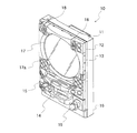
以下、本発明の実施の形態における遊技機について図面を参照しながら説明する。なお、本発明の実施の形態では、遊技機としてパチンコ遊技機を例に説明している。図1は、本発明の実施の形態におけるパチンコ遊技機を表面側からみた斜視図であり、図2は、同パチンコ遊技機を背面側からみた斜視図である。 Hereinafter, a gaming machine according to an embodiment of the present invention will be described with reference to the drawings. In the embodiment of the present invention, a pachinko gaming machine is described as an example of the gaming machine. FIG. 1 is a perspective view of a pachinko gaming machine according to an embodiment of the present invention as seen from the front side, and FIG. 2 is a perspective view of the pachinko gaming machine as seen from the back side.
本発明の実施の形態におけるパチンコ遊技機10は、図1に示すように、外枠11、前枠12、窓枠13及び当該窓枠13に覆われた遊技盤30(後述)などを備えている。また、パチンコ遊技機10の背面には、図2に示すように、液晶ディスプレイ型の演出表示装置37(後述)などの表示制御や、可動役物及びLEDなどによる遊技演出の制御を行う表示演出サブ基板21、各種遊技音の出力制御を行う音サブ基板22、入賞時におけるパチンコ遊技機10の動作等を含むパチンコ遊技機10の主要な動作を制御する主基板23、パチンコ球(遊技球)の払い出し動作を制御する払出基板24、各基板等に電源を供給する電源基板25等の各種基板が例えば透明ケースに収納された状態で取り付けられている。
As shown in FIG. 1, the
具体的に、外枠11は、パチンコホールの台島に設置されており、図1に示すように、前後面が開口するように四角筒状に形成されている。前枠12は、外枠11の前端面に左側辺部の垂直な軸を中心に回動可能に装着されている。また、この前枠12の前面下部には、上面が開口する下皿14と、上面が開口する上皿15とが固定されている。
Specifically, the
下皿14の右端周辺にはハンドル台16が固定されており、ハンドル台16には発射ハンドル19が回動自在に装着されている。この発射ハンドル19の後方には発射モータが固定されており、発射モータの回転軸には打球槌が連結されている。この発射モータは打球槌の駆動源に相当するものであり、発射ハンドル19が回動操作されたときには発射モータに駆動電源が供給される。その結果、打球槌が駆動して上皿15内のパチンコ球が弾き出される。
A
窓枠13は前枠12の前面に装着されている。この窓枠13には円形孔状の窓部17が形成されており、窓部17の内周面には透明なガラスやアクリル等からなる透明板17aが固定されている。この窓枠13の左上隅部及び右上隅部の裏面には、遊技音を出力するスピーカ18が固定されている。また、窓枠13には複数の装飾LEDが固定されている。
The
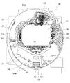
上述の遊技盤30は、前枠12の後面に装着されている。以下、この遊技盤30及び遊技盤30に備えられる各構成部材について図3を参照して詳細に説明する。図3は、本発明の実施の形態における遊技盤30の正面図である。この遊技盤30は、上述のように前枠12の後面に装着されており、窓枠13の透明板17aに前方から覆われている。
The above-described
遊技板31は、遊技盤30の有する各構成部材を固定するための板である。ガイドレール32は、この遊技板31の表面側に固定されて、この遊技板31上に、パチンコ球の発射通路31aと遊技領域31bとを形成する。遊技領域31bには複数の障害釘(図示省略)が打ち込まれている。上述の打球槌が弾いたパチンコ球は、発射通路31aを通して遊技領域31b内に放出される。そして、遊技領域31b内に放出されたパチンコ球は障害釘に当りながら転動して遊技領域31b内を落下する。
The
遊技盤30のほぼ中央部には、センター役物と呼ばれる装飾演出手段が設けられている。本実施の形態におけるセンター役物は、カラー液晶ディスプレイ等を用いた演出表示装置37と、その周りに配置された装飾部材等で構成されている。このうち、演出表示装置37は、大当り遊技状態を発生させるか否かの判定結果に基づき変動演出表示を行う広い面積の表示画面37aを有している。
Nearly the center of the
また、演出表示装置37の上方には、可動体が電気的に可動する第1可動役物100が配置されている。また、演出表示装置37の左側方には、可動体が電気的に可動する、本発明の可動役物としての第2可動役物200が配置されている。
In addition, a first
第1可動役物100は、演出表示装置37の表示画面37aで行われる変動演出表示などのパチンコ遊技機10の演出制御に応じて可動することで遊技の演出を行うようになっている。本実施の形態の第1可動役物100は、龍の頭及び胴体を模した複数の可動体を有している。そして、この第1可動役物100は、図示しない駆動源としてのアクチュエータ(ソレノイド、モータ等からなり、本実施の形態ではモータ)に電気的に駆動されて、龍の頭部及び上顎を模した第1可動体(図示省略)、龍の下顎を模した第2可動体(図示省略)、龍の胴体を模した第3可動体(図示省略)が、少なくとも往復駆動(本実施の形態ではパチンコ遊技機10の上下方向への往復駆動)又は回動駆動するように構成されている。
The first
第2可動役物200は、第1可動役物100と同様に、演出表示装置37の表示画面37aで行われる変動演出表示などのパチンコ遊技機10の演出制御に応じて可動することで遊技の演出を行うようになっている。本実施の形態の第2可動役物は、龍の尻尾を模した可動体を有している。そして、この第2可動役物200は、本発明の駆動源としてのアクチュエータ201(ソレノイド、モータ等からなり、本実施の形態ではモータ)に電気的に駆動されて、龍の尻尾を模した可動体202が、スライド駆動又は回動駆動するように構成されている。なお、本実施の形態ではパチンコ遊技機10の上下方向(本実施の形態では、重力方向及び反重力方向と同じ方向)Fを軸方向として回動駆動するようになっている。また、第2可動役物200の詳細については後述する。
Similar to the first
また、演出表示装置37の右側方には、第1固定演出部材38が配置されている。本実施の形態の第1固定演出部材38は、龍の胴体を模した形状に形成されている。このように、本実施の形態では、龍の頭及び胴体を模した第1可動役物100、龍の胴体を模した第1固定演出部材38、龍の尻尾を模した第2可動役物200を、演出表示装置37の周囲に配置することにより、これらの可動役物及び固定演出部材で演出表示装置37の周囲を1匹の龍が囲んでいるような状態を表現している。
A first
また、第1固定演出部材38のさらに右側方には、第2固定演出部材39が配置されている。また、演出表示装置37の下方には、パチンコ球を始動入賞口33に入賞し易くなるように誘導する誘導路を始動入賞口33の真上に設けた、略水平面で構成されたステージ36が配置されている。このステージ36には、遊技領域31bの途中から第2可動役物200の左側に設けられたワープ通路(図示省略)に入ったパチンコ球が誘導されるように構成されている。
Further, a second
また、遊技領域31b内において、演出表示装置37の下方には始動入賞口33が配置されている。この始動入賞口33は、パチンコ球が入賞することによって、遊技者に有利な大当り遊技状態を発生させるか否かの判定を行う起点となるものであり、上方に開口するポケット状に形成されており、開閉可能な一対の可動片33xを備えている。始動入賞口33は、可動片33xが閉塞されているときには開口面積が小さくなってパチンコ球が入賞し難くなり、可動片33xが開放されているときには開口面積が大きくなってパチンコ球が入賞し易くなる。
In addition, a
また、始動入賞口33の下方には、大入賞口34が配置されている。この大入賞口34は図示しないアクチュエータの作動により開閉する開閉扉34aを備えており、この開閉扉34aは、遊技状態が大当り遊技状態になると開口し、その際には大入賞口34が上方に向かってポケット状に幅広く開口し、多数のパチンコ球が同時かつ連続的に大入賞口34に入賞可能となる。
In addition, a large winning
また、遊技領域31b内の所定位置には、パチンコ球が入賞可能な一般入賞口35が上方に開口するポケット状に形成されている(本実施の形態では、遊技領域31bの左下部に複数の一般入賞口35が形成されている)。
Further, at a predetermined position in the
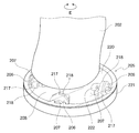
次に、第2可動役物200について、図4〜図8を参照して、さらに詳細に説明する。図4は、本発明の実施の形態における第2可動役物の正面簡略図であり、図5は、図4のA−A線での断面を示す横断面図であり、図6は、図4のB−B線での断面を示す横断面図であり、図7は、図6のC−C線での断面を示す横断面図であり、図8は、図4の第2可動役物の一部斜視図である。なお、図4〜図8については、便宜上、実際の構成を簡略化したり省略したりして図示している場合がある。
Next, the second
第2可動役物200は、図4に示すように、表示演出サブ基板21からの指示を受け、かつ、電源基板25からの電源供給を受けて電気的に駆動力を発生させる本発明の駆動源としてのアクチュエータ201(本実施の形態ではモータ)と、アクチュエータ201の駆動力により、上下方向F以外の駆動方向(本実施の形態では右回り又は左回りの回転方向E)に駆動される、龍の尻尾を模した可動体202と、可動体202に設けられた本発明の連結部としての連結孔203の上方に配置されて当該連結孔203に連結され、駆動源201の駆動力を可動体202に伝達する駆動力伝達手段204と、可動体202の底部及び可動体202の下方において可動体202の底部が接地する接地部に設けられ、可動体202を駆動(本実施の形態では回動)可能な状態に支持する(本実施の形態では下方から支持する)可動体支持手段205とを有している。
As shown in FIG. 4, the second
駆動力伝達手段204は、アクチュエータ201の回動軸206に固定された第1平歯車207と歯合する第2平歯車209、当該第2平歯車209の中心に固定された横軸208上の所定位置に固定された第1かさ歯車210、当該第1かさ歯車210と歯合する第2かさ歯車212、当該第2かさ歯車212の中心に固定された縦軸211、当該縦軸211を上方から挿通して回動自在に保持する挿通孔213を有し遊技盤30側に固定されたブッシュ214等を有している。なお、図示しないが、駆動力伝達手段204には、センター役物側に固定されてアクチュエータ201や横軸208等を可動体202とは別に支持する種々の支持部材を有している。
The driving force transmission means 204 is a
第2かさ歯車212に固定された本実施の形態の縦軸211は、図5に示すように、切欠部215を備えた断面視略D字状に形成されている。また、ブッシュ214の挿通孔213を貫通させた縦軸211を上方から挿通する可動体202の連結孔203は、平面部216を備えた断面視略D字状に形成されており、縦軸211より若干大きく形成されている。これらのことから、連結孔203に縦軸211を挿通された状態では、まず、連結孔203が縦軸211より大きく形成されていることで、挿通方向である上下方向Fに対しては連結孔203と縦軸211が連結(係合)されずに連結孔203の中で縦軸211が上下動自在とされている。その上で、連結孔203と縦軸211の形状が断面視略D字状のような挿通した状態で互いに回動自在とはならない形状とされていることで、駆動方向である回動方向Eに対しては第2かさ歯車212の回動に応じて縦軸211が回動方向Eに回動したときに、所定角度回動したところで互いに断面視略D字状に形成された縦軸211が連結孔203の壁面に引っ掛かり、連結孔203と縦軸211が連結(係合)されるようになっている。
As shown in FIG. 5, the
この結果、本発明の連結部としての連結孔203における駆動力伝達手段204と可動体202との連結状態が、縦軸211の挿通方向である上下方向Fに対しては連結されずに上下動自在となり、可動体202の駆動方向である回転方向Eに対しては連結されて駆動力伝達手段204の縦軸211の回動に応じて可動体202が回動し、駆動力伝達手段204が可動体202とは別に支持されている、という状態になる。このような上下方向Fの動きが固定されない連結状態により、駆動力伝達手段204には可動体202の重量が掛からず、かつ、回動方向Eの動きは伝達されることから、駆動源201の駆動力は可動体202に伝達される、という構成が成立している。
As a result, the connection state of the driving force transmission means 204 and the
なお、連結孔203と縦軸211における略D字状の断面形状は、互いに相似形でも異なる形であっても良く、また、略D字状以外の形(例えば、三角形等の多角形)であっても良い。また、連結孔203と縦軸211の断面形状は、上下方向のどの箇所でも同じ形状である必要はない。例えば、縦軸211が断面視略円形状でその上下方向Fの一部箇所に突起が設けられており、連結孔203をこれが上方から挿通可能な形状とすることで、上下方向Fの動きは固定されず、かつ、回動方向Eの動きは伝達可能とするようになっていても良い。要は、本発明の連結部としての連結孔203と本発明の駆動力伝達手段204の一部である縦軸211の互いの形状が、上下方向Fの動きは固定されずに、駆動方向である回動方向Eの動きは伝達可能となる形状になっていれば良い。
Note that the substantially D-shaped cross-sectional shape of the connecting
また、可動体支持手段205は、図6〜図8に示すように、可動体202の底部に可動体202の一部として設けられた部材と、可動体202の底部が接地する接地部に可動体202とは別部材として設けられた部材とで構成されている。詳しくは、図8に示すように、可動体支持手段205は、可動体202の底部に可動体202の一部として固定された底面板220と、当該底面板220と一体に接合された車輪状回動体用枠部材221とを有し、車輪状回動体用枠部材221には、複数の車輪状回動体206を回動可能に支持する複数の支持部222が形成されている。そして、当該支持部222には、複数の車輪状回動体206が取り付けられている。また、可動体202と別部材として、可動体202の下方において可動体202の底部が接地する接地部に、複数の車輪状回動体206が接面して回動するレール部208を有している。
Further, as shown in FIGS. 6 to 8, the movable body supporting means 205 is movable to a member provided as a part of the
なお、前記した車輪状回動体206等とレール部208は上下が逆に設けられていても良く、その場合は、レール部208が可動体202の底部に可動体202の一部として設けられ、車輪状回動体206が可動体202の下方に可動体202とは別部材として設けられることになる。
In addition, the above-described wheel-shaped
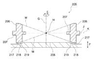
前記した複数の車輪状回動体206は、その車軸207がそれぞれ、回動する可動体202の上下方向Fに延びる回動中心線G上の一点である中心点Hを含んだ回動中心線Gに対する垂直面J上に位置している。また、複数の車輪状回動体206は、回動中心線G上の中心点Hから等距離となる位置、すなわち中心点Hを中心とした同心円の上に配置されている。また、複数の車輪状回動体206は、車軸207の延長線Kが、中心点Hで交わるように構成されている。
Each of the plurality of wheel-like
また、車輪状回動体206には、レール部208に接面する接面部(車輪状回動体206の周面(側面))217を有しており、この接面部217の少なくとも一部には傾斜面218が形成されており、当該傾斜面218は、その面を延長した先が中心点Hで交わるようになっている。言い換えると、傾斜面218は、接面部217における車軸方向の途中の一点から中心点Hに延びる直線Mと平行となるように形成されている。本実施の形態では、車輪状回動体206の接面部217における中心点H寄りの約3/5程度の幅の面が傾斜して傾斜面218となっている。また、本実施の形態では、傾斜面218を除く接面部217は回動中心線Gに垂直な面、すなわち水平面となっている。なお、可動体202のスムーズな可動のためには、接面部217の全てが傾斜面218となっているのが理論上良いが、実際上は、接面部217の全てを傾斜面218とすると、接面部217の最も外側が鋭角状態となって、摩耗し易い状態となるため、接面部217の外側部分を傾斜のない平坦部とするのが好ましい。
Further, the wheel-like
また、複数の車輪状回動体206が接面して回動するレール部208は、円形状に形成されており、車輪状回動体206が常にこのレール部208に接面して回動するようになっている。また、レール部208において、車輪状回動体206の傾斜面218が接面する位置には、傾斜面218と平行となる傾斜レール部219が形成されている。本実施の形態の傾斜レール部219は、本実施の形態における傾斜面218と平行になるべく、回動中心線Gを中心とした円の内側から外側に向かって上方から下方に傾斜するようになっており、レール部208全体としては略円錐台形状に形成されている。
Further, the
このような構成により、アクチュエータ201の駆動力により可動体202が回動する際に、可動体202の底部に固定された底面板220と一体にされた車輪状回動体用枠部材221の支持部222に取り付けられた可動体支持手段205の車輪状回動体206が、可動体202の回動駆動に応じて回動中心線Gを中心として、その下方に設けられたレール部208上を回動するが、このとき、車輪状回動体206及びレール部208の一部分に無理な力が掛からないように、傾斜面218及び傾斜レール部219を有しており、このことで、スムーズな可動体202の可動を実現することができるようになっている。
With such a configuration, when the
以上のように、本実施の形態のパチンコ遊技機10によれば、アクチュエータ201の駆動力は駆動力伝達手段204を介して可動体202に伝達するが、アクチュエータ201や駆動力伝達手段204に対して可動体202の重量は掛からないように構成されているため、アクチュエータ201自体やアクチュエータ201と可動体202とを連結する駆動力伝達手段204に無理な力が掛からず、その結果、第2可動役物200における可動体202の駆動状態を良好に保つことができる。
As described above, according to the
さらに、駆動力伝達手段204と可動体202とは、上下方向Fに対しては連結されずに駆動方向である回動方向Eには連結された状態に構成されているため、可動体202の駆動で当該可動体202を支持する(本実施の形態では下方から支持する)可動体支持手段205が、摩耗等により上下方向Fにおける位置ずれを起こし、これに伴い可動体202の上下方向Fの位置にずれが生じても、可動体202の回動方向Eへの駆動には影響を与えず、可動体202を回動方向Eに確実に駆動させることができる。
Further, since the driving force transmission means 204 and the
特に、本実施の形態のように、駆動源からの駆動力をかさ歯車を用いて可動体に伝達する構成の場合、かさ歯車は歯合するときの歯車同士の位置関係等に厳しい精度が求められる。このため、歯車や軸の摩耗によって、かさ歯車の位置関係等に変化が起こると、すぐに正常な歯合状態を保つことができなくなってしまい、その結果、駆動源からの駆動力を可動体に正常に伝達できなくなってしまう虞がある。しかし、本発明のように、かさ歯車に対して可動体の重量を掛けないようになっていると、かさ歯車の摩耗や位置精度の変化を極力抑えることができ、なおかつ、可動体や可動体支持手段の摩耗により可動体の上下方向の位置に変化が生じても、その変化が直接、駆動力伝達手段のかさ歯車の歯合状態に影響を与えないようにすることができるため、可動役物を長い期間、正常な動作で使用することができるものである。 In particular, in the case of a configuration in which the driving force from the driving source is transmitted to the movable body using the bevel gear as in the present embodiment, the bevel gear requires strict accuracy in the positional relationship between the gears when meshing. It is done. For this reason, if a change occurs in the positional relationship of the bevel gear due to wear of the gear and the shaft, the normal engagement state cannot be maintained immediately, and as a result, the driving force from the driving source is transferred to the movable body. May not be able to be transmitted normally. However, if the weight of the movable body is not applied to the bevel gear as in the present invention, the wear of the bevel gear and the change in position accuracy can be suppressed as much as possible, and the movable body and the movable body Even if the vertical position of the movable body changes due to wear of the support means, it is possible to prevent the change from directly affecting the meshing state of the bevel gear of the driving force transmission means. An object can be used in a normal operation for a long period of time.
また、本実施の形態のパチンコ遊技機10によれば、第2可動役物200における可動体202の車輪状回動体206に無理な力が掛からないため、可動体202をスムーズに回動させることができ、かつ、第2可動役物200を破損させないようにすることができる。
In addition, according to the
なお、以上説明した各実施の形態は、本発明の理解を容易にするために記載されたものであって、本発明を限定するために記載されたものではない。 Each embodiment described above is described in order to facilitate understanding of the present invention, and is not described in order to limit the present invention.
例えば、前記した実施の形態では、遊技機としてパチンコ遊技機を挙げて説明したが、本発明はこれに限るものではなく、パチスロ遊技機等の他の遊技機にも適用可能である。 For example, in the above-described embodiment, a pachinko gaming machine has been described as a gaming machine, but the present invention is not limited to this and can be applied to other gaming machines such as a pachislot gaming machine.
また、前記した実施の形態では、駆動力伝達手段の一部にかさ歯車を用いた構成となっていたが、これに限るものではなく、本発明の駆動力伝達手段は、例えば平歯車のみを用いた歯車機構等、種々の構成から成っていても良い。 In the embodiment described above, the bevel gear is used as a part of the driving force transmission means. However, the invention is not limited to this, and the driving force transmission means of the present invention includes, for example, only a spur gear. You may consist of various structures, such as the used gear mechanism.
また、可動体支持手段の構成としては、前記した実施の形態に限るものではなく、例えば、可動体とセンター役物との両方にレール部を備え、可動体のレール部とセンター役物のレール部との間に車輪状回動体を備えた構成となっていても良い。 Further, the configuration of the movable body support means is not limited to the above-described embodiment. For example, both the movable body and the center accessory are provided with rail portions, and the rail portion of the movable body and the rail of the center accessory are provided. It may be the structure provided with the wheel-shaped rotating body between the parts.
また、車輪状回動体の形状等は、前記した実施の形態のものに限らず、同様の構成が得られるものであれば、適宜の形状のものを使用しても良い。 Further, the shape and the like of the wheel-like rotating body are not limited to those of the above-described embodiments, and those having an appropriate shape may be used as long as the same configuration can be obtained.
10…パチンコ遊技機(遊技機)、30…遊技盤、31b…遊技領域、200…第2可動役物(可動役物)、201…アクチュエータ(駆動源)、202…可動体、203…連結孔(連結部)、204…駆動力伝達手段、205…可動体支持手段、206…車輪状回動体、207…車軸、208…レール部、217…接面部、218…傾斜面、219…傾斜レール部
DESCRIPTION OF
Claims (1)
前記可動役物は、
電気的に駆動力を発生させる駆動源と、
前記駆動源の駆動力により回動する可動体と、
前記可動体の底部及び前記可動体の底部が接地する接地部に設けられ、前記可動体を回動可能な状態に支持する可動体支持手段と、
を有し、
前記可動体支持手段は、
車軸が前記可動体の回動中心線上の一点を含んだ前記回動中心線に対する垂直面上に位置すると共に、前記一点から等距離となる位置に配置され、かつ、前記車軸の延長線が、前記一点で交わるように構成された複数の車輪状回動体を前記可動体の底部に有し、前記複数の車輪状回動体が接面して回動する円形状のレール部を前記接地部に有する構成、
又は、
前記複数の車輪状回動体を前記接地部に有し、前記レール部を前記可動体の底部に有する構成、
のいずれかの構成を有しており、
前記車輪状回動体には、前記レール部に接面する接面部の少なくとも一部に傾斜面が形成されており、当該傾斜面は、その面を延長した先が前記一点で交わるようになっており、
前記レール部には、前記傾斜面が接面する位置に、当該傾斜面と平行となる傾斜レール部が形成されていることを特徴とする遊技機。 In a gaming machine having a movable accessory in a gaming area formed on the surface side of the gaming board,
The movable accessory is
A driving source that electrically generates a driving force;
A movable body that rotates by a driving force of the driving source;
A movable body supporting means that is provided in a ground portion where the bottom of the movable body and the bottom of the movable body are grounded, and supports the movable body in a rotatable state;
Have
The movable body support means includes
The axle is located on a vertical plane with respect to the pivot center line including one point on the pivot center line of the movable body, and is disposed at a position equidistant from the one point, and an extension line of the axle is A plurality of wheel-shaped rotating bodies configured to intersect at the one point are provided at the bottom of the movable body, and a circular rail portion that rotates with the plurality of wheel-shaped rotating bodies in contact with each other is formed on the grounding section. Having a configuration,
Or
A structure having the plurality of wheel-like rotating bodies in the grounding portion and the rail portion in a bottom portion of the movable body;
Have one of the following configurations:
In the wheel-like rotating body, an inclined surface is formed on at least a part of a contact surface portion that contacts the rail portion, and the inclined surface is formed such that the tip of the surface extends at the one point. And
A gaming machine, wherein the rail portion is formed with an inclined rail portion parallel to the inclined surface at a position where the inclined surface contacts.
Priority Applications (1)
| Application Number | Priority Date | Filing Date | Title |
|---|---|---|---|
| JP2009131512A JP5099080B2 (en) | 2009-05-29 | 2009-05-29 | Game machine |
Applications Claiming Priority (1)
| Application Number | Priority Date | Filing Date | Title |
|---|---|---|---|
| JP2009131512A JP5099080B2 (en) | 2009-05-29 | 2009-05-29 | Game machine |
Publications (2)
| Publication Number | Publication Date |
|---|---|
| JP2010273996A JP2010273996A (en) | 2010-12-09 |
| JP5099080B2 true JP5099080B2 (en) | 2012-12-12 |
Family
ID=43421491
Family Applications (1)
| Application Number | Title | Priority Date | Filing Date |
|---|---|---|---|
| JP2009131512A Expired - Fee Related JP5099080B2 (en) | 2009-05-29 | 2009-05-29 | Game machine |
Country Status (1)
| Country | Link |
|---|---|
| JP (1) | JP5099080B2 (en) |
Family Cites Families (4)
| Publication number | Priority date | Publication date | Assignee | Title |
|---|---|---|---|---|
| JPS5784081A (en) * | 1980-11-13 | 1982-05-26 | Tomy Kogyo Co | Rail travelling toy |
| JPH04182207A (en) * | 1990-11-16 | 1992-06-29 | Daifuku Co Ltd | Horizontally rotational shelf device |
| JP5070454B2 (en) * | 2006-04-24 | 2012-11-14 | 株式会社大一商会 | Game machine |
| JP5096021B2 (en) * | 2007-03-13 | 2012-12-12 | 日本ぱちんこ部品株式会社 | Rendering device for gaming machine and gaming machine using the same |
-
2009
- 2009-05-29 JP JP2009131512A patent/JP5099080B2/en not_active Expired - Fee Related
Also Published As
| Publication number | Publication date |
|---|---|
| JP2010273996A (en) | 2010-12-09 |
Similar Documents
| Publication | Publication Date | Title |
|---|---|---|
| JP2017070383A (en) | Game machine | |
| JP5722143B2 (en) | Game machine | |
| JP2010273994A (en) | Pachinko game machine | |
| JP2008284227A (en) | Game machine | |
| JP4654254B2 (en) | Decorative body unit, game board, and pachinko machine | |
| JP5477324B2 (en) | Movable accessory device for gaming machines | |
| JP5484778B2 (en) | Pachinko machine | |
| JP5617816B2 (en) | Game machine | |
| JP5477334B2 (en) | Game machine directing device | |
| JP5537384B2 (en) | Bullet ball machine | |
| JP2014230598A (en) | Game machine | |
| JP5099080B2 (en) | Game machine | |
| JP5741267B2 (en) | Movable direction device for gaming machine | |
| JP5110041B2 (en) | Game machine | |
| JP2010213874A (en) | Game machine | |
| JP4342925B2 (en) | Game machine | |
| JP2009195389A (en) | Decorative body unit, game board and pachinko game machine | |
| JP6095448B2 (en) | Game machine | |
| JP5981895B2 (en) | Game machine | |
| JP5126164B2 (en) | Pachinko machine | |
| JP6235975B2 (en) | Game machine | |
| JP6116322B2 (en) | Game machine | |
| JP4726921B2 (en) | Decorative unit, game board, and pachinko machine | |
| JP2013017765A (en) | Game machine | |
| JP5240710B2 (en) | Game board unit |
Legal Events
| Date | Code | Title | Description |
|---|---|---|---|
| A621 | Written request for application examination |
Free format text: JAPANESE INTERMEDIATE CODE: A621 Effective date: 20101126 |
|
| TRDD | Decision of grant or rejection written | ||
| A977 | Report on retrieval |
Free format text: JAPANESE INTERMEDIATE CODE: A971007 Effective date: 20120822 |
|
| A01 | Written decision to grant a patent or to grant a registration (utility model) |
Free format text: JAPANESE INTERMEDIATE CODE: A01 Effective date: 20120828 |
|
| A01 | Written decision to grant a patent or to grant a registration (utility model) |
Free format text: JAPANESE INTERMEDIATE CODE: A01 |
|
| A61 | First payment of annual fees (during grant procedure) |
Free format text: JAPANESE INTERMEDIATE CODE: A61 Effective date: 20120910 |
|
| FPAY | Renewal fee payment (event date is renewal date of database) |
Free format text: PAYMENT UNTIL: 20151005 Year of fee payment: 3 |
|
| R150 | Certificate of patent or registration of utility model |
Free format text: JAPANESE INTERMEDIATE CODE: R150 |
|
| FPAY | Renewal fee payment (event date is renewal date of database) |
Free format text: PAYMENT UNTIL: 20151005 Year of fee payment: 3 |
|
| R255 | Notification of exclusion from application |
Free format text: JAPANESE INTERMEDIATE CODE: R2525 |
|
| LAPS | Cancellation because of no payment of annual fees |


