JP5098103B2 - Headlight support structure for saddle-ride type vehicles - Google Patents
Headlight support structure for saddle-ride type vehicles Download PDFInfo
- Publication number
- JP5098103B2 JP5098103B2 JP2008071657A JP2008071657A JP5098103B2 JP 5098103 B2 JP5098103 B2 JP 5098103B2 JP 2008071657 A JP2008071657 A JP 2008071657A JP 2008071657 A JP2008071657 A JP 2008071657A JP 5098103 B2 JP5098103 B2 JP 5098103B2
- Authority
- JP
- Japan
- Prior art keywords
- support member
- bar handle
- headlight
- attached
- saddle
- Prior art date
- Legal status (The legal status is an assumption and is not a legal conclusion. Google has not performed a legal analysis and makes no representation as to the accuracy of the status listed.)
- Expired - Fee Related
Links
Images

Classifications
-
- B—PERFORMING OPERATIONS; TRANSPORTING
- B62—LAND VEHICLES FOR TRAVELLING OTHERWISE THAN ON RAILS
- B62J—CYCLE SADDLES OR SEATS; AUXILIARY DEVICES OR ACCESSORIES SPECIALLY ADAPTED TO CYCLES AND NOT OTHERWISE PROVIDED FOR, e.g. ARTICLE CARRIERS OR CYCLE PROTECTORS
- B62J6/00—Arrangement of optical signalling or lighting devices on cycles; Mounting or supporting thereof; Circuits therefor
- B62J6/02—Headlights
- B62J6/022—Headlights specially adapted for motorcycles or the like
- B62J6/027—Supporting means therefor, e.g. mounting brackets
-
- B—PERFORMING OPERATIONS; TRANSPORTING
- B62—LAND VEHICLES FOR TRAVELLING OTHERWISE THAN ON RAILS
- B62J—CYCLE SADDLES OR SEATS; AUXILIARY DEVICES OR ACCESSORIES SPECIALLY ADAPTED TO CYCLES AND NOT OTHERWISE PROVIDED FOR, e.g. ARTICLE CARRIERS OR CYCLE PROTECTORS
- B62J6/00—Arrangement of optical signalling or lighting devices on cycles; Mounting or supporting thereof; Circuits therefor
- B62J6/02—Headlights
- B62J6/022—Headlights specially adapted for motorcycles or the like
- B62J6/026—Headlights specially adapted for motorcycles or the like characterised by the structure, e.g. casings
Landscapes
- Engineering & Computer Science (AREA)
- Mechanical Engineering (AREA)
- Motorcycle And Bicycle Frame (AREA)
- Lighting Device Outwards From Vehicle And Optical Signal (AREA)
Description
本発明は、バーハンドルにヘッドライト及びヘッドライトカバーを取り付けるための鞍乗り型車両のヘッドライト支持構造に関する。 The present invention relates to a headlight support structure for a saddle-ride type vehicle for attaching a headlight and a headlight cover to a bar handle.
従来、不整地を走行可能なATV型車両(鞍乗り型車両)では、車両前方を照らすヘッドライトをハンドル部分に取り付けたものがある。このハンドル部分には、ステアリングシャフトにブラケット等が取り付けられており、ヘッドライトは、このブラケットを介して取り付けられている(例えば、特許文献1参照)。
また、バーハンドルとフロントフォークとの角度を調整するために、バーハンドルに取り付けられたハンドルカバーとステアリングシャフトとの間に隙間を設ける技術も知られている(例えば、特許文献2参照)。
In addition, a technique for providing a gap between a handle cover attached to the bar handle and the steering shaft in order to adjust the angle between the bar handle and the front fork is also known (see, for example, Patent Document 2).
このハンドル部分には、ヘッドライトの他に、速度等を表示するメーター類が取り付けられる。また、これらメーター類の配線やアクセルレバーに接続されたスロットルケーブルなどが配線されることになる。そのため、これら部品を簡単にかつ容易に取り付けられる構造が望まれる。 In addition to the headlight, meters for displaying speed and the like are attached to the handle portion. In addition, wiring of these meters and a throttle cable connected to an accelerator lever are wired. Therefore, a structure in which these parts can be easily and easily attached is desired.
本発明は、上述した事情を鑑みてなされたものであり、ヘッドライトをバーハンドルに容易に取り付けることができる鞍乗り型車両のヘッドライト支持構造を提供することにある。 The present invention has been made in view of the above-described circumstances, and it is an object of the present invention to provide a headlight support structure for a saddle-ride type vehicle in which a headlight can be easily attached to a bar handle.
本願発明では、前輪を操向するバーハンドルにヘッドライトを支持させる支持部材と、前記ヘッドライトを覆うように前記支持部材に支持されるヘッドライトカバーとを備えた鞍乗り型車両において、前記支持部材は、前記バーハンドルに設けられたブラケットに固定される固定部と、前記バーハンドルを上方から覆う第1保持部と、前記バーハンドルを前方から覆う第2保持部とを有し、前記固定部によりバーハンドルのブラケットに固定されると共に、第1保持部及び第2保持部をバーハンドルに隙間をあけて保持させることでバーハンドルに支持され、前記支持部材の前部の左右から前方に延びる第1腕部と第2腕部とによってヘッドライトを支持させたことを特徴とする。
この構成によれば、支持部材は、ハンドルに固定部を固定するだけで取り付けられるようになる。
According to the present invention, in the saddle-ride type vehicle comprising: a support member that supports a headlight on a bar handle that steers a front wheel; and a headlight cover that is supported by the support member so as to cover the headlight. The member has a fixing portion fixed to a bracket provided on the bar handle, a first holding portion that covers the bar handle from above, and a second holding portion that covers the bar handle from the front, and the fixing Is fixed to the bracket of the bar handle by the portion, and is supported by the bar handle by holding the first holding portion and the second holding portion with a gap in the bar handle, and forward from the left and right of the front portion of the support member The headlight is supported by the extending first arm portion and second arm portion.
According to this configuration, the support member can be attached simply by fixing the fixing portion to the handle.
また、前記第1保持部の近傍で、支持部材とバーハンドルとの間に弾性部材を介在させることもできる。
この構成によれば、支持部材とバーハンドルとを弾性支持させることができる。
Further, an elastic member may be interposed between the support member and the bar handle in the vicinity of the first holding portion.
According to this configuration, the support member and the bar handle can be elastically supported.
さらに、前記支持部材を樹脂材料で一体に形成し、前記支持部材にメーター類支持部およびヘッドライトやメーター類の配線経路を形成することもできる。
この構成によれば、ハンドル部分に取り付けるメーター類支持部やそれに付属する配線等の各装備を1つの支持部材で取り付けることができる。
Furthermore, the support member can be integrally formed of a resin material, and a meter support portion and a wiring path for a headlight or a meter can be formed on the support member.
According to this configuration, each equipment such as a meter support portion attached to the handle portion and wiring attached thereto can be attached by one support member.
本発明に係る鞍乗り型車両のヘッドライト支持構造では、前記支持部材は、前記バーハンドルに設けられたブラケットに固定される固定部と、前記バーハンドルを上方から覆う第1保持部と、前記バーハンドルを前方から覆う第2保持部とを有し、前記固定部によりバーハンドルのブラケットに固定されると共に、第1保持部及び第2保持部をバーハンドルに保持させることでバーハンドルに支持され、前記支持部材の前部の左右から前方に延びる第1腕部と第2腕部とによってヘッドライトを支持させているので、支持部材は、ハンドルに固定部を固定するだけで取り付けられるようになる。また、第1保持部及び第2保持部は、バーハンドルの上方および前方から位置を合わせ、バーハンドルと隙間をあけて保持しているので、第1保持部及び第2保持部をボルト等で固定しないため、支持部材を容易に取り付けることができる。また、支持部材に車体上方または前方からの荷重が作用したとしても、支持部材が撓み、第1保持部及び第2保持部がバーハンドルと接触して荷重を受けることができる。その結果、ヘッドライトの取付に必要な強度を確保することができる。 In the headlight support structure for a saddle-ride type vehicle according to the present invention, the support member includes a fixing part fixed to a bracket provided on the bar handle, a first holding part that covers the bar handle from above, A second holding portion that covers the bar handle from the front, and is fixed to the bracket of the bar handle by the fixing portion, and supported by the bar handle by holding the first holding portion and the second holding portion on the bar handle. Since the headlight is supported by the first arm portion and the second arm portion that extend forward from the left and right of the front portion of the support member, the support member can be attached simply by fixing the fixing portion to the handle. become. In addition, since the first holding part and the second holding part are positioned from above and in front of the bar handle and are held with a gap from the bar handle, the first holding part and the second holding part are secured with bolts or the like. Since it is not fixed, the support member can be easily attached. Even if a load from above or on the front of the vehicle body acts on the support member, the support member bends, and the first holding part and the second holding part can contact the bar handle and receive the load. As a result, the strength required for mounting the headlight can be ensured.
また、前記第1保持部の近傍で、支持部材とバーハンドルとの間に弾性部材を介在させているので、支持部材とバーハンドルとを弾性支持させることができ、車体の振動等が支持部材に伝わらないようにすることができる。その結果、ヘッドライトに作用する負荷を軽減させることができる。 In addition, since the elastic member is interposed between the support member and the bar handle in the vicinity of the first holding portion, the support member and the bar handle can be elastically supported, and the vibration of the vehicle body or the like is supported by the support member. It can be prevented from being transmitted to. As a result, the load acting on the headlight can be reduced.
さらに、前記支持部材を樹脂材料で一体に形成し、前記支持部材にメーター類支持部およびヘッドライトやメーター類の配線経路を形成しているので、ハンドル部分に取り付ける各装備を1つの支持部材で取り付けることができ、各装置を取り付けるために個々に支持部材を設ける場合と比較して、各装備の取り付け作業を容易に行うことができる。また、配線をコンパクトにまとめることができ、外観性を向上させることができる。 Further, since the support member is integrally formed of a resin material, and the meter support portion and the headlight and meter wiring paths are formed on the support member, each equipment to be attached to the handle portion is formed with one support member. Compared with the case where a support member is individually provided for attaching each device, the attachment work of each equipment can be easily performed. Further, the wiring can be made compact and the appearance can be improved.
本発明を実施するための最良の形態を添付図に基づいて以下に説明する。なお、明細書中で使用される前後、左右、上下等の向きは、運転者から見た方向をいうものとする。また、図面は符号の向きに見るものとする。 The best mode for carrying out the present invention will be described below with reference to the accompanying drawings. In addition, directions such as front and rear, left and right, and up and down used in the specification refer to directions as viewed from the driver. The drawings are to be viewed in the direction of the reference numerals.
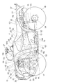
図1は本発明の鞍乗り型不整地走行車両の側面図である。
鞍乗り型不整地走行車両10(以下、単に「鞍乗り型車両10」という)は、車体フレーム11と、この車体フレーム11の中央下部に搭載したエンジン12と、このエンジン12に接続するとともに車体フレーム11に取り付けた動力伝達装置13と、左右の前輪17,17及び左右の後輪18,18を懸架する前サスペンション15及び後サスペンション16と、前輪17,17に連結するとともに車体フレーム11に取り付けたステアリング装置21とを備える四輪駆動車両である。
FIG. 1 is a side view of a saddle-ride type rough terrain vehicle of the present invention.
A saddle-ride type rough terrain vehicle 10 (hereinafter, simply referred to as a “saddle-
車体フレーム11は、メインフレーム25と、メインフレーム25の前後に取り付けた前フレーム26及び後フレーム27と、前フレーム26の下部の左右間に取り付けたブラケット31と、前フレーム26の上部の左右間に取り付けたクロスメンバ32とを有する。なお、33はメインフレーム25に取り付けた座席シート、34は燃料タンク、35は前フレーム26に取り付けたフロントガード、36は前フレーム26に取り付けたフロントキャリア、37はメインフレーム25の後部に取り付けたリアキャリアを示す。
The vehicle body frame 11 includes a main frame 25, a
前サスペンション15は、左右独立懸架で、車体フレーム11に上下揺動可能に取り付けた左右一対のフロントアッパアーム40,40及びフロントロアアーム41,41と、フロントアッパアーム40及びクロスメンバ32のそれぞれの間に取り付けた左右一対のフロントクッションユニット42,42とを備える。
後サスペンション16は、車体フレーム11に取り付けたリヤクッションユニット44を備える。
The
The
動力伝達装置13は、エンジン12の出力軸に連結した変速機47と、ギアチェンジペダル48と、変速機47の前後に連結した前駆動軸51及び後駆動軸52と、前駆動軸51に連結し且つ車体フレーム11側に取り付けた前最終減速装置53と、後駆動軸52に連結した後最終減速装置54とを有する。
The
ステアリング装置21は、メインフレーム25の前上部にシャフトホルダ55で取り付けたステアリングシャフト56と、ステアリングシャフト56に取り付けたバーハンドル57と、を有する。また、バーハンドル57の前方には、車両前方を照らすためのヘッドライト59が取り付けられている。このヘッドライト59は、ヘッドライトカバー58によって覆われている。
なお、61は前輪17,17の上方を覆うフロントフェンダ、62は後輪18,18の上方を覆うリヤフェンダである。
The
In addition, 61 is a front fender that covers the
エンジン12は、4サイクルエンジンであり、シリンダブロック63と、このシリンダブロック63の上部に取り付けたシリンダヘッド64と、このシリンダヘッド64の前部に接続した排気装置65と、シリンダヘッド64の後部に取り付けたスロットルボディ66とを備えている。シリンダヘッド64内には、動弁機構と、シリンダブロック63内に移動可能に挿入したピストンと、このピストンにコンロッドを介して連結したクランクシャフトとを備えている。
また、エンジン12の下側には、車体の下側のほぼ全体を覆うアンダーガード73が設けられている。
The engine 12 is a four-cycle engine, and includes a
An
ステアリングシャフト56の前方には、エンジン12を冷却するためのラジエータ75が設けられている。また、ステアリングシャフト56よりも前方に延び、ラジエータ75を支持するフレーム76には、ラジエータ75の後方でかつ上方にECU77(電子制御部品)が取り付けられている。また、車体後部には、バッテリー78が搭載されており、ECU77とバッテリー78は、後述するハーネスによって接続されている。これにより、ECU77に電源が供給されるようになっている。
A
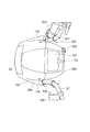
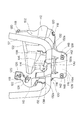
図2は、図1のバーハンドル部分を拡大して示す左側面図であり、図3は、図2の平面図である。また、図4は、ヘッドライトカバー58を取り外した状態を示す斜視図である。
バーハンドル57は、正面視で略U字形状を有しており、このU字形状に窪んだ部分100(以下、ハンドル部分100という)に支持部材102が取り付けられている。この支持部材102には、図4に示すように、ヘッドライト59と、車速等の情報を表示するメーター類60とが取り付けられている。
2 is an enlarged left side view of the bar handle portion of FIG. 1, and FIG. 3 is a plan view of FIG. FIG. 4 is a perspective view showing a state in which the
The
また、支持部材102には、これらのヘッドライト59及びメーター類60を覆うようにヘッドライトカバー58が取り付けられている。このヘッドライトカバー58は、前後に分割可能になっており、主にヘッドライト59を覆う前側カバー58aと、主にメーター類60とを覆う後側カバー58bとで構成されている。この前側カバー58aは、後側カバー58bを外さずに支持部材102から取り外すことができるようになっている。
Further, a
バーハンドル57の右側のグリップ部分には、アクセル操作をするためのスロットルレバー104が設けられている。また、バーハンドル57の左側のグリップ部分には、リアブレーキ106が設けられている。
また、メーター類60の右側部分には、図3に示すように、イグニッションスイッチ108が設けられている。さらに、メーター類60の下側の中央位置には、燃料タンク34とつながれたブリーザーホース109が引き回されている。
A
In addition, an
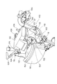
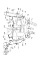
図5は、支持部材102をハンドル部分100に取り付けた状態を車体前方斜め左側から見た斜視図である。また、図6は、図5を車体後方斜め右側から見た斜視図である。
支持部材102は、樹脂材料で一体に成型されており、左側面を構成する第1腕部110と、右側面を構成する第2腕部112と、この第1腕部110及び第2腕部112の後端をつなぐ後壁部114と、この後壁部114の下側に位置する固定部116とを備えている。
FIG. 5 is a perspective view of the state in which the
The
左右の第1腕部110及び第2腕部112は、図5に示すように、左右対称に形成されている。この第1腕部110及び第2腕部112には、支持部材102の内側に向けて突出する突起部110a、112aがそれぞれ形成されており、この突起部110a、112aにヘッドライト59が着脱可能に支持されている(図4参照)。また、ヘッドライト59は、突起部110a、112aを中心に上下方向に回動可能であり、これによりエーミング調整ができるようになっている。
The left and right
第1腕部110及び第2腕部112の側面には、図5及び図6に示すように、上述した前側カバー58aをグロメット118で固定するための固定穴120がそれぞれに2箇所に形成されている。
また、第1腕部110及び第2腕部112の上面には、図6に示すように、支持部材102の内側に向かって突出するフランジ部122(メーター類支持部)がそれぞれ形成されている。このフランジ部122には、メーター類60が載置される。またフランジ部122には、メーター類60をグロメット126で固定するための固定穴124がそれぞれに2箇所に形成されている。
As shown in FIGS. 5 and 6, two fixing
Further, as shown in FIG. 6, flange portions 122 (meter support portions) that protrude toward the inside of the
支持部材102の後壁部114には、幅方向の中央部に位置する第1保持部130と、この第1保持部130の左右両側に位置する第2保持部132とが形成されている。
The
第1保持部130には、下側が開口するように上方に向かって溝部130aが形成されており、この溝部130aがバーハンドル57の丸棒を上方から覆う態様で取り付けられる。すなわち、第1保持部130の溝部130aは、バーハンドル57の上方及び前後を覆うようになっている。この溝部130aは、支持部材102がバーハンドル57に取り付けられた状態で、バーハンドル57と固定されておらず、バーハンドル57と隙間136をあけて対峙する態様でバーハンドル57を保持している。
A
第2保持部132は、下側及び後側が開放する切り欠き部132aが形成されており、この切り欠き部132aがバーハンドル57の丸棒を上方および前方から覆う態様で取り付けられる。この切り欠き部132aについても、溝部130aと同様に、支持部材102がバーハンドル57に取り付けられた状態で、バーハンドル57と固定されておらず、バーハンドル57と隙間138をあけて対峙する態様でバーハンドル57を保持している。
The
また、後壁部114の中央部には、支持部材102がバーハンドル57に取り付けられた状態で、バーハンドル57の上方に位置するように平面部150(図4参照)が形成されている。この平面部150は、平面が車体上下方向に向くように配置され、その中央部に取付穴152が形成されている。この取付穴152には、バーハンドル57に取り付けられた防振ゴム154(弾性部材)が嵌合し、取付穴152とバーハンドル57との間に介在する態様で取り付けられる。
A flat portion 150 (see FIG. 4) is formed at the center of the
固定部116は、図5及び図6に示すように、車体前後方向に平面が向くように形成された平面部116aを有しており、この平面部116aの左右に取付穴128が形成されている。また、固定部116の前側には、左右の第1腕部110及び第2腕部112が延在して接続されており、この第1腕部110及び第2腕部112が補強用のリブとしての機能も果たしている。
As shown in FIGS. 5 and 6, the fixing
この固定部116は、ステアリングシャフト56に取り付けられたブラケット140(図2参照)に2つのボルト142によって固定されている。また、このボルト142と固定部116との間には、防振ゴム148をそれぞれ介在させている。すなわち、この固定部116は、支持部材102がバーハンドル57に取り付けられた状態で、この2点で強固に固定されることになる。
The fixing
このように、支持部材102は、固定部116と平面部150とが、防振ゴム148、154を介して取り付けられるのみである。そして、支持部材102に荷重が作用したときに、第1保持部130及び第2保持部132がバーハンドル57と接触し、その荷重を支持できるようになっている。
As described above, the
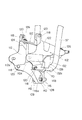
図7は、ハンドル部分100を車体前方から見た図であって、各種配線類を示した正面図である。
ハンドル部分100には、バーハンドル57及び支持部材102に取り付けられた各種機器類に接続される配線が引き回されることになる。そのため、支持部材102は、各配線経路を考慮して外形状が形成されている。
FIG. 7 is a view of the
In the
図7に示すように、支持部材102には、ブリーザーホース109を通すための穴部160が形成されている。また、支持部材102には、メーター類60の配線ケーブル168を通す穴部162(配線経路)が形成されている。さらに、支持部材102には、ヘッドライト59の配線ケーブル170を通す穴部172(配線経路。図2参照)が形成されている。
As shown in FIG. 7, the
また、第1腕部110及び第2腕部112の下側部分は、図7に示すように、固定部116に向かって中央へすぼまる態様で傾斜が付けられており、スロットルレバー104の配線ケーブル164及びリアブレーキ106の配線ケーブル166がこの傾斜部分を通って下側に引き回されている。
Further, as shown in FIG. 7, the lower portions of the
本発明の実施の形態に係る鞍乗り型車両のヘッドライト支持構造によれば、支持部材102は、バーハンドル57に設けられたブラケット140に固定される固定部116と、バーハンドル57を上方から覆う第1保持部130と、バーハンドル57を前方から覆う第2保持部132とを有し、固定部116によりバーハンドル57のブラケット140に固定すると共に、第1保持部及130び第2保持部132をバーハンドル57に隙間136、138をあけて保持させることでバーハンドル57に支持部材102を支持しているので、第1保持部130及び第2保持部132をバーハンドル57の上方および前方から位置を合わせるだけで、第1保持部130及び第2保持部132をボルト等で固定せずに取り付けることができる。これにより、バーハンドル57に支持部材102を容易に取り付けることができる。また、支持部材102に車体上方または前方からの荷重が作用したとしても、支持部材102が撓み、第1保持部130及び第2保持部132がバーハンドル57と接触して荷重を受けるので、ヘッドライト59の取付に必要な強度を確保することができる。
また、支持部材102の前部に左右から前方に延びる第1腕部110と第2腕部112とによってヘッドライト59を支持させているので、ヘッドライト59の着脱作業を容易に行うことができる。
According to the headlight support structure for a saddle-ride type vehicle according to the embodiment of the present invention, the
Further, since the
また、第1保持部130の近傍で、支持部材102とバーハンドル57との間に防振ゴム154を介在させているので、支持部材102とバーハンドル57とを防振ゴム154で防振させることができ、車体の振動等が支持部材102に伝わらないようにすることができる。その結果、ヘッドライト59に作用する負荷を軽減させることができる。
Further, since the
さらに、支持部材102を樹脂材料で成型し、この支持部材102に、第1腕部110、第2腕部112、フランジ部122、ヘッドライト59の配線ケーブル170を通す穴部172、及びメーター類60の配線ケーブル168を通す穴部162一体に成形しているので、ハンドル部分100に取り付ける各装備を1つの支持部材102で取り付けることができ、各装置を取り付けるために個々に支持部材を設ける場合と比較して、各装備の取り付け作業を容易に行うことができる。また、配線ケーブル168、170をコンパクトにまとめることができ、外観性を向上させることができる。
Further, the
また、第1腕部110及び第2腕部112の下側部分は、固定部116に向かって中央へすぼまる態様で傾斜が付けられており、スロットルレバー104の配線ケーブル164及びリアブレーキ106の配線ケーブル166がこの傾斜部分を通って下側に引き回されているので、これらの配線ケーブル164、166をハンドル部分100にコンパクトにまとめて引き回すことで、配線ケーブル164、166が外側から見え難いようにして、外観性を向上させることができる。
Further, the lower portions of the
以上、本発明の実施の形態について述べたが、本発明の技術思想に基づいて各種の変形および変更が可能である。
本実施の形態では、不整地を走行可能なATV型車両について説明したが、バーハンドル57を有し、このバーハンドル57にヘッドライト59を取り付ける態様の車両であれば、自動2輪車にも適用することができる。これにより、ハンドル部分100の部品を容易に取り付けることができると共に、配線類が外側から煩雑に見えないようにして外観性を向上させた自動2輪車を提供することができる。
While the embodiments of the present invention have been described above, various modifications and changes can be made based on the technical idea of the present invention.
In the present embodiment, an ATV type vehicle capable of traveling on rough terrain has been described. However, a motorcycle having a
10 鞍乗り型不整地走行車両(鞍乗り型車両)
11 車体フレーム
12 エンジン
17 前輪
18 後輪
21 ステアリング装置
34 燃料タンク
56 ステアリングシャフト
57 バーハンドル
58 ヘッドライトカバー
58a 前側カバー
58b 後側カバー
59 ヘッドライト
60 メーター類
100 ハンドル部分
102 支持部材
104 スロットルレバー
106 リアブレーキ
108 イグニッションスイッチ
109 ブリーザーホース
110 第1腕部
110a、112a 突起部
112 第2腕部
114 後壁部
116 固定部
116a 平面部
118、126 グロメット
120 固定穴
122 フランジ部(メーター類支持部)
124 固定穴
126 グロメット
128 取付穴
130 第1保持部
130a 溝部
132 第2保持部
132a 切り欠き部
136、138 隙間
140 ブラケット
142 ボルト
148 防振ゴム(弾性部材)
150 平面部
160、162、172 穴部(配線経路)
164、166、168、170 配線ケーブル
10 Saddle-type rough terrain vehicle (saddle-type vehicle)
DESCRIPTION OF SYMBOLS 11 Body frame 12
124
150
164, 166, 168, 170 Wiring cable
Claims (3)
前記支持部材は、前記バーハンドルに設けられたブラケットに固定される固定部と、前記バーハンドルを上方から覆う第1保持部と、前記バーハンドルを前方から覆う第2保持部とを有し、前記固定部によりバーハンドルのブラケットに固定されると共に、第1保持部及び第2保持部をバーハンドルに隙間をあけて保持させることでバーハンドルに支持され、
前記支持部材の前部の左右から前方に延びる第1腕部と第2腕部とによってヘッドライトを支持させたことを特徴とする鞍乗り型車両のヘッドライト支持構造。 In a saddle-ride type vehicle including a support member that supports a headlight on a bar handle that steers a front wheel, and a headlight cover that is supported by the support member so as to cover the headlight.
The support member includes a fixing part fixed to a bracket provided on the bar handle, a first holding part that covers the bar handle from above, and a second holding part that covers the bar handle from the front, It is fixed to the bracket of the bar handle by the fixing part, and supported by the bar handle by holding the first holding part and the second holding part with a gap in the bar handle,
A headlight support structure for a saddle-ride type vehicle, wherein the headlight is supported by a first arm portion and a second arm portion extending forward from the left and right of the front portion of the support member.
Priority Applications (3)
| Application Number | Priority Date | Filing Date | Title |
|---|---|---|---|
| JP2008071657A JP5098103B2 (en) | 2008-03-19 | 2008-03-19 | Headlight support structure for saddle-ride type vehicles |
| CA2648828A CA2648828C (en) | 2008-03-19 | 2009-01-08 | Headlight support structure for saddle-riding type vehicle |
| US12/378,141 US8104937B2 (en) | 2008-03-19 | 2009-02-11 | Headlight support structure for a saddle-type vehicle |
Applications Claiming Priority (1)
| Application Number | Priority Date | Filing Date | Title |
|---|---|---|---|
| JP2008071657A JP5098103B2 (en) | 2008-03-19 | 2008-03-19 | Headlight support structure for saddle-ride type vehicles |
Publications (2)
| Publication Number | Publication Date |
|---|---|
| JP2009226975A JP2009226975A (en) | 2009-10-08 |
| JP5098103B2 true JP5098103B2 (en) | 2012-12-12 |
Family
ID=41088739
Family Applications (1)
| Application Number | Title | Priority Date | Filing Date |
|---|---|---|---|
| JP2008071657A Expired - Fee Related JP5098103B2 (en) | 2008-03-19 | 2008-03-19 | Headlight support structure for saddle-ride type vehicles |
Country Status (3)
| Country | Link |
|---|---|
| US (1) | US8104937B2 (en) |
| JP (1) | JP5098103B2 (en) |
| CA (1) | CA2648828C (en) |
Families Citing this family (6)
| Publication number | Priority date | Publication date | Assignee | Title |
|---|---|---|---|---|
| JP4986684B2 (en) * | 2007-03-30 | 2012-07-25 | 本田技研工業株式会社 | Saddle riding four-wheeled vehicle |
| JP5186469B2 (en) * | 2009-11-26 | 2013-04-17 | 本田技研工業株式会社 | Headlight support structure for saddle-ride type vehicles |
| JP6130222B2 (en) | 2013-05-24 | 2017-05-17 | 川崎重工業株式会社 | Motorcycle harness support structure |
| CN206155644U (en) * | 2016-10-13 | 2017-05-10 | 江门市大长江集团有限公司 | Motorcycle locomotive structure |
| WO2018159014A1 (en) * | 2017-02-28 | 2018-09-07 | 本田技研工業株式会社 | Meter attachment structure for saddle-ridden vehicle |
| US12005986B2 (en) * | 2022-04-27 | 2024-06-11 | Nathan Burnell | Motorcycle headlight |
Family Cites Families (13)
| Publication number | Priority date | Publication date | Assignee | Title |
|---|---|---|---|---|
| JPS575264Y2 (en) * | 1976-07-28 | 1982-02-01 | ||
| JPS5541671Y2 (en) * | 1977-12-07 | 1980-09-29 | ||
| US4390927A (en) * | 1982-05-19 | 1983-06-28 | Von Feldt Donald E | Bicycle flashlight holder |
| JPS5973332A (en) * | 1982-10-18 | 1984-04-25 | Honda Motor Co Ltd | Headlight apparatus for motorcycle and the like |
| JP2625800B2 (en) | 1988-01-06 | 1997-07-02 | ヤマハ株式会社 | Automatic performance device |
| JP2992096B2 (en) * | 1991-01-21 | 1999-12-20 | ヤマハ発動機株式会社 | Motorcycle handlebar surrounding structure |
| JP3288828B2 (en) * | 1993-10-19 | 2002-06-04 | 本田技研工業株式会社 | Mounting structure for headlights of vehicles such as motorcycles |
| JPH10250660A (en) * | 1997-03-11 | 1998-09-22 | O G K Giken Kk | Front basket of bicycle for children |
| JP4104198B2 (en) * | 1998-01-30 | 2008-06-18 | 本田技研工業株式会社 | Motorcycle headlight and speedometer mounting device |
| JP4232997B2 (en) * | 1999-03-31 | 2009-03-04 | 本田技研工業株式会社 | Motorcycle steering device |
| JP2003011719A (en) | 2001-06-28 | 2003-01-15 | Suzuki Motor Corp | Vehicle headlamp mounting structure |
| US7104236B2 (en) * | 2003-09-30 | 2006-09-12 | Honda Motor Co., Ltd. | Intake air management apparatus for a vehicle, and motorcycle including same |
| JP4849458B2 (en) * | 2006-08-31 | 2012-01-11 | 本田技研工業株式会社 | Meter support structure |
-
2008
- 2008-03-19 JP JP2008071657A patent/JP5098103B2/en not_active Expired - Fee Related
-
2009
- 2009-01-08 CA CA2648828A patent/CA2648828C/en not_active Expired - Fee Related
- 2009-02-11 US US12/378,141 patent/US8104937B2/en active Active
Also Published As
| Publication number | Publication date |
|---|---|
| CA2648828C (en) | 2012-05-08 |
| CA2648828A1 (en) | 2009-09-19 |
| US8104937B2 (en) | 2012-01-31 |
| US20090237948A1 (en) | 2009-09-24 |
| JP2009226975A (en) | 2009-10-08 |
Similar Documents
| Publication | Publication Date | Title |
|---|---|---|
| JP5478307B2 (en) | Braking device for saddle-ride type vehicles | |
| JP5129632B2 (en) | Harness holding structure for saddle-ride type vehicles | |
| JP6404308B2 (en) | Saddle riding vehicle | |
| JP5098103B2 (en) | Headlight support structure for saddle-ride type vehicles | |
| US7637342B2 (en) | Straddle type vehicle | |
| WO2013179501A1 (en) | Saddle-type vehicle | |
| CN110015368B (en) | saddle riding vehicle | |
| JP2016117349A (en) | Saddle-riding type vehicle | |
| JP5871382B2 (en) | Harness arrangement structure for saddle riding type vehicles | |
| JP2008300107A (en) | vehicle | |
| JP2016182838A (en) | Saddle riding vehicle | |
| US10442491B2 (en) | Straddle-type vehicle | |
| JP4535943B2 (en) | Arrangement structure of vehicle engine accessories | |
| JP2010203388A (en) | Electrical component arrangement structure | |
| JP2009090887A (en) | Saddle riding vehicle | |
| JP7273605B2 (en) | Straddle vehicle | |
| JP5566654B2 (en) | Motorcycle wiring system | |
| CN110015369A (en) | saddle riding vehicle | |
| JP2016068828A (en) | Front structure of motorcycle | |
| JP3157690U (en) | Saddle riding vehicle | |
| JP7712814B2 (en) | Meter bracket for straddle-type vehicles | |
| JP7369749B2 (en) | saddle type vehicle | |
| JP7340576B2 (en) | saddle type vehicle | |
| CN223266964U (en) | Saddle-type vehicles | |
| JP7730879B2 (en) | Saddle-type vehicle |
Legal Events
| Date | Code | Title | Description |
|---|---|---|---|
| A621 | Written request for application examination |
Free format text: JAPANESE INTERMEDIATE CODE: A621 Effective date: 20101126 |
|
| A977 | Report on retrieval |
Free format text: JAPANESE INTERMEDIATE CODE: A971007 Effective date: 20120417 |
|
| TRDD | Decision of grant or rejection written | ||
| A01 | Written decision to grant a patent or to grant a registration (utility model) |
Free format text: JAPANESE INTERMEDIATE CODE: A01 Effective date: 20120828 |
|
| A01 | Written decision to grant a patent or to grant a registration (utility model) |
Free format text: JAPANESE INTERMEDIATE CODE: A01 |
|
| A61 | First payment of annual fees (during grant procedure) |
Free format text: JAPANESE INTERMEDIATE CODE: A61 Effective date: 20120906 |
|
| FPAY | Renewal fee payment (event date is renewal date of database) |
Free format text: PAYMENT UNTIL: 20151005 Year of fee payment: 3 |
|
| R150 | Certificate of patent or registration of utility model |
Ref document number: 5098103 Country of ref document: JP Free format text: JAPANESE INTERMEDIATE CODE: R150 Free format text: JAPANESE INTERMEDIATE CODE: R150 |
|
| LAPS | Cancellation because of no payment of annual fees |