JP5097713B2 - LIGHTING DEVICE AND LIGHTING DEVICE MANUFACTURING METHOD - Google Patents
LIGHTING DEVICE AND LIGHTING DEVICE MANUFACTURING METHOD Download PDFInfo
- Publication number
- JP5097713B2 JP5097713B2 JP2008545158A JP2008545158A JP5097713B2 JP 5097713 B2 JP5097713 B2 JP 5097713B2 JP 2008545158 A JP2008545158 A JP 2008545158A JP 2008545158 A JP2008545158 A JP 2008545158A JP 5097713 B2 JP5097713 B2 JP 5097713B2
- Authority
- JP
- Japan
- Prior art keywords
- collimator
- lighting device
- led
- led device
- heat transfer
- Prior art date
- Legal status (The legal status is an assumption and is not a legal conclusion. Google has not performed a legal analysis and makes no representation as to the accuracy of the status listed.)
- Active
Links
Images


Classifications
-
- F—MECHANICAL ENGINEERING; LIGHTING; HEATING; WEAPONS; BLASTING
- F21—LIGHTING
- F21S—NON-PORTABLE LIGHTING DEVICES; SYSTEMS THEREOF; VEHICLE LIGHTING DEVICES SPECIALLY ADAPTED FOR VEHICLE EXTERIORS
- F21S45/00—Arrangements within vehicle lighting devices specially adapted for vehicle exteriors, for purposes other than emission or distribution of light
- F21S45/40—Cooling of lighting devices
- F21S45/47—Passive cooling, e.g. using fins, thermal conductive elements or openings
- F21S45/48—Passive cooling, e.g. using fins, thermal conductive elements or openings with means for conducting heat from the inside to the outside of the lighting devices, e.g. with fins on the outer surface of the lighting device
-
- F—MECHANICAL ENGINEERING; LIGHTING; HEATING; WEAPONS; BLASTING
- F21—LIGHTING
- F21V—FUNCTIONAL FEATURES OR DETAILS OF LIGHTING DEVICES OR SYSTEMS THEREOF; STRUCTURAL COMBINATIONS OF LIGHTING DEVICES WITH OTHER ARTICLES, NOT OTHERWISE PROVIDED FOR
- F21V29/00—Protecting lighting devices from thermal damage; Cooling or heating arrangements specially adapted for lighting devices or systems
- F21V29/50—Cooling arrangements
- F21V29/51—Cooling arrangements using condensation or evaporation of a fluid, e.g. heat pipes
-
- F—MECHANICAL ENGINEERING; LIGHTING; HEATING; WEAPONS; BLASTING
- F21—LIGHTING
- F21V—FUNCTIONAL FEATURES OR DETAILS OF LIGHTING DEVICES OR SYSTEMS THEREOF; STRUCTURAL COMBINATIONS OF LIGHTING DEVICES WITH OTHER ARTICLES, NOT OTHERWISE PROVIDED FOR
- F21V29/00—Protecting lighting devices from thermal damage; Cooling or heating arrangements specially adapted for lighting devices or systems
- F21V29/50—Cooling arrangements
- F21V29/56—Cooling arrangements using liquid coolants
- F21V29/58—Cooling arrangements using liquid coolants characterised by the coolants
-
- F—MECHANICAL ENGINEERING; LIGHTING; HEATING; WEAPONS; BLASTING
- F21—LIGHTING
- F21V—FUNCTIONAL FEATURES OR DETAILS OF LIGHTING DEVICES OR SYSTEMS THEREOF; STRUCTURAL COMBINATIONS OF LIGHTING DEVICES WITH OTHER ARTICLES, NOT OTHERWISE PROVIDED FOR
- F21V29/00—Protecting lighting devices from thermal damage; Cooling or heating arrangements specially adapted for lighting devices or systems
- F21V29/50—Cooling arrangements
- F21V29/70—Cooling arrangements characterised by passive heat-dissipating elements, e.g. heat-sinks
- F21V29/74—Cooling arrangements characterised by passive heat-dissipating elements, e.g. heat-sinks with fins or blades
- F21V29/76—Cooling arrangements characterised by passive heat-dissipating elements, e.g. heat-sinks with fins or blades with essentially identical parallel planar fins or blades, e.g. with comb-like cross-section
- F21V29/763—Cooling arrangements characterised by passive heat-dissipating elements, e.g. heat-sinks with fins or blades with essentially identical parallel planar fins or blades, e.g. with comb-like cross-section the planes containing the fins or blades having the direction of the light emitting axis
-
- F—MECHANICAL ENGINEERING; LIGHTING; HEATING; WEAPONS; BLASTING
- F21—LIGHTING
- F21V—FUNCTIONAL FEATURES OR DETAILS OF LIGHTING DEVICES OR SYSTEMS THEREOF; STRUCTURAL COMBINATIONS OF LIGHTING DEVICES WITH OTHER ARTICLES, NOT OTHERWISE PROVIDED FOR
- F21V29/00—Protecting lighting devices from thermal damage; Cooling or heating arrangements specially adapted for lighting devices or systems
- F21V29/50—Cooling arrangements
- F21V29/70—Cooling arrangements characterised by passive heat-dissipating elements, e.g. heat-sinks
- F21V29/74—Cooling arrangements characterised by passive heat-dissipating elements, e.g. heat-sinks with fins or blades
- F21V29/76—Cooling arrangements characterised by passive heat-dissipating elements, e.g. heat-sinks with fins or blades with essentially identical parallel planar fins or blades, e.g. with comb-like cross-section
- F21V29/767—Cooling arrangements characterised by passive heat-dissipating elements, e.g. heat-sinks with fins or blades with essentially identical parallel planar fins or blades, e.g. with comb-like cross-section the planes containing the fins or blades having directions perpendicular to the light emitting axis
-
- F—MECHANICAL ENGINEERING; LIGHTING; HEATING; WEAPONS; BLASTING
- F21—LIGHTING
- F21V—FUNCTIONAL FEATURES OR DETAILS OF LIGHTING DEVICES OR SYSTEMS THEREOF; STRUCTURAL COMBINATIONS OF LIGHTING DEVICES WITH OTHER ARTICLES, NOT OTHERWISE PROVIDED FOR
- F21V29/00—Protecting lighting devices from thermal damage; Cooling or heating arrangements specially adapted for lighting devices or systems
- F21V29/50—Cooling arrangements
- F21V29/70—Cooling arrangements characterised by passive heat-dissipating elements, e.g. heat-sinks
- F21V29/74—Cooling arrangements characterised by passive heat-dissipating elements, e.g. heat-sinks with fins or blades
- F21V29/77—Cooling arrangements characterised by passive heat-dissipating elements, e.g. heat-sinks with fins or blades with essentially identical diverging planar fins or blades, e.g. with fan-like or star-like cross-section
- F21V29/777—Cooling arrangements characterised by passive heat-dissipating elements, e.g. heat-sinks with fins or blades with essentially identical diverging planar fins or blades, e.g. with fan-like or star-like cross-section the planes containing the fins or blades having directions perpendicular to the light emitting axis
-
- F—MECHANICAL ENGINEERING; LIGHTING; HEATING; WEAPONS; BLASTING
- F21—LIGHTING
- F21V—FUNCTIONAL FEATURES OR DETAILS OF LIGHTING DEVICES OR SYSTEMS THEREOF; STRUCTURAL COMBINATIONS OF LIGHTING DEVICES WITH OTHER ARTICLES, NOT OTHERWISE PROVIDED FOR
- F21V29/00—Protecting lighting devices from thermal damage; Cooling or heating arrangements specially adapted for lighting devices or systems
- F21V29/85—Protecting lighting devices from thermal damage; Cooling or heating arrangements specially adapted for lighting devices or systems characterised by the material
-
- F—MECHANICAL ENGINEERING; LIGHTING; HEATING; WEAPONS; BLASTING
- F21—LIGHTING
- F21Y—INDEXING SCHEME ASSOCIATED WITH SUBCLASSES F21K, F21L, F21S and F21V, RELATING TO THE FORM OR THE KIND OF THE LIGHT SOURCES OR OF THE COLOUR OF THE LIGHT EMITTED
- F21Y2115/00—Light-generating elements of semiconductor light sources
- F21Y2115/10—Light-emitting diodes [LED]
-
- H—ELECTRICITY
- H01—ELECTRIC ELEMENTS
- H01L—SEMICONDUCTOR DEVICES NOT COVERED BY CLASS H10
- H01L2924/00—Indexing scheme for arrangements or methods for connecting or disconnecting semiconductor or solid-state bodies as covered by H01L24/00
- H01L2924/0001—Technical content checked by a classifier
- H01L2924/0002—Not covered by any one of groups H01L24/00, H01L24/00 and H01L2224/00
-
- H—ELECTRICITY
- H01—ELECTRIC ELEMENTS
- H01L—SEMICONDUCTOR DEVICES NOT COVERED BY CLASS H10
- H01L33/00—Semiconductor devices with at least one potential-jump barrier or surface barrier specially adapted for light emission; Processes or apparatus specially adapted for the manufacture or treatment thereof or of parts thereof; Details thereof
- H01L33/48—Semiconductor devices with at least one potential-jump barrier or surface barrier specially adapted for light emission; Processes or apparatus specially adapted for the manufacture or treatment thereof or of parts thereof; Details thereof characterised by the semiconductor body packages
- H01L33/64—Heat extraction or cooling elements
- H01L33/648—Heat extraction or cooling elements the elements comprising fluids, e.g. heat-pipes
Description
本発明は、照明装置及びそのような装置を製造する方法に関する。 The present invention relates to a lighting device and a method of manufacturing such a device.
最近、LEDのような半導体発光装置が、自動車及び一般照明用途のために使用されている。極めて高い光束を示す所謂「高出力」LEDの最近の開発は、照明用途のための一般的な電球の代わりに単一のLEDを使用することを可能にしている。 Recently, semiconductor light emitting devices such as LEDs have been used for automotive and general lighting applications. Recent developments of so-called “high power” LEDs that exhibit very high luminous flux have made it possible to use a single LED instead of a common light bulb for lighting applications.
一方では、高光束、これらの装置の対応する高電力消費(>1W)、及び、スモールフォームファクタの故に、装置によって生成される熱は適切に放散されなければならない。何故ならば、LEDの効率は、高温で極めて影響を受けるからである。他方では、コリメータ又は反射器のような光学系が、特殊の用途によって、例えば、自動車ヘッドライトにおいて要求されるように光を方向付ける多くの用途で使用される。従来技術において、この問題は、普通、剛的なヒートシンクと反射器との間のLEDの配置によって取り組まれる。しかしながら、2つの素子間のLEDの剛的な取付の故に、力がLEDに加えられ、それらは特に自動車用途における発光装置に損傷を与え得る。 On the one hand, due to the high luminous flux, the corresponding high power consumption (> 1 W) of these devices, and the small form factor, the heat generated by the devices must be dissipated appropriately. This is because the efficiency of the LED is highly affected at high temperatures. On the other hand, optical systems such as collimators or reflectors are used in many applications to direct light as required by special applications, for example in automotive headlights. In the prior art, this problem is usually addressed by the placement of the LED between a rigid heat sink and a reflector. However, because of the rigid attachment of the LED between the two elements, forces are applied to the LED, which can damage the light emitting device, particularly in automotive applications.
DE102005013208は、少なくとも1つのLEDを備える冷却LEDランプを開示しており、LEDは、筐体から構成され、LEDは、筐体内で透明冷却媒体内に含まれている。DE10213042A1は、流体が筐体内に恒久的に留まるよう、流体で充填された緊密に封止された筐体を有するランプを開示している。流体は、環境空気よりも高い熱吸収性を有する。 DE102005013208 discloses a cooled LED lamp comprising at least one LED, the LED being composed of a housing, which is contained in a transparent cooling medium within the housing. DE10213042A1 discloses a lamp having a tightly sealed housing filled with fluid so that the fluid remains permanently in the housing. The fluid has a higher heat absorption than ambient air.
EP1225643A1は、半導体本体と、反射素子とを含む、片側性発光装置を開示している。半導体本体は、その全ての表面から放射線を放射する。放射される光は、反射素子による方向変更後、単一ビームに集められる。反射素子は、反射される光を半導体本体に沿って方向変更する。 EP1225643A1 discloses a one-sided light emitting device including a semiconductor body and a reflective element. The semiconductor body emits radiation from all its surfaces. The emitted light is collected in a single beam after being redirected by the reflective element. The reflective element changes the direction of the reflected light along the semiconductor body.
上述の問題に対する解決策が、WO−A−2004/038759に開示されている。図11から見られるように、LED10は、LED10内で生成される熱を放散するために使用されるヒートパイプ64の頂部に取り付けられている。全反射(TIR)反射器10bが、LED10に接触しない状態で、頂部に配置され、2つの素子間に凹状空間を形成している。TIR反射器10bとLED10との間の凹状空間は、屈折率整合流体で充填されている。
A solution to the above problem is disclosed in WO-A-2004 / 038759. As can be seen from FIG. 11, the
しかしながら、この種類の照明装置は、高温で装置を壊し得る屈折率整合流体、LED、及び、TIR反射器の異なる熱膨張係数の問題の故に、限定的な寿命を有し得る。さらに、従来技術装置の屈折率整合流体は、劣化問題を引き起こし、充填プロセスは、装置の製造を困難にする。 However, this type of lighting device may have a limited life due to the different thermal expansion coefficient issues of index matching fluids, LEDs, and TIR reflectors that can break the device at high temperatures. In addition, the index matching fluids of prior art devices cause degradation problems and the filling process makes the device difficult to manufacture.
従って、本発明の目的は、強化された機械的支持を示すと同時に、良好な熱放散を維持する照明装置を提供することである。 Accordingly, it is an object of the present invention to provide a lighting device that exhibits enhanced mechanical support while maintaining good heat dissipation.
本目的は、請求項1に従った照明装置及び請求項10に従った照明装置の製造方法によって本発明に従って解決される。従属項は本発明の好適実施態様に関する。
This object is solved according to the invention by a lighting device according to claim 1 and a method for manufacturing a lighting device according to
本発明に従った照明装置は、少なくとも1つのLED装置を含み、複数のLED装置を含み得る。LED装置は、少なくとも1つの半導体発光装置(LED)、好ましくは、照明目的のために製造される高出力LEDを含む。代替的に、複数のLEDは、高い光束を達成するために、例えば、単一のLEDダイ又は複数のLEDダイス上の配列の形態の単一LED装置内で使用され得る。さらに、LED装置は、駆動回路又はLEDに電気エネルギを供給するための電線のような他の電気的若しくは機械的な構成部品、LEDを支持するための取付体、又は、熱放散のための手段を含み得る。LED装置は、コリメータにのみ剛的に結合される。「剛的に結合される」という用語は、本発明を用いて、例えば、振動の形態の力をLED装置に適用することを可能にする如何なる種類の接続又は固定をも含む。コリメータのみへの剛的な結合、即ち、LED装置を電源装置が単一の構成部品又は地点にのみ剛的に接続されることは、有利である。何故ならば、例えば、振動の故に自動車用途において起こる実質的な力が、LED装置に適用され得るからである。実質的な力は、例えば、振動による強制的破裂又は破損の関するLED装置又はLED装置の如何なる構成部品をも損傷し得る力を含むものと理解される。コリメータは、如何なる種類でもあり得る。例えば、イオン交換ガラス材料から成るGRINレンズ(屈折率分布型レンズ)が使用され得る。一般的には、コリメータは、如何なる適切な材料、例えば、プラスチック又はガラスからも製造され得る。現在の脈絡において、「コリメータ」という用語は、如何なる適切な種類の反射器をも含むものと理解される。コリメータは、コリメータを維持するのに十分な安定性をもたらし得る、如何なる材料からの製造され得る、筐体内に少なくとも部分的に取り付けられる。例えば、金属又はプラスチック材料が使用される。筐体は、熱伝導性材料で製造されることによって或いは冷却フィンのような適切な構造手段によって、LEDによって生成される熱を放散し得ることが好ましい。筐体内に別個のLED装置又は共通のLEDを備える複数のコリメータを配置することが可能である。 The lighting device according to the present invention comprises at least one LED device and may comprise a plurality of LED devices. The LED device includes at least one semiconductor light emitting device (LED), preferably a high power LED manufactured for lighting purposes. Alternatively, multiple LEDs can be used in a single LED device, for example in the form of a single LED die or an array on multiple LED dies, to achieve high luminous flux. In addition, the LED device may comprise a drive circuit or other electrical or mechanical component such as an electrical wire for supplying electrical energy to the LED, a mounting for supporting the LED, or a means for heat dissipation. Can be included. The LED device is rigidly coupled only to the collimator. The term “rigidly coupled” includes any type of connection or fixation that allows the present invention to be applied to a LED device, for example, in the form of vibration. It is advantageous to have a rigid coupling to the collimator only, i.e. the LED device is rigidly connected to the power supply only at a single component or point. This is because, for example, substantial forces that occur in automotive applications due to vibration can be applied to the LED device. Substantial forces are understood to include, for example, forces that can damage an LED device or any component of the LED device with respect to forced rupture or breakage due to vibration. The collimator can be of any type. For example, a GRIN lens (gradient index lens) made of an ion exchange glass material can be used. In general, the collimator can be manufactured from any suitable material, such as plastic or glass. In the current context, the term “collimator” is understood to include any suitable type of reflector. The collimator is mounted at least partially within the housing, which can be manufactured from any material that can provide sufficient stability to maintain the collimator. For example, a metal or plastic material is used. The housing is preferably capable of dissipating heat generated by the LEDs by being made of a thermally conductive material or by suitable structural means such as cooling fins. It is possible to arrange a plurality of collimators with separate LED devices or common LEDs in the housing.
本発明によれば、筐体はキャビティを含み、非剛的な熱移転媒体がキャビティ内に収容される。キャビティは、如何なる形状及び容積でもあり得るし、LED装置が熱移転媒体内に少なくとも部分的に収容されるよう、熱移転媒体に依存して寸法取られる。従って、コリメータは、相応して筐体に取り付けられる。一般的には、LED装置と熱移転媒体との間の良好な熱接触が望ましい。キャビティは、好ましくは、熱移転媒体が発光装置の寿命に亘ってキャビティ内に保持されるよう完全に封止される。 According to the present invention, the housing includes a cavity, and a non-rigid heat transfer medium is contained in the cavity. The cavity can be any shape and volume and is dimensioned depending on the heat transfer medium so that the LED device is at least partially housed within the heat transfer medium. The collimator is accordingly attached to the housing accordingly. In general, good thermal contact between the LED device and the heat transfer medium is desirable. The cavity is preferably completely sealed so that the heat transfer medium is retained in the cavity for the lifetime of the light emitting device.
非剛的な熱移転媒体は、LED装置内で生成される熱を放散するよう熱伝導性である如何なる種類でもあり得る。「非剛的な」という用語は、LED装置への硬い接続を形成しない、即ち、媒体がLED装置に実質的な力を伝えない全ての材料を含むものと理解される。基本的な考えは、上述のように、如何なる力もLED装置に適用されないよう、LED装置がコリメータのみに、即ち、単一の構成部品に剛的に接続されることであり、さもなければ、それはLED装置を損傷し得る。 The non-rigid heat transfer medium can be of any type that is thermally conductive to dissipate the heat generated within the LED device. The term “non-rigid” is understood to include all materials that do not form a rigid connection to the LED device, ie, the media does not transmit substantial force to the LED device. The basic idea is that, as mentioned above, the LED device is rigidly connected only to the collimator, i.e. to a single component, so that no force is applied to the LED device; It can damage the LED device.
好適実施態様において、コリメータは、TIR(全反射)コリメータであり、TIR反射器とも呼ばれる。TIRコリメータは、良好なコリメーション特性を可能にし、高い光学効率をもたらす。普通50%の効率を示す標準的な反射器と比較すると、TIRコリメータは、>90%の効率をもたらす。一般的には、TIRコリメータは、使用される波長範囲に依存して、如何なる適切な材料からも製造され得る。適切な材料は、一例として、ガラス又は透明セラミック材料である。製造の容易さに関しては、TIRコリメータが透明プラスチックから製造されることが特に好ましい。適切なプラスチック材料は、PMMA(ポリメタクリル酸メチル)、ポリカーボネート、又は、COC(環状オレフィン共重合体)を含む。TIRコリメータは、光学効率をさらに強化するために、用途に依存して、全反射を支持するよう、所望の波長範囲にある反射性塗膜又はクラッディングによって部分的に塗工され得る。反射性塗膜は、LED装置が取り付けられるTIRコリメータの部分に特に塗布され得る。何故ならば、その地域では、これらの表面上への入射光の角度の故に、全反射を達成することが困難であり得るからである。 In a preferred embodiment, the collimator is a TIR (total reflection) collimator, also called a TIR reflector. TIR collimators allow good collimation characteristics and provide high optical efficiency. Compared to standard reflectors, which usually show 50% efficiency, TIR collimators provide> 90% efficiency. In general, the TIR collimator can be made from any suitable material, depending on the wavelength range used. Suitable materials are, by way of example, glass or transparent ceramic materials. With regard to ease of manufacture, it is particularly preferred that the TIR collimator is manufactured from a transparent plastic. Suitable plastic materials include PMMA (polymethyl methacrylate), polycarbonate, or COC (cyclic olefin copolymer). The TIR collimator can be partially coated with a reflective coating or cladding in the desired wavelength range to support total internal reflection, depending on the application, to further enhance optical efficiency. The reflective coating can be specifically applied to the portion of the TIR collimator where the LED device is attached. This is because in that region it may be difficult to achieve total internal reflection due to the angle of incident light on these surfaces.
本発明によれば、LED装置は、無機接着剤、ガラスフリットを用いて、或いは、射出成形によってコリメータに結合される。従って、コリメータは、適切な保持体を提供しなければ成らず、それは、例えば、コリメータ内に形成される凹部であり得る。LED装置とコリメータとの間に、即ち、光路内に塗布される無機接着剤を使用するときには、接着剤は、好ましくは、コリメータの反射率を満たすべきである。コリメータがガラスから成る場合には、ガラスフリットの使用が好ましい。ここでは、熱及び圧力を用いてLED装置をコリメータに接続するために、コリメータの屈折率を有する流体ガラスフリットが使用される。 According to the present invention, LED devices, an inorganic adhesive, using a glass frit, or Ru is coupled to the collimator by injection molding. Thus, the collimator must provide a suitable holder, which can be, for example, a recess formed in the collimator. When using an inorganic adhesive applied between the LED device and the collimator, i.e. in the light path, the adhesive should preferably meet the reflectivity of the collimator. When the collimator is made of glass, it is preferable to use a glass frit. Here, a fluid glass frit with the refractive index of the collimator is used to connect the LED device to the collimator using heat and pressure.
LED装置は、射出成形を用いてもコリメータに結合され得る。コリメータがプラスチック材料から成る場合には、例えば、TIRコリメータが使用されるときには、この結合が好ましい。射出成形は特に有利である。何故ならば、コリメータとのLEDダイの直接的な接触が達成可能であるので、屈折率の突然の変化に起因する損失が回避され得るからである。よって、TIRコリメータとのLEDの直接的な接触の故の、反射損失の減少とコリメータの全反射特性の組み合わせの故に、特に高い効率が達成され得る。TIRコリメータは、LED装置上に直接的に射出成形され得る。それは容易で費用効率的な製造プロセスを可能にする。 The LED device can also be coupled to the collimator using injection molding. This coupling is preferred when the collimator is made of a plastic material, for example when a TIR collimator is used. Injection molding is particularly advantageous. Because direct contact of the LED die with the collimator can be achieved, losses due to sudden changes in refractive index can be avoided. Thus, particularly high efficiencies can be achieved because of the combination of reduced reflection loss and total reflection properties of the collimator due to direct contact of the LED with the TIR collimator. The TIR collimator can be injection molded directly on the LED device. It allows for an easy and cost effective manufacturing process.
本発明の開発によれば、熱移転媒体は、ゲル状であり、或いは、特に好ましくは、液体である。熱移転媒体は、LED装置と周囲の筐体との間の十分な熱伝導を概ね可能にしなければならない。熱移転媒体はさらに非剛的であるべきであるので、ゲル状又は液体媒体は特に有利である。適切な材料の例は、水、ミネラル、合成油である。熱移転媒体は、熱移転特性を支持する構造、例えば、ゲル状又は液体媒体が内部に存在する多孔性の繊維質構造を備える、上述の種類の組み合わせでもあり得る。熱移転媒体は液体であることが最も好ましい。液体は、一般的に、高密度、よって、良好な熱伝導特性を示す。さらに、液体は、一般的に、LED装置と筐体との間の優れた熱接触をもたらす。LED装置は液体内に浸漬されることが特に好ましい。 According to the development of the invention, the heat transfer medium is in the form of a gel, or particularly preferably a liquid. The heat transfer medium should generally allow for sufficient heat transfer between the LED device and the surrounding housing. Gelled or liquid media are particularly advantageous since the heat transfer media should be further non-rigid. Examples of suitable materials are water, minerals and synthetic oils. The heat transfer medium can also be a combination of the types described above with a structure that supports heat transfer properties, for example a porous fibrous structure in which a gel-like or liquid medium is present. Most preferably, the heat transfer medium is a liquid. Liquids are generally dense and thus exhibit good heat transfer properties. Moreover, the liquid generally provides excellent thermal contact between the LED device and the housing. It is particularly preferred that the LED device is immersed in a liquid.
熱移動機構の種類は、対流型又はヒートパイプ機構のいずれかであり得る。対流型機構のために、適切な液体は、液体媒体が完全に気化しないよう、LED装置の動作温度より上の沸点を有すべきである。気化は、熱放散を妨げる。一般的には、液体は、LED自体又はLED装置の如何なる電気構成部品もが流体と直接的に接触するときに、電気絶縁特性をさらに有さなければならない。しかしながら、LED装置が相応して設計されることを条件として、電源への接続部として伝導性流体が使用され得る。TIRコリメータが使用され、液体がTIRコリメータと直接的に接触するときには、全反射特性を維持するために、TIRコリメータの露出表面をクラッディング又は塗膜で塗工することが必要であり得る。クラッディングの必要性は、本来的には、TIRコリメータ及び使用流体の屈折率の相違に依存する。 The type of heat transfer mechanism can be either a convection type or a heat pipe mechanism. For a convection type mechanism, a suitable liquid should have a boiling point above the operating temperature of the LED device so that the liquid medium does not completely vaporize. Vaporization hinders heat dissipation. In general, the liquid must further have electrical insulation properties when the LED itself or any electrical component of the LED device is in direct contact with the fluid. However, a conductive fluid can be used as a connection to the power supply, provided that the LED device is designed accordingly. When a TIR collimator is used and the liquid is in direct contact with the TIR collimator, it may be necessary to coat the exposed surface of the TIR collimator with a cladding or coating to maintain total reflection properties. The need for cladding is inherently dependent on the difference in refractive index of the TIR collimator and the fluid used.
代替的に、熱移転媒体は、ヒートパイプ流体であり得る。ヒートパイプ流体は、熱を効率的に輸送し得る。ヒートパイプ機構において、流体ヒートパイプ媒体は、熱源と緊密に接触して封止キャビティ内に配置される。熱源で生成される熱の故に、ヒートパイプ流体の一部は気化される。次に、蒸気は、キャビティのより冷たいヒートシンクで凝縮され、次に、熱源に流れ戻り得る。ここでは、ヒートパイプ流体は、LED装置内で生成される熱によって気化される。従って、蒸気は、ヒートシンクとして作用するキャビティの冷たい壁で凝縮し、次に、LED装置に流れ戻る。従って、キャビティは、ヒートパイプ流体の無制約の逆流、よって、還流が可能であるように設計されなければならない。例えば、キャビティの内壁は、逆流が重力によってのみ可能であるように設計され得る。これは、通常、取付位置に依存するので、逆流が重力に抗して向けられるときでさえ、ヒートパイプ流体の還流が維持され得るよう、毛管力によるヒートパイプ流体の逆流を促進するために、好ましくは、多孔性又はウィック状構造がキャビティ内部で使用され得る。特に好ましくは、キャビティの内壁は、ヒートパイプ流体の還流を促進するために、毛管又は動脈状構造を含む。ヒートパイプ流体の十分な気化、よって、LED装置からの熱放散を得るために、LED装置は、多孔性材料に完全に取り囲まれ得ない。 Alternatively, the heat transfer medium can be a heat pipe fluid. A heat pipe fluid can efficiently transport heat. In a heat pipe mechanism, a fluid heat pipe medium is placed in a sealed cavity in intimate contact with a heat source. Because of the heat generated by the heat source, a portion of the heat pipe fluid is vaporized. The vapor can then be condensed with a cooler heat sink in the cavity and then flow back to the heat source. Here, the heat pipe fluid is vaporized by the heat generated in the LED device. Thus, the vapor condenses on the cold wall of the cavity acting as a heat sink and then flows back to the LED device. Thus, the cavity must be designed to allow unrestricted backflow of heat pipe fluid and thus reflux. For example, the inner wall of the cavity can be designed so that backflow is possible only by gravity. This usually depends on the mounting position, so to facilitate the heat pipe fluid back flow due to capillary forces so that the reflux of the heat pipe fluid can be maintained even when the back flow is directed against gravity. Preferably, a porous or wick-like structure can be used inside the cavity. Particularly preferably, the inner wall of the cavity includes a capillary or arterial structure to facilitate the return of the heat pipe fluid. In order to obtain sufficient vaporization of the heat pipe fluid and thus heat dissipation from the LED device, the LED device cannot be completely surrounded by a porous material.
適切なヒートパイプ流体の例は、アンモニア、メタノール、PP2、エタノール、水、又は、これらの溶液又は混合物である。一般的に、適切なヒートパイプ流体は、LED源の温度要件並びに用途の温度条件によって規定される温度範囲内で動作することを許容しなければならない。これは、殆どの場合において、25℃と100℃との間の範囲にある動作温度を意味する。 Examples of suitable heat pipe fluids are ammonia, methanol, PP2, ethanol, water, or solutions or mixtures thereof. In general, a suitable heat pipe fluid must allow operation within the temperature range defined by the temperature requirements of the LED source as well as the temperature conditions of the application. This means an operating temperature in the range between 25 ° C. and 100 ° C. in most cases.
他の好適な実施態様において、筐体のキャビティは、照明装置の取付位置と無関係に、LED装置が液体移転媒体内に少なくとも部分的に収容されるような寸法とされる。この構造は、照明装置の普遍的な動作位置を可能にし、それはより高い使用の柔軟性をもたらす。従って、筐体のキャビティは、LED装置と熱移転媒体との間の十分な熱接触が常に維持されるよう、熱移転媒体の量及び粘性に依存して寸法取られ或いは構成される。 In another preferred embodiment, the cavity of the housing is dimensioned such that the LED device is at least partially housed in the liquid transfer medium, regardless of the mounting position of the lighting device. This structure allows for a universal operating position of the lighting device, which provides greater usage flexibility. Thus, the cavity of the housing is dimensioned or configured depending on the amount and viscosity of the heat transfer medium so that sufficient thermal contact between the LED device and the heat transfer medium is always maintained.
本発明のさらなる開発によれば、LED装置は、ヒートスプレッダを含む。ヒートスプレッダは、熱接触、よって、LED装置から熱移転媒体への熱放散を有利に強化する。ヒートスプレッダは、LED装置がその上に取り付けられ、且つ、一般的に、熱伝導性材料、例えば、DBC(直接接着銅)、セラミックス、シリコン、又は、金属材料から成る小さな取付体であり得る。LEDとヒートスプレッダとの間に、例えば、セラミック又はシリコン材料から成る副取付体を配置することもさらに可能である。ヒートスプレッダは、重量によってLED装置に加えられる力を最小限化するために、出来る限り軽量でなければならない。最も好ましくは、ヒートスプレッダは、コリメータに結合される。 According to a further development of the invention, the LED device comprises a heat spreader. The heat spreader advantageously enhances thermal contact and thus heat dissipation from the LED device to the heat transfer medium. A heat spreader can be a small mounting body on which the LED device is mounted and generally made of a thermally conductive material, such as DBC (Direct Adhesive Copper), ceramics, silicon, or metal material. It is further possible to arrange a submount, for example made of ceramic or silicon material, between the LED and the heat spreader. The heat spreader must be as light as possible to minimize the force applied to the LED device by weight. Most preferably, the heat spreader is coupled to a collimator.
さらなる好適実施態様において、コリメータの表面は、LED装置を電源に接続するよう設計された、LED装置に接続された少なくとも1つの伝導層を含む。伝導層は、CVD又はPVD法を使用して、例えば、プラズマスパッタリングによって、コリメータに塗布され得るし、コリメータの表面の少なくとも一部を被覆し得る。適切な材料は、アルミニウム、銅、又は、銀を含む。熱移転媒体が伝導的であるか、或いは、1つよりも多くの伝導層が形成される場合には、絶縁塗膜、例えば、絶縁ラッカが伝導層に塗布され得る。さらに、伝導層は、前述のように、反射層又はクラッディングとしても機能し得る。伝導層は、電源をLED装置に接続するための様々な可能性を可能にする。例えば、伝導層は、電源の正端子をLED装置に接続し得るのに対し、伝導性の熱移転媒体は、電源の接地端子をLED装置に接続する。さらに、LED装置を電源と接続するために、コリメータ上で互いに分離された2つの伝導層を形成することが可能である。電源の両端子をLED装置に接続し得る構造層をコリメータ上に配置することも可能であり得る。 In a further preferred embodiment, the surface of the collimator comprises at least one conductive layer connected to the LED device, designed to connect the LED device to a power source. The conductive layer can be applied to the collimator using CVD or PVD methods, for example, by plasma sputtering, and can cover at least a portion of the surface of the collimator. Suitable materials include aluminum, copper, or silver. If the heat transfer medium is conductive or more than one conductive layer is formed, an insulating coating, such as an insulating lacquer, can be applied to the conductive layer. Furthermore, the conductive layer can also function as a reflective layer or cladding, as described above. The conductive layer allows various possibilities for connecting the power supply to the LED device. For example, the conductive layer may connect the positive terminal of the power source to the LED device, while the conductive heat transfer medium connects the ground terminal of the power source to the LED device. Furthermore, it is possible to form two conductive layers separated from each other on the collimator in order to connect the LED device to a power source. It may also be possible to arrange on the collimator a structural layer that can connect both terminals of the power supply to the LED device.
適切な電源は、定電流源、抵抗を備える電圧源、バック変圧器、又は、バックブースト変圧器を含む。電源の例は、Zukauskas,et al.,“Introduction to solid state Lighting (2002)”, Chapter 7に開示されている。しかしながら、電源は、単純な電池又は整流幹線接続でもあり得る。 Suitable power sources include constant current sources, voltage sources with resistors, buck transformers, or buck-boost transformers. Examples of power sources are described in Zukauskas, et al. , “Introduction to solid state Lighting (2002)”, Chapter 7. However, the power source can also be a simple battery or a rectifying mains connection.
本発明に従った製造方法によれば、LED装置は、コリメータに剛的に結合される。この方法は、例えば、無機接着剤を用いた、以前に形成されたコリメータへのLED装置の結合を含む。さらに、本方法は、例えば、コリメータがプラスチック材料から成り且つLED装置上に直接的に取り付けられるときに、LED装置への結合と共にコリメータを形成することを含む。 According to the manufacturing method according to the invention, the LED device is rigidly coupled to the collimator. This method includes, for example, coupling the LED device to a previously formed collimator using an inorganic adhesive. Further, the method includes, for example, forming the collimator with a coupling to the LED device when the collimator is made of a plastic material and mounted directly on the LED device.
本発明のこれらの及び他の特徴は、以下に記載される実施態様を参照して明瞭に解明されるであろう。 These and other features of the invention will be clearly elucidated with reference to the embodiments described below.
図面を参照すると、図1は、本発明の第一実施態様に従った照明装置の概略的な側面図を示している。ここでは、PMMA(ポリメタクリル酸メチル)から成るTIRコリメータ2が、筐体3内に取り付けられている。コリメータ2の発光前面は、エポキシ接着剤を使用して筐体3の上方部分に取り付けられているので、筐体3及びコリメータ2は、コリメータ2の回りに延在する封止キャビティ12を形成する。筐体は、照明装置1内で生成される熱を放散するために、幾つかの頭部フィン4を含む。LEDダイ6とヒートスプレッダ7とを含むLED装置5が、コリメータ2の下方部分に剛的に取り付けられている。剛的な接続を構築するために、高分子PMMA材料から成るコリメータ2は、LED装置5上に直接的に射出成形される。コリメータ2のPMMA原料は、LED装置5に塗布されるとき流体であるので、完全なフォームフィットが達成される。よって、光路内に空隙は存在せず、その結果、結合損失の減少の故に、高い光学効率が得られる。
Referring to the drawings, FIG. 1 shows a schematic side view of a lighting device according to a first embodiment of the present invention. Here, a
LEDダイ6は、LED駆動用の幾つかの電気回路を含む。LEDダイ6は、コリメータ2の表面の部分の上に設けられる層構造8内に設けられる伝導層13を使用して、電源(図示せず)に電気的に接続されている。コリメータ2の表面の残余部分は、発光前面を除き、クラッディング(図示せず)で被覆されているので、コリメータ2がキャビティ12内に設けられるヒートパイプ流体10と直接接触するときに、全反射特性が常に維持される。ここでは、エタノールがヒートパイプ流体10として使用される。
The LED die 6 includes several electrical circuits for driving the LEDs. The LED die 6 is electrically connected to a power source (not shown) using a
伝導層13は、電源に接続する電線9に接続されている。層構造8の構造の実施態様が、図6a及び6bに示されており、以下に説明される。ヒートスプレッダ7は、DBC(直接接着銅)から成り、キャビティ12内に設けられるヒートパイプ流体10への熱接触を強化するために使用され、LEDダイ5はそこに部分的に浸漬される。
The
動作中にLEDダイ6によって生成される熱の筐体3の外側への輸送を達成するために、ヒートパイプ流体10は加熱され、LED装置5によって気化される。ヒートパイプ流体10の熱い蒸気は、筐体3及び/又はコリメータ2の冷たい壁で凝縮され、次に、LED装置を取り囲む、ヒートパイプ流体10の貯槽に流れ戻る。この機構を使用して、安定した循環が維持される。
In order to achieve the transport of heat generated by the LED die 6 during operation to the outside of the
筐体3のキャビティ12は、動作位置と無関係に、LED装置5がヒートパイプ流体10内に少なくとも部分的に浸漬されるよう設計される。第二位置にある図1の実施態様の側面図が、図2に示されている。図面から見られるように、ヒートパイプ流体10の量及びキャビティ12の寸法は、LED装置5がヒートパイプ流体10内に少なくとも部分的に浸漬されるよう調和される。あらゆる可能な位置での十分な流体循環を可能にするために、コリメータ2は、線A―A’に沿う断面図を示す図4中に描写されるように、発光前面でのみ筐体3に接続される。よって、凝縮されたヒートパイプ流体の貯槽10への戻り流が、あらゆる取付け位置で可能である。
The
図3は、第三動作位置にある図1の実施態様を示している。キャビティ12の設計の故に、照明装置1が僅かに傾斜されるときでさえ、LED装置5は再びヒートパイプ流体10中に部分的に浸漬される。図示されていないが、筐体3お冷却の増大のために、より高い数の熱フィン4を、図5に示されるように、筐体3の外側に円周的に配置することが有利であり得る。
FIG. 3 shows the embodiment of FIG. 1 in the third operating position. Due to the design of the
上述の代替として、ヒートパイプ流体5の代わりに対流型熱移転媒体を使用することも可能である。この場合には、熱フィン4は、熱い流体が筐体3と接触する場所に設けられなければならない。
As an alternative to the above, it is also possible to use a convective heat transfer medium instead of the
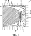
図5は、本発明に従った照明装置10の第二実施態様を示している。図1に示される第一実施態様と比べると、多孔性材料11がキャビティ12の内部に配置されている。
FIG. 5 shows a second embodiment of the
多孔性材料11は、ヒートパイプ流体10の循環を増大するために、繊維質構造を含む。ここでは、LED装置5を部分的に取り囲む多孔性媒体内に収容されるヒートパイプ流体5は、LED装置5内で生成される熱の故に気化される。上記に説明されたように、熱い蒸気は、筐体3及び/又はコリメータ2の壁で凝縮される。次に、凝縮された流体は、多孔性媒体11によって少なくとも部分的に吸収され、LED装置5に送り込まれる。従って、多孔性媒体11は、小さな繊維質構造を含むので、流体凝縮におけるグラジエントに由来する毛管力は、LED装置5への凝縮された流体の伝導をもたらす。
The
図6aは、コリメータ2の表面上に形成される層構造8の第一実施例の概略図を描写している。この層構造は、図1に示される実施態様において使用される。層構造は、コリメータ2の表面上に直接的に形成される反射塗膜14を含む。TIRコリメータ2の内表面への入射光の角度がLED装置5に近い地域内で高いという事実の故に、全反射特性を達成することは困難である。よって、反射塗膜14は、発光装置1の光学効率を増大する。よって、反射塗膜14上には、絶縁ラッカ16によって互いに対して並びに反射塗膜14から分離される2つの導電性層13が形成される。それに応じて、伝導層13をキャビティ12の内部及びヒートパイプ流体10に対して絶縁するために、最外側の伝導層13も絶縁ラッカ16によって被覆される。伝導層13は、LEDダイ5の電気端子を電線9に接続する。2つの積層伝導層13がここに示されているが、単一層内で互いから電気的に絶縁された2つの伝導性構造を形成することも可能であり得る。伝導層13及び反射層14は、真空蒸着プロセスで形成されるアルミニウムから成る。この実施態様ではアルミニウムが使用されているが、他の伝導性金属材料又は合金が、伝導層13の形成のために使用され得る。反射層14のための材料は、照明装置1の波長範囲に依存して選択され得る。ラッカ層16は、金属(或いは他の伝導性材料)蒸着に適合するよう使用される標準型のラッカから形成され得る。
FIG. 6 a depicts a schematic view of a first embodiment of the
図6bは、層構造8の他の実施例の概略図を示している。ここに示される実施例は、層構造8のより単純な構造を描写している。ここでは、単一の伝導層13がコリメータ2の表面上に形成されている。伝導層13は、アルミニウムから成り、上述のように、反射塗膜としても作用する。伝導層13は、層をキャビティ12の内部に対して絶縁するために、ラッカ16で被覆されている。ここでは、1つだけの伝導構造、即ち、伝導層13が層構造8内に存在しているので、LEDダイ6の1つだけの電気端子が、層構造8を介して電源に接続され得る。LEDダイ6の他の電気端子は、図5の実施態様中に例示的に示されるように、電線9を使用して、電源に直接的に接続され得る。代替的に、LEDダイ6の他の電気端子は、上記に説明されたように、ヒートパイプ流体10を使用して接続され得る。この場合には、ヒートパイプ流体10は、良好な電気伝導性をもたらさなければならない。LED層5及び筐体3は、ヒートパイプ流体10に接続するために、電気端子を提供しなければならない。
FIG. 6 b shows a schematic view of another embodiment of the
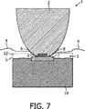
図7は、照明装置1の第三実施態様の概略的な側面図を示している。ここでは、コリメータ2は、筐体3内に部分的に取り付けられているので、LED装置5は、キャビティ12内に、故に、ヒートパイプ流体10と直接的に接触して配置される。それによって、コリメータ2の表面上のクラッディングが、有利に不必要である。何故ならば、ヒートパイプ流体10と接触するようになり得る表面の部分が、層構造8によって被覆されるからである。
FIG. 7 shows a schematic side view of a third embodiment of the lighting device 1. Here, since the
図8及び9は、照明装置1のさらなる実施態様を示している。図8に示される第四実施態様は、LED装置5に3つのLEDダイ6を示している。単一のコリメータ2’が、LEDダイス6の配列に適合されている。よって、より高いレベルの光束を達成することが可能である。図9に示される第五実施態様は、図8に示されるものと類似の構造を示している。図9は、共通のヒートスプレッダ7上の各LEDダイス6と共に、3つのコリメータ2を示している。本構成は、照明装置1の容易な適合性を可能にする。図示されていないが、用途に依存して、使用されるLEDの数を多く/少なくすることが容易に可能である。例えば、RGB色混合が必要とされるときには、多数の三色LEDが有利であり得る。
8 and 9 show a further embodiment of the lighting device 1. The fourth embodiment shown in FIG. 8 shows three LED dies 6 in the
ここに記載される実施態様は、限定的な意味よりも、むしろ例証的な意味であることが意図されている。請求項中の如何なる参照記号の使用も、各請求項の範囲を制限すべきではない。 The embodiments described herein are intended to be illustrative rather than limiting. The use of any reference signs in the claims should not limit the scope of each claim.
Claims (13)
筐体内に少なくとも部分的に取り付けられるコリメータと、
前記筐体内のキャビティ内に収容される非剛的な熱移転媒体とを含む、
照明装置であって、
前記LED装置は、無機接着剤若しくはガラスフリットを用いて、又は射出成形によって、前記コリメータにのみ剛的に結合され、前記LED装置によって生成される熱を放散するために、前記熱移転媒体内に少なくとも部分的に収容され、
前記コリメータは、透光性の固体材料であり、
前記熱移転媒体は、ゲル状又は液体である、
照明装置。An LED device;
A collimator mounted at least partially within the housing;
A non-rigid heat transfer medium housed in a cavity in the housing,
A lighting device,
The LED device is rigidly coupled only to the collimator using an inorganic adhesive or glass frit, or by injection molding, in the heat transfer medium to dissipate the heat generated by the LED device. At least partially contained ,
The collimator is a translucent solid material,
The heat transfer medium is gel or liquid,
Lighting device.
透光性の固体材料であるコリメータが、無機接着剤若しくはガラスフリットを用いて、又は、射出成形によって、LED装置に剛的に接続され、
前記コリメータが筐体内に少なくとも部分的に取り付けられ、
ゲル状又は液体である非剛的な熱移転媒体が、前記筐体内に設けられるキャビティ内に送り込まれ、
前記LED装置が前記熱移転媒体内に少なくとも部分的に収容される、
方法。A method of manufacturing a lighting device, comprising:
A collimator, which is a translucent solid material, is rigidly connected to the LED device using an inorganic adhesive or glass frit, or by injection molding,
The collimator is at least partially mounted within a housing;
A non-rigid heat transfer medium that is in the form of a gel or liquid is fed into a cavity provided in the housing;
The LED device is at least partially housed in the heat transfer medium;
Method.
Applications Claiming Priority (3)
| Application Number | Priority Date | Filing Date | Title |
|---|---|---|---|
| EP05112162 | 2005-12-14 | ||
| EP05112162.2 | 2005-12-14 | ||
| PCT/IB2006/054569 WO2007069119A1 (en) | 2005-12-14 | 2006-12-04 | Lighting device and method for manufacturing same |
Publications (2)
| Publication Number | Publication Date |
|---|---|
| JP2009519575A JP2009519575A (en) | 2009-05-14 |
| JP5097713B2 true JP5097713B2 (en) | 2012-12-12 |
Family
ID=37909666
Family Applications (1)
| Application Number | Title | Priority Date | Filing Date |
|---|---|---|---|
| JP2008545158A Active JP5097713B2 (en) | 2005-12-14 | 2006-12-04 | LIGHTING DEVICE AND LIGHTING DEVICE MANUFACTURING METHOD |
Country Status (7)
| Country | Link |
|---|---|
| US (1) | US8465183B2 (en) |
| EP (1) | EP1963741B1 (en) |
| JP (1) | JP5097713B2 (en) |
| KR (1) | KR101303370B1 (en) |
| CN (1) | CN101331358B (en) |
| TW (1) | TWI428537B (en) |
| WO (1) | WO2007069119A1 (en) |
Families Citing this family (32)
| Publication number | Priority date | Publication date | Assignee | Title |
|---|---|---|---|---|
| WO2007130359A2 (en) | 2006-05-02 | 2007-11-15 | Superbulbs, Inc. | Heat removal design for led bulbs |
| MX2008013870A (en) | 2006-05-02 | 2009-01-07 | Superbulbs Inc | Plastic led bulb. |
| US8193702B2 (en) | 2006-05-02 | 2012-06-05 | Switch Bulb Company, Inc. | Method of light dispersion and preferential scattering of certain wavelengths of light-emitting diodes and bulbs constructed therefrom |
| US20100219734A1 (en) * | 2007-06-08 | 2010-09-02 | Superbulbs, Inc. | Apparatus for cooling leds in a bulb |
| US8450927B2 (en) | 2007-09-14 | 2013-05-28 | Switch Bulb Company, Inc. | Phosphor-containing LED light bulb |
| US8439528B2 (en) | 2007-10-03 | 2013-05-14 | Switch Bulb Company, Inc. | Glass LED light bulbs |
| JP2011501464A (en) | 2007-10-24 | 2011-01-06 | テオス・インコーポレイテッド | Diffuser for LED light source |
| JP2011507152A (en) * | 2007-12-07 | 2011-03-03 | オスラム ゲゼルシャフト ミット ベシュレンクテル ハフツング | Heat sink and lighting device including heat sink |
| KR101372029B1 (en) * | 2008-02-10 | 2014-03-26 | 이형곤 | LED lighting device |
| EP2105659A1 (en) * | 2008-03-27 | 2009-09-30 | Wen-Long Chyn | LED lamp having higher efficiency |
| WO2010021676A1 (en) | 2008-08-18 | 2010-02-25 | Superbulbs, Inc. | Anti-reflective coatings for light bulbs |
| WO2010030332A1 (en) | 2008-09-11 | 2010-03-18 | Superbulbs, Inc. | End-of-life bulb circuitry |
| KR100898492B1 (en) * | 2008-09-12 | 2009-05-19 | 이동수 | A circualting and cooling type illuminator using a lihgt source of high illuminating power |
| US8192048B2 (en) * | 2009-04-22 | 2012-06-05 | 3M Innovative Properties Company | Lighting assemblies and systems |
| US8476812B2 (en) * | 2009-07-07 | 2013-07-02 | Cree, Inc. | Solid state lighting device with improved heatsink |
| CN102116424A (en) * | 2009-12-31 | 2011-07-06 | 鸿富锦精密工业(深圳)有限公司 | Light-emitting diode illuminating device |
| DE102010007687A1 (en) * | 2010-02-08 | 2011-08-11 | Siemens Aktiengesellschaft, 80333 | LED lamp with heat pipe as cooling |
| US8226274B2 (en) | 2011-03-01 | 2012-07-24 | Switch Bulb Company, Inc. | Liquid displacer in LED bulbs |
| US8759843B2 (en) | 2011-08-30 | 2014-06-24 | Abl Ip Holding Llc | Optical/electrical transducer using semiconductor nanowire wicking structure in a thermal conductivity and phase transition heat transfer mechanism |
| US8710526B2 (en) | 2011-08-30 | 2014-04-29 | Abl Ip Holding Llc | Thermal conductivity and phase transition heat transfer mechanism including optical element to be cooled by heat transfer of the mechanism |
| US8723205B2 (en) | 2011-08-30 | 2014-05-13 | Abl Ip Holding Llc | Phosphor incorporated in a thermal conductivity and phase transition heat transfer mechanism |
| US8591069B2 (en) | 2011-09-21 | 2013-11-26 | Switch Bulb Company, Inc. | LED light bulb with controlled color distribution using quantum dots |
| DE112011105763A5 (en) * | 2011-10-25 | 2014-09-25 | Osram Gmbh | Light-emitting component |
| CN102734745B (en) * | 2011-12-09 | 2013-07-31 | 安徽莱德光电技术有限公司 | LED (light-emitting diode) module |
| CN102927469B (en) * | 2012-10-31 | 2014-08-13 | 北京工业大学 | Heat-dissipating light-emitting diode (LED) lamp |
| WO2014069933A1 (en) * | 2012-11-05 | 2014-05-08 | (주)바이브 | Light-emitting diode lighting device with radiation, waterproof, and dampproof structure using fluid |
| KR101358873B1 (en) * | 2012-11-05 | 2014-02-11 | ㈜바이브 | Led light equipped with radiant heat and waterproof and moistureproof structure using liquid |
| US20140146543A1 (en) * | 2012-11-26 | 2014-05-29 | Magic Lighting Optics | Outdoor lighting device |
| ITMI20130787A1 (en) * | 2013-05-14 | 2014-11-15 | Tcore S R L | LIGHTING DEVICE |
| KR102217466B1 (en) * | 2013-12-02 | 2021-02-22 | 엘지이노텍 주식회사 | Lmap unit and lighting device and vehicle lamp using the same |
| DE102016113942A1 (en) | 2016-07-28 | 2018-02-15 | HELLA GmbH & Co. KGaA | Light source with a primary optic of silicone and method for producing the light source |
| DE102021130113A1 (en) * | 2021-11-18 | 2023-05-25 | OSRAM Opto Semiconductors Gesellschaft mit beschränkter Haftung | OPTOELECTRONIC COMPONENT AND OPTOELECTRONIC DEVICE |
Family Cites Families (26)
| Publication number | Priority date | Publication date | Assignee | Title |
|---|---|---|---|---|
| DE1225643B (en) | 1964-03-17 | 1966-09-29 | Dr Christoph Ruechardt | Process for the production of new organic peroxycarboxylic acid esters |
| JPS5960813A (en) * | 1982-09-29 | 1984-04-06 | 東芝ライテック株式会社 | Light illuminator |
| CA1230184A (en) | 1983-11-29 | 1987-12-08 | Toshiyuki Saito | Liquid cooling type high frequency solid state device |
| JPS60158649A (en) | 1984-01-30 | 1985-08-20 | Hitachi Ltd | Cooling device for electronic parts |
| US4847731A (en) * | 1988-07-05 | 1989-07-11 | The United States Of America As Represented By The Secretary Of The Navy | Liquid cooled high density packaging for high speed circuits |
| TW383508B (en) * | 1996-07-29 | 2000-03-01 | Nichia Kagaku Kogyo Kk | Light emitting device and display |
| JP2001517875A (en) | 1997-09-25 | 2001-10-09 | ユニバーシティ オブ ブリストル | Light irradiation device |
| JP2000106029A (en) * | 1998-09-30 | 2000-04-11 | Matsushita Electric Works Ltd | Illuminated stairs |
| US6547423B2 (en) | 2000-12-22 | 2003-04-15 | Koninklijke Phillips Electronics N.V. | LED collimation optics with improved performance and reduced size |
| EP1225643A1 (en) * | 2001-01-23 | 2002-07-24 | Interuniversitair Microelektronica Centrum Vzw | High efficiency unilateral light emitting device and method for fabricating such device |
| US6607286B2 (en) * | 2001-05-04 | 2003-08-19 | Lumileds Lighting, U.S., Llc | Lens and lens cap with sawtooth portion for light emitting diode |
| EP2241803B1 (en) * | 2001-05-26 | 2018-11-07 | GE Lighting Solutions, LLC | High power LED-lamp for spot illumination |
| DE10213042A1 (en) | 2002-03-23 | 2003-10-02 | Joachim Dohmann | Lamp used as a headlamp, brake light, rear light or indicator light in vehicles has a tightly sealed housing filled with a fluid so that the fluid permanently remains in the housing |
| CA2493130A1 (en) | 2002-07-25 | 2004-02-05 | Jonathan S. Dahm | Method and apparatus for using light emitting diodes for curing |
| AU2003298561A1 (en) | 2002-08-23 | 2004-05-13 | Jonathan S. Dahm | Method and apparatus for using light emitting diodes |
| US7313236B2 (en) * | 2003-04-09 | 2007-12-25 | International Business Machines Corporation | Methods and apparatus for secure and adaptive delivery of multimedia content |
| US6803607B1 (en) * | 2003-06-13 | 2004-10-12 | Cotco Holdings Limited | Surface mountable light emitting device |
| US7281807B2 (en) * | 2003-07-16 | 2007-10-16 | Honeywood Technologies, Llc | Positionable projection display devices |
| TWI225713B (en) * | 2003-09-26 | 2004-12-21 | Bin-Juine Huang | Illumination apparatus of light emitting diodes and method of heat dissipation thereof |
| US20050084229A1 (en) * | 2003-10-20 | 2005-04-21 | Victor Babbitt | Light insertion and dispersion system |
| JP2005150036A (en) * | 2003-11-19 | 2005-06-09 | Hiroshi Fujiyasu | Led lighting system and vehicle lamp |
| US7212344B2 (en) * | 2004-02-27 | 2007-05-01 | Philips Lumileds Lighting Company, Llc | Illumination system with aligned LEDs |
| DE102005013208A1 (en) * | 2004-03-21 | 2005-10-27 | Späth, Christian, Dipl.-Designer | Lighting unit has light emitting diodes mounted in housing tube filled with a cooling liquid |
| JP2005283708A (en) * | 2004-03-29 | 2005-10-13 | Sharp Corp | Lamp light source for image projecting device |
| JP2006073447A (en) * | 2004-09-06 | 2006-03-16 | Sony Corp | Cooling device for lamp and electronic equipment |
| US7843974B2 (en) * | 2005-06-30 | 2010-11-30 | Nokia Corporation | Audio and video synchronization |
-
2006
- 2006-12-04 WO PCT/IB2006/054569 patent/WO2007069119A1/en active Application Filing
- 2006-12-04 CN CN2006800470034A patent/CN101331358B/en active Active
- 2006-12-04 JP JP2008545158A patent/JP5097713B2/en active Active
- 2006-12-04 KR KR1020087016999A patent/KR101303370B1/en active IP Right Grant
- 2006-12-04 US US12/097,081 patent/US8465183B2/en active Active
- 2006-12-04 EP EP06832059.7A patent/EP1963741B1/en active Active
- 2006-12-11 TW TW095146302A patent/TWI428537B/en active
Also Published As
| Publication number | Publication date |
|---|---|
| KR20080081313A (en) | 2008-09-09 |
| CN101331358A (en) | 2008-12-24 |
| US20100265717A1 (en) | 2010-10-21 |
| CN101331358B (en) | 2013-06-12 |
| KR101303370B1 (en) | 2013-09-03 |
| EP1963741A1 (en) | 2008-09-03 |
| TW200745488A (en) | 2007-12-16 |
| JP2009519575A (en) | 2009-05-14 |
| TWI428537B (en) | 2014-03-01 |
| US8465183B2 (en) | 2013-06-18 |
| WO2007069119A1 (en) | 2007-06-21 |
| EP1963741B1 (en) | 2020-08-19 |
Similar Documents
| Publication | Publication Date | Title |
|---|---|---|
| JP5097713B2 (en) | LIGHTING DEVICE AND LIGHTING DEVICE MANUFACTURING METHOD | |
| US9234655B2 (en) | Lamp with remote LED light source and heat dissipating elements | |
| US8047686B2 (en) | Multiple light-emitting element heat pipe assembly | |
| RU2468289C2 (en) | Lighting module with similar directions of heat and light propagation | |
| US9068701B2 (en) | Lamp structure with remote LED light source | |
| EP2397753B1 (en) | Led lamp and a heat sink thereof having a wound heat pipe | |
| US7575354B2 (en) | Thermal management system for solid state automotive lighting | |
| JP5140711B2 (en) | LED package die with one small footprint | |
| US20090273924A1 (en) | High power LED lamp with heat dissipation enhancement | |
| US20100271836A1 (en) | Led lamp | |
| CN105402616A (en) | Light Assembly | |
| US20140265810A1 (en) | Solid-state light source using passive phase change cooling | |
| KR100646198B1 (en) | A Structure of LED Package for Dispersing Heat and LED Package with the Same | |
| US20110122630A1 (en) | Solid State Lamp Having Vapor Chamber | |
| US20050258440A1 (en) | Light emitting diode light source | |
| EP2893254A1 (en) | Lamp with remote led light source and heat dissipating elements | |
| RU2619912C2 (en) | Led lighting device |
Legal Events
| Date | Code | Title | Description |
|---|---|---|---|
| A621 | Written request for application examination |
Free format text: JAPANESE INTERMEDIATE CODE: A621 Effective date: 20091201 |
|
| RD03 | Notification of appointment of power of attorney |
Free format text: JAPANESE INTERMEDIATE CODE: A7423 Effective date: 20100329 |
|
| RD04 | Notification of resignation of power of attorney |
Free format text: JAPANESE INTERMEDIATE CODE: A7424 Effective date: 20100401 |
|
| RD04 | Notification of resignation of power of attorney |
Free format text: JAPANESE INTERMEDIATE CODE: A7424 Effective date: 20100405 |
|
| A131 | Notification of reasons for refusal |
Free format text: JAPANESE INTERMEDIATE CODE: A131 Effective date: 20111115 |
|
| A521 | Request for written amendment filed |
Free format text: JAPANESE INTERMEDIATE CODE: A523 Effective date: 20120214 |
|
| TRDD | Decision of grant or rejection written | ||
| A01 | Written decision to grant a patent or to grant a registration (utility model) |
Free format text: JAPANESE INTERMEDIATE CODE: A01 Effective date: 20120828 |
|
| A01 | Written decision to grant a patent or to grant a registration (utility model) |
Free format text: JAPANESE INTERMEDIATE CODE: A01 |
|
| A61 | First payment of annual fees (during grant procedure) |
Free format text: JAPANESE INTERMEDIATE CODE: A61 Effective date: 20120924 |
|
| R150 | Certificate of patent or registration of utility model |
Ref document number: 5097713 Country of ref document: JP Free format text: JAPANESE INTERMEDIATE CODE: R150 Free format text: JAPANESE INTERMEDIATE CODE: R150 |
|
| FPAY | Renewal fee payment (event date is renewal date of database) |
Free format text: PAYMENT UNTIL: 20150928 Year of fee payment: 3 |
|
| R250 | Receipt of annual fees |
Free format text: JAPANESE INTERMEDIATE CODE: R250 |
|
| S531 | Written request for registration of change of domicile |
Free format text: JAPANESE INTERMEDIATE CODE: R313531 |
|
| S533 | Written request for registration of change of name |
Free format text: JAPANESE INTERMEDIATE CODE: R313533 |
|
| R350 | Written notification of registration of transfer |
Free format text: JAPANESE INTERMEDIATE CODE: R350 |
|
| R250 | Receipt of annual fees |
Free format text: JAPANESE INTERMEDIATE CODE: R250 |
|
| S111 | Request for change of ownership or part of ownership |
Free format text: JAPANESE INTERMEDIATE CODE: R313113 |
|
| R350 | Written notification of registration of transfer |
Free format text: JAPANESE INTERMEDIATE CODE: R350 |
|
| R250 | Receipt of annual fees |
Free format text: JAPANESE INTERMEDIATE CODE: R250 |
|
| R250 | Receipt of annual fees |
Free format text: JAPANESE INTERMEDIATE CODE: R250 |
|
| R250 | Receipt of annual fees |
Free format text: JAPANESE INTERMEDIATE CODE: R250 |
|
| S531 | Written request for registration of change of domicile |
Free format text: JAPANESE INTERMEDIATE CODE: R313531 |
|
| S533 | Written request for registration of change of name |
Free format text: JAPANESE INTERMEDIATE CODE: R313533 |
|
| R350 | Written notification of registration of transfer |
Free format text: JAPANESE INTERMEDIATE CODE: R350 |
|
| R250 | Receipt of annual fees |
Free format text: JAPANESE INTERMEDIATE CODE: R250 |
|
| R250 | Receipt of annual fees |
Free format text: JAPANESE INTERMEDIATE CODE: R250 |