JP5093603B2 - Danger situation notification device - Google Patents
Danger situation notification device Download PDFInfo
- Publication number
- JP5093603B2 JP5093603B2 JP2008154565A JP2008154565A JP5093603B2 JP 5093603 B2 JP5093603 B2 JP 5093603B2 JP 2008154565 A JP2008154565 A JP 2008154565A JP 2008154565 A JP2008154565 A JP 2008154565A JP 5093603 B2 JP5093603 B2 JP 5093603B2
- Authority
- JP
- Japan
- Prior art keywords
- vibration
- interior member
- vehicle
- driver
- obstacle
- Prior art date
- Legal status (The legal status is an assumption and is not a legal conclusion. Google has not performed a legal analysis and makes no representation as to the accuracy of the status listed.)
- Expired - Fee Related
Links
Images


Description
本発明は、車両内装部材を強制振動させることで危険状況の存在を運転者に報知する危険状況報知装置に関する。 The present invention relates to a danger situation notification device that notifies a driver of the existence of a danger situation by forcibly vibrating a vehicle interior member.
従来、運転者用シートのシートクッションに右側振動体と左側振動体とを異なる部位に夫々設け、運転者用シートのシートバックの幅方向中央部に中央振動体を設け、これらの振動体の動作が障害物を検出する検出センサからの検出信号を受ける制御ユニットによって制御される車両用シート併用型報知システムが知られている(例えば、特許文献1参照)。このシステムでは、走行中に、自車両の後方に他の車両が演算で求めた警報距離よりも近くまで接近したときには中央振動体を駆動する。また、現在走行している走行レーンから右隣のレーンにレーン変更する際に、自車両の右側後方に他の車両が警報距離よりも近くまで接近したときには右側振動体を駆動し、現在走行している走行レーンから左隣のレーンにレーン変更する際に、自車両の左側後方に他の車両が警報距離よりも近くまで接近したときには左側振動体を駆動する。このような報知装置では、シートの特定箇所での振動を感知した場合、その特定箇所の振動を何らかの事象、例えば、「車両左側での障害物の検知」と結びつけるには、事前に特定箇所の振動と何らかの事象とを結びつけるための学習をしておく必要がある。また、運転者が思い込み運転や漫然運転を行っている際に、特定の同一箇所で振動が生じたとしても、多少の違和感を与えることはできても、車両の周囲を見渡そうといった積極的な危険意識を運転者に持たせるのは難しい。 Conventionally, the right vibration body and left vibration body are provided in different parts of the seat cushion of the driver's seat, respectively, and the central vibration body is provided at the center in the width direction of the seat back of the driver's seat. There is known a vehicle seat combined type notification system that is controlled by a control unit that receives a detection signal from a detection sensor that detects an obstacle (for example, see Patent Document 1). In this system, when traveling, the central vibrator is driven when another vehicle approaches the rear of the own vehicle closer than the alarm distance obtained by calculation. In addition, when changing the lane from the current driving lane to the right adjacent lane, if another vehicle approaches the right rear of the vehicle closer to the warning distance, the right vibrating body is driven and the vehicle is currently driving. When the lane is changed from the traveling lane to the left adjacent lane, the left vibrating body is driven when another vehicle approaches the left rear side of the host vehicle closer than the warning distance. In such a notification device, when vibration at a specific location of the seat is detected, in order to link the vibration at the specific location with an event such as "detection of an obstacle on the left side of the vehicle" It is necessary to learn to connect vibration and some kind of event. In addition, when a driver is driving in a speculative or random manner, even if vibration occurs at a specific location, it can give a sense of incongruity, but it is proactive to look around the vehicle. It is difficult to give the driver a sense of danger.
また、車両内装部材の強制振動による障害物報知ではないが、車両に搭載された複数のスピーカを用いて、障害物の位置する方向にその障害物の存在を通知する警告音などの音像を定位させる音響出力装置が知られている(例えば、特許文献2参照)。このような音像定位による報知装置においても、特定の同一箇所で定位された音を何らかの事象と関連づけるには、事前に音像定位と何らかの事象とを結びつけるための学習をしておく必要がある。また、このような装置でも、運転者が思い込み運転や漫然運転を行っている際に、車両の周囲を見渡そうといった積極的な危険意識を持たせるのは難しい。さらに、障害物の存在を通知する音声を報知することは、運転者がわずらわしいと感じてしまう可能性もある。 In addition, although it is not an obstacle notification due to forced vibration of vehicle interior members, a sound image such as a warning sound that notifies the presence of the obstacle in the direction of the obstacle is localized using a plurality of speakers mounted on the vehicle. An acoustic output device is known (see, for example, Patent Document 2). Even in such a sound image localization notification device, in order to associate a sound localized at a specific location with a certain event, it is necessary to learn in advance to associate the sound image localization with a certain event. In addition, even with such a device, it is difficult to give a positive danger awareness to look around the vehicle when the driver is driving in a speculative manner. Furthermore, there is a possibility that it is troublesome for the driver to notify the voice notifying the presence of the obstacle.
実際の車両走行中においては、車体自体が常に走路に応じて振動し、運転者と接触している部材も車体の振動が複雑に作用して常に振動している。よって、特定の同一箇所で振動を励起させても運転者に積極的な危険意識を持たせるのは難しい。
上述した実状に鑑み、本発明の目的は、危険な状況をすばやく確実に運転者に認識させ、運転者自身が危険回避行動をとるように誘導する危険状況報知装置を提供することである。
During actual traveling of the vehicle, the vehicle body itself constantly vibrates according to the road, and the member in contact with the driver always vibrates due to the complicated vibration of the vehicle body. Therefore, it is difficult to give the driver a positive awareness of danger even if vibration is excited at a specific same location.
In view of the above-described situation, an object of the present invention is to provide a dangerous situation notification device that promptly and reliably recognizes a dangerous situation and guides the driver to take a risk avoidance action.
上記目的を達成するため、本発明に係る危険状況報知装置の特徴構成は、車両周辺の危険状況を検出して危険状況検出情報を出力する危険状況検出手段と、前記車両の車室内において互いに間隔を有し、前記車両の運転者に接触しない一方の内装部材、及び、当該一方の内装部材に対して前記運転者に近く、且つ前記運転者に接触する他方の内装部材と、
前記一方の内装部材及び前記他方の内装部材に対して強制振動を同一の振動数となるよう付与する振動機構と、前記危険状況検出情報に基づいて前記内装部材における振動が前記一方の内装部材から前記他方の内装部材へ時間差をもって移行するように前記振動機構を制御する振動機構制御手段とを備えていることにある。
To achieve the above object, characteristic feature of the hazardous condition notifying device according to the present invention, a dangerous situation detecting means for outputting a dangerous situation detection information by detecting dangerous situations around the vehicle, and have contact to the passenger compartment of the vehicle One interior member that is spaced from each other and does not contact the driver of the vehicle, and the other interior member that is close to the driver and contacts the driver with respect to the one interior member;
A vibration mechanism for applying forced vibration to the one interior member and the other interior member to have the same frequency, and vibration in the interior member from the interior member based on the danger state detection information And a vibration mechanism control means for controlling the vibration mechanism so as to shift to the other interior member with a time difference .
この特徴構成によれば、危険状況検出情報に基づいて、車両内装部材における振動機構によって振動させられる箇所が、ある箇所(内装部材の一方)から他の箇所(内装部材の他方)に移行することになる。つまり、特定の1つの箇所が振動しているのではなく、その振動が移行するので、運転者はその事態を特異な現象として認識することになる。車両走行中において特定の内装部材が振動することはありうるが、その振動が移行するということは通常では起こりえない。人間にとってある現象が移行していくのを認識することは、その現象が不動であることに比べ、不安または危険意識を抱く傾向をもつ。従って、運転者が思い込み運転や漫然運転を行っていたとしても、不安感からその瞬間にブレーキを踏むなどの危険回避行動を行う可能性が高くなる。 According to this characteristic configuration, the location of the vehicle interior member that is vibrated by the vibration mechanism shifts from one location (one of the interior members) to another location (the other of the interior members) based on the danger situation detection information. become. In other words, since one specific place does not vibrate but vibrates, the driver recognizes the situation as a unique phenomenon. While a specific interior member may vibrate while the vehicle is traveling, it is not possible for the vibration to shift normally. Recognizing the transition of a phenomenon for human beings has a tendency to have anxiety or danger consciousness compared to immobility of the phenomenon. Therefore, even if the driver is driving in a belief or a random manner, there is a high possibility that the driver will perform a risk avoidance action such as stepping on the brake at that moment because of anxiety.
また、振動の移行が異なる2つの内装部材(内装部材の一方と内装部材の他方)が明確に異なる部材の場合、それらの異なる内装部材の間を振動が渡ることになるので、その振動の移行が通常では起こりえない特異なものとなり、一瞬にして運転者に強い危険意識を呼び起こすことになる。その結果、運転者が思い込み運転や漫然運転を行っていたとしても、ブレーキを踏むなどの危険回避行動を行う可能性がさらに高まる。 Further, when two interior members having different vibration transitions (one of the interior members and the other of the interior members) are members that are clearly different, vibrations pass between the different interior members. It becomes a peculiar thing that cannot occur normally, and instantly arouses a strong danger awareness to the driver. As a result, even if the driver performs a prejudice driving or a random driving, the possibility of performing a risk avoidance action such as stepping on a brake is further increased.
振動機構が内装部材の一方と内装部材の他方とに時間差をもって振動を付与する(開始する)。最初に内装部材の一方が振動し、所定時間後に内装部材の他方が振動することにより、簡単に振動が移行していく現象を作り出すことができる。本発明に係る危険状況報知装置の好適な特徴構成では、前記振動機構制御手段は、前記一方の内装部材における振動がフェードアウトしながら前記他方の内装部材における振動がフェードインするよう構成されていることである。これにより振動の移行がスムーズとなる。 Vibration mechanism applying vibration with a other of two hours difference while the interior member of the interior member (starts). When one of the interior members vibrates first and the other of the interior members vibrates after a predetermined time, it is possible to create a phenomenon in which vibration easily shifts. In a preferred characteristic configuration of the danger situation notification device according to the present invention, the vibration mechanism control means is configured such that the vibration in the other interior member fades in while the vibration in the one interior member fades out. It is. Thereby, the transition of vibration becomes smooth.
さらに内装部材の一方は内装部材の他方に比べて車両の運転者から離間している。このため、振動は、運転手から離れた箇所からより近い箇所に移行することになる。振動が運転者に向かって移行してくることで、何かが自身に接近するかのような感覚になり、運転者にさらに強い危険意識を呼び起こすことになる。 One of the inner instrumentation member further spaced from vehicles the driver than the other of the inner instrumentation member. For this reason , vibration shifts from a location away from the driver to a location closer. As the vibration shifts toward the driver, it feels as if something is approaching itself, and a stronger sense of danger is evoked by the driver.
また、運転者に近いほうである内装部材の他方を運転者と接触する内装部材、例えば運転者シートやステアリングハンドルとするならば、移行してきた振動を運転者は直接触感することになり、より強い振動の移行を認識することができる。 Further, interior member contacting the other of the instrumentation member is closer to the driver and OPERATION person, for example, if a driver's seat and steering wheel, would be touch directly the driver vibration has moved Can recognize stronger vibration transition.
振動機構によって内装部材の一方と内装部材の他方とに付与される振動の振動数が同一である。振動機構によって振動を付与される内装部材の固有振動数などの振動特性が類似していれば、移行前の振動と移行後の振動に相異感がなく、振動のスムーズな移行を実現できる。これに対して、移行前の振動の対象となる箇所または内装部材と移行後の振動の対象となる箇所または内装部材との固有振動数などの振動特性が大きく異なっている場合には、それぞれに同じ振動数を付与しても、結果として生じる振動はそれぞれ大きく異なることになる。従って、そのような場合には、前記箇所の一方と前記箇所の他方とに付与される振動の振動数を個別に選択し、結果として生じる振動がほぼ類似するような構成を採用するとよい。 Frequency of the vibration applied to the other one and the inner instrumentation member of the inner instrumentation member by vibration mechanism is the same. If the vibration characteristics such as natural frequency of the interior member that is applying vibration by vibration mechanism are similar, no differences feeling vibration after transition before migration vibration, can be achieved a smooth transition of the oscillation . On the other hand, if the vibration characteristics such as the natural frequency of the location or interior member subject to vibration before transition and the location or interior member subject to vibration after transition are significantly different, Even if the same frequency is applied, the resulting vibrations will vary greatly. Therefore, in such a case, it is preferable to individually select the frequency of vibration applied to one of the locations and the other of the locations and adopt a configuration in which the resulting vibrations are substantially similar.
以下本発明の実施形態を図面に基づいて説明する。この実施形態では、本発明に係る危険状況報知装置は車両に搭載され、車両の周辺の危険状況の一例としての障害物を検出し、検出された障害物と車両との間で起こりえる危険を運転者に認知させる障害物報知装置として構成されている。 Hereinafter, embodiments of the present invention will be described with reference to the drawings. In this embodiment, the dangerous situation notification device according to the present invention is mounted on a vehicle, detects an obstacle as an example of a dangerous situation around the vehicle, and detects a danger that may occur between the detected obstacle and the vehicle. It is configured as an obstacle notification device that is recognized by the driver.
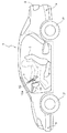
図1と図2に車両1の基本構成が示されている。運転席3の周辺には、回転操作力を前車輪2fに伝えて駆動操向を行うステアリングハンドル4、走行速度を制御するシフトレバー5やアクセルペダル6、前車輪2f及び後車輪2rに制動力を作用させるブレーキペダル7が配置されている。さらに、運転席3の近傍のフロントパネル10aにはモニタ11が備えられている。モニタ11の両側面にはスピーカ11aが備えられている。尚、スピーカ11aはドアの内側やその他の車両内装面に設けてもよい。モニタ11は、バックライトを備えた液晶式のものである。なお、モニタ11はナビゲーションシステムの表示装置としても用いられる。
1 and 2 show a basic configuration of the
車両1の後端には、車両後方周辺を撮影するカメラ8が備えられている。もちろん、さらに車両前方や車両側方を撮影するカメラを設けてもよい。バックカメラ8はCCD(charge coupled device)やCIS(CMOS image sensor)などの撮像素子を内蔵するとともに、撮影した情報をリアルタイムで動画情報として出力するデジタルカメラである。カメラ8は、例えば左右140度の視野を有する広角レンズを有し、例えば約30度の俯角を有して設置され、車両1の後方約8m程度までの領域を撮影することができる。
At the rear end of the
ステアリング4の操作系にはステアリングセンサ14が備えられ、ステアリング操作方向と操作量とが計測される。シフトレバー5の操作系にはシフト位置センサ15が備えられ、シフト位置が判別される。アクセルペダル6の操作系にはアクセルセンサ16が備えられ、操作量が計測される。ブレーキペダル7の操作系にはブレーキセンサ17が備えられ、操作の有無などが検出される。
A
また、この車両1の適当な箇所に、この実施形態では車両後面部と側面部と前面部とにそれぞれ2個の障害物センサ9が設けられている。障害物センサ9は、例えば、車両の周囲に存在する障害物を検出するミリ波レーダや画像認識装置等を利用して構成される。さらに、移動距離センサとして、前車輪2f及び後車輪2rの少なくとも一方の回転量を計測する回転センサ12が備えられている。
Further, in this embodiment, two
図2と図3とに示されているように、この実施形態では、内装部材の一例としてのフロントパネル10aにおけるステアリングハンドル4の前方に位置する箇所の裏面またはそれを支持しているフレームに第1振動アクチュエータ61が装着されている。さらに、内装部材の一例としてのステアリングハンドル4の左手グリップ箇所周辺と右手グリップ箇所周辺とに第2振動アクチュエータ62が装着されている。第1振動アクチュエータ61は圧電素子を振動源として構成することができる。また、エネルギーの大きな振動を必要とする場合には、ソレノイドによる往復運動される打撃部材による打撃を振動源とする構成や、電動モータの回転軸に設けられた偏芯打撃部材による打撃を振動源とする構成などを採用することができる。第2振動アクチュエータ62はスペースの関係から圧電素子を振動源として構成することが最適であり、さらに圧電素子として可撓性の高分子圧電シートを採用するのが好ましい。
As shown in FIG. 2 and FIG. 3, in this embodiment, the
20は、車両1における各種電子制御を行うECU(electronic control unit)を内蔵している電子制御ボックスである。本発明に特に関係するいくつかのECUの機能を模式的に示す機能ブロック図が図4に示されている。各ECUは、コンピュータを中核要素として構成されており、そのネットワーク機能を用いて相互のデータ伝送が可能となっている。図4には、ECUとして、車両状態検出ECU30と、ナビゲーションECU40と、危険状況報知ECU50とが示されている。
車両状態検出ECU30は、種々の車両状態に関する情報を生成する機能を有するが、本発明に特に関するものとして、障害物センサ9や各種センサ12、14〜17などの出力信号に基づいて車両周辺の危険状況を検出する危険状況検出手段31が備えられている。ただし、この実施形態では、危険状況検出手段31は、障害物センサ9などの出力信号に基づいて障害物までの距離と方向及び車両1との相対位置関係を演算して、衝突の可能性のある障害物を検出する障害物検出部31として構築されている。また、カメラ8からの撮影画像を画像処理して注意すべき対象や障害物の検出に利用することも可能である。障害物検出部31で生成された危険状況検出情報(この実施形態では以後障害物検出情報と称する)は、危険状況報知ECU50や、ここでは図示されていない乗員保護ECUなどに送られる。
The vehicle
ナビゲーションECU40は、この車両1に装備されているカーナビゲーションシステムの制御ユニットである。ナビゲーションECU40は、その入力系として地図情報を与える地図データベース41と、自車位置情報を与えるGPSユニット42とが接続されており、入力系としてモニタ11とスピーカ11aが接続されている。なお、ここでは図示されていないが、より正確な自車位置を取得するため、ナビゲーションECU40には、ジャイロセンサなどの方位センサからの方位情報や距離センサ(回転センサ12で兼用することができる)からの走行距離情報も与えられる。
The
危険状況報知ECU50は、図4に示すように、振動機構制御手段51と、オーディオ制御手段52とを備えている。振動機構制御手段51は、上述した第1振動アクチュエータ61と第2振動アクチュエータ62とをそれぞれ振動ドライバ69を介して個別に制御することができる。ここでは、第1振動アクチュエータ61と第2振動アクチュエータ62とそれぞれの振動ドライバ69とによって車両内装部材の所定箇所に振動を生じさせる振動機構60が構成されている。この実施形態では、振動機構制御手段51は、車両状態検出ECU30の障害物検出部31から送られてきた障害物検出情報に基づいて、第1振動アクチュエータ61が装着されたフロントパネル10aの所定箇所を第1振動アクチュエータ61によって振動させ、さらに第2振動アクチュエータ62が装着されたステアリングハンドル4の所定箇所を第2振動アクチュエータ62によって振動させることで、フロントパネル10aからステアリングハンドル4に振動が移行しているように運転者に感じさせる。このような振動の移行は、障害物検出部31によって検出された障害物と車両1との間で起こりうる危険を運転者に感じ取らせることに寄与する。
As shown in FIG. 4, the dangerous
オーディオ制御手段52は、オーディオドライバ53を介して事前に設定されている所定の音をスピーカ11から鳴らすことができる。従って、このオーディオ制御手段52は、振動機構60によるフロントパネル10aの所定箇所とステアリングハンドル4の所定箇所とにおける振動発生時に、その振動をより運転者に感じ取らせるために、スピーカ11bから振動効果音を鳴らすことも可能である。
The audio control means 52 can play a predetermined sound set in advance via the
次に、図5に示されたタイムチャート図を用いて、振動機構制御手段51における振動機構60に対する動作制御をより詳しく説明する。
振動機構制御手段51が、障害物検出部31から送られてきた障害物検出情報を評価して、障害物検出部31によって検出された障害物が車両1との間で危険を生じさせると判定した場合、第1振動トリガーを生成し、振動ドライバ69を介して、前もって設定された持続時間:Tを有する振動を第1振動アクチュエータ61に発生させる。さらに、第1振動トリガーの生成から、時間差:TTをもって第2振動トリガーを生成し、振動ドライバ69を介して、前もって設定された持続時間:Tを有する振動を第2振動アクチュエータ62に発生させる。この例では、第1振動アクチュエータ61による振動から第2振動アクチュエータ6よる振動への移行をフェードアウト・フェードインで行う。このため、第2振動トリガーのタイミングで、第1振動アクチュエータ61の振動ドライバ69に対して、(T−TT)の時間長さを有するフェードアウト信号を与えることで、第1振動アクチュエータ61による振動をフェードアウトする。同様に、第1振動トリガーのタイミングで、第2振動アクチュエータ62の振動ドライバ69に対して、(T−TT)の時間長さを有するフェードイン信号を与えることで、第2振動アクチュエータ62による振動をフェードインする。これにより、フロントパネル10aからステアリングハンドル4への振動の移行がスムーズに行われる。第1振動アクチュエータ61による振動と2振動アクチュエータ62による振動との振動数は同一でよいが、フロントパネル10aとステアリングハンドル4とで運転者が感じる振動が感覚的に類似するように、それぞれの振動数を事前に設定しておいてもよい。また、第1振動アクチュエータ61による振動と第2振動アクチュエータ6よる振動を1回限りではなく、所定繰り返し時間でもって、複数回繰り返して、振動の移行を繰り返してもよい。なお、第1振動アクチュエータ61による振動から第2振動アクチュエータ6よる振動への移行においてフェードアウト・フェードインを行わない場合、上記持続時間:Tと上記時間差:TTを同一にすると、振動移行に途切れがなくなる。
Next, the operation control for the
The vibration mechanism control means 51 evaluates the obstacle detection information sent from the
なお、本発明による危険状況報知装置は、思い込み運転や漫然運転を行っている運転者に危険が起こるかもしれないと認識させることを意図しているので、振動機構60によって作り出される移行する振動の周波数(振動数)は、心理的に怖れないしは不安を呼び起こしやすいといわれている低周波が適している。 Note that the danger situation notification device according to the present invention is intended to make a driver who performs speculative driving or random driving recognize that a danger may occur. As the frequency (frequency), a low frequency that is said to be psychologically scary or likely to cause anxiety is suitable.
〔その他の実施形態〕
(1)
上述した実施形態では、移行していく振動を作り出すため第1振動アクチュエータ61と第2振動アクチュエータ62の2つの振動アクチュエータだけが用いられていたが、もちろん3個以上の振動アクチュエータを用いることも可能である。この場合、振動の移行がより精度よく行われるという利点が得られる。
(2)
図6は、振動機構60の別な実施形態における図2に対応する運転席前方の説明図である。この実施形態では、先の実施形態に比べて、ステアリングハンドル4に装着されていた第2振動アクチュエータ62に代えて、フロントパネル10aの運転席3から第1振動アクチュエータ61より離れたフロントパネル10aの左側内装部材に第3振動アクチュエータ63が装着されていることで異なっている。つまり、この実施形態では、フロントパネル10aの左側内装部材と右側内装部材とが振動機構60によって加振される構成となっている。従って、障害物検出情報に基づいて運転者に起こりうる危険を認識させる場合には、まず、第3振動アクチュエータ63によりフロントパネル10aの左側内装部材(運転者の左前方)を振動させ、次いで第1振動アクチュエータ61によりフロントパネル10aの右側内装部材(運転者の正面前方)を振動させることで、振動の移行を運転者の視野内で行っている。
(3)
図7は、振動機構60のさらに別な実施形態における図1に対応する、車両の一部を切り欠いて運転席を見た斜視図である。この実施形態では、まず、ステアリングハンドル4の左手グリップ箇所周辺と右手グリップ箇所周辺とに第2振動アクチュエータ62が装着されている。この第2振動アクチュエータ62を中心として、正面前方に第1振動アクチュエータ61、左前方に第3振動アクチュエータ63、左側方に第4振動アクチュエータ64、右側方に第5アクチュエータ65、左後方に第6アクチュエータ66、右後方に第7振動アクチュエータ67が配置されている。第1振動アクチュエータ61と第3振動アクチュエータ63とはフロントパネル10aに装着されている。第4振動アクチュエータ64は内装部材としての左ドアパネル10bに装着され、第5アクチュエータ65は内装部材としての右ドアパネル10cに装着されている。第6振動アクチュエータ66と第7振動アクチュエータ67とは内装部材としてのバックパネル10dに装着されている。またこの実施形態では、障害物検出情報には検出された障害物の運転席3からの方向が含まれている。従って、振動機構制御手段51は、検出された障害物の方向に対応させて、振動が運転者(実際はステアリングハンドル4)に移行するように振動機構60を振動させる。例えば、左側方に障害物が検出された場合には、まず、第4振動アクチュエータ64により左ドアパネル10bを振動させ、次いで第2振動アクチュエータ62によりステアリングハンドル4を振動させることで、振動の移行方向と障害物の検出方向を対応させている。これにより、運転者は車両1の左方周辺領域に注意を払うことになる。
(4)
本発明は、上述した種々の実施形態で特定されていた振動アクチュエータの装着箇所に限定しているわけではない。本発明の枠内で各種車両内装部材の任意の箇所に振動アクチュエータを装着し、当該箇所を振動させてもよい。
(5)
上述した実施形態では、障害物となる物体を検知することに本発明が適用されていたが、本発明はこれに限定するものではない。例えば、画像認識などにより信号機や道路標識を検知し、これを運転者に速やかに認知させることで、信号機や道路標識の見過ごしを回避する目的にも適用可能である。また、ナビゲーションECU40と車両状態検出ECU30との連携で、車両が正規の道路から逸脱する可能性があることが検出された場合に、これを回避するために本発明の危険状況報知装置を適用することも可能である。
[Other Embodiments]
(1)
In the above-described embodiment, only two vibration actuators, the
(2)
FIG. 6 is an explanatory diagram of the front of the driver's seat corresponding to FIG. 2 in another embodiment of the
(3)
FIG. 7 is a perspective view corresponding to FIG. 1 in still another embodiment of the
(4)
The present invention is not limited to the mounting position of the vibration actuator specified in the various embodiments described above. Within the frame of the present invention, a vibration actuator may be attached to any location of various vehicle interior members, and the location may be vibrated.
(5)
In the above-described embodiment, the present invention is applied to detecting an object that becomes an obstacle, but the present invention is not limited to this. For example, the present invention can be applied to the purpose of avoiding oversight of traffic lights and road signs by detecting traffic lights and road signs through image recognition and prompting the driver to recognize them. In addition, when the
4 ステアリングハンドル(内装部材の一例)
9 障害物センサ
10aフロントパネル(内装部材の一例)
11bスピーカ
30 車両状態検出ECU
31 危険状況検出手段(障害物検出部)
40 ナビゲーションECU
50 危険状況報知ECU
51 振動機構制御手段
52 オーディオ制御手段
60 振動機構
61 第1振動アクチュエータ
62 第2振動アクチュエータ
63 第3振動アクチュエータ
69 振動ドライバ
4 Steering handle (an example of an interior member)
9
31 Danger status detection means (obstacle detection unit)
40 Navigation ECU
50 Danger status notification ECU
51 vibration mechanism control means 52 audio control means 60
Claims (4)
前記車両の車室内において互いに間隔を有し、前記車両の運転者に接触しない一方の内装部材、及び、当該一方の内装部材に対して前記運転者に近く、且つ前記運転者に接触する他方の内装部材と、
前記一方の内装部材及び前記他方の内装部材に対して強制振動を同一の振動数となるよう付与する振動機構と、
前記危険状況検出情報に基づいて前記内装部材における振動が前記一方の内装部材から前記他方の内装部材へ時間差をもって移行するように前記振動機構を制御する振動機構制御手段とを備えた危険状況報知装置。 A dangerous situation detection means for detecting a dangerous situation around the vehicle and outputting dangerous situation detection information;
Having a distance from one another and have contact to the passenger compartment of the vehicle, one of the interior member not in contact with the driver of the vehicle, and, close to the driver to one of the interior member such, and in contact with the driver The other interior member;
A vibration mechanism that applies forced vibration to the one interior member and the other interior member to have the same frequency ;
Hazardous condition notifying device provided with a vibrating mechanism control means for controlling the oscillation mechanism so that the vibration in the interior member is shifted with a time difference from the one of the interior member to the other interior member on the basis of the hazardous situation detected information .
Priority Applications (1)
| Application Number | Priority Date | Filing Date | Title |
|---|---|---|---|
| JP2008154565A JP5093603B2 (en) | 2008-06-12 | 2008-06-12 | Danger situation notification device |
Applications Claiming Priority (1)
| Application Number | Priority Date | Filing Date | Title |
|---|---|---|---|
| JP2008154565A JP5093603B2 (en) | 2008-06-12 | 2008-06-12 | Danger situation notification device |
Publications (2)
| Publication Number | Publication Date |
|---|---|
| JP2009298281A JP2009298281A (en) | 2009-12-24 |
| JP5093603B2 true JP5093603B2 (en) | 2012-12-12 |
Family
ID=41545639
Family Applications (1)
| Application Number | Title | Priority Date | Filing Date |
|---|---|---|---|
| JP2008154565A Expired - Fee Related JP5093603B2 (en) | 2008-06-12 | 2008-06-12 | Danger situation notification device |
Country Status (1)
| Country | Link |
|---|---|
| JP (1) | JP5093603B2 (en) |
Families Citing this family (2)
| Publication number | Priority date | Publication date | Assignee | Title |
|---|---|---|---|---|
| JP6591879B2 (en) | 2015-11-30 | 2019-10-16 | クラリオン株式会社 | Vehicle notification device and vehicle notification method |
| WO2019044826A1 (en) * | 2017-08-31 | 2019-03-07 | パイオニア株式会社 | Vibration control device |
Family Cites Families (2)
| Publication number | Priority date | Publication date | Assignee | Title |
|---|---|---|---|---|
| JP2001199296A (en) * | 2000-01-17 | 2001-07-24 | Matsushita Electric Ind Co Ltd | Warning device, driver's seat having vibrating body, and mobile body equipped with warning device on vehicle |
| JP4530052B2 (en) * | 2008-01-18 | 2010-08-25 | 日産自動車株式会社 | VEHICLE DRIVE OPERATION ASSISTANCE DEVICE AND VEHICLE HAVING VEHICLE DRIVE OPERATION ASSISTANCE DEVICE |
-
2008
- 2008-06-12 JP JP2008154565A patent/JP5093603B2/en not_active Expired - Fee Related
Also Published As
| Publication number | Publication date |
|---|---|
| JP2009298281A (en) | 2009-12-24 |
Similar Documents
| Publication | Publication Date | Title |
|---|---|---|
| JP4139929B2 (en) | Vehicle seat device and vehicle seat combined type notification system | |
| JP6123873B2 (en) | Advanced driver support system for vehicle and control method thereof | |
| JP6519435B2 (en) | Notification management apparatus and notification management method | |
| JP6342856B2 (en) | Vehicle control device | |
| US8063754B2 (en) | Vehicle state information transmission apparatus using tactile device | |
| JP5003734B2 (en) | Information presentation device | |
| JP2010073134A (en) | Vehicle surrounding recognition support system | |
| WO2013129184A1 (en) | Travel control device and travel control method | |
| JP2006264624A (en) | Lane maintaining assistant device | |
| JP2005088717A (en) | Alarm device for automobile | |
| JP2006199094A (en) | Information presenting device for vehicle | |
| EP3495187B1 (en) | Attention attracting device for vehicle | |
| CN110582436B (en) | Steering assist system and method | |
| EP1939061B1 (en) | A tactile signaling arrangement for warning the driver of a vehicle, as well as a vehicle steering device and driving assistance system including such an arrangement | |
| KR20140036367A (en) | Method and apparatus for automobile driving guidance and hazard alert using vibration | |
| JP2000168468A (en) | Information transmitting device for vehicle | |
| JP5093603B2 (en) | Danger situation notification device | |
| JP2005130613A (en) | Vehicle | |
| JP4852801B2 (en) | Driving support device | |
| JP2008006920A (en) | Driving operation assist device for vehicle and vehicle equipped with the same | |
| JP2008158671A (en) | Vehicle collision warning apparatus | |
| JP6943702B2 (en) | Switch device | |
| JP3736003B2 (en) | Vehicle alarm device | |
| JP7120915B2 (en) | vehicle control system | |
| JP7478052B2 (en) | Vehicle driving support device |
Legal Events
| Date | Code | Title | Description |
|---|---|---|---|
| A621 | Written request for application examination |
Free format text: JAPANESE INTERMEDIATE CODE: A621 Effective date: 20110523 |
|
| A131 | Notification of reasons for refusal |
Free format text: JAPANESE INTERMEDIATE CODE: A131 Effective date: 20120621 |
|
| A977 | Report on retrieval |
Free format text: JAPANESE INTERMEDIATE CODE: A971007 Effective date: 20120621 |
|
| A521 | Written amendment |
Free format text: JAPANESE INTERMEDIATE CODE: A523 Effective date: 20120727 |
|
| TRDD | Decision of grant or rejection written | ||
| A01 | Written decision to grant a patent or to grant a registration (utility model) |
Free format text: JAPANESE INTERMEDIATE CODE: A01 Effective date: 20120823 |
|
| A01 | Written decision to grant a patent or to grant a registration (utility model) |
Free format text: JAPANESE INTERMEDIATE CODE: A01 |
|
| A61 | First payment of annual fees (during grant procedure) |
Free format text: JAPANESE INTERMEDIATE CODE: A61 Effective date: 20120905 |
|
| FPAY | Renewal fee payment (event date is renewal date of database) |
Free format text: PAYMENT UNTIL: 20150928 Year of fee payment: 3 |
|
| LAPS | Cancellation because of no payment of annual fees |