JP5089579B2 - Laryngeal mask airway device - Google Patents
Laryngeal mask airway device Download PDFInfo
- Publication number
- JP5089579B2 JP5089579B2 JP2008512916A JP2008512916A JP5089579B2 JP 5089579 B2 JP5089579 B2 JP 5089579B2 JP 2008512916 A JP2008512916 A JP 2008512916A JP 2008512916 A JP2008512916 A JP 2008512916A JP 5089579 B2 JP5089579 B2 JP 5089579B2
- Authority
- JP
- Japan
- Prior art keywords
- support
- airway
- tube
- patient
- mask
- Prior art date
- Legal status (The legal status is an assumption and is not a legal conclusion. Google has not performed a legal analysis and makes no representation as to the accuracy of the status listed.)
- Active
Links
Images


Classifications
-
- A—HUMAN NECESSITIES
- A61—MEDICAL OR VETERINARY SCIENCE; HYGIENE
- A61M—DEVICES FOR INTRODUCING MEDIA INTO, OR ONTO, THE BODY; DEVICES FOR TRANSDUCING BODY MEDIA OR FOR TAKING MEDIA FROM THE BODY; DEVICES FOR PRODUCING OR ENDING SLEEP OR STUPOR
- A61M16/00—Devices for influencing the respiratory system of patients by gas treatment, e.g. mouth-to-mouth respiration; Tracheal tubes
- A61M16/04—Tracheal tubes
- A61M16/0434—Cuffs
- A61M16/045—Cuffs with cuffs partially or completely inflated by the respiratory gas
-
- A—HUMAN NECESSITIES
- A61—MEDICAL OR VETERINARY SCIENCE; HYGIENE
- A61M—DEVICES FOR INTRODUCING MEDIA INTO, OR ONTO, THE BODY; DEVICES FOR TRANSDUCING BODY MEDIA OR FOR TAKING MEDIA FROM THE BODY; DEVICES FOR PRODUCING OR ENDING SLEEP OR STUPOR
- A61M16/00—Devices for influencing the respiratory system of patients by gas treatment, e.g. mouth-to-mouth respiration; Tracheal tubes
- A61M16/04—Tracheal tubes
- A61M16/0402—Special features for tracheal tubes not otherwise provided for
- A61M16/0409—Special features for tracheal tubes not otherwise provided for with mean for closing the oesophagus
-
- A—HUMAN NECESSITIES
- A61—MEDICAL OR VETERINARY SCIENCE; HYGIENE
- A61M—DEVICES FOR INTRODUCING MEDIA INTO, OR ONTO, THE BODY; DEVICES FOR TRANSDUCING BODY MEDIA OR FOR TAKING MEDIA FROM THE BODY; DEVICES FOR PRODUCING OR ENDING SLEEP OR STUPOR
- A61M16/00—Devices for influencing the respiratory system of patients by gas treatment, e.g. mouth-to-mouth respiration; Tracheal tubes
- A61M16/04—Tracheal tubes
- A61M16/0402—Special features for tracheal tubes not otherwise provided for
- A61M16/0415—Special features for tracheal tubes not otherwise provided for with access means to the stomach
-
- A—HUMAN NECESSITIES
- A61—MEDICAL OR VETERINARY SCIENCE; HYGIENE
- A61M—DEVICES FOR INTRODUCING MEDIA INTO, OR ONTO, THE BODY; DEVICES FOR TRANSDUCING BODY MEDIA OR FOR TAKING MEDIA FROM THE BODY; DEVICES FOR PRODUCING OR ENDING SLEEP OR STUPOR
- A61M16/00—Devices for influencing the respiratory system of patients by gas treatment, e.g. mouth-to-mouth respiration; Tracheal tubes
- A61M16/04—Tracheal tubes
- A61M16/0434—Cuffs
- A61M16/0443—Special cuff-wall materials
-
- A—HUMAN NECESSITIES
- A61—MEDICAL OR VETERINARY SCIENCE; HYGIENE
- A61M—DEVICES FOR INTRODUCING MEDIA INTO, OR ONTO, THE BODY; DEVICES FOR TRANSDUCING BODY MEDIA OR FOR TAKING MEDIA FROM THE BODY; DEVICES FOR PRODUCING OR ENDING SLEEP OR STUPOR
- A61M16/00—Devices for influencing the respiratory system of patients by gas treatment, e.g. mouth-to-mouth respiration; Tracheal tubes
- A61M16/04—Tracheal tubes
- A61M16/0434—Cuffs
- A61M16/0445—Special cuff forms, e.g. undulated
- A61M16/0447—Bell, canopy or umbrella shaped
-
- A—HUMAN NECESSITIES
- A61—MEDICAL OR VETERINARY SCIENCE; HYGIENE
- A61M—DEVICES FOR INTRODUCING MEDIA INTO, OR ONTO, THE BODY; DEVICES FOR TRANSDUCING BODY MEDIA OR FOR TAKING MEDIA FROM THE BODY; DEVICES FOR PRODUCING OR ENDING SLEEP OR STUPOR
- A61M16/00—Devices for influencing the respiratory system of patients by gas treatment, e.g. mouth-to-mouth respiration; Tracheal tubes
- A61M16/04—Tracheal tubes
- A61M16/0463—Tracheal tubes combined with suction tubes, catheters or the like; Outside connections
-
- A—HUMAN NECESSITIES
- A61—MEDICAL OR VETERINARY SCIENCE; HYGIENE
- A61M—DEVICES FOR INTRODUCING MEDIA INTO, OR ONTO, THE BODY; DEVICES FOR TRANSDUCING BODY MEDIA OR FOR TAKING MEDIA FROM THE BODY; DEVICES FOR PRODUCING OR ENDING SLEEP OR STUPOR
- A61M16/00—Devices for influencing the respiratory system of patients by gas treatment, e.g. mouth-to-mouth respiration; Tracheal tubes
- A61M16/08—Bellows; Connecting tubes ; Water traps; Patient circuits
- A61M16/0816—Joints or connectors
-
- A—HUMAN NECESSITIES
- A61—MEDICAL OR VETERINARY SCIENCE; HYGIENE
- A61M—DEVICES FOR INTRODUCING MEDIA INTO, OR ONTO, THE BODY; DEVICES FOR TRANSDUCING BODY MEDIA OR FOR TAKING MEDIA FROM THE BODY; DEVICES FOR PRODUCING OR ENDING SLEEP OR STUPOR
- A61M16/00—Devices for influencing the respiratory system of patients by gas treatment, e.g. mouth-to-mouth respiration; Tracheal tubes
- A61M16/08—Bellows; Connecting tubes ; Water traps; Patient circuits
- A61M16/0875—Connecting tubes
-
- A—HUMAN NECESSITIES
- A61—MEDICAL OR VETERINARY SCIENCE; HYGIENE
- A61M—DEVICES FOR INTRODUCING MEDIA INTO, OR ONTO, THE BODY; DEVICES FOR TRANSDUCING BODY MEDIA OR FOR TAKING MEDIA FROM THE BODY; DEVICES FOR PRODUCING OR ENDING SLEEP OR STUPOR
- A61M16/00—Devices for influencing the respiratory system of patients by gas treatment, e.g. mouth-to-mouth respiration; Tracheal tubes
- A61M16/04—Tracheal tubes
- A61M16/0488—Mouthpieces; Means for guiding, securing or introducing the tubes
- A61M16/049—Mouthpieces
- A61M16/0493—Mouthpieces with means for protecting the tube from damage caused by the patient's teeth, e.g. bite block
Description
本発明は、喉頭マスク気道装置に関する。 The present invention relates to a laryngeal mask airway device.
喉頭マスク気道装置は、意識不明の患者に気道を確立するのに有用な周知の装置である。米国特許第4,509,514号は、喉頭マスク気道装置を説明する多くの公報の1つである。そのような装置は、長年の間使用されてきており、より古いよりよく知られてさえいる気管内チューブに対する代案を提供する。少なくとも70年の間、チューブの遠位端に配置された膨張可能なバルーンを備えた長く細いチューブを具備する気管内チューブが、意識不明の患者に気道を確立するために使用されてきている。操作において、気管内チューブの遠位端は、患者の口を通って挿入され、患者の気管を過ぎる。ひとたびそのように位置決めされると、バルーンは、気管の内側裏層で封止を形成するように膨張する。この封止が確立した後に、正の圧力がチューブの近位端に加えられ、患者の肺を通気してもよい。また、バルーンと気管の内側裏層との間の封止が、肺を吸引から保護する(たとえば、封止は、胃から逆流した物質が患者の肺内に吸引されるのを防止する)。 A laryngeal mask airway device is a well-known device useful for establishing an airway in an unconscious patient. U.S. Pat. No. 4,509,514 is one of many publications describing laryngeal mask airway devices. Such devices have been used for many years and provide an alternative to the older, better known even endotracheal tube. For at least 70 years, endotracheal tubes with long, narrow tubes with inflatable balloons located at the distal end of the tubes have been used to establish airways in unconscious patients. In operation, the distal end of the endotracheal tube is inserted through the patient's mouth and past the patient's trachea. Once so positioned, the balloon is inflated to form a seal with the inner lining of the trachea. After this seal is established, positive pressure may be applied to the proximal end of the tube to vent the patient's lungs. Also, a seal between the balloon and the inner lining of the trachea protects the lung from aspiration (eg, the seal prevents backflowed material from the stomach from being aspirated into the patient's lungs).
気管内チューブは、非常に成功しているが、数種類の主な不利点がある。気管内チューブの第1の不利点は、チューブを適切に挿入することの困難さに関係する。気管内チューブを患者内に挿入することは、高度のスキルを必要とする手順である。また、熟練した医者でさえ、気管内チューブの挿入は、困難であるかまたは可能でないこともある。多くの場合、気管内チューブを挿入することの困難さは、悲劇的なことに患者の死を招くが、それは、十分速く患者に気道を確立することができなかったからである。また、気管内チューブを挿入することは、通常、患者の頭部および頚部を動かすことを必要とし、さらに、患者の顎を強制的に広く開くことを必要とする。これらの必要な操作は、頸部損傷を受けているかもしれない患者内に、気管内チューブを挿入することを困難にするかまたは望ましくないものにする。 Endotracheal tubes are very successful but have several major disadvantages. The first disadvantage of the endotracheal tube is related to the difficulty of properly inserting the tube. Inserting an endotracheal tube into a patient is a procedure that requires a high degree of skill. Also, even an experienced physician may find it difficult or impossible to insert an endotracheal tube. In many cases, the difficulty of inserting an endotracheal tube tragically results in patient death, because the airway could not be established in the patient fast enough. Also, inserting an endotracheal tube usually requires moving the patient's head and neck, and also forcing the patient's jaw to open widely. These necessary manipulations make it difficult or undesirable to insert an endotracheal tube into a patient who may have suffered neck injury.
気管内チューブとは対照的に、喉頭マスク気道装置を患者内に挿入し、それによって気道を確立することは、比較的容易である。また、喉頭マスク気道装置は、不適当に挿入された場合でさえ依然として気道を確立する傾向があるという点で、「寛大な」装置である。それに応じて、喉頭マスク気道装置は、「救命」装置と考えられることが多い。また、喉頭マスク気道装置は、患者の頭部、頚部および顎を比較的小さく動かすだけで挿入されてもよい。さらに、喉頭マスク気道装置は、気管の敏感な内側裏層に接触する必要なく患者の肺への通気を提供し、確立された気道のサイズは典型的に、気管内チューブで確立された気道のサイズよりもかなり大きい。また、喉頭マスク気道装置は、気管内チューブと同一程度に咳に干渉しない。主にこれらの利点のため、喉頭マスク気道装置は、近年では、ますます人気を博している。 In contrast to the endotracheal tube, it is relatively easy to insert the laryngeal mask airway device into the patient and thereby establish the airway. Also, the laryngeal mask airway device is a “generous” device in that it tends to still establish the airway even if inserted improperly. Accordingly, laryngeal mask airway devices are often considered “lifesaving” devices. Also, the laryngeal mask airway device may be inserted with only a relatively small movement of the patient's head, neck and jaw. In addition, the laryngeal mask airway device provides ventilation to the patient's lungs without the need to contact the sensitive inner lining of the trachea, and the established airway size is typically that of the airway established with the endotracheal tube. Much larger than size. Also, the laryngeal mask airway device does not interfere with cough as much as the endotracheal tube. Mainly because of these benefits, laryngeal mask airway devices have become increasingly popular in recent years.
米国特許第5,303,697号および第6,079,409号には、「挿管喉頭マスク気道装置」と称されてもよい先行技術の装置の例が記載されている。
挿管装置は、気管内チューブの挿入を容易にするのに有用であるという追加利点を有する。挿管喉頭マスク気道装置が患者に位置した後に、装置は、その後に挿入される気管内チューブ用のガイドとして作用することができる。このように喉頭マスク気道装置を使用することは、一般に気管内チューブの「ブラインド挿入」として知られていることを容易にする。挿管喉頭マスク気道装置を挿入するために必要なのは、患者の頭部、頚部および顎をわずかに動かすことだけであり、ひとたび装置が患者に位置すると、気管内チューブは、実質的に患者をさらに動かすことなく挿入されてもよい。これは、挿管喉頭マスク気道装置の補助なしで気管内チューブが挿入される場合に必要である患者の頭部、頚部および顎の比較的大きな動きとは対照的に、有効である。さらに、これらの装置は、患者の頭部および頚部を中立位置から動かすことなくいずれのユーザ位置から片手で挿入することを可能にし、また、指を患者の口に挿入することなく適所に置くこともできる。最後に、これは、独自に、挿管を試みる間に通気制御および患者酸素供給を継続することを可能にし、それによって脱飽和の可能性を少なくする気道装置である装置であるという点で独特であると思われる。
US Pat. Nos. 5,303,697 and 6,079,409 describe examples of prior art devices that may be referred to as “intubated laryngeal mask airway devices”.
Intubation devices have the added advantage of being useful in facilitating insertion of endotracheal tubes. After the intubation laryngeal mask airway device is positioned on the patient, the device can act as a guide for the endotracheal tube that is subsequently inserted. The use of a laryngeal mask airway device in this way facilitates what is commonly known as “blind insertion” of an endotracheal tube. All that is required to insert the intubation laryngeal mask airway device is to move the patient's head, neck and jaw slightly, and once the device is positioned on the patient, the endotracheal tube substantially moves the patient further It may be inserted without any. This is in contrast to the relatively large movements of the patient's head, neck and jaw that are required when an endotracheal tube is inserted without the assistance of an intubating laryngeal mask airway device. In addition, these devices allow the patient's head and neck to be inserted with one hand from any user position without moving the patient from the neutral position, and place the finger in place without inserting the finger into the patient's mouth. You can also. Finally, it is unique in that it is a device that is uniquely an airway device that allows continued ventilation control and patient oxygenation while attempting intubation, thereby reducing the possibility of desaturation. It appears to be.
示された性格の人工的な気道装置は、米国特許第4,509,514号、米国特許第5,249,571号、米国特許第5,282,464号、米国特許第5,297,547号、米国特許第5,303,697号の開示によって、および、英国特許第2,205,499号の開示によって、例証されている。胃の排出ドレナージを追加して設けたような装置は、米国特許第4,995,388号(図7〜10)、米国特許第5,241,956号および米国特許第5,355,879号によって、例証されている。
一般に、喉頭マスク気道装置は、肺の十分以上の通気を確実にするような断面の気道チューブを提供することを目的としており、胃のドレナージを設けた設計は、比較的複雑な内側接続によって特徴づけられており、断面は、実質的な固体が胃の排出に呈することができる困難な状況に作用するように計算されている。結果として、下咽頭の直接作用に適用可能なマスクの遠位端に胃の排出開口を設けることは、そのようなマスクが、かさばり過度に固くなる傾向になり、したがって、マスクを適切に挿入するのが困難になる。さらに、過度にかさばり固くなることは、喉頭蓋および咽頭の他の自然の構造物に外傷的に遭遇するのを確実に回避するやり方で、挿入時に患者の喉の後部湾曲を追跡するための遠位柔軟性の必要要件とは正反対である。
Artificial airway devices of the character shown are US Pat. No. 4,509,514, US Pat. No. 5,249,571, US Pat. No. 5,282,464, US Pat. No. 5,297,547. No. 5,303,697 and by the disclosure of British Patent 2,205,499. Devices such as those provided with additional gastric drainage are disclosed in US Pat. No. 4,995,388 (FIGS. 7-10), US Pat. No. 5,241,956 and US Pat. No. 5,355,879. Illustrated by:
In general, laryngeal mask airway devices aim to provide a cross-sectional airway tube that ensures adequate ventilation of the lungs, and the design with gastric drainage is characterized by a relatively complex internal connection And the cross-section has been calculated to affect difficult situations where substantial solids can exhibit gastric emptying. As a result, providing a gastric outlet opening at the distal end of the mask applicable to the direct action of the hypopharynx tends to make such a mask bulky and overly stiff, and therefore properly insert the mask It becomes difficult. Furthermore, being too bulky is a distal to track the posterior curvature of the patient's throat during insertion in a manner that ensures that traumatic encounters with the epiglottis and other natural structures of the pharynx are avoided. It is the opposite of the requirement for flexibility.
これらの先行技術の種類の装置のすべてで、多数の問題が経験されている。たとえば、いくつかの先行技術の装置は、患者の生体構造の一部たとえば喉頭蓋によって気道出口が閉塞するのを、出口を横切ってバー等を設けることによって、防止することを求めている。そのような装置は大半の場合にはよく機能するが、製造をより複雑にする可能性があり、使用の際に装置の性能に影響を与える可能性がある。これは、より伝統的な液状シリコーンゴム(Liquid Silicon Rubber)(LSR)とは対照的に、PVC等の比較的剛性のある材料から形成された装置では特にそうである。 A number of problems have been experienced with all of these prior art types of devices. For example, some prior art devices seek to prevent obstruction of the airway outlet by a portion of the patient's anatomy, such as the epiglottis, by providing a bar or the like across the outlet. Such devices work well in most cases, but can make manufacturing more complex and can affect the performance of the device in use. This is especially true for devices made from relatively rigid materials such as PVC, as opposed to the more traditional Liquid Silicon Rubber (LSR).
一般に、PVC等の材料から形成された装置は、作るのに安価であり、「単回使用」装置として経済的に提供することができるため、魅力的である。しかし、PVCおよびPVC接着剤には重要な相違があり、たとえば、LSRと比較してデュロメーター硬さが増加することであり、これは、使用の際に装置がどのように機能するかに影響を与える。たとえば、所与の容量の空気で、LSRカフは、匹敵するPVCカフよりも大きなサイズに膨張する。この優れた弾性のため、LSRカフは、減少した粘膜圧力で、生体構造的に優れた封止を提供することができる。性能ギャップに近づけるために、PVCカフは、壁厚を減少しなければならない。しかし、壁厚が減少したPVCカフは、収縮して挿入用に準備されると、気道チューブを通ってカフ遠位先端への挿入力の移送を適切に吸収することができないため、不良屈曲反応を被る。カフアセンブリは、屈曲性能を保存する厚さへ収縮しなければならず、すなわち、喉頭蓋の向斜に抵抗するが、膨張し、そのため、0.4mm以下のカフ壁厚が申し分のない封止を形成する。マスクのバックプレートが、カフ同様、PVCから形成される場合には、PVCの増加するデュロメーター硬さが屈曲性能に反比例するという事実(ヒステリシス)は、装置の屈曲性能が、変形における反応、応答および回復の観点から、匹敵するLSR装置に劣るということを意味する。 In general, devices formed from materials such as PVC are attractive because they are inexpensive to make and can be economically provided as “single use” devices. However, there are important differences between PVC and PVC adhesives, for example, increased durometer hardness compared to LSR, which affects how the device functions in use. give. For example, with a given volume of air, the LSR cuff expands to a larger size than a comparable PVC cuff. Because of this excellent elasticity, the LSR cuff can provide a superior anatomical seal with reduced mucosal pressure. In order to approach the performance gap, the PVC cuff must reduce the wall thickness. However, PVC cuffs with reduced wall thickness, when contracted and prepared for insertion, cannot adequately absorb the transfer of insertion force through the airway tube to the cuff distal tip, resulting in poor flexion response. Suffer. The cuff assembly must shrink to a thickness that preserves bending performance, i.e. resists epiclinic tilt of the epiglottis, but expands, so a cuff wall thickness of 0.4 mm or less provides a satisfactory seal. Form. When the mask backplate is made of PVC, as well as the cuff, the fact that the increased durometer hardness of the PVC is inversely proportional to the flexing performance (hysteresis) is the fact that the flexing performance of the device is dependent on the reaction, response and deformation in the deformation. This means that it is inferior to comparable LSR devices from a recovery perspective.
上述の問題は、食道ドレーンを組み込む装置では、特に深刻である。上述のように、いずれのそのような装置において、それが形成される材料とは無関係に、食道ドレーンをそれ自体に加えることは、製造の複雑さをかなり加え、挿入の容易さ、封止形成および吸入の防止の観点から、装置の性能に影響を与える可能性がある。これらの問題は、PVCまたは同様に機能する材料が使用される場合には、さらに悪化する可能性がある。たとえば、製造の観点から、気道から封止され且つ膨張可能カフを通って進まなければならないドレーンチューブを提供する必要性が、特に困難な問題を課すことを、当業者は認識している。機能性に関する効果の観点から、ドレーンチューブを設けることは、マスク先端区域に受け入れることができない硬化および気道通路の閉塞/制限を生じる可能性がある。 The above problems are particularly acute with devices incorporating esophageal drains. As mentioned above, in any such device, regardless of the material from which it is formed, adding an esophageal drain to itself adds significant manufacturing complexity, ease of insertion, sealing formation. In view of prevention of inhalation, the performance of the apparatus may be affected. These problems can be exacerbated when PVC or similarly functioning materials are used. For example, those skilled in the art recognize that from a manufacturing point of view, the need to provide a drain tube that must be sealed from the airway and advanced through an inflatable cuff poses particularly difficult problems. In terms of functionality benefits, providing a drain tube can result in unacceptable hardening and airway passage obstruction / restriction in the mask tip area.
本発明にしたがって、患者の声門開口部へ気道通路を提供するために患者に挿入するための喉頭マスク気道装置を作る方法が提供され、装置は、気道チューブと該気道チューブに取り付けられるマスクとを具備し、前記マスクは、遠位端および近位端を有する本体と周辺膨張可能なカフとを含むと共に気体用の出口を画成し、且つ前記マスクとチューブの間の気体連通のために該気道チューブに接続され、
装置は、患者の生体構造による、出口の閉塞を防止する手段をさらに具備し、この手段は、サポート(又は支える物)と、気体がサポートを抜けて出口の外に流れるのを可能にする導通路と、を具備する。
出口が床を含み、サポートが、床のレベルより上に閉塞する生体構造物を支持するように配置され、気体がその支持した下を流れるのを可能にすることが好適である。
本体は、背側部および腹側部を有してもよく、サポート表面は、気体流れの経路の出口の前方で、腹側部に配置される。
サポート表面は、本体の材料に一体的に形成されてもよい。
1つの好適な実施形態において、サポート表面は、出口の前から遠位端へ向けて延在する、実質的に中心に配置された長手方向垂直部に設けられ、これは、サポート表面を腹側部のレベルより盛り上がっている。
導通路は、床を含んでもよく、床は、本体の腹側部の一部によって画成されている。導通路は側壁によって画成されることが好適であり、少なくとも1つの側壁はサポートの一部によって画成されている。導通路は、実質的に円形状の断面を有してもよい。
側壁は、側方向に延在するウェブを含んでもよく、導通路の上方を部分的に塞ぐ。ウェブは、サポートと同一レベルに配置された上部表面を含んでもよく、閉塞構造物が導通路内に入るのを防止する。
代替の実施形態にしたがって、複数の導通路、特に2本の導通路があってもよく、導通路は、サポートのいずれかの側部に配置される。
1つの特に好適な実施形態にしたがって、サポートは、食道ドレーンチューブの外側表面である。ドレーンチューブは、本体の材料に一体的に形成されてもよく、出口から先端へ、本体の腹側部に沿って実質的に中心に延在してもよい。
本発明は、下記の図面を参照して例としてさらに説明される。
In accordance with the present invention, a method of making a laryngeal mask airway device for insertion into a patient to provide an airway passage to a patient's glottic opening is provided, the device comprising an airway tube and a mask attached to the airway tube. The mask includes a body having a distal end and a proximal end and a peripherally inflatable cuff and defines an outlet for gas and for gas communication between the mask and the tube. Connected to the airway tube,
The apparatus further comprises means for preventing the occlusion of the outlet due to the patient's anatomy, which means and a guide that allows gas to flow out of the outlet through the support. And a passage.
It is preferred that the outlet includes a floor and the support is arranged to support a anatomy occluding above the level of the floor to allow gas to flow under the support.
The body may have a dorsal side and a ventral side, and the support surface is disposed on the ventral side, in front of the outlet of the gas flow path.
The support surface may be integrally formed with the body material.
In one preferred embodiment, the support surface is provided in a substantially centrally located longitudinal vertical extending from the front of the outlet to the distal end, which is ventral It is exciting from the level of the club.
The conduction path may include a floor, and the floor is defined by a portion of the ventral side of the main body. The conducting path is preferably defined by a side wall, and at least one side wall is defined by a portion of the support. The conducting path may have a substantially circular cross section.
The sidewall may include a web extending in the lateral direction and partially plugs over the conduction path. The web may include an upper surface disposed at the same level as the support to prevent the occlusive structure from entering the conducting path.
According to an alternative embodiment, there may be a plurality of conducting paths, in particular two conducting paths, which are arranged on either side of the support.
According to one particularly preferred embodiment, the support is the outer surface of the esophageal drain tube. The drain tube may be integrally formed with the material of the body and may extend substantially centrally along the ventral side of the body from the outlet to the tip.
The invention will be further described by way of example with reference to the following drawings.
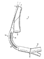
次に、図面を参照すると、患者の声門開口部へ気道通路を提供するために患者に挿入するための喉頭マスク気道装置1が例示され、装置1は、気道チューブ2と、気道チューブ2に取り付けられたマスク3と、を具備し、マスク3は、遠位端5および近位端6を有する本体4と周辺膨張可能カフ7と出口8とを具備し、マスク3は、チューブ2と出口8との間の気体連通のために気道チューブ2に取り付けられており、装置1は、患者の生体構造による出口8の閉塞を防止する手段をさらに具備し、この手段は、サポート(ドレーンチューブ)11と、気体がサポートを過ぎて出口8から流れるのを可能にする導通路28aと、を具備する。
図面から見ることができるように、装置1は、全体的な外観の観点からいえば、喉頭マスク気道装置のすべてでなければその大半を作り上げる基本部品、すなわち、気道チューブ2と、本体部品4含むマスク3と、カフ7と、から構成されるという点で、先行技術の装置に幾分類似している。
説明目的のために、装置1の区域に参照名を割り当てることが適切であり、したがって、図2〜6を参照すると、装置1は、背側部14と、腹側部15と、近位端16(患者ではなく、ユーザに最も近い端という意味で)と、遠位端17と、左右の側部18および19を有する。
Referring now to the drawings, illustrated is a laryngeal mask airway device 1 for insertion into a patient to provide an airway passage to the patient's glottic opening, the device 1 being attached to the
As can be seen from the drawings, the device 1 comprises, from an overall appearance point of view, the basic components that make up most if not all of the laryngeal mask airway device: the
For illustrative purposes, it is appropriate to assign a reference name to the area of the device 1, so that with reference to FIGS. 2-6, the device 1 has a dorsal portion 14, a
最初に気道チューブ2を参照すると、例示された実施形態において、チューブは、比較的剛性のあるPVC材料、たとえば、ショア90Aカラライト(Colorite)PVCを具備し、適切に生体構造的にカーブした形状に成形されている。チューブ2は、曲げられた場合には元々の形状に戻るように、幾分の柔軟性を有する。このように弾性的に変形可能であるが、装置1を患者内に挿入するのを補助するのを可能にするほど十分な剛性があり、ハンドルおよびガイドとして作用する。この実施形態において、気道チューブ2は、多くの先行技術の装置がそうであるような円形の断面は有さず、代わりに、背部/腹部方向に圧縮され、これは、形状が自然の気道の形状をほぼ模倣するため、装置1の正確な挿入を補助し、捩れを防止するのを助け、患者にとって快適な位置決めを補助する。この実施形態において、気道チューブ2の各側部18、19は、近位端から遠位端へチューブの長さの大半を延在する溝またはチャネル20を含む。これらの溝20は、気道チューブ2が潰れるか捩れるのを防止するのをさらに補助する。内側に、溝20は、側部18および19の内側表面に沿ってリッジを形成する。
Referring initially to the
次に、図13を参照すると、これは、装置1の分解図を示し、気道チューブ2が、マスク3を気道チューブにはみ出し成形することによって、マスク3の取付を可能にするように配置された表面22aを備えたフレア状遠位端22を含むのを見ることができる。このようにして、気道チューブ2自体が、装置1の形成に使用されるプレモールドを形成し、これは実質的に製造を容易にする。特に注目すべきなのは、気道チューブの背部モールド表面23(図13)である。この表面23は、フレア状遠位端22に位置し、背部壁2cの外側背部表面2aと内側背部表面2bとの間に延在する平らなランドの形態を取る。これは、任意の貫通穴2dを含み、後述されるように、はみ出し成形されたバックプレート4がチューブ2に係止するのを可能にする。この特徴は、気道チューブ2およびマスク3を作り上げる異なる材料の間のしっかりした接続を確実にするのを助ける。
Reference is now made to FIG. 13, which shows an exploded view of the device 1, with the
気道チューブ2のさらなる特徴は、食道ドレーンチューブ41である。このドレーンチューブ41は、気道チューブ2内に位置し、これを通って一方の端から他方へ中心に延在し、この実施形態では、気道チューブ2の背部壁2cの内側表面2bに接触するように配置され、各側部では、それが走るのに通る浅いチャネルを形成する隆起した滑らかな壁2cで境界づけられている。
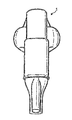
気道チューブ2の近位端には、たとえば図12および13に且つ図9の断面に示されるように、コネクタ42が設けられている。コネクタ42は、コネクタ本体43と、任意の嵌合片44と、コネクタプラグ45と、を具備する。コネクタ本体43および嵌合片44は、形状および寸法が、気道チューブ2の近位端の内側形状に対応し、その内部に嵌るようする。コネクタ本体43は、垂直に延在する周辺フランジ46を有し、その円周の1つの点でタブ47内に延在する。コネクタプラグ45は、接着剤またはフランジ46に加えられる他の適切な手段によって、コネクタ本体43に取り付けられる。コネクタプラグ45は、大きなボア48および小さなボア49を具備し、これらは両方とも、コネクタプラグ45の遠位端で共通房50内に導き、そこでコネクタ本体43に接着する。ドレーンチューブ41は、小さいボア49内にこれを通って延在し、気道チューブ2のボアおよびドレーンチューブ41のボアが互いから分離されるようにする。
A further feature of the
A
次に、マスク3に移ると、マスク3は、2つの部品、すなわち、バックプレート(背板)と称されることが多い本体部品4と、周辺カフ7とから構成される。
バックプレート4は、これらの実施形態では、ショア50Aヴィセーン(Vythene)PVC+PUから成形することによって形成されている。この材料は、気道チューブ2の材料よりも、実質的により柔らかく、より変形可能である。
次に、図23を参照すると、バックプレート4は、背部または腹部の方向から見たときに、略長円のモールディングを具備し、滑らかな背部表面24と、形成された腹部表面24a(図17)と、近位結合部分24bと、遠位先端61と、を有する。
Next, moving to the mask 3, the mask 3 is composed of two parts, that is, a main body part 4 often referred to as a back plate (back plate) and a peripheral cuff 7.
In these embodiments, the back plate 4 is formed by molding from Shore 50A Vythene PVC + PU. This material is substantially softer and more deformable than the material of the
Next, referring to FIG. 23, the back plate 4 has a substantially oval molding when viewed from the back or abdominal direction, and has a
背部表面24は、一方の側部から他方の側部へ凸状湾曲を有し、気道チューブ2の背部表面の湾曲に対応し、且つ、長手方向に更に曲がり、結合部分24bで開始する湾曲を有し、一定の率の湾曲で遠位先端61へ向けて延在する。結果として、先端61は、気道チューブの遠位端に対して腹部側に偏倚し、組み立てられた装置1で、遠位先端61の変位の程度は、患者の生体構造に適するマスクの湾曲を生成するために、およそ20mmまたは10度である。挿入時に、先端61のこの変位は、挿入経路で「隅を曲がる」際にマスクを補助する。
The
腹側部から見たときに、バックプレート4の一体的に成形された構造物を最良に見ることができる(図4、7、12、17)。バックプレートの腹側部24aの正確な形状は、特に、図11A〜11Kに示された断面図および図7の拡大斜視図に例示されている。図12に示された分解図を参照すると、バックプレート4の背部表面24の凸状湾曲は、腹側部の対応する凹状湾曲に酷似している。このようにして、腹部表面24aは、遠位先端61へ向けて傾斜する浅く細長いチャネルを形成する。チャネルは、壁26および床26aを有する。
チャネル壁26は、対応して形状づけられた、長手方向に延在する凸状外側表面25を形成する。各壁26は、近位結合部分24bから遠位先端61へ向けてバックプレート4の実質的に長さ全体を長手方向に延在する。各壁26はまた、凸状内側表面28も有するが、チャネルの床へ直角の角度で終端するのではなく、各壁26のカーブは継続し、壁はチャネル上へ戻ってカーブし、内向きに延在するウェブ27で終端する(図7参照)。側壁26の内側表面28は、下へカーブし、チャネルの床を形成するが、合流はせず、それは、チャネルの基部または床が、長手方向に延在する一体的に成形された導管によって二分されるからであり、それは、結合部分24bから遠位先端61へ長さ全体をそれに沿って延在する食道ドレーンチューブ11である。このようにして、チャネルは、3本の長手方向に延在する導通路をその内側表面に有し、組み立てられた装置1の小さい気体導通路である2本の開口外側導通路28aと、その間に隔壁を形成する中心ドレーンチューブ11と、であるのを見ることができる。
When viewed from the ventral side, the integrally molded structure of the back plate 4 can best be seen (FIGS. 4, 7, 12, 17). The exact shape of the
The
次に、ドレーンチューブ(サポート)11をより詳細に参照すると、上壁部分11aであるチャネルの床から最も遠い壁部位が、側壁26の内向きに延在するウェブ27と類似レベルにあるように、チューブ11が十分な直径を有することが見られる(図11K)。さらに、上壁部分11aはまたそれ自体が、外向きに延在するウェブ30を有し、これは、ウェブ27の対応して傾斜した縁へ向けて傾くが、合流しない。このようにして、ドレーンチューブ11の上部分11aの上部表面11b(図7)およびウェブ27、30は、一緒に、全3本の導通路11、28aが走るレベルより下で、表面11cを画成する。
次に、特に図9を参照すると、ドレーンチューブ11は、その近位結合部分24bから遠位先端61へバックプレート4の全長を延在するが、導通路28aは、バックプレート4の全長を延在せず、代わりに、その長さに沿って約半分ほどで終端するのを見ることができる。導通路28aの床31は、バックプレート4の遠位先端61へ向けて延在するときに穏やかに上方へ反れ、ついには、ウェブ27および30の位置にほぼ等しい位置で終端する。
Referring now to the drain tube (support) 11 in more detail, the wall portion furthest from the channel floor, the
Next, with particular reference to FIG. 9, the
図12および21且つ22に例示されるように、ドレーンチューブ11は、遠位先端61へ延在し、開口12に終端する。このようにして、ドレーンチューブ11の端部位11eは、バックプレート4の端を過ぎて突出する。この端部位11eには、背部ウェビング11aが設けられ、これは、それのいずれかの側部へ、それのまわりに延在し、フードまたはポケット36aを形成し、その円周のまわりに端セクション11eを取り囲む。フードまたはポケット36aは、開口12の円周のまわりでドレーンチューブ11の遠位端に取り付けられている。このフードまたはポケット36aは、遠位先端61でバックプレート4の材料に一体的に形成される。これは、ドレーンチューブ開口12の円周を完全に囲繞しそれから延在し、それらの間のジョイントは滑らかである。例示されたように、フードの腹部の範囲は、背部の範囲よりも限定されており、背部の範囲は、バックプレート4の近位端へ向けて戻ったほぼ中間である。図11の断面A−Aを参照すると、ドレーンチューブ11が、垂直に延在するウェブ62によって、その左右の側部におよび背部表面に支持されるのを見ることができる。これらのウェブ62は、一体的に形成され、開口12から戻って、端部位11eがバックプレート4の範囲に合流する点へ延在する。例示された実施形態において、背部ウェブ62は、ドレーンチューブから実質的に垂直に延在するが、好適な実施形態では、90度未満の角度で、一方の側部へまたは他方の側部へ延在する。
As illustrated in FIGS. 12 and 21 and 22, the
マスク3の第2の部品は、周辺カフ7である。カフ7は、この実施形態では、ブロー成形されたPVCであり、中心開口部7aと、膨張ポート38を備えた比較的深い近位端37と、「楔」の形体に傾斜する比較的浅い遠位端7bと、を有する略楕円形の膨張可能リングの形態を取る。認識されるように、特に、図12および13に示された分解図から、カフ7は、1片に一体的に形成されている。背側部表面積の腹側部表面積に対する率が背側部を支持するように、楔形体が設けられる。このようにして、収縮したときには、カフ7の遠位端7bは、背側部から腹側部へ偏倚してカールする。
The second part of the mask 3 is a peripheral cuff 7. The cuff 7 is, in this embodiment, a blow molded PVC, a central opening 7a, a relatively deep proximal end 37 with an
組み立てられた装置1において、ドレーンチューブ41は、気道チューブ2内に挿入され、これが近位端16から突出するようにする。コネクタ42は、コネクタ本体43および嵌合片44を近位端16内に挿入することによって、気道チューブ2に取り付けられる。部品は、締まり嵌めであり、接着剤によって固定することができる。プラグ45がフランジ46を経由してコネクタ本体43に取り付けられ、ドレーンチューブ41が小さなボア49内に進み、その口でまたはそれに隣接して終端するようにする。このようにして、小さなボア49が単にドレーンチューブ41に流体連通するだけであり、大きなボア48は単に気道チューブ2の内部に流体連通するだけであるのが見られる。
In the assembled device 1, the
気道チューブ2は、既に形成されたチューブ2にバックプレート4をはみ出し成形することによって便利に、バックプレート4に取り付けられる。このようにして、バックプレート4の結合部分24bは、気道チューブ2の背部弓に成形される。確実な取付は、成形が発生する増加した表面積を提供する表面22a、23、および、バックプレート材料が中に流れることができる貫通穴2dによって容易にされる。ドレーンチューブ41は、一体的に成形されたドレーン11に、流体密封式に接続される。
The
カフ7は、図12および13に例示されたように、カフ7の楔形体の遠位端7bをバックプレート4の遠位先端61でフードまたはポケット36a内に挿入することによってバックプレート4に結合され、楔表面39がフード36aの内側表面36bに噛み合い、カフ7の内側周囲のセクションがバックプレート壁26の凸状外側表面25に噛み合うようにする。カフ7は、フードに結合され、フードとカフとの間の空間が気密であるようにし、この実施形態では、カフには、「ピンチオフ(狭窄開放)」40(図21)が設けられ、カフ7およびフード36aを流体連通させ、そのため、カフ7自体に加えて、フードの空気空間もまた膨張することができる。しかし、カフ7のピンチオフは、カフの遠位端へ向けて距離全体を延在せず、膨張の圧力が開口12を閉塞するのを防止する。カフの近位背部表面は、気道チューブ2の遠位端22の腹部弓に結合される。このようにして、食道ドレーンを組み込む先の装置とは異なり、本発明では、ドレーン11はカフ7を穿刺せず、製造をより容易にすることが認識される。さらに、ドレーンがカフを穿刺する先行技術の装置では、カフは、遠位先端でドレーンチューブの円周のまわりに固定して取り付けられなければならない。たとえば接着剤でのそのような固定取付は、先端を硬くする可能性があり、ドレーンチューブが、収縮した平らな装置で折り畳まれるのを妨げるが、それは、マスクが、生体構造の湾曲のまわりに容易に進むことを可能にするために極めて望ましいことである。加えて、ドレーンチューブのカフジョイントへの鋭い湾曲が、亀裂を招くことが非常に多い。本発明では、ドレーンチューブ11はフード36aと一体的に成形され、これが、事実上、遠位先端で第2のカフまたは小さなカフを形成するため、これらの問題は回避される。
The cuff 7 is coupled to the back plate 4 by inserting the wedge-shaped
認識されるように、装置1の気道は、気体が患者へ進むのに通る導通路であり、気道チューブ2のボア2aによって設けられ、これは、フレア状遠位端22で終端する。フレア状遠位端22は、バックプレート4およびカフ7とともに、気体用の出口8を画成し、これは、気体が進んでもよい3本のルートを含み、すなわち、主要気体導通路28b、および、2本の小さな気体導通路28aである。
As will be appreciated, the airway of the device 1 is a conduit through which gas travels to the patient and is provided by the
使用の際には、収縮した装置1が、この種類の装置の通常のやり方で、患者内に挿入される。上記に注記されたように、気道チューブ2が比較的剛性があり、ユーザは、これを把持することができ、これを使用して装置1を患者内にガイドし、一方、バックプレートの比較的柔らかくより柔軟な材料は、マスクがより容易に変形し、生体構造を損傷することなく挿入経路と折り合いを付け、且つ、その最適な形状に戻り、挿入の最も遠い範囲で良好な封止が達成されるのを確実にする。バックプレート4と気道チューブ2との間の接合箇所に対する遠位先端61の腹部変位は、挿入の容易さをさらに高めるが、それは、遠位先端61がそれによって、挿入経路の「曲げ」と折り合いを付けるための最適な角度で呈されるからである。比較的剛性のある材料、たとえば、PVC等から形成された装置では、しばしば使用されるLSRとは対照的に、挿入を容易にし、封止を高める際に、これらの特徴は特に重要である。
In use, the deflated device 1 is inserted into the patient in the usual manner of this type of device. As noted above, the
次に、成形バックプレート4の特徴を参照すると、バックプレート4の材料に一体的に成形されたドレーンチューブを提供することによって、接着剤で適所に結合された別個のドレーンチューブの存在によって生じた先行技術の設計における固さおよび製造の困難さの問題を緩和することができる。
本発明のバックプレートで、中心に位置するドレーンチューブ11と小さな気体導通路28aとの組み合わせが、患者の生体構造の一部によって気道が閉塞する問題を解決するのを補助する。小さな気体導通路28aは、「鼻孔」と考えることができ、これを通って気体が、主要出口28bがたとえば患者の喉頭蓋によって閉塞された場合でさえ、患者内に進み続けてもよく、喉頭蓋は隔壁にある。特に図11Iおよび11Jに例示されたように、ウェブ27、30は、導通路28a上に部分閉鎖を形成し、喉頭蓋等の構造物が導通路28a内に落ちてこれを遮るのを防止し、且つ、バックプレート4を側方向圧縮に対してより抵抗性のあるようにする。この実施形態において、ドレーン11は、導通路28aの間に便利な隔壁を形成するが、食道ドレーンのない装置では、単に、成形によってバックプレートの材料に、中実隔壁を形成することができるだけであることが認識される。加えて、より大きな数の導通路28aを設けることができる。
Referring now to the characteristics of the molded backplate 4, it was caused by the presence of a separate drain tube bonded in place with an adhesive by providing a drain tube integrally molded to the material of the backplate 4. Stiffness and manufacturing difficulties in prior art designs can be mitigated.
In the backplate of the present invention, the combination of the centrally located
Claims (13)
前記装置は、気道チューブ(2)と、前記気道チューブに取り付けられたマスク(3)と、を具備し、
前記マスクは、遠位端(5)、近位端(6)、背部表面(24)及び腹部表面(24a)を有する本体(4)と周辺膨張可能なカフと(7)を含むと共に気体用の出口(8)を画成し、且つ前記マスクとチューブの間の気体連通のために該気道チューブに接続され、
前記装置は、患者の生体構造による、前記出口の閉塞を防止する手段をさらに具備し、前記手段は、サポート(11)と、該サポートを抜けて前記出口の外を流れるのを許可する導通路(28a)と、を具備し、
前記出口は本体の腹側に画成されている床を含み、前記サポートは、前記床のレベルより上に閉塞生体構造物を支持するように配置され、気体が前記構造物を支持した下を流れるのを可能にし、
前記サポート表面は、前記出口の前から前記遠位端へ向けて延在する、中央に配置された長手方向垂直部に設けられ、前記サポート表面を前記腹側部の位置より盛り上げてある、喉頭マスク気道装置。 A laryngeal mask airway device for insertion into a patient to provide an airway passage to the patient's glottal opening,
The device comprises an airway tube (2) and a mask (3) attached to the airway tube,
The mask includes a body (4) having a distal end (5) , a proximal end (6) , a back surface (24) and an abdominal surface (24a) , a peripherally inflatable cuff and (7) and for gas Is connected to the airway tube for gas communication between the mask and the tube,
The device further comprises means for preventing obstruction of the outlet due to the anatomy of the patient, the means being a support (11) and a conduction path allowing flow through the support and out of the outlet. and (28a), provided with a,
The outlet includes a floor defined on the ventral side of the body, and the support is positioned to support an occluded anatomy above the level of the floor, and under which gas supports the structure. Allowing it to flow,
The support surface is provided in a centrally disposed longitudinal vertical portion extending from the front of the outlet toward the distal end, and the support surface is raised above the ventral position. Mask airway device.
Applications Claiming Priority (3)
| Application Number | Priority Date | Filing Date | Title |
|---|---|---|---|
| GB0510951.7 | 2005-05-27 | ||
| GBGB0510951.7A GB0510951D0 (en) | 2005-05-27 | 2005-05-27 | Laryngeal mask airway device |
| PCT/GB2006/001915 WO2006125990A1 (en) | 2005-05-27 | 2006-05-24 | Laryngeal mask airway device |
Related Child Applications (1)
| Application Number | Title | Priority Date | Filing Date |
|---|---|---|---|
| JP2012123217A Division JP6105863B2 (en) | 2005-05-27 | 2012-05-30 | Laryngeal mask airway device |
Publications (2)
| Publication Number | Publication Date |
|---|---|
| JP2008541820A JP2008541820A (en) | 2008-11-27 |
| JP5089579B2 true JP5089579B2 (en) | 2012-12-05 |
Family
ID=34834809
Family Applications (7)
| Application Number | Title | Priority Date | Filing Date |
|---|---|---|---|
| JP2008512915A Active JP4828598B2 (en) | 2005-05-27 | 2006-05-24 | Laryngeal mask airway device |
| JP2008512912A Ceased JP2008541817A (en) | 2005-05-27 | 2006-05-24 | Laryngeal mask airway device |
| JP2008512913A Active JP5219209B2 (en) | 2005-05-27 | 2006-05-24 | Laryngeal mask airway device and manufacturing method thereof |
| JP2008512916A Active JP5089579B2 (en) | 2005-05-27 | 2006-05-24 | Laryngeal mask airway device |
| JP2012117796A Withdrawn JP2012179406A (en) | 2005-05-27 | 2012-05-23 | Laryngeal mask airway device |
| JP2012123217A Active JP6105863B2 (en) | 2005-05-27 | 2012-05-30 | Laryngeal mask airway device |
| JP2012163647A Active JP5711701B2 (en) | 2005-05-27 | 2012-07-24 | Laryngeal mask airway device |
Family Applications Before (3)
| Application Number | Title | Priority Date | Filing Date |
|---|---|---|---|
| JP2008512915A Active JP4828598B2 (en) | 2005-05-27 | 2006-05-24 | Laryngeal mask airway device |
| JP2008512912A Ceased JP2008541817A (en) | 2005-05-27 | 2006-05-24 | Laryngeal mask airway device |
| JP2008512913A Active JP5219209B2 (en) | 2005-05-27 | 2006-05-24 | Laryngeal mask airway device and manufacturing method thereof |
Family Applications After (3)
| Application Number | Title | Priority Date | Filing Date |
|---|---|---|---|
| JP2012117796A Withdrawn JP2012179406A (en) | 2005-05-27 | 2012-05-23 | Laryngeal mask airway device |
| JP2012123217A Active JP6105863B2 (en) | 2005-05-27 | 2012-05-30 | Laryngeal mask airway device |
| JP2012163647A Active JP5711701B2 (en) | 2005-05-27 | 2012-07-24 | Laryngeal mask airway device |
Country Status (18)
| Country | Link |
|---|---|
| US (9) | US9522245B2 (en) |
| EP (5) | EP1885424B1 (en) |
| JP (7) | JP4828598B2 (en) |
| KR (4) | KR20080031213A (en) |
| CN (6) | CN102688548B (en) |
| AR (4) | AR057038A1 (en) |
| AU (4) | AU2006251000B2 (en) |
| BR (4) | BRPI0610655A2 (en) |
| CA (4) | CA2609472C (en) |
| DE (2) | DE202006021004U1 (en) |
| ES (2) | ES2592912T3 (en) |
| GB (1) | GB0510951D0 (en) |
| IL (4) | IL187573A0 (en) |
| MX (4) | MX2007014904A (en) |
| RU (4) | RU2411962C2 (en) |
| TW (4) | TW200706196A (en) |
| WO (4) | WO2006125989A1 (en) |
| ZA (4) | ZA200710522B (en) |
Families Citing this family (68)
| Publication number | Priority date | Publication date | Assignee | Title |
|---|---|---|---|---|
| US5881723A (en) | 1997-03-14 | 1999-03-16 | Nellcor Puritan Bennett Incorporated | Ventilator breath display and graphic user interface |
| GB0218868D0 (en) | 2002-08-14 | 2002-09-25 | Nasir Muhammed A | Improved airway management device |
| ZA200601332B (en) | 2003-08-14 | 2007-05-30 | Nasir Muhammed Aslam | Improved airway device |
| GB0510951D0 (en) | 2005-05-27 | 2005-07-06 | Laryngeal Mask Company The Ltd | Laryngeal mask airway device |
| US9084912B2 (en) * | 2005-10-19 | 2015-07-21 | Performance Health Systems, Llc | Systems and methods for administering an exercise program |
| US8021310B2 (en) | 2006-04-21 | 2011-09-20 | Nellcor Puritan Bennett Llc | Work of breathing display for a ventilation system |
| US7784461B2 (en) | 2006-09-26 | 2010-08-31 | Nellcor Puritan Bennett Llc | Three-dimensional waveform display for a breathing assistance system |
| GB2454199A (en) * | 2007-10-30 | 2009-05-06 | Laryngeal Mask Co Ltd | Laryngeal mask with tape tab |
| GB0821291D0 (en) * | 2008-11-21 | 2008-12-31 | Nasir Muhammed A | Improved airway device |
| CH699987A1 (en) * | 2008-11-27 | 2010-05-31 | Deltona Innovations Ag | Laryngeal mask with a nozzle. |
| CH699986A1 (en) * | 2008-11-27 | 2010-05-31 | Deltona Innovations Ag | Laryngeal Mask with Oesophagealdurchgang. |
| GB0903654D0 (en) | 2009-03-03 | 2009-04-15 | Laryngeal Mask Company The Ltd | Artificial airway device |
| DE202010018619U1 (en) | 2009-07-06 | 2018-11-07 | Teleflex Life Sciences Unlimited Company | Artificial airway |
| WO2011017756A1 (en) | 2009-08-13 | 2011-02-17 | Ultimate Medical Pty. Ltd. | Pressure indicator |
| US8335992B2 (en) | 2009-12-04 | 2012-12-18 | Nellcor Puritan Bennett Llc | Visual indication of settings changes on a ventilator graphical user interface |
| US9119925B2 (en) | 2009-12-04 | 2015-09-01 | Covidien Lp | Quick initiation of respiratory support via a ventilator user interface |
| US8924878B2 (en) | 2009-12-04 | 2014-12-30 | Covidien Lp | Display and access to settings on a ventilator graphical user interface |
| US9262588B2 (en) | 2009-12-18 | 2016-02-16 | Covidien Lp | Display of respiratory data graphs on a ventilator graphical user interface |
| US8499252B2 (en) | 2009-12-18 | 2013-07-30 | Covidien Lp | Display of respiratory data graphs on a ventilator graphical user interface |
| WO2011106754A1 (en) | 2010-02-27 | 2011-09-01 | King Systems Corporation | Laryngeal tube |
| GB201010647D0 (en) * | 2010-06-24 | 2010-08-11 | Docsinnovent Ltd | Stopper device |
| GB201016562D0 (en) * | 2010-10-01 | 2010-11-17 | Laryngeal Mask Company The Ltd | Artificial airway device |
| US9675772B2 (en) * | 2010-10-15 | 2017-06-13 | The Laryngeal Mask Company Limited | Artificial airway device |
| ES2881328T3 (en) | 2010-11-12 | 2021-11-29 | Teleflex Medical Inc | Nasal therapy spray |
| DK201001052A (en) * | 2010-11-19 | 2011-11-10 | Ambu As | A tracheal intubation guide |
| CN109200416A (en) * | 2011-02-02 | 2019-01-15 | 梅田有限公司 | improved artificial airway |
| USD688787S1 (en) * | 2011-06-08 | 2013-08-27 | Intersurgical Ag | Airway device cap and strap holder |
| USD693920S1 (en) | 2011-06-08 | 2013-11-19 | Intersurgical Ag | Airway device |
| USD712244S1 (en) | 2011-09-23 | 2014-09-02 | Intersurgical Ag | Medical device package |
| GB201120628D0 (en) | 2011-11-30 | 2012-01-11 | Laryngeal Mask Company The Ltd | Endoscopy device |
| USD761952S1 (en) | 2012-07-27 | 2016-07-19 | Docsinnovent Limited | Airway device |
| GB201201438D0 (en) * | 2012-01-27 | 2012-03-14 | Docsinnovent Ltd | Improved stopper device |
| US10362967B2 (en) | 2012-07-09 | 2019-07-30 | Covidien Lp | Systems and methods for missed breath detection and indication |
| CN102908704A (en) * | 2012-10-31 | 2013-02-06 | 南昌贝欧特医疗设备有限公司 | Laryngeal mask |
| GB201314631D0 (en) | 2013-08-15 | 2013-10-02 | Teleflex Life Sciences | Endoscopy device |
| CN103432670B (en) * | 2013-09-10 | 2015-06-10 | 广州维力医疗器械股份有限公司 | Laryngeal mask breather tube device and manufacturing method thereof |
| KR101508131B1 (en) * | 2013-09-26 | 2015-04-07 | 정민호 | Airway device |
| GB201317596D0 (en) * | 2013-10-04 | 2013-11-20 | Teleflex Life Sciences | Biteblock |
| FR3014258B1 (en) | 2013-12-02 | 2017-02-17 | Schneider Electric Ind Sas | FIRE PROTECTION DEVICE OF A STARTER-CONTROLLER DEVICE OF AN ELECTRICAL INSTALLATION |
| GB2522403B (en) * | 2013-12-17 | 2017-09-13 | Aslam Nasir Muhammed | Airway device with flexible divider |
| GB2546167B (en) * | 2013-12-17 | 2018-02-28 | Aslam Nasir Muhammed | Intubating Airway Device |
| DK177742B1 (en) * | 2014-01-24 | 2014-05-19 | Ambu As | A laryngeal mask with a bite absorbing connector |
| JP6378886B2 (en) * | 2014-01-31 | 2018-08-22 | 大研医器株式会社 | Laryngeal mask |
| SG2014011720A (en) | 2014-02-10 | 2015-09-29 | Craig Wight Ronald | An airway management device and method of manufacture |
| CA158881S (en) * | 2014-03-28 | 2015-05-04 | Teleflex Life Sciences | Laryngeal mask |
| US9950129B2 (en) | 2014-10-27 | 2018-04-24 | Covidien Lp | Ventilation triggering using change-point detection |
| US9283342B1 (en) * | 2015-03-04 | 2016-03-15 | Glenn P. Gardner | Endotracheal tube insertion device |
| CN105214188B (en) * | 2015-11-09 | 2017-07-28 | 汤立 | Many tube chamber laryngeal masks |
| USD842456S1 (en) | 2015-12-15 | 2019-03-05 | Intersurgical Ag | Airway device |
| AU2017282981A1 (en) | 2016-03-31 | 2018-10-18 | Teleflex Life Sciences Llc | Fixation device for a laryngeal mask |
| KR101789171B1 (en) | 2016-07-13 | 2017-10-25 | 한양대학교 산학협력단 | Apparatus for free airway and guiding intubation tube |
| US10821248B2 (en) | 2017-02-06 | 2020-11-03 | David James Durkin | Courier airway device |
| AU201714823S (en) | 2017-02-27 | 2017-10-12 | Teleflex Life Sciences Unlimited Co | Laryngeal mask airway device |
| CN107137807B (en) * | 2017-05-02 | 2020-06-09 | 浙江简成医疗科技有限公司 | Laryngeal mask |
| US10314995B2 (en) | 2017-08-17 | 2019-06-11 | Yang Sun | Endotracheal intubation and supraglottic airway device |
| CN107737394A (en) * | 2017-11-15 | 2018-02-27 | 方峥评 | A kind of Puffer-type rinses laryngeal mask |
| US10744287B2 (en) | 2017-11-29 | 2020-08-18 | Airway Medix S.A. | Laryngeal mask cuffs |
| US10173022B1 (en) | 2017-11-29 | 2019-01-08 | Airway Medix S.A. | Laryngeal mask cuff |
| US10369311B2 (en) | 2017-11-29 | 2019-08-06 | Airway Medix S.A. | Laryngeal mask cuff |
| GB201720733D0 (en) | 2017-12-13 | 2018-01-24 | Ashkal Development Ltd | Airway device |
| WO2020162832A1 (en) | 2019-02-08 | 2020-08-13 | Ronald Craig Wight | An airway management device and methods of manufacturing an object |
| EP3698836A1 (en) * | 2019-02-25 | 2020-08-26 | Visual Oxy, S.L. | Laryngeal mask |
| CN111298257A (en) * | 2020-03-25 | 2020-06-19 | 苏州大学附属第二医院 | Special three-head multifunctional laryngeal mask for airway surgery |
| CN111660570B (en) * | 2020-05-07 | 2021-08-31 | 江门市康馨医疗器械有限公司 | Laryngeal mask, hot-melt welding method and hot-melt welding equipment |
| US11672934B2 (en) | 2020-05-12 | 2023-06-13 | Covidien Lp | Remote ventilator adjustment |
| BR112022023328A2 (en) * | 2020-05-18 | 2022-12-20 | Pedro Luis Bravo Garcia | ENDOTRACHEAL DEVICE FOR MECHANICAL VENTILATION OF A PATIENT |
| CN112007248A (en) * | 2020-08-05 | 2020-12-01 | 朱燕 | Visual laryngeal mask auxiliary mounting system for department of pediatrics |
| KR102559960B1 (en) | 2022-12-26 | 2023-07-25 | 주형준 | Laryngeal mask for tracheal intubation |
Family Cites Families (210)
| Publication number | Priority date | Publication date | Assignee | Title |
|---|---|---|---|---|
| US2099127A (en) | 1936-12-30 | 1937-11-16 | Foregger Co Inc | Pharyngeal bulb gasway |
| US2839788A (en) * | 1953-04-24 | 1958-06-24 | Dembiak Matthew | Method of making hollow plastic or rubber articles |
| US2862498A (en) | 1957-06-14 | 1958-12-02 | Don J Weekes | Endotracheal tube |
| US3529596A (en) | 1968-04-03 | 1970-09-22 | Charles G Garner | Automatic intermittent tracheotomy tube cuff inflator-deflator |
| US3554673A (en) * | 1969-01-31 | 1971-01-12 | Sage Instr Inc | Syringe pump |
| US3683908A (en) * | 1969-10-20 | 1972-08-15 | Tantrimudalige Anthony Don Mic | Apparatus for sealing the oesophagus and providing artificial respiration |
| US3774616A (en) | 1972-02-01 | 1973-11-27 | Perry Plastics Inc | Endotracheal tube holder and airway |
| US3794036A (en) * | 1972-08-02 | 1974-02-26 | R Carroll | Pressure regulated inflatable cuff for an endotracheal or tracheostomy tube |
| US4104357A (en) * | 1973-01-10 | 1978-08-01 | Monster Molding, Inc. | Method of rotational molding about plural axes at low rotational speeds |
| US3931822A (en) * | 1974-02-26 | 1976-01-13 | Marici Frank N | Automatic alternating cuff endo tracheal tube inflator |
| FR2298147A1 (en) * | 1975-01-17 | 1976-08-13 | Ucc Union Chimique Cont | DEVICE GIVING THE ALARM IN CASE OF DISCONNECTION OF A HOSE, IN PARTICULAR OF A RESPIRATOR |
| US4116201A (en) | 1976-12-20 | 1978-09-26 | The Kendall Company | Catheter with inflation control device |
| US4134407A (en) * | 1977-03-25 | 1979-01-16 | Elam James O | External pressure-volume monitor for endotracheal cuff |
| US4159722A (en) * | 1977-03-28 | 1979-07-03 | Sherwood Medical Industries, Inc. | Pressure regulator for endotracheal tube cuff or the like |
| US4178938A (en) | 1977-06-24 | 1979-12-18 | Au Anthony S | Pressure control systems |
| US4178940A (en) | 1977-06-24 | 1979-12-18 | Au Anthony S | Pressure control systems |
| US4166467A (en) | 1977-08-08 | 1979-09-04 | Metatech Corporation | Bite block for endotracheal tube |
| US4351330A (en) | 1978-01-30 | 1982-09-28 | Scarberry Eugene N | Emergency internal defibrillation |
| US4231365A (en) | 1978-01-30 | 1980-11-04 | Scarberry Eugene N | Emergency resuscitation apparatus |
| US4285340A (en) * | 1979-03-16 | 1981-08-25 | Gezari Walter A | Apparatus for controlling the pressure in a tracheal cuff |
| US4256099A (en) * | 1979-03-21 | 1981-03-17 | Dryden Gale E | Two-tube resuscitation system |
| JPS5667383A (en) * | 1979-11-08 | 1981-06-06 | Mitsui Petrochem Ind Ltd | Thixotropic agent |
| US4446864A (en) * | 1980-07-10 | 1984-05-08 | Watson Robert L | Emergency ventilation tube |
| US4425911A (en) | 1981-07-27 | 1984-01-17 | Raymond Luomanen | Bite-block |
| GB2111394B (en) * | 1981-12-16 | 1985-09-11 | Archibald Ian Jeremy Brain | Artificial airway device |
| US4531330A (en) * | 1982-02-01 | 1985-07-30 | Phillips William E | Bed/shelter unit |
| US4471775A (en) | 1982-09-07 | 1984-09-18 | Clair Michael W | Endotracheal tube cuff synchronizing system |
| US4501273A (en) * | 1982-09-30 | 1985-02-26 | Mcginnis Gerald E | Endotracheal tube with pressure controlled inflatable cuff |
| US4526196A (en) * | 1983-01-26 | 1985-07-02 | Nayan S. Shah | Gas pressure measuring and regulating device and method |
| US4583917A (en) * | 1983-06-17 | 1986-04-22 | Shah Nayan S | Pressure regulating and monitoring device |
| DE3327342A1 (en) | 1983-07-29 | 1985-02-07 | Peter 7800 Freiburg Pedersen | DEVICE FOR DETECTING AND EVALUATING THE PRESSURE IN THE BALLOON CUFF OF A CLOSED TRACHEAL TUBE |
| US4553540A (en) | 1983-08-16 | 1985-11-19 | Straith Richard E | Airway |
| US4689041A (en) * | 1984-01-20 | 1987-08-25 | Eliot Corday | Retrograde delivery of pharmacologic and diagnostic agents via venous circulation |
| JPS628766A (en) | 1985-07-03 | 1987-01-16 | 鳥取大学長 | Cuff pressure controller of gas insert tube with cuff |
| US4793327A (en) | 1986-01-21 | 1988-12-27 | Frankel Alfred R | Device for opening a patient's airway during automatic intubation of the trachea |
| JPS62186872A (en) * | 1986-02-14 | 1987-08-15 | 鳥取大学長 | Respiration pressure superposing type cuff pressure adjusting apparatus |
| US4700700A (en) | 1986-09-15 | 1987-10-20 | The Cleveland Clinic Foundation | Endotracheal tube |
| US5203320A (en) * | 1987-03-24 | 1993-04-20 | Augustine Medical, Inc. | Tracheal intubation guide |
| US4832020A (en) * | 1987-03-24 | 1989-05-23 | Augustine Scott D | Tracheal intubation guide |
| US5042469A (en) * | 1987-03-24 | 1991-08-27 | Augustine Medical, Inc. | Tracheal intubation guide |
| US4798597A (en) * | 1987-04-29 | 1989-01-17 | Sherwood Medical Co | Flexible composite intubation tube |
| GB2205499B (en) | 1987-06-05 | 1991-01-16 | Archibald Ian Jeremy Brain | Artificial airway device |
| US4924862A (en) * | 1987-08-19 | 1990-05-15 | Gary Levinson | Pressure controller and leak detector for tracheal tube cuff |
| US4850349A (en) * | 1987-12-04 | 1989-07-25 | Farahany Amir H | Endotracheal tube sealing cuff system |
| US4872483A (en) | 1987-12-31 | 1989-10-10 | International Medical Products, Inc. | Conveniently hand held self-contained electronic manometer and pressure modulating device |
| US4856510A (en) * | 1988-04-06 | 1989-08-15 | Kowalewski Ryszard J | Tracheal tube inflator |
| US5067496A (en) | 1988-04-07 | 1991-11-26 | Shiley Incorporated | Tracheostomy tube |
| US4972963A (en) * | 1988-10-31 | 1990-11-27 | Guarriello Henry J | Blow molded article with reverse lip |
| US4953547A (en) | 1989-01-26 | 1990-09-04 | Poole Jr Samuel E | Drug administering endotracheal respiration systems |
| GB2229367A (en) | 1989-03-22 | 1990-09-26 | Archibald Ian Jeremy Brain | Artificial airway device |
| US5169379A (en) | 1989-06-14 | 1992-12-08 | L-Vad Technology | In-series ventricular assist system and method of controlling same |
| US4981470A (en) * | 1989-06-21 | 1991-01-01 | Synectics Medical, Inc. | Intraesophageal catheter with pH sensor |
| JPH0339169A (en) * | 1989-07-06 | 1991-02-20 | B Hazaado Patrick | Percutaneous tracheotomic tube |
| US5042476A (en) * | 1989-08-10 | 1991-08-27 | Smith Charles A | Endotracheal tube protection arrangement |
| WO1991003207A1 (en) | 1989-09-08 | 1991-03-21 | Boston Scientific Corporation | Physiologic low stress angioplasty |
| US5174283A (en) | 1989-11-08 | 1992-12-29 | Parker Jeffrey D | Blind orolaryngeal and oroesophageal guiding and aiming device |
| US5038766A (en) | 1989-11-08 | 1991-08-13 | Parker Jeffrey D | Blind orolaryngeal and oroesophageal guiding and aiming device |
| GB9003857D0 (en) | 1990-02-21 | 1990-04-18 | Smiths Industries Plc | Medico-surgical tube assemblies |
| GB9026403D0 (en) * | 1990-12-05 | 1991-01-23 | Smiths Industries Plc | Pressure monitors |
| GB9102821D0 (en) | 1991-02-11 | 1991-03-27 | Brain Archibald Ian Jeremy | An intubating laryngeal mask airway |
| US5339808A (en) * | 1991-04-02 | 1994-08-23 | Don Michael T Anthony | Endotracheal-esophageal intubation devices |
| US5235973A (en) * | 1991-05-15 | 1993-08-17 | Gary Levinson | Tracheal tube cuff inflation control and monitoring system |
| US5795325A (en) * | 1991-07-16 | 1998-08-18 | Heartport, Inc. | Methods and apparatus for anchoring an occluding member |
| GB9119703D0 (en) * | 1991-09-14 | 1991-10-30 | Dingley John | Medico-surgical device |
| US5113875A (en) * | 1991-09-24 | 1992-05-19 | Bennett Trevor S | Inflatable leg-supporting bolster |
| US5241325A (en) * | 1991-10-31 | 1993-08-31 | Hewlett-Packard Company | Print cartridge cam actuator linkage |
| MX9301163A (en) * | 1992-03-05 | 1994-07-29 | Brain Archibald Ian Jeremy | LARINGEA MASK AND METHOD FOR ITS MANUFACTURE. |
| GB9204754D0 (en) * | 1992-03-05 | 1992-04-15 | Brain Archibald Ian Jeremy | Mould for manufacture of a laryngeal mask |
| US5273537A (en) | 1992-03-06 | 1993-12-28 | Scimed Life Systems, Inc. | Power-assisted inflation apparatus |
| US5421325A (en) * | 1992-04-30 | 1995-06-06 | Cinberg; James Z. | Endotracheal tube assembly and related method |
| US5546936A (en) * | 1992-05-19 | 1996-08-20 | Mallinckrodt Medical, Inc. | Tracheal tube with reinforced flexible segment |
| US5249571A (en) | 1992-05-21 | 1993-10-05 | Brain Archibald Ian Jeremy | Laryngeal clamp airway |
| US5241956A (en) | 1992-05-21 | 1993-09-07 | Brain Archibald Ian Jeremy | Laryngeal mask airway with concentric drainage of oesophagus discharge |
| DE4222220A1 (en) | 1992-07-07 | 1994-01-13 | Deutsche Aerospace | Procedure for measuring and regulating the pressure in the sealing sleeve of a tracheal tube |
| EP0580385B1 (en) | 1992-07-21 | 1996-05-08 | Archibald Ian Jeremy Dr. Brain | Laryngeal mask incorporating a reflectance oximeter |
| GB9215455D0 (en) | 1992-07-21 | 1992-09-02 | Brain Archibald Ian Jeremy | A laryngeal mask airway adapted to carry a reflecting-type oximeter |
| US5297547A (en) * | 1992-07-30 | 1994-03-29 | Brain Archibald Ian Jeremy | Laryngeal mask construction |
| ZA927931B (en) * | 1992-08-24 | 1994-04-14 | Donald Munro Miller | Breathing apparatus |
| US5355879A (en) | 1992-09-28 | 1994-10-18 | Brain Archibald Ian Jeremy | Laryngeal-mask construction |
| US5400771A (en) * | 1993-01-21 | 1995-03-28 | Pirak; Leon | Endotracheal intubation assembly and related method |
| US5331967A (en) * | 1993-02-05 | 1994-07-26 | Playa De Los Vivos S.A. | Tracheal intubation monitoring apparatus and method |
| US5546935A (en) * | 1993-03-09 | 1996-08-20 | Medamicus, Inc. | Endotracheal tube mounted pressure transducer |
| GB9312131D0 (en) * | 1993-06-11 | 1993-07-28 | Blatchford & Sons Ltd | Prosthesis control system |
| FR2709251B1 (en) | 1993-08-26 | 1995-11-10 | Georges Boussignac | Breathing assistance tube. |
| US5443063A (en) | 1993-08-31 | 1995-08-22 | The Johns Hopkins University | Cuffed oro-pharyngeal airway |
| US5551420A (en) | 1993-11-09 | 1996-09-03 | Cprx, Inc. | CPR device and method with structure for increasing the duration and magnitude of negative intrathoracic pressures |
| US5692498A (en) | 1993-11-09 | 1997-12-02 | Cprx, Inc. | CPR device having valve for increasing the duration and magnitude of negative intrathoracic pressures |
| US6062219A (en) * | 1993-11-09 | 2000-05-16 | Cprx Llc | Apparatus and methods for assisting cardiopulmonary resuscitation |
| US5459700A (en) | 1993-11-22 | 1995-10-17 | Advanced Cardiovascular Systems, Inc. | Manual timer control for inflation device |
| US5599301A (en) * | 1993-11-22 | 1997-02-04 | Advanced Cardiovascular Systems, Inc. | Motor control system for an automatic catheter inflation system |
| US5554673A (en) | 1993-11-29 | 1996-09-10 | Polygenex International, Inc. | Dip molded polyurethane film compositions |
| GB2285765B (en) * | 1994-01-12 | 1997-10-29 | Archibald Ian Jeremy Brain | Forming tool for use with a laryngeal mask |
| US5499625A (en) | 1994-01-27 | 1996-03-19 | The Kendall Company | Esophageal-tracheal double lumen airway |
| US5529582A (en) * | 1994-02-01 | 1996-06-25 | Fukuhara; Tomio | Apparatus for inserting laryngeal mask |
| US5582167A (en) | 1994-03-02 | 1996-12-10 | Thomas Jefferson University | Methods and apparatus for reducing tracheal infection using subglottic irrigation, drainage and servoregulation of endotracheal tube cuff pressure |
| JP3782123B2 (en) | 1994-05-31 | 2006-06-07 | 住友ベークライト株式会社 | Pharyngeal airway |
| GB9411215D0 (en) | 1994-06-04 | 1994-07-27 | Brain Archibald Ian Jeremy | A fibreoptic intubating laryngeal mask airway |
| SE503155C2 (en) * | 1994-07-28 | 1996-04-01 | Comasec International Sa | Methods and apparatus for functional control of breathing apparatus |
| US5569219A (en) | 1994-09-13 | 1996-10-29 | Hakki; A-Hamid | Collapsible catheter |
| GB9422224D0 (en) | 1994-11-03 | 1994-12-21 | Brain Archibald Ian Jeremy | A laryngeal mask airway device modified to detect and/or stimulate mescle or nerve activity |
| DE4447186A1 (en) | 1994-12-30 | 1996-07-11 | Johann Dr Med Wittenbeck | Larynx mask for fibre optic endotracheal intubation with simultaneous artificial respiration |
| US5577693A (en) | 1995-01-11 | 1996-11-26 | Children's Medical Center Corporation | Anesthesia circuit stand |
| US5477851A (en) | 1995-01-26 | 1995-12-26 | Callaghan; Eric B. | Laryngeal mask assembly and method for removing same |
| US5513627A (en) | 1995-01-27 | 1996-05-07 | Flam; Gary H. | Esophageal tracheal intubator airway |
| GB9504657D0 (en) * | 1995-03-08 | 1995-04-26 | Neil Michael J O | An improved artificial airway device |
| GB2298797B (en) | 1995-03-14 | 1998-12-09 | Smiths Industries Plc | Laryngeal mask airways |
| GB9505134D0 (en) | 1995-03-14 | 1995-05-03 | Smiths Industries Plc | Laryngeal mask airways |
| GB9505399D0 (en) * | 1995-03-17 | 1995-05-03 | Smiths Industries Plc | Medico-surgical devices |
| GB9513860D0 (en) * | 1995-07-07 | 1995-09-06 | Smiths Industries Plc | Securing devices |
| AUPN417395A0 (en) | 1995-07-14 | 1995-08-10 | Techbase Pty. Ltd. | An improved spacer |
| AUPN538495A0 (en) | 1995-09-12 | 1995-10-05 | Esnouf, Philip Stuart | Disposable oxygenating device |
| MY115052A (en) | 1995-10-03 | 2003-03-31 | Archibald Ian Jeremy Brain | Laryngeal mask airway incorporating an epiglottic elevating mechanism |
| MY138519A (en) * | 1995-10-03 | 2009-06-30 | Indian Ocean Medical Inc | Artificial airway device |
| US5794617A (en) | 1995-10-19 | 1998-08-18 | Louis M. Gerson Co., Inc. | Face mask and retainer |
| US5791341A (en) * | 1995-12-19 | 1998-08-11 | Bullard; James Roger | Oropharyngeal stent with laryngeal aditus shield and nasal airway with laryngeal aditus shield |
| US5832916A (en) | 1996-02-20 | 1998-11-10 | Interspiro Ab | Method and system for checking the operability of electrical-based components in a breathing equipment |
| US5694929A (en) | 1996-02-26 | 1997-12-09 | Christopher; Kent L. | Method and apparatus for ventilation/oxygenation during guided insertion of an endotracheal tube |
| US5878745A (en) | 1996-03-01 | 1999-03-09 | Brain; Archibald I.J. | Gastro-laryngeal mask |
| US5626151A (en) * | 1996-03-07 | 1997-05-06 | The United States Of America As Represented By The Secretary Of The Army | Transportable life support system |
| GB9606012D0 (en) * | 1996-03-22 | 1996-05-22 | Brain Archibald Ian Jeremy | Laryngeal mask with gastric-drainage feature |
| US5623921A (en) * | 1996-04-10 | 1997-04-29 | Kinsinger; J. William | Laryngeal mask airway and method for its use |
| IT240586Y1 (en) * | 1996-04-11 | 2001-04-02 | Mallinckrodt Medical S P A | BRONCHO ASPIRATION STRUCTURE FOR THE REMOVAL OF EXECUTIONS FROM TRACHEAL TUBES AND THE UPPER ROUTE OF THE ROUTES |
| US5682880A (en) | 1996-07-26 | 1997-11-04 | Brain; Archibald Ian Jeremy | Laryngeal-mask airway with guide element, stiffener, and fiberoptic access |
| US5738094A (en) * | 1996-08-30 | 1998-04-14 | Hoftman; Moshe | Anesthesia/respirator mask with reduced nasal section enclosure and inflatable cuff |
| GB9619432D0 (en) * | 1996-09-18 | 1996-10-30 | Smiths Industries Plc | Laryngeal mask assemblies |
| GB2317342B (en) | 1996-09-18 | 2000-03-29 | Smiths Industries Plc | Laryngeal mask assemblies |
| GB2317830B (en) | 1996-10-03 | 2000-03-29 | Smiths Industries Plc | Laryngeal mask airways and their manufacture |
| GB9620609D0 (en) | 1996-10-03 | 1996-11-20 | Smiths Industries Plc | Laryngeal mask airways and their manufacture |
| EP0836860A3 (en) | 1996-10-16 | 1998-09-16 | Smiths Industries Public Limited Company | Tracheal assemblies |
| US6427686B2 (en) | 1996-10-16 | 2002-08-06 | Augustine Medical, Inc. | Airway device with provision for coupling to an introducer |
| US6070581A (en) * | 1996-10-16 | 2000-06-06 | Augustine Medical, Inc. | Laryngeal airway device |
| US7051096B1 (en) * | 1999-09-02 | 2006-05-23 | Citicorp Development Center, Inc. | System and method for providing global self-service financial transaction terminals with worldwide web content, centralized management, and local and remote administration |
| GB2318735B (en) | 1996-11-02 | 2000-04-19 | Smiths Industries Plc | Laryngeal mask airways and their manufacture |
| GB9622880D0 (en) | 1996-11-02 | 1997-01-08 | Smiths Industries Plc | Laryngeal mask airways and thier manufacture |
| US5778872A (en) * | 1996-11-18 | 1998-07-14 | Medlis, Inc. | Artificial ventilation system and methods of controlling carbon dioxide rebreathing |
| US6003511A (en) | 1996-11-18 | 1999-12-21 | Medlis Corp. | Respiratory circuit terminal for a unilimb respiratory device |
| GB9624029D0 (en) | 1996-11-19 | 1997-01-08 | Smiths Industries Ltd | Laryngeal mask airways and their manufacture |
| GB2319478B (en) | 1996-11-19 | 2000-04-19 | Smiths Industries Plc | Laryngeal mask airways and their manufacture |
| US5856510A (en) * | 1996-12-16 | 1999-01-05 | Allelix Biopharmaceuticals Inc. | 5-alkenyl and 5-alkynyl indole compounds |
| US5921239A (en) * | 1997-01-07 | 1999-07-13 | Sunrise Medical Hhg Inc. | Face mask for patient breathing |
| GB9702337D0 (en) * | 1997-02-05 | 1997-03-26 | Smiths Industries Plc | Laryngeal mask airways and their manufacture |
| GB9705585D0 (en) | 1997-03-18 | 1997-05-07 | Smiths Industries Plc | Laryngeal mask assemlies |
| GB2323289B (en) | 1997-03-18 | 2001-02-14 | Smiths Industries Plc | Laryngeal mask assemblies |
| US5743254A (en) * | 1997-03-18 | 1998-04-28 | Parker Medical Limited Partnership | Orotracheal intubation guide |
| GB9705586D0 (en) | 1997-03-18 | 1997-05-07 | Smiths Industries Plc | Laryngeal mask assemblies |
| GB9705537D0 (en) * | 1997-03-18 | 1997-05-07 | Smiths Industries Plc | Laryngeal mask assemblies |
| US5937860A (en) * | 1997-04-10 | 1999-08-17 | Cook; Daniel J. | Laryngeal mask |
| US8631796B2 (en) * | 1997-04-10 | 2014-01-21 | Cookgas, L.L.C. | Laryngeal mask |
| GB9708568D0 (en) * | 1997-04-29 | 1997-06-18 | Smiths Industries Ltd | Cuffed medico-surgical tubes |
| US6131571A (en) | 1997-04-30 | 2000-10-17 | University Of Florida | Ventilation apparatus and anesthesia delivery system |
| US5988167A (en) | 1997-05-02 | 1999-11-23 | Kamen; Jack M. | Foam cuff for laryngeal mask airway |
| GB2324737A (en) | 1997-05-03 | 1998-11-04 | Smiths Industries Plc | Laryngeal mask assembly |
| GB9709297D0 (en) | 1997-05-03 | 1997-06-25 | Smiths Industries Plc | Laryngeal mask assemblies |
| GB9710645D0 (en) | 1997-05-22 | 1997-07-16 | Smiths Industries Plc | Cuffed tube assemblies |
| JPH10323391A (en) | 1997-05-23 | 1998-12-08 | Aoki Shigeru | Stable laryngeal mask |
| US5850832A (en) | 1997-06-23 | 1998-12-22 | Chu; Kyo Y. | Laryngeal mask airway insertion guide |
| US5957133A (en) | 1997-07-21 | 1999-09-28 | Hart; William T. | Oral appliance with negative air supply for reducing sleep apnea and snoring |
| US6079409A (en) * | 1997-07-25 | 2000-06-27 | Brain; Archibald Ian Jeremy | Intubating laryngeal mask |
| GB9716287D0 (en) | 1997-08-02 | 1997-10-08 | Nimmo Garry H | Apparatus for shaping a laryngeal mask |
| US6213120B1 (en) * | 1997-08-21 | 2001-04-10 | Instrumentarium Corporation | Device and method for determining gas volume and volumetric changes in a ventilator |
| US6474332B2 (en) | 1997-10-03 | 2002-11-05 | Wisconsin Medical Incorporated | Bite block |
| GB9721840D0 (en) * | 1997-10-16 | 1997-12-17 | Smiths Industries Plc | Laryngeal mask assemblies |
| US5924862A (en) * | 1997-10-28 | 1999-07-20 | White; Dennis J | Method and apparatus to verify dental model accuracy |
| GB9725389D0 (en) | 1997-12-02 | 1998-01-28 | Smiths Industries Plc | Laryngeal mask assemblies |
| US6003510A (en) | 1997-12-04 | 1999-12-21 | Anunta; Boonchuay | Hand tool for introducing a laryngeal mask |
| US5976075A (en) | 1997-12-15 | 1999-11-02 | University Of Massachusetts | Endoscope deployment apparatus |
| US5855203A (en) * | 1997-12-19 | 1999-01-05 | Matter; Jean-Paul | Respiratory circuit with in vivo sterilization |
| GB9727367D0 (en) * | 1997-12-24 | 1998-02-25 | Brain Archibald Ian Jeremy | Improvements in laryngeal mask airway devices |
| US7331346B2 (en) | 1997-12-24 | 2008-02-19 | Indian Ocean Medical, Inc. | Monitoring and control for a laryngeal mask airway device |
| US5976072A (en) | 1998-01-29 | 1999-11-02 | Johns Hopkins University | Copa method for fiberoptic endotracheal intubation |
| GB9803199D0 (en) | 1998-02-17 | 1998-04-08 | Smiths Industries Plc | Laryngeal mask airways and their manufacture |
| US6234985B1 (en) * | 1998-06-11 | 2001-05-22 | Cprx Llc | Device and method for performing cardiopulmonary resuscitation |
| US6110143A (en) | 1998-06-25 | 2000-08-29 | Kamen; Jack M. | Inflation/deflation medical device |
| GB9817537D0 (en) * | 1998-08-13 | 1998-10-07 | Brain Archibald Ian Jeremy | A laryngear mask airway with mutually independant laterally-placed ultra-flexible eastric access/discharge and airway tubes |
| GB9821771D0 (en) | 1998-10-06 | 1998-12-02 | Brain Archibald Ian Jeremy | Improvements relating to laryngeal mask airway devices |
| US6155257A (en) | 1998-10-07 | 2000-12-05 | Cprx Llc | Cardiopulmonary resuscitation ventilator and methods |
| WO2000023135A1 (en) | 1998-10-19 | 2000-04-27 | Dimitriou K Vasilios | Device for guided tracheal intubation |
| WO2000022985A1 (en) | 1998-10-22 | 2000-04-27 | Children's Hospital, Inc. | Apparatus for controlled ventilation of a patient |
| US6119695A (en) * | 1998-11-25 | 2000-09-19 | Augustine Medical, Inc. | Airway device with provision for lateral alignment, depth positioning, and retention in an airway |
| US6269813B1 (en) | 1999-01-15 | 2001-08-07 | Respironics, Inc. | Tracheal gas insufflation bypass and phasic delivery system and method |
| US6705318B1 (en) | 1999-04-09 | 2004-03-16 | Archibald I. J. Brain | Disposable LMA |
| US6390093B1 (en) * | 1999-04-14 | 2002-05-21 | Vital Signs, Inc. | Artificial airway device and method of its use |
| US6149603A (en) | 1999-05-14 | 2000-11-21 | Ventrex, Inc. | Method and apparatus for determining whether an intubated patient has been properly intubated |
| AU5422500A (en) | 1999-06-24 | 2001-01-31 | Caradyne (R & D) Limited | Apparatus for controlling cuff pressure in an endotracheal tube |
| US6315739B1 (en) | 1999-09-27 | 2001-11-13 | Instrumentarium Corporation | Apparatus and method for measuring the intratracheal pressure of an intubated patient |
| US6386199B1 (en) * | 1999-09-29 | 2002-05-14 | David D. Alfery | Perilaryngeal oral airway |
| GB9923628D0 (en) * | 1999-10-06 | 1999-12-08 | Smiths Industries Plc | Laryngeal mask assemblies |
| US6631720B1 (en) * | 1999-10-07 | 2003-10-14 | Archibald I. J. Brain | Laryngeal mask with large-bore gastric drainage |
| GB0002805D0 (en) | 2000-02-08 | 2000-03-29 | Smiths Industries Plc | Masks and their manufacture |
| US6352077B1 (en) * | 2000-05-01 | 2002-03-05 | Tilak M. Shah | Film welded reservoir bag for breathing circuit and method of making the same |
| GB2364644A (en) * | 2000-07-15 | 2002-02-06 | Donald Munro Miller | A streamlined liner of the pharygeal airway (SLIPA) |
| US7051736B2 (en) * | 2000-08-17 | 2006-05-30 | University Of Florida | Endotracheal tube pressure monitoring system and method of controlling same |
| US6450164B1 (en) | 2000-08-17 | 2002-09-17 | Michael J. Banner | Endotracheal tube pressure monitoring system and method of controlling same |
| US6546931B2 (en) * | 2000-12-13 | 2003-04-15 | Future Top Medical Environment Technic, Co., Ltd. | Supraglottic airway structure specifically used for anesthesia |
| GB0031661D0 (en) | 2000-12-22 | 2001-02-07 | Smiths Group Plc | Laryngeal mask assemblies |
| US7159589B2 (en) * | 2001-08-23 | 2007-01-09 | Indian Ocean Medical Inc. | Disposable laryngeal mask airway device |
| US7040322B2 (en) | 2001-11-08 | 2006-05-09 | Fortuna Anibal De Oliveira | Combination artificial airway device and esophageal obturator |
| GB2383755B (en) * | 2002-01-04 | 2004-02-25 | Future Top Medical Environment | Obturator for use with a laryngeal mask airway |
| CN2542276Y (en) * | 2002-04-10 | 2003-04-02 | 张地利 | Laryngeal cover |
| US6651666B1 (en) | 2002-07-23 | 2003-11-25 | Norman L. Owens | Variable cuff pressure adapter |
| GB0218868D0 (en) * | 2002-08-14 | 2002-09-25 | Nasir Muhammed A | Improved airway management device |
| JP4865538B2 (en) | 2003-04-11 | 2012-02-01 | アムブー アクティーゼルスカブ | Laryngeal mask and manufacturing method thereof |
| ZA200601332B (en) * | 2003-08-14 | 2007-05-30 | Nasir Muhammed Aslam | Improved airway device |
| US7134431B2 (en) | 2003-09-08 | 2006-11-14 | Indian Ocean Medical Inc. | Laryngeal mask airway device with position controlling tab |
| US7128071B2 (en) | 2003-09-10 | 2006-10-31 | Indian Ocean Medical Inc. | Intubating laryngeal mask airway device with fiber optic assembly |
| US20050178388A1 (en) * | 2004-02-18 | 2005-08-18 | Kuo Chi C. | Throat mask with soft tube |
| US7096868B2 (en) | 2004-03-09 | 2006-08-29 | Nellcor Puritan Bennett Incorporated | Laryngeal airway device |
| TWM262190U (en) | 2004-08-09 | 2005-04-21 | Future Top Medical Environment | Structure of throat cover |
| GB0510951D0 (en) | 2005-05-27 | 2005-07-06 | Laryngeal Mask Company The Ltd | Laryngeal mask airway device |
| GB201016562D0 (en) | 2010-10-01 | 2010-11-17 | Laryngeal Mask Company The Ltd | Artificial airway device |
-
2005
- 2005-05-27 GB GBGB0510951.7A patent/GB0510951D0/en not_active Ceased
-
2006
- 2006-05-24 CA CA2609472A patent/CA2609472C/en active Active
- 2006-05-24 CN CN201210194482.XA patent/CN102688548B/en active Active
- 2006-05-24 BR BRPI0610655-2A patent/BRPI0610655A2/en not_active Application Discontinuation
- 2006-05-24 MX MX2007014904A patent/MX2007014904A/en not_active Application Discontinuation
- 2006-05-24 JP JP2008512915A patent/JP4828598B2/en active Active
- 2006-05-24 JP JP2008512912A patent/JP2008541817A/en not_active Ceased
- 2006-05-24 CN CNA2006800183557A patent/CN101193677A/en active Pending
- 2006-05-24 RU RU2007147034/14A patent/RU2411962C2/en not_active IP Right Cessation
- 2006-05-24 EP EP06743988.5A patent/EP1885424B1/en active Active
- 2006-05-24 JP JP2008512913A patent/JP5219209B2/en active Active
- 2006-05-24 US US11/915,558 patent/US9522245B2/en active Active
- 2006-05-24 AU AU2006251000A patent/AU2006251000B2/en active Active
- 2006-05-24 CN CN2006800186502A patent/CN101203262B/en active Active
- 2006-05-24 ES ES06743983.6T patent/ES2592912T3/en active Active
- 2006-05-24 BR BRPI0610053-8A patent/BRPI0610053B1/en not_active IP Right Cessation
- 2006-05-24 WO PCT/GB2006/001913 patent/WO2006125989A1/en active Application Filing
- 2006-05-24 KR KR1020077030373A patent/KR20080031213A/en not_active Application Discontinuation
- 2006-05-24 BR BRPI0610083-0A patent/BRPI0610083B1/en not_active IP Right Cessation
- 2006-05-24 CA CA2609471A patent/CA2609471C/en active Active
- 2006-05-24 RU RU2007147022/14A patent/RU2412725C2/en not_active IP Right Cessation
- 2006-05-24 CA CA2609474A patent/CA2609474C/en active Active
- 2006-05-24 KR KR1020077030371A patent/KR20080015461A/en not_active Application Discontinuation
- 2006-05-24 CN CN200680018649XA patent/CN101208125B/en active Active
- 2006-05-24 BR BRPI0610652-8A patent/BRPI0610652A2/en not_active IP Right Cessation
- 2006-05-24 DE DE202006021004U patent/DE202006021004U1/en not_active Expired - Lifetime
- 2006-05-24 CA CA002609468A patent/CA2609468A1/en not_active Abandoned
- 2006-05-24 AU AU2006250999A patent/AU2006250999B2/en not_active Ceased
- 2006-05-24 JP JP2008512916A patent/JP5089579B2/en active Active
- 2006-05-24 CN CN201410515106.5A patent/CN104248792B/en active Active
- 2006-05-24 ES ES11173671.6T patent/ES2586204T3/en active Active
- 2006-05-24 US US11/915,556 patent/US20090145438A1/en not_active Abandoned
- 2006-05-24 WO PCT/GB2006/001915 patent/WO2006125990A1/en active Application Filing
- 2006-05-24 WO PCT/GB2006/001908 patent/WO2006125986A1/en active Application Filing
- 2006-05-24 EP EP06743986.9A patent/EP1885423B1/en active Active
- 2006-05-24 US US11/915,557 patent/US20080308109A1/en not_active Abandoned
- 2006-05-24 US US11/915,563 patent/US20090133701A1/en not_active Abandoned
- 2006-05-24 KR KR1020077030370A patent/KR20080031212A/en not_active Application Discontinuation
- 2006-05-24 MX MX2007014903A patent/MX2007014903A/en not_active Application Discontinuation
- 2006-05-24 KR KR1020077030369A patent/KR20080031211A/en not_active Application Discontinuation
- 2006-05-24 CN CN2006800184615A patent/CN101203261B/en not_active Expired - Fee Related
- 2006-05-24 AU AU2006251002A patent/AU2006251002B2/en active Active
- 2006-05-24 RU RU2007147032/14A patent/RU2406544C2/en not_active IP Right Cessation
- 2006-05-24 EP EP06743982A patent/EP1885421A1/en not_active Withdrawn
- 2006-05-24 EP EP06743983.6A patent/EP1885422B1/en active Active
- 2006-05-24 WO PCT/GB2006/001909 patent/WO2006125987A1/en active Application Filing
- 2006-05-24 MX MX2007014905A patent/MX2007014905A/en not_active Application Discontinuation
- 2006-05-24 AU AU2006251003A patent/AU2006251003C1/en active Active
- 2006-05-24 MX MX2007014902A patent/MX2007014902A/en not_active Application Discontinuation
- 2006-05-24 RU RU2007147020/14A patent/RU2442615C2/en not_active IP Right Cessation
- 2006-05-24 EP EP11173671.6A patent/EP2377568B1/en active Active
- 2006-05-24 DE DE202006021001U patent/DE202006021001U1/en not_active Expired - Lifetime
- 2006-05-25 TW TW095118581A patent/TW200706196A/en unknown
- 2006-05-25 TW TW095118574A patent/TW200711670A/en unknown
- 2006-05-25 TW TW095118575A patent/TW200706195A/en unknown
- 2006-05-25 TW TW095118577A patent/TW200716214A/en unknown
- 2006-05-29 AR ARP060102219A patent/AR057038A1/en unknown
- 2006-05-29 AR ARP060102218A patent/AR056371A1/en unknown
- 2006-05-29 AR ARP060102220A patent/AR057039A1/en unknown
- 2006-05-29 AR ARP060102221A patent/AR056372A1/en unknown
-
2007
- 2007-01-01 ZA ZA200710522A patent/ZA200710522B/en unknown
- 2007-01-01 ZA ZA200710523A patent/ZA200710523B/en unknown
- 2007-01-01 ZA ZA200710525A patent/ZA200710525B/en unknown
- 2007-11-22 IL IL187573A patent/IL187573A0/en unknown
- 2007-11-22 IL IL187571A patent/IL187571A0/en unknown
- 2007-11-22 IL IL187572A patent/IL187572A0/en unknown
- 2007-11-22 IL IL187576A patent/IL187576A0/en unknown
- 2007-11-30 ZA ZA200710524A patent/ZA200710524B/en unknown
-
2011
- 2011-10-06 US US13/267,421 patent/US8776797B2/en active Active
-
2012
- 2012-02-15 US US13/397,468 patent/US8783256B2/en active Active
- 2012-02-15 US US13/397,305 patent/US20120145160A1/en not_active Abandoned
- 2012-05-23 JP JP2012117796A patent/JP2012179406A/en not_active Withdrawn
- 2012-05-30 JP JP2012123217A patent/JP6105863B2/en active Active
- 2012-07-24 JP JP2012163647A patent/JP5711701B2/en active Active
-
2014
- 2014-06-06 US US14/298,310 patent/US9662465B2/en active Active
- 2014-06-25 US US14/314,247 patent/US9498591B2/en active Active
Also Published As
Similar Documents
| Publication | Publication Date | Title |
|---|---|---|
| JP5089579B2 (en) | Laryngeal mask airway device | |
| JP2018089427A (en) | Artificial airway device | |
| AU2012101452A4 (en) | Laryngeal mask airway device |
Legal Events
| Date | Code | Title | Description |
|---|---|---|---|
| A621 | Written request for application examination |
Free format text: JAPANESE INTERMEDIATE CODE: A621 Effective date: 20090522 |
|
| RD01 | Notification of change of attorney |
Free format text: JAPANESE INTERMEDIATE CODE: A7426 Effective date: 20090716 |
|
| A521 | Request for written amendment filed |
Free format text: JAPANESE INTERMEDIATE CODE: A821 Effective date: 20090716 |
|
| A521 | Request for written amendment filed |
Free format text: JAPANESE INTERMEDIATE CODE: A821 Effective date: 20090814 |
|
| A977 | Report on retrieval |
Free format text: JAPANESE INTERMEDIATE CODE: A971007 Effective date: 20110616 |
|
| A131 | Notification of reasons for refusal |
Free format text: JAPANESE INTERMEDIATE CODE: A131 Effective date: 20110705 |
|
| A601 | Written request for extension of time |
Free format text: JAPANESE INTERMEDIATE CODE: A601 Effective date: 20110907 |
|
| A602 | Written permission of extension of time |
Free format text: JAPANESE INTERMEDIATE CODE: A602 Effective date: 20110914 |
|
| A521 | Request for written amendment filed |
Free format text: JAPANESE INTERMEDIATE CODE: A523 Effective date: 20111228 |
|
| A02 | Decision of refusal |
Free format text: JAPANESE INTERMEDIATE CODE: A02 Effective date: 20120131 |
|
| A521 | Request for written amendment filed |
Free format text: JAPANESE INTERMEDIATE CODE: A523 Effective date: 20120530 |
|
| A911 | Transfer to examiner for re-examination before appeal (zenchi) |
Free format text: JAPANESE INTERMEDIATE CODE: A911 Effective date: 20120724 |
|
| TRDD | Decision of grant or rejection written | ||
| A01 | Written decision to grant a patent or to grant a registration (utility model) |
Free format text: JAPANESE INTERMEDIATE CODE: A01 Effective date: 20120817 |
|
| A01 | Written decision to grant a patent or to grant a registration (utility model) |
Free format text: JAPANESE INTERMEDIATE CODE: A01 |
|
| A61 | First payment of annual fees (during grant procedure) |
Free format text: JAPANESE INTERMEDIATE CODE: A61 Effective date: 20120911 |
|
| FPAY | Renewal fee payment (event date is renewal date of database) |
Free format text: PAYMENT UNTIL: 20150921 Year of fee payment: 3 |
|
| R150 | Certificate of patent or registration of utility model |
Ref document number: 5089579 Country of ref document: JP Free format text: JAPANESE INTERMEDIATE CODE: R150 Free format text: JAPANESE INTERMEDIATE CODE: R150 |
|
| RD02 | Notification of acceptance of power of attorney |
Free format text: JAPANESE INTERMEDIATE CODE: R3D02 |
|
| R250 | Receipt of annual fees |
Free format text: JAPANESE INTERMEDIATE CODE: R250 |
|
| R250 | Receipt of annual fees |
Free format text: JAPANESE INTERMEDIATE CODE: R250 |
|
| R250 | Receipt of annual fees |
Free format text: JAPANESE INTERMEDIATE CODE: R250 |
|
| S111 | Request for change of ownership or part of ownership |
Free format text: JAPANESE INTERMEDIATE CODE: R313113 |
|
| R350 | Written notification of registration of transfer |
Free format text: JAPANESE INTERMEDIATE CODE: R350 |
|
| R250 | Receipt of annual fees |
Free format text: JAPANESE INTERMEDIATE CODE: R250 |
|
| R250 | Receipt of annual fees |
Free format text: JAPANESE INTERMEDIATE CODE: R250 |
|
| R250 | Receipt of annual fees |
Free format text: JAPANESE INTERMEDIATE CODE: R250 |
|
| R250 | Receipt of annual fees |
Free format text: JAPANESE INTERMEDIATE CODE: R250 |
|
| R250 | Receipt of annual fees |
Free format text: JAPANESE INTERMEDIATE CODE: R250 |
|
| R250 | Receipt of annual fees |
Free format text: JAPANESE INTERMEDIATE CODE: R250 |