JP5083644B2 - Stack structure and fuel cell - Google Patents
Stack structure and fuel cell Download PDFInfo
- Publication number
- JP5083644B2 JP5083644B2 JP2006237098A JP2006237098A JP5083644B2 JP 5083644 B2 JP5083644 B2 JP 5083644B2 JP 2006237098 A JP2006237098 A JP 2006237098A JP 2006237098 A JP2006237098 A JP 2006237098A JP 5083644 B2 JP5083644 B2 JP 5083644B2
- Authority
- JP
- Japan
- Prior art keywords
- fuel cell
- solid oxide
- oxide fuel
- stack structure
- current collector
- Prior art date
- Legal status (The legal status is an assumption and is not a legal conclusion. Google has not performed a legal analysis and makes no representation as to the accuracy of the status listed.)
- Expired - Fee Related
Links
Images


Classifications
-
- Y—GENERAL TAGGING OF NEW TECHNOLOGICAL DEVELOPMENTS; GENERAL TAGGING OF CROSS-SECTIONAL TECHNOLOGIES SPANNING OVER SEVERAL SECTIONS OF THE IPC; TECHNICAL SUBJECTS COVERED BY FORMER USPC CROSS-REFERENCE ART COLLECTIONS [XRACs] AND DIGESTS
- Y02—TECHNOLOGIES OR APPLICATIONS FOR MITIGATION OR ADAPTATION AGAINST CLIMATE CHANGE
- Y02E—REDUCTION OF GREENHOUSE GAS [GHG] EMISSIONS, RELATED TO ENERGY GENERATION, TRANSMISSION OR DISTRIBUTION
- Y02E60/00—Enabling technologies; Technologies with a potential or indirect contribution to GHG emissions mitigation
- Y02E60/30—Hydrogen technology
- Y02E60/50—Fuel cells
-
- Y—GENERAL TAGGING OF NEW TECHNOLOGICAL DEVELOPMENTS; GENERAL TAGGING OF CROSS-SECTIONAL TECHNOLOGIES SPANNING OVER SEVERAL SECTIONS OF THE IPC; TECHNICAL SUBJECTS COVERED BY FORMER USPC CROSS-REFERENCE ART COLLECTIONS [XRACs] AND DIGESTS
- Y02—TECHNOLOGIES OR APPLICATIONS FOR MITIGATION OR ADAPTATION AGAINST CLIMATE CHANGE
- Y02P—CLIMATE CHANGE MITIGATION TECHNOLOGIES IN THE PRODUCTION OR PROCESSING OF GOODS
- Y02P70/00—Climate change mitigation technologies in the production process for final industrial or consumer products
- Y02P70/50—Manufacturing or production processes characterised by the final manufactured product
Description
本発明は、複数の固体電解質型燃料電池ユニットを積層して形成したスタック構造体及びこのスタック構造体をケースに収容して成る燃料電池に関するものである。 The present invention relates to a stack structure formed by stacking a plurality of solid oxide fuel cell units and a fuel cell in which the stack structure is housed in a case.
従来、上記したようなスタック構造体としては、例えば、単セルを保持していると共に中心部分に燃料ガス及び空気のうちの一方のガスの導入孔を有するセル板と、中心部分に燃料ガス及び空気のうちの一方のガスの導入孔を有するセパレータ板との各外周縁部同士を接合して固体電解質型燃料電池ユニットを形成し、この固体電解質型燃料電池ユニットを集電体を介して複数積層して成るスタック構造体がある。
ところが、上記したスタック構造体において、互いに重なり合う固体電解質型燃料電池ユニットの中心部のみに荷重をかけて固定するようにしている都合上、固体電解質型燃料電池ユニット間に配置される集電体と固体電解質型燃料電池ユニットの単セルとの接触を確実なものとするべく集電体をばね状とした場合には、固体電解質型燃料電池ユニットを積層する際に集電体を押し付けながら接着作業を行わなくてはならないことから、接着部からのガスリークが生じる恐れがあり、その結果、スタック構造体の作製歩留りが良いとは言えないという問題があった。 However, in the stack structure described above, the current collector disposed between the solid oxide fuel cell units is fixed for the convenience of applying a load only to the central part of the solid oxide fuel cell units that overlap each other. When the current collector is spring-shaped to ensure contact with a single cell of the solid oxide fuel cell unit, bonding work while pressing the current collector when stacking the solid oxide fuel cell unit Therefore, there is a risk that gas leakage from the bonded portion may occur, and as a result, there is a problem that the production yield of the stack structure cannot be said to be good.
また、集電体と固体電解質型燃料電池ユニットの単セルとの接触を確実なものとするべくろう材を単セルの電極に塗布した場合には、両者を接着することはできるものの、高温下において真空ないし減圧処理を施す必要があり、単セルの性能低下を招いてしまう可能性があるという問題を有しており、これらの問題を解決することが従来の課題となっていた。 In addition, when a brazing material is applied to the electrode of the single cell in order to ensure the contact between the current collector and the single cell of the solid oxide fuel cell unit, the two can be bonded, but at a high temperature. Therefore, it is necessary to perform vacuum or reduced pressure treatment, and there is a possibility that the performance of the single cell may be lowered. It has been a conventional problem to solve these problems.
本発明は、上記した従来の課題に着目してなされたもので、単セルの性能低下を阻止することができるのは言うまでもなく、作製歩留りの向上を実現することが可能であるスタック構造体及び燃料電池を提供することを目的としている。 The present invention has been made by paying attention to the above-described conventional problems, and it is needless to say that it is possible to prevent degradation of the performance of a single cell, and a stack structure that can improve the production yield and The object is to provide a fuel cell.
本発明のスタック構造は、単セルを保持していると共に中心部分に燃料ガス及び空気のうちの一方のガスの導入孔を有するセル板と、中心部分に燃料ガス及び空気のうちの一方のガスの導入孔を有し且つその外周縁部をセル板の外周縁部に接合させたセパレータ板を具備した固体電解質型燃料電池ユニットを集電体を介して複数積層して成り、固体電解質型燃料電池ユニット間の集電体に対して固体電解質型燃料電池ユニットの積層方向と直交する方向の力を付与することで該集電体をセル板の単セルに押し付け可能とし、隣接する固体電解質型燃料電池ユニットの各外周縁部の間隔と各中心部の間隔とを変えるべく、固体電解質型燃料電池ユニットのセル板及びセパレータ板のうちの少なくともいずれか一方を固体電解質型燃料電池ユニットの積層方向と直交する方向に対して傾斜させ、隣接する固体電解質型燃料電池ユニットの双方に圧接可能な楔形に集電体を形成してある構成としたことを特徴としており、このスタック構造の構成を前述した従来の課題を解決するための手段としている。 The stack structure of the present invention includes a cell plate that holds a single cell and has an introduction hole for one of the fuel gas and air in the central portion, and one gas of the fuel gas and air in the central portion. A plurality of solid oxide fuel cell units each having a separator plate having an outer peripheral edge portion joined to the outer peripheral edge portion of the cell plate, and a solid electrolyte fuel cell. By applying a force in a direction orthogonal to the stacking direction of the solid oxide fuel cell unit to the current collector between the battery units, the current collector can be pressed against a single cell of the cell plate, and the adjacent solid electrolyte type At least one of the cell plate and the separator plate of the solid oxide fuel cell unit is attached to the solid oxide fuel cell unit in order to change the interval between the outer peripheral edge portions and the center portion of the fuel cell unit. In the stacking direction and is inclined with respect to a direction orthogonal, are characterized in that a configuration in which both allow pressure wedge-shaped adjacent fuel cell units is formed a current collector, of the stacked structure The configuration is a means for solving the above-described conventional problems.
本発明のスタック構造において、集電体に固体電解質型燃料電池ユニットの積層方向と直交する方向の力を付与するだけで、この集電体をセル板の単セルに押し付け得るので、従来のように、ばね状の集電体を用いなくても、集電体と単セルとを確実に接触させ得ることとなる。 In the stack structure of the present invention, the current collector can be pressed against the single cell of the cell plate only by applying a force in the direction perpendicular to the stacking direction of the solid oxide fuel cell unit to the current collector. In addition, the current collector and the single cell can be reliably brought into contact without using a spring-like current collector.
つまり、固体電解質型燃料電池ユニットを積層してスタック構造体を組立てた後の工程として、固体電解質型燃料電池ユニット間に配置する集電体にその積層方向と直交する方向の力を付与する作業を行えば、集電体と単セルとを確実に接触させ得ることから、互いに重なり合う固体電解質型燃料電池ユニット間からのガスリークの懸念が払拭されることとなって、すなわち、互いに重なり合う固体電解質型燃料電池ユニット間の密着性が高まることとなって、作製歩留り及び出力の向上が図られることとなり、この際、集電体と単セルとをろう材で接着する必要もないので、単セルの性能低下を招くことも回避されることとなる。 That is, as a process after stacking the solid oxide fuel cell units and assembling the stack structure, an operation of applying a force in a direction perpendicular to the stacking direction to the current collector disposed between the solid oxide fuel cell units Therefore, the current collector and the single cell can be reliably brought into contact with each other, so that the concern of gas leakage from between the solid oxide fuel cell units that overlap each other is eliminated, that is, the solid electrolyte types that overlap each other. The adhesion between the fuel cell units will be improved, and the production yield and output will be improved. At this time, it is not necessary to bond the current collector and the single cell with a brazing material. Incurring performance degradation is also avoided.
本発明によれば、上記した構成としているので、単セルの性能低下を阻止することができるのは勿論のこと、スタック構造体作製歩留りの向上及び出力の向上をいずれも実現することが可能であるという非常に優れた効果がもたらされる。 According to the present invention, since it has the above-described configuration, it is possible to realize both an improvement in stack structure manufacturing yield and an improvement in output, as well as prevention of single cell performance degradation. There is a very good effect.
本発明のスタック構造体において、隣接する固体電解質型燃料電池ユニットの各外周縁部の間隔と各中心部の間隔とを変えるべく、固体電解質型燃料電池ユニットのセル板及びセパレータ板のうちの少なくともいずれか一方を固体電解質型燃料電池ユニットの積層方向と直交する方向に対して傾斜させ、隣接する固体電解質型燃料電池ユニットの双方に圧接可能な楔形に集電体を形成してある構成とすることができる。 In the stack structure of the present invention, at least one of the cell plates and the separator plates of the solid oxide fuel cell unit to change the interval between the outer peripheral edges of the adjacent solid oxide fuel cell units and the interval between the central portions. Either one is inclined with respect to the direction perpendicular to the stacking direction of the solid oxide fuel cell units, and the current collector is formed in a wedge shape that can be pressed against both adjacent solid oxide fuel cell units. be able to.
具体的には、隣接する固体電解質型燃料電池ユニットの各外周縁部の間隔よりも各中心部の間隔を漸次小さくするべく、固体電解質型燃料電池ユニットのセル板及びセパレータ板のうちの少なくともいずれか一方を固体電解質型燃料電池ユニットの積層方向と直交する方向に対して傾斜させた構成や、隣接する固体電解質型燃料電池ユニットの各外周縁部の間隔よりも各中心部の間隔を漸次大きくするべく、固体電解質型燃料電池ユニットのセル板及びセパレータ板のうちの少なくともいずれか一方を固体電解質型燃料電池ユニットの積層方向と直交する方向に対して傾斜させた構成を採用することができる。 Specifically, at least one of the cell plate and the separator plate of the solid oxide fuel cell unit so as to gradually reduce the distance between the central portions from the distance between the outer peripheral edge portions of the adjacent solid electrolyte fuel cell units. The configuration in which either one is inclined with respect to the direction perpendicular to the stacking direction of the solid oxide fuel cell units or the distance between the central portions is gradually larger than the distance between the outer peripheral edges of the adjacent solid oxide fuel cell units. Therefore, it is possible to adopt a configuration in which at least one of the cell plate and the separator plate of the solid oxide fuel cell unit is inclined with respect to the direction orthogonal to the stacking direction of the solid oxide fuel cell unit.
隣接する固体電解質型燃料電池ユニットの各外周縁部の間隔よりも各中心部の間隔を漸次小さくするように成すと、固体電解質型燃料電池ユニットの中心側が広くなって、中心部分のガスの導入孔に対する単セルの投影面積が広くなることから、単セルの電極に対して多量のガスがスムーズに供給されることとなり、この場合、セル板及びセパレータ板のうちの少なくともいずれか一方を固体電解質型燃料電池ユニットの積層方向と直交する方向に対して傾斜させているので、固体電解質型燃料電池ユニットの強度が向上することとなる。 If the distance between the central portions is gradually made smaller than the distance between the outer peripheral edges of the adjacent solid oxide fuel cell units, the center side of the solid oxide fuel cell unit becomes wider and the gas at the central portion is introduced. Since the projected area of the single cell with respect to the hole is widened, a large amount of gas is smoothly supplied to the electrode of the single cell. In this case, at least one of the cell plate and the separator plate is used as a solid electrolyte. Since it is inclined with respect to the direction orthogonal to the stacking direction of the fuel cell unit, the strength of the solid oxide fuel cell unit is improved.
一方、隣接する固体電解質型燃料電池ユニットの各外周縁部の間隔よりも各中心部の間隔を漸次大きくするように成すと、隣接する固体電解質型燃料電池ユニット間に配置した集電体を固体電解質型燃料電池ユニットの積層方向と直交する方向に引張ることで、集電体の単セルに対する密着性を向上させ得ることとなり、固体電解質型燃料電池ユニットの外周縁部側が広くなる分だけ、固体電解質型燃料電池ユニット内への整流部品などの搬入が容易になる。なお、セパレータ板にプレスによる段差などが形成されている場合には、セパレータ板の主たる面又は中心と外周縁とを結んだ面を傾斜させる面とする。 On the other hand, when the distance between the central portions is gradually made larger than the distance between the outer peripheral edges of the adjacent solid oxide fuel cell units, the current collector disposed between the adjacent solid oxide fuel cell units is solid. By pulling in the direction perpendicular to the stacking direction of the electrolyte fuel cell unit, the adhesion of the current collector to the single cell can be improved, and the solid outer periphery of the solid electrolyte fuel cell unit is widened to the extent that it is solid. It is easy to carry rectifying parts and the like into the electrolyte fuel cell unit. In addition, when the level | step difference etc. by a press are formed in the separator plate, it is set as the surface which inclines the main surface of a separator plate, or the surface which tied the center and the outer periphery.
また、本発明のスタック構造体において、集電体は、通気性を有する導電性材料、例えば、多孔質金属や、発泡金属や、金属繊維体の織物又は不織布や、通気孔を有する金属板又はプレス板から成っている構成とすることができ、この場合には、隣接する固体電解質型燃料電池ユニット間の通気性を確保しつつ、集電体が広い接触面積で単セルの電極に接触し得ることとなる。 In the stack structure of the present invention, the current collector is a conductive material having air permeability, for example, a porous metal, a foam metal, a woven or non-woven metal fiber body, a metal plate having air holes, In this case, the current collector contacts the electrode of the single cell with a wide contact area while ensuring air permeability between adjacent solid oxide fuel cell units. Will get.
多孔質金属としては、例えば、Fe−Cr系の(SUS316L,310S,430,444)やNi−Cr系の(インコネル600,718,750)などの耐熱合金の焼結体を採用することができ、発泡金属としては、AgやPtを採用することができる。また、金属繊維体としては、上記した耐熱合金をワイヤ状にしてメリアス編みにしたものやフェルト状に加工したものを使用することができる。さらに、通気孔を有する金属板やプレス板に関しても、上記した耐熱合金を使用可能であるが、組立て後において、固体電解質型燃料電池ユニットの積層方向と直交する方向の力が付与されてセル板の単セルに押し付けられるので、ばね性を有していることは必要条件ではない。 As the porous metal, for example, a sintered body of a heat-resistant alloy such as Fe-Cr (SUS316L, 310S, 430, 444) or Ni-Cr (Inconel 600, 718, 750) can be used. As the foam metal, Ag or Pt can be employed. Moreover, as a metal fiber body, what made the above-mentioned heat-resistant alloy into the shape of a wire, and made it melia knitting, and what was processed into the felt shape can be used. Further, the heat-resistant alloy described above can also be used for metal plates and press plates having vent holes, but after assembly, a force in a direction perpendicular to the stacking direction of the solid oxide fuel cell unit is applied to the cell plate. Therefore, it is not a necessary condition to have a spring property.
ここで、固体酸化物型燃料電池などの高温動作型の燃料電池の場合は、上記集電体に耐熱コーティングを施すことが望ましく、加えて、集電体が単セルの電極以外の部分に接するとショートを引き起こす可能性があるため、集電体が接する単セルの電極以外のユニット部位を絶縁コートすることが望ましい。 Here, in the case of a high temperature operation type fuel cell such as a solid oxide fuel cell, it is desirable to apply a heat resistant coating to the current collector, and in addition, the current collector is in contact with a portion other than a single cell electrode. Then, since there is a possibility of causing a short circuit, it is desirable to insulate the unit part other than the electrode of the single cell with which the current collector is in contact.
なお、上記した材料は、600℃以上の動作温度の固体酸化物型燃料電池を想定して記述しているが、動作温度の低いプロトン導電性の単セルを使用する場合には、上記した材料よりも耐熱性の低い材料を用いることができ、単セルの動作温度に合わせて金属材料を選定する必要がある。 The above materials are described assuming a solid oxide fuel cell having an operating temperature of 600 ° C. or higher. However, when using a proton conductive single cell having a low operating temperature, the above materials are used. Therefore, it is necessary to select a metal material in accordance with the operating temperature of the single cell.
さらに、本発明のスタック構造体において、集電体は、通気性を有する導電性材料から成る集電体本体と、通気性を有し且つ集電体本体を隣接する固体電解質型燃料電池ユニットの双方に圧接させるスペーサを具備している構成とすることができ、この場合には、金属部品が減る分だけ、コストの低減が図られることとなる。 Furthermore, in the stack structure of the present invention, the current collector includes a current collector body made of a conductive material having air permeability, and a solid oxide fuel cell unit having air permeability and adjacent to the current collector body. It can be set as the structure which comprises the spacer press-contacted to both, In this case, cost reduction will be aimed at by the part which metal parts reduce.
このように、集電体として機能する集電体本体と、押し付け部材として機能するスペーサとから集電体を構成する場合、集電体として機能する集電体本体には、例えば、Ptのメッシュや薄い耐熱合金の織物や耐熱合金をフェルト状に加工したものを使用することができ、一方、押し付け部材として機能するスペーサには、導電性が要求されないので、上記した耐熱合金だけでなく、ポーラスアルミナなどの多孔質セラミックや、通気孔を有するセラミックも使用することができる。 In this way, when the current collector is composed of the current collector main body functioning as the current collector and the spacer functioning as the pressing member, the current collector main body functioning as the current collector has, for example, a Pt mesh. It is possible to use a thin heat-resistant alloy fabric or a felt-processed heat-resistant alloy. On the other hand, the spacer functioning as a pressing member does not require electrical conductivity. Porous ceramics such as alumina and ceramics having air holes can also be used.
さらにまた、本発明のスタック構造体において、集電体に固体電解質型燃料電池ユニットの積層方向と直交する方向の力を付与して、該集電体の隣接する固体電解質型燃料電池ユニットの双方に対する圧接状態を維持する押圧保持手段を設けた構成とすることが可能である。 Furthermore, in the stack structure of the present invention, a force in a direction perpendicular to the stacking direction of the solid oxide fuel cell units is applied to the current collector, so that both of the solid oxide fuel cell units adjacent to the current collector are applied. It is possible to adopt a configuration in which a pressing holding means for maintaining the pressure contact state with respect to the is provided.
具体的には、押圧保持手段を、固体電解質型燃料電池ユニットの外周縁部に沿って配置したリング部材とした構成や、押圧保持手段を、固体電解質型燃料電池ユニットの外周縁部に装着された止め具とした構成を採用することができ、押圧保持手段をリング部材とする場合には、集電体の単セルに対する密着性をより一層向上させ得ることとなり、押圧保持手段を止め具とるする場合には、スタック構造体の組立て後において、集電体の部分的な押し付けを追加して行い得ることとなる。 Specifically, the pressure holding means is a ring member arranged along the outer peripheral edge of the solid oxide fuel cell unit, and the pressure holding means is attached to the outer peripheral edge of the solid oxide fuel cell unit. When the press holding means is a ring member, the adhesion of the current collector to the single cell can be further improved, and the press holding means is taken as a stop. In this case, after the stack structure is assembled, partial pressing of the current collector can be additionally performed.
押圧保持手段としてのリング部材は、複数個に分割して成るものとしてもよく、隣接する固体電解質型燃料電池ユニットの双方に対する集電体の圧接状態を調整し得るように、全体の長さ調整を可能とすることが望ましい。そして、このリング部材は、固体電解質型燃料電池ユニット間のそれぞれに対して互いに独立して配置することが望ましく、この場合には、固体電解質型燃料電池ユニット間のそれぞれに対して荷重をかけ得ることとなって、効率的な出力向上が図られると共に、破損を阻止し得ることとなる。 The ring member as the pressing and holding means may be divided into a plurality of parts, and the overall length is adjusted so that the pressure contact state of the current collector with respect to both of the adjacent solid oxide fuel cell units can be adjusted. It is desirable to be able to The ring members are preferably arranged independently of each other between the solid oxide fuel cell units. In this case, a load can be applied to each of the solid oxide fuel cell units. As a result, efficient output improvement can be achieved and damage can be prevented.
上記したリング部材には絶縁体を用いることができるほか、金属も用いることができる。リング部材を金属とする場合には、上記した集電体に用いる通気性を有する導電性材料を利用することができるが、この際、固体電解質型燃料電池ユニット間における短絡を回避するために、リング部材全体や、リング部材及び固体電解質型燃料電池ユニットの要部を絶縁コートで被覆する必要がある。 An insulator can be used for the ring member described above, and a metal can also be used. When the ring member is made of metal, a conductive material having air permeability used for the above-described current collector can be used. In this case, in order to avoid a short circuit between the solid oxide fuel cell units, It is necessary to cover the entire ring member and the main part of the ring member and the solid oxide fuel cell unit with an insulating coat.
さらにまた、本発明のスタック構造体において、スタック構造体を収容するケースの内壁に形成した突起条を押圧保持手段として機能させることが可能であるほか、複数の固体電解質型燃料電池ユニットに対して燃料ガス及び空気のうちの一方のガスを供給するべくケース内に配置したガス供給管を押圧保持手段として機能させることが可能である。 Furthermore, in the stack structure according to the present invention, the protrusion formed on the inner wall of the case that accommodates the stack structure can be made to function as a press-holding means, and a plurality of solid oxide fuel cell units can be used. A gas supply pipe arranged in the case to supply one of the fuel gas and the air can be made to function as a pressing and holding means.
押圧保持手段としての止め具は、固体電解質型燃料電池ユニットの外周縁部に沿う連続体である必要はなく、この外周縁部に対する装着には、スポット溶接やレーザー溶接を用いることができるほか、止め具がクリップ形状を成している場合には、そのばね性を利用して装着するようにしてもよい。 The stopper as the pressing and holding means does not need to be a continuous body along the outer peripheral edge of the solid oxide fuel cell unit, and for mounting on the outer peripheral edge, spot welding or laser welding can be used, When the stopper has a clip shape, it may be mounted using its springiness.
上記した止め具にも絶縁体を用いることができるほか、金属も用いることができ、止め具を金属とする場合には、リング部材と同じく、固体電解質型燃料電池ユニット間における短絡を回避するために、止め具全体や、止め具及び固体電解質型燃料電池ユニットの要部を絶縁コートで被覆する必要がある。 An insulator can be used for the above-described stopper, and metal can also be used. When the stopper is made of metal, in order to avoid a short circuit between the solid oxide fuel cell units, like the ring member. In addition, it is necessary to cover the entire stopper and the essential parts of the stopper and the solid oxide fuel cell unit with an insulating coating.
さらにまた、本発明のスタック構造体において、固体電解質型燃料電池ユニットのセパレータ板を固体電解質型燃料電池ユニットの積層方向と直交する方向に沿わせた構成としたり、固体電解質型燃料電池ユニットのセル板を固体電解質型燃料電池ユニットの積層方向と直交する方向に沿わせた構成としたり、固体電解質型燃料電池ユニットのセル板及びセパレータ板をいずれも固体電解質型燃料電池ユニットの積層方向と直交する方向に対して傾斜させた構成とすることができる。 Furthermore, in the stack structure according to the present invention, the separator plate of the solid oxide fuel cell unit may be arranged along the direction perpendicular to the stacking direction of the solid electrolyte fuel cell unit, or the cells of the solid oxide fuel cell unit The plate is arranged along the direction perpendicular to the stacking direction of the solid oxide fuel cell unit, or the cell plate and the separator plate of the solid oxide fuel cell unit are both orthogonal to the stacking direction of the solid oxide fuel cell unit. It can be set as the structure inclined with respect to the direction.
固体電解質型燃料電池ユニットのセパレータ板を固体電解質型燃料電池ユニットの積層方向と直交する方向に沿わせると、傾斜する単セルの中心部分のガスの導入孔に対する投影面積が広くなることから、単セルの電極に対して多量のガスがスムーズに供給されることとなる。一方、固体電解質型燃料電池ユニットのセル板を固体電解質型燃料電池ユニットの積層方向と直交する方向に沿わせると、大型のドーナツ状単セルを用い得ることとなり、すなわち、単セルの形状の自由度が広がり、単セルを搭載する板の加工難易度も低くなる。 If the separator plate of the solid oxide fuel cell unit is aligned along the direction orthogonal to the stacking direction of the solid oxide fuel cell unit, the projected area of the central portion of the inclined single cell with respect to the gas introduction hole becomes larger. A large amount of gas is smoothly supplied to the electrode of the cell. On the other hand, if the cell plate of the solid oxide fuel cell unit is placed in a direction perpendicular to the stacking direction of the solid oxide fuel cell unit, a large donut-shaped single cell can be used, that is, the shape of the single cell is free. The degree of spread increases, and the processing difficulty of a plate mounting a single cell also decreases.
そして、固体電解質型燃料電池ユニットのセル板及びセパレータ板をいずれも固体電解質型燃料電池ユニットの積層方向と直交する方向に対して傾斜させると、固体電解質型燃料電池ユニットが円形である場合には、セル板及びセパレータ板がいずれも円錐状となるので、固体電解質型燃料電池ユニットの強度が向上することとなる。なお、上記した固体電解質型燃料電池ユニットのセル板及びセパレータ板には、その中心部や外周縁部に必要に応じて段差を形成することができる。 Then, when the cell plate and separator plate of the solid oxide fuel cell unit are both inclined with respect to the direction orthogonal to the stacking direction of the solid oxide fuel cell unit, the solid oxide fuel cell unit is circular. Since the cell plate and the separator plate are both conical, the strength of the solid oxide fuel cell unit is improved. The cell plate and the separator plate of the above-described solid oxide fuel cell unit can be provided with a step as necessary at the center or outer peripheral edge thereof.
さらにまた、本発明のスタック構造体において、固体電解質型燃料電池ユニットのセル板及びセパレータ板をFe基又はNi基の合金材料から成る薄板で形成した構成とすることが可能であり、セル板及びセパレータ板用の薄板としては、例えば、Fe−Cr系の(SUS316L,310S,430,444)やNi−Cr系の(インコネル600,718,750)などの耐熱合金を採用することができる。 Furthermore, in the stack structure of the present invention, the cell plate and separator plate of the solid oxide fuel cell unit may be formed of a thin plate made of an Fe-based or Ni-based alloy material. As the thin plate for the separator plate, for example, a heat-resistant alloy such as Fe—Cr (SUS316L, 310S, 430, 444) or Ni—Cr (Inconel 600, 718, 750) can be used.
これらの材料は、600℃以上の動作温度の固体酸化物型燃料電池を想定して記述しているが、動作温度の低いプロトン導電性の単セルを使用する場合には、上記した材料よりも耐熱性の低い材料を用いることができ、単セルの動作温度に合わせて金属材料を選定する必要がある。この際、セル板及びセパレータ板のうちの少なくともセル板に関して、搭載する単セルと同程度の熱膨張係数を有する材料を用いると、耐熱衝撃性の向上が図られることとなる。 These materials are described assuming a solid oxide fuel cell with an operating temperature of 600 ° C. or higher. However, when using a proton-conductive single cell with a low operating temperature, the above materials are used. A material having low heat resistance can be used, and it is necessary to select a metal material in accordance with the operating temperature of the single cell. In this case, if at least the cell plate of the cell plate and the separator plate is made of a material having a thermal expansion coefficient comparable to that of the single cell to be mounted, the thermal shock resistance can be improved.
さらにまた、本発明のスタック構造体において、固体電解質型燃料電池ユニットの単セルの取付位置をセル板の中心部と外周縁部との間の領域に設定し、この領域内に単セルを1つ以上固定することができる。 Furthermore, in the stack structure according to the present invention, the mounting position of the single cell of the solid oxide fuel cell unit is set in a region between the central portion and the outer peripheral portion of the cell plate, and the single cell is 1 in this region. More than one can be fixed.
例えば、固体電解質型燃料電池ユニットが円形状を成し且つ単セルが小径の円形状を成す場合は、セル板の中心周りに規則正しく配置することが望ましい。また、単セルがドーナツ状を成す場合は、その内周縁部及び外周縁部にプレス加工済の内側リング及び外側リングをそれぞれ接合することが望ましい。さらに、上記内側リング及び外側リングを連結してフレーム状をなすようにしてもよく、このフレームに扇形の単セルを貼り付けることも可能である。 For example, when the solid oxide fuel cell unit has a circular shape and the single cell has a circular shape with a small diameter, it is desirable to arrange them regularly around the center of the cell plate. In addition, when the single cell has a donut shape, it is desirable that the inner ring and the outer ring that have been pressed are joined to the inner peripheral edge and the outer peripheral edge, respectively. Further, the inner ring and the outer ring may be connected to form a frame shape, and a fan-shaped single cell may be attached to the frame.
そして、ガス導入部及びガス排出部を具備したケースに、上記したスタック構造体を収容することで、本発明の燃料電池を得ることができ、この燃料電池では、燃料ガス及び空気のうちの一方のガスをスタック構造体の固体電解質型燃料電池ユニット内に導入し、ケースのガス導入部から導入した燃料ガス及び空気のうちの他方のガスが固体電解質型燃料電池ユニット間を通過するように成すことで、効率の良い発電が成されることとなる。 The fuel cell of the present invention can be obtained by housing the above stack structure in a case having a gas introduction part and a gas discharge part. In this fuel cell, one of the fuel gas and air The gas is introduced into the solid oxide fuel cell unit of the stack structure so that the other of the fuel gas and air introduced from the gas introduction part of the case passes between the solid oxide fuel cell units. As a result, efficient power generation is achieved.
なお、本発明のスタック構造体及び燃料電池において、スタック構造体を形成する固体電解質型燃料電池ユニットの平面形状及びスタック構造体を収容するケースの間口形状は、円形状に限定されるものではなく、例えば、四角形状や多角形状や雲形状を成していてもよい。 In the stack structure and the fuel cell of the present invention, the planar shape of the solid oxide fuel cell unit forming the stack structure and the opening shape of the case housing the stack structure are not limited to the circular shape. For example, it may have a quadrangular shape, a polygonal shape, or a cloud shape.
以下、本発明を実施例により更に詳細に説明するが、本発明は以下の実施例に限定されるものではない。 EXAMPLES Hereinafter, although an Example demonstrates this invention still in detail, this invention is not limited to a following example.
[実施例1]
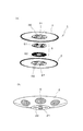
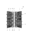
図1〜図3は、本発明のスタック構造体の一実施例を示しており、図1に示すように、このスタック構造体11は、集電体15を介して複数の固体電解質型燃料電池ユニット1を複数積層して成っている。
[Example 1]
1 to 3 show an embodiment of a stack structure according to the present invention. As shown in FIG. 1, the
このスタック構造体11を構成する固体電解質型燃料電池ユニット1は、図2(a)にも示すように、薄板を円錐状に形成して成っていると共に中心部分にガス導入孔21及びガス排出孔22を有する金属製セル板2と、円形薄板状を成し且つ中心部分にガス導入孔31及びガス排出孔32を有する金属製セパレータ板3を備えている。これらのセル板2及びセパレータ板3は、互いに対向した状態で各々の外周縁部同士を接合させてあり、セル板2及びセパレータ板3間に形成される空間には、内側集電体4が収容してある。
As shown in FIG. 2 (a), the solid oxide
セル板2の中心部分と外周縁部との間の円錐面領域には、図2(b)にも示すように、円形状を成す単セル6が複数個固定してあり、これらの単セル6は、電解質支持型セル、電極支持型セル、多孔質支持型セルのいずれでもあってもよい。
As shown in FIG. 2B, a plurality of circular
また、セル板2及びセパレータ板3の各中心部分間には、ガス導入孔21,31と連通して上記空間に燃料ガスを供給するガス導入流路51と、ガス排出孔22,32と連通して上記空間から燃料ガスを排出するガス排出流路52を具備した流路部品5が収容してあり、この流路部品5はユニット積層方向に二分割されていて、後述するように、固体電解質型燃料電池ユニット1を積層してスタック構造体11を形成した状態において、スタック構造体11全体の押付力のみで互いに密着するようになっている。
Further, between the central portions of the
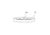
この場合、上記したように、セル板2を円錐状に形成することで、すなわち、セル板2を固体電解質型燃料電池ユニット1の積層方向と直交する方向に対して傾斜させることで、隣接する固体電解質型燃料電池ユニット1の各外周縁部の間隔が各中心部の間隔よりも大きくなるようにしており、これに伴って、図3に示すように、固体電解質型燃料電池ユニット1,1間に介在させる集電体15を断面が楔形を成すすり鉢状に形成してある。
In this case, as described above, the
つまり、セル板2を固体電解質型燃料電池ユニット1の積層方向と直交する方向に対して傾斜させると共に、集電体15を断面が楔形を成すすり鉢状に形成することによって、集電体15に対して固体電解質型燃料電池ユニット1の積層方向と直交する方向の力を付与することで、この集電体15をセル板2の単セル6に押し付けることができるようにしてある。この際、すり鉢状の集電体15の中央部分にスリット15aを設けることによって、ユニット積層方向と直交する方向の力が付与された時点における集電体15の変形を許容するようにしている。
That is, the
この実施例において、セル板2及びセパレータ板3には、肉厚が0.1mmのSUS430の圧延板を用いた。そして、この圧延板を超硬及びSKD11から成る金型を装備したプレス装置にセットして、80トンのプレス荷重をかけてプレス加工を行った。このプレス加工により得られた円錐状のセル板2及び円形状のセパレータ板3の各外径は120mmであり、セル板2及びセパレータ板3の各外周縁部同士を接合して、厚さ1.5mmの固体電解質型燃料電池ユニット1とした。
In this example, the
また、セル板2及びセパレータ板3間の空間に収容する内側集電体4には、インコネル製金属メッシュから成るものを用い、セル板2及びセパレータ板3に対してその周縁部をレーザ溶接により接合した。一方、外側の集電体15にもインコネル製金属メッシュから成るものを用い、断面が楔形を成すすり鉢状に形成して、固体電解質型燃料電池ユニット1の積層時にユニット1,1間に介在させるようにした。
The inner
さらに、流路部品5にもSUS430を用い、セル板2及びセパレータ板3に対しては、接合温度を1000℃以下とした真空中での拡散接合により固定し、接合時の変形を防いでいる。なお、拡散接合に代えてYAGレーザを用いたレーザ溶接による接合も可能であり、この際、セル板2及びセパレータ板3が薄板状を成していることから、表側からレーザを照射しても接合することができる。また、流路部品5の流路パターンは、エッチングや研削加工やレーザ加工により形成することができるほか、エッチング部品を積層して接合することによっても形成することができる。
Furthermore, SUS430 is also used for the
この実施例に係るスタック構造体11は、上記集電体15を介して固体電解質型燃料電池ユニット1を複数積層して成っていて、セル板2及びセパレータ板3の各ガス排出孔22,32に挿通した図示しない複数本のスタッドボルトを介して、互いに積層した固体電解質型燃料電池ユニット1同士を締結するようにしている。
The
そして、このスタック構造体11をガス導入部12a及びガス排出部12bを有するケース12内に収容することで、燃料電池10を構成するようにしており、この燃料電池10では、ガス導入部12aから導入した空気をスタック構造体11の互いに重なり合う固体電解質型燃料電池ユニット1の間の集電体15を通してガス排出部12bに流すことで発電するようになっている。
The
上記したスタック構造体11では、セル板2を固体電解質型燃料電池ユニット1の積層方向と直交する方向に対して傾斜させると共に、集電体15を断面が楔形を成すすり鉢状に形成しているので、この集電体15に固体電解質型燃料電池ユニット1の積層方向と直交する方向の力を付与するだけで、この集電体15をセル板2の単セル6に押し付け得ることとなる。
In the
つまり、固体電解質型燃料電池ユニット1を複数積層してスタック構造体11を組立てた後において、固体電解質型燃料電池ユニット1,1間に配置する集電体15にその積層方向と直交する方向の力を付与する作業を行えば、集電体15と単セル6とを確実に接触させ得ることから、互いに重なり合う固体電解質型燃料電池ユニット1,1間の密着性が高まることとなって、作製歩留り及び出力の向上が図られることとなり、この際、集電体15と単セル6とをろう材で接着する必要もないので、単セル6の性能低下を招くことも回避されることとなる。
That is, after the
また、上記したスタック構造体11では、セル板2を固体電解質型燃料電池ユニット1の積層方向と直交する方向に対して傾斜させることで、隣接する固体電解質型燃料電池ユニット1,1の各外周縁部の間隔よりも各中心部の間隔が漸次小さくなるようにしているので、固体電解質型燃料電池ユニット1の中心側空間が広くなって、中心部分のガスの導入孔21,31に対する単セル6の投影面積が広くなることから、単セル6の電極に対して多量のガスがスムーズに供給されることとなり、この場合、セル板2を傾斜させているので、固体電解質型燃料電池ユニット1の強度が向上することとなる。
Further, in the
上記した実施例では、スタック構造体11の固体電解質型燃料電池ユニット1,1間に配置する集電体15を断面が楔形を成すすり鉢状に形成した場合を示したが、図4に示すように、集電体15を断面が楔形を成すブロック状に形成して、セル板2の単セル6に合わせて配置するように成すことも可能である。
In the above-described embodiment, the case where the
また、上記した実施例のスタック構造体11の固体電解質型燃料電池1では、セル板2が円錐状を成し、且つ、セパレータ板3が円形状を成しているが、これに限定されるものではなく、例えば、図5(a)示すように、セパレータ板3が円形凸状段差部33を有する形状を成していてもよいほか、図5(b)示すように、単セル6を取り付けるセル板2が環状段差部24を有する形状を成していてもよい。
Moreover, in the solid
[実施例2]
図6は、本発明のスタック構造体の他の実施例を示しており、図6に示すように、この実施例によるスタック構造体11が、先の実施例のスタック構造体11と相違するところは、セパレータ板3を円錐状に形成することで、すなわち、セパレータ板3を固体電解質型燃料電池ユニット1の積層方向と直交する方向に対して傾斜させることで、隣接する固体電解質型燃料電池ユニット1の各外周縁部の間隔が各中心部の間隔よりも大きくなるようにし、これに伴って、固体電解質型燃料電池ユニット1,1間に介在させる集電体15を断面が楔形を成すすり鉢状に形成した点にあり、他の構成は先の実施例のスタック構造体11と同じである。
[Example 2]
FIG. 6 shows another embodiment of the stack structure of the present invention. As shown in FIG. 6, the
この実施例のスタック構造体11では、先の実施例のスタック構造体11と同様に、固体電解質型燃料電池ユニット1を複数積層してスタック構造体11を組立てた後において、固体電解質型燃料電池ユニット1,1間に配置する集電体15にその積層方向と直交する方向の力を付与する作業を行えば、集電体15と単セル6とを確実に接触させ得ることから、互いに重なり合う固体電解質型燃料電池ユニット1,1間の密着性が高まることとなって、作製歩留り及び出力の向上が図られることとなり、この際、集電体15と単セル6とをろう材で接着する必要もないので、単セル6の性能低下を招くことも回避されることとなる。
In the
また、このタック構造体11では、固体電解質型燃料電池ユニット1のセル板2を固体電解質型燃料電池ユニット1の積層方向と直交する方向に沿わせているので、後述するように、大型のドーナツ状単セル6Aを用い得ることとなり、すなわち、単セルの形状の自由度が広がり、単セルを搭載する板の加工難易度も低くなる。
Further, in this
[実施例3]
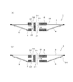
図7は、本発明のスタック構造体のさらに他の実施例を示しており、図7に部分的に示すように、この実施例によるスタック構造体11が、先の実施例のスタック構造体11と相違するところは、セル板2及びセパレータ板3をいずれも円錐状に形成することで、すなわち、セル板2及びセパレータ板3を固体電解質型燃料電池ユニット1の積層方向と直交する方向に対してそれぞれ傾斜させることで、隣接する固体電解質型燃料電池ユニット1の各外周縁部の間隔が各中心部の間隔よりも大きくなるようにした点にあり、他の構成は先の実施例のスタック構造体11と同じである。
[Example 3]
FIG. 7 shows still another embodiment of the stack structure of the present invention. As shown partially in FIG. 7, the
この実施例のスタック構造体11においても、その組立て後において、固体電解質型燃料電池ユニット1,1間に配置する集電体15(図7では省略)にその積層方向と直交する方向の力を付与する作業を行えば、集電体15と単セル6とを確実に接触させ得ることから、互いに重なり合う固体電解質型燃料電池ユニット1,1間の密着性が高まることとなって、作製歩留り及び出力の向上が図られることとなる。
Also in the
また、このタック構造体11では、固体電解質型燃料電池ユニット1のセル板2及びセパレータ板3をいずれも固体電解質型燃料電池ユニット1の積層方向と直交する方向に対して傾斜させているので、すなわち、セル板2及びセパレータ板3がいずれも円錐状となるので、固体電解質型燃料電池ユニット1の強度が向上することとなる。
Moreover, in this
[実施例4]
図8は、本発明のさらに他の実施例によるスタック構造体に採用する集電体を示している。図8に示すように、この実施例による集電体45は、通気性を有する導電性材料から成る集電体本体45aと、通気性を有し且つ集電体本体43aを隣接する固体電解質型燃料電池ユニット1(図8では省略)の双方に圧接させる楔形を成すスペーサ45bを具備しており、この集電体45において、通気孔を有するセラミックをスペーサ45bとして採用すれば、金属部品が減る分だけコストの低減が図られることとなる。
[Example 4]
FIG. 8 shows a current collector employed in a stack structure according to still another embodiment of the present invention. As shown in FIG. 8, a
[実施例5]
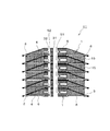
図9〜図11は、本発明のスタック構造体のさらに他の実施例を示しており、図9に示すように、この実施例によるスタック構造体11が、先の実施例のスタック構造体11と相違するところは、集電体15に固体電解質型燃料電池ユニット1の積層方向と直交する方向の力を付与して、該集電体15の隣接する固体電解質型燃料電池ユニット1,1の双方に対する圧接状態を維持する押圧保持手段としてのリング部材51を設けた点にあり、他の構成は先の実施例のスタック構造体11と同じである。
[Example 5]
9 to 11 show still another embodiment of the stack structure according to the present invention. As shown in FIG. 9, the
このリング部材51は、図10及び図11に示すように、絶縁体から成る二本の分割帯51a,51aを二つの連結部52,52を介して連結して成っており、固体電解質型燃料電池ユニット1,1間の集電体15のそれぞれに対して互いに独立して配置してある。この場合、連結部52に長さ調整機能を持たせることで、集電体15に対する押圧力を調整し得るようにしてある、すなわち、隣接する固体電解質型燃料電池ユニット1,1の双方に対する集電体15の圧接状態を調整し得るようにしてある。
As shown in FIGS. 10 and 11, the
この実施例のスタック構造体11では、その組立て後において、固体電解質型燃料電池ユニット1,1間の集電体15のそれぞれに沿うようにしてリング部材51を配置し、連結部52によりリング部材51の長さ調整を行って各固体電解質型燃料電池ユニット1,1間の集電体15にその積層方向と直交する方向の力を付与するように成せば、集電体15と単セル6とを確実に接触させ得ることから、互いに重なり合う固体電解質型燃料電池ユニット1,1間の密着性がより一層高まることとなって、作製歩留り及び出力の向上が図られることとなる。
In the
また、この実施例のスタック構造体11では、リング部材51を固体電解質型燃料電池ユニット1,1間のそれぞれに対して独立して配置するようにしているので、固体電解質型燃料電池ユニット1,1間の集電体15それぞれに対して荷重をかけ得ることとなって、効率的な出力向上が図られると共に、破損を阻止し得ることとなる。
Further, in the
この実施例では、リング部材51が、二本の分割帯51a,51aを二つの連結部52,52を介して連結して成るものとしているが、図12(a)に示すように、リング部材51を、一体物のリング部材51としてその両端部を一つの連結部52を介して連結するようにしてもよいほか、図12(b)に示すように、スタック構造体11を収容するケース12の内壁に形成した突起条51Aを押圧保持手段として機能させるようにしてもよい。
In this embodiment, the
[実施例6]
図13及び図14は、本発明のスタック構造体のさらに他の実施例を示しており、図13に示すように、この実施例によるスタック構造体11が、先の実施例のスタック構造体11と相違するところは、固体電解質型燃料電池ユニット1の外周縁部に装着された絶縁体から成る止め具61を押圧保持手段とした点にあり、他の構成は先の実施例のスタック構造体11と同じである。
[Example 6]
FIGS. 13 and 14 show still another embodiment of the stack structure of the present invention. As shown in FIG. 13, the
この押圧保持手段としての止め具61は、図14に示すように、固体電解質型燃料電池ユニット1の外周縁部において、セル板2の単セル6に合わせて配置してあって、この実施例では、固体電解質型燃料電池ユニット1の外周縁部に対してそのばね性を利用して装着してある。
As shown in FIG. 14, the
この実施例のスタック構造体11では、スタック構造体11の組立て後において、押圧保持手段としての止め具61を固体電解質型燃料電池ユニット1の外周縁部に装着することで、集電体15の部分的な押し付けを追加して行い得ることとなる。
In the
[実施例7]
図15及び図16は、本発明のスタック構造体のさらに他の実施例を示しており、図15に示すように、この実施例によるスタック構造体11が、先の実施例のスタック構造体11と相違するところは、複数の固体電解質型燃料電池ユニット1,1間に対して燃料ガス及び空気のうちの他方のガスを供給するべく配置するガス供給管71を押圧保持手段とした点にあり、他の構成は先の実施例のスタック構造体11と同じである。
[Example 7]
FIGS. 15 and 16 show still another embodiment of the stack structure of the present invention. As shown in FIG. 15, the
この押圧保持手段としてのガス供給管71は、固体電解質型燃料電池ユニット1,1間の集電体15のそれぞれに対して配置してあり、この場合、図16に示すように、ガス流入側の端部と閉塞端部同士を連結する連結部72に長さ調整機能を持たせることで、隣接する固体電解質型燃料電池ユニット1,1の双方に対する集電体15の圧接状態を調整し得るようにしてある。
The
この実施例のスタック構造体11においても、その組立て後に固体電解質型燃料電池ユニット1,1間のそれぞれに沿うようにしてガス供給管71を配置し、連結部72によりガス供給管71の長さ調整を行って各固体電解質型燃料電池ユニット1,1間の集電体15にその積層方向と直交する方向の力を付与するように成せば、集電体15と単セル6とを確実に接触させ得ることから、互いに重なり合う固体電解質型燃料電池ユニット1,1間の密着性がより一層高まることとなって、作製歩留り及び出力の向上が図られることとなる。
Also in the
[実施例8]
図17は、本発明のスタック構造体のさらに他の実施例を示しており、図17に示すように、この実施例によるスタック構造体11が、先の実施例のスタック構造体11と相違するところは、セル板2及びセパレータ板3をいずれも固体電解質型燃料電池ユニット1の積層方向と直交する方向に対して傾斜させることで、隣接する固体電解質型燃料電池ユニット1の各外周縁部の間隔が各中心部の間隔よりも小さくなるようにし、これに伴って、固体電解質型燃料電池ユニット1,1間に介在させる集電体15を断面が楔形を成す円盤状に形成した点にあり、他の構成は先の実施例のスタック構造体11と同じである。
[Example 8]
FIG. 17 shows still another embodiment of the stack structure of the present invention. As shown in FIG. 17, the
この実施例のスタック構造体11では、固体電解質型燃料電池ユニット1を複数積層してスタック構造体11を組立てた後において、隣接する固体電解質型燃料電池ユニット1,1間に配置した集電体15をその積層方向と直交する方向に引張る作業を行えば、集電体15と単セル6とを確実に接触させ得ることから、互いに重なり合う固体電解質型燃料電池ユニット1,1間の密着性が高まることとなって、作製歩留り及び出力の向上が図られることとなり、この際、固体電解質型燃料電池ユニット1の外周縁部側が広くなる分だけ、固体電解質型燃料電池ユニット1内への整流部品などの搬入が容易になる。
In the
[実施例9]
図18は、本発明のスタック構造体のさらに他の実施例を示しており、図18に示すように、この実施例によるスタック構造体11が、先の実施例のスタック構造体11と相違するところは、セル板2を固体電解質型燃料電池ユニット1の積層方向と直交する方向に対して傾斜させることで、隣接する固体電解質型燃料電池ユニット1の各外周縁部の間隔が各中心部の間隔よりも小さくなるようにした点にあり、他の構成は先の実施例のスタック構造体11と同じである。
[Example 9]
FIG. 18 shows still another embodiment of the stack structure of the present invention. As shown in FIG. 18, the
この実施例のスタック構造体11においても、その組立て後において、固体電解質型燃料電池ユニット1,1間に配置する集電体15(図18では省略)をその積層方向と直交する方向に引張る作業を行えば、集電体15と単セル6とを確実に接触させ得ることから、互いに重なり合う固体電解質型燃料電池ユニット1,1間の密着性が高まることとなって、作製歩留り及び出力の向上が図られることとなる。
Also in the
上記した各実施例では、単セル6が小径の円板状を成す場合を示したが、これに限定されるものではなく、例えば、図19(a)に示すように、単セル6Aがドーナツ状を成す場合には、その内周縁部及び外周縁部にプレス加工済の内側リング7及び外側リング8をそれぞれ接合してセル板2Aとすることができ、この際、接合時の作業性を考慮して、図19(b)に示すように、内側リング7及び外側リング8を縦横の桟9で連結してフレームを形成するようにしてもよく、このフレームに扇形の単セル6Bを取付けることも可能である。
In each of the above-described embodiments, the case where the
1 固体電解質型燃料電池ユニット
2 セル板
3 セパレータ板
6,6A,6B 単セル
10 燃料電池
11 スタック構造体
12 ケース
12a ガス導入部
12b ガス排出部
15,45 集電体
21,31 ガス導入孔
22,32 ガス排出孔
45a 集電体本体
45b スペーサ
51,51A リング部材(押圧保持手段)
52 調整部
61 止め具(押圧保持手段)
DESCRIPTION OF
52
Claims (14)
隣接する固体電解質型燃料電池ユニットの各外周縁部の間隔と各中心部の間隔とを変えるべく、固体電解質型燃料電池ユニットのセル板及びセパレータ板のうちの少なくともいずれか一方を固体電解質型燃料電池ユニットの積層方向と直交する方向に対して傾斜させ、隣接する固体電解質型燃料電池ユニットの双方に圧接可能な楔形に集電体を形成してあることを特徴とするスタック構造体。 A cell plate holding a single cell and having an introduction hole for one of the fuel gas and air in the central part, and an introduction hole for one of the fuel gas and air in the central part; and A current collector between the solid oxide fuel cell units, comprising a plurality of stacked solid oxide fuel cell units having a separator plate with its outer peripheral edge joined to the outer peripheral edge of the cell plate via a current collector. The current collector can be pressed against a single cell of the cell plate by applying a force in a direction perpendicular to the stacking direction of the solid oxide fuel cell unit ,
At least one of the cell plate and the separator plate of the solid oxide fuel cell unit is used as a solid electrolyte fuel so as to change the interval between the outer peripheral edge portions and the interval between the central portions of adjacent solid oxide fuel cell units. A stack structure characterized in that a current collector is formed in a wedge shape that is inclined with respect to a direction orthogonal to the stacking direction of the battery units and can be pressed against both adjacent solid oxide fuel cell units .
Priority Applications (1)
| Application Number | Priority Date | Filing Date | Title |
|---|---|---|---|
| JP2006237098A JP5083644B2 (en) | 2006-09-01 | 2006-09-01 | Stack structure and fuel cell |
Applications Claiming Priority (1)
| Application Number | Priority Date | Filing Date | Title |
|---|---|---|---|
| JP2006237098A JP5083644B2 (en) | 2006-09-01 | 2006-09-01 | Stack structure and fuel cell |
Publications (2)
| Publication Number | Publication Date |
|---|---|
| JP2008059957A JP2008059957A (en) | 2008-03-13 |
| JP5083644B2 true JP5083644B2 (en) | 2012-11-28 |
Family
ID=39242438
Family Applications (1)
| Application Number | Title | Priority Date | Filing Date |
|---|---|---|---|
| JP2006237098A Expired - Fee Related JP5083644B2 (en) | 2006-09-01 | 2006-09-01 | Stack structure and fuel cell |
Country Status (1)
| Country | Link |
|---|---|
| JP (1) | JP5083644B2 (en) |
Families Citing this family (2)
| Publication number | Priority date | Publication date | Assignee | Title |
|---|---|---|---|---|
| JP5751978B2 (en) * | 2011-08-02 | 2015-07-22 | 日本特殊陶業株式会社 | Fuel cell unit and fuel cell stack |
| JP6933039B2 (en) * | 2017-08-10 | 2021-09-08 | 日産自動車株式会社 | Fuel cell stack |
Family Cites Families (8)
| Publication number | Priority date | Publication date | Assignee | Title |
|---|---|---|---|---|
| FR2182650B1 (en) * | 1972-04-27 | 1974-07-26 | Citroen Sa | |
| JPH06196198A (en) * | 1992-12-24 | 1994-07-15 | Fuji Electric Co Ltd | Solid electrolyte type fuel cell |
| JPH06243879A (en) * | 1993-02-15 | 1994-09-02 | Fuji Electric Co Ltd | Solid electrolyte fuel cell |
| JP2004047155A (en) * | 2002-07-09 | 2004-02-12 | Honda Motor Co Ltd | Fuel cell |
| US20040219418A1 (en) * | 2003-04-30 | 2004-11-04 | Peter Mardilovich | Fuel cell assembly and method for controlling reaction equilibrium |
| JP2005353421A (en) * | 2004-06-10 | 2005-12-22 | Nissan Motor Co Ltd | Fuel cell |
| JP4501540B2 (en) * | 2004-06-11 | 2010-07-14 | 日産自動車株式会社 | Fuel cell |
| JP4507833B2 (en) * | 2004-11-02 | 2010-07-21 | トヨタ自動車株式会社 | Fuel cell and manufacturing method thereof |
-
2006
- 2006-09-01 JP JP2006237098A patent/JP5083644B2/en not_active Expired - Fee Related
Also Published As
| Publication number | Publication date |
|---|---|
| JP2008059957A (en) | 2008-03-13 |
Similar Documents
| Publication | Publication Date | Title |
|---|---|---|
| JP4848664B2 (en) | Solid oxide fuel cell and stack structure | |
| JP5365896B2 (en) | Fuel cell unit | |
| JP5679893B2 (en) | Solid oxide fuel cell and method for producing the same | |
| EP2586088B1 (en) | Fuel cell | |
| EP1942545B1 (en) | Fuel cell stack structure | |
| WO2006077762A1 (en) | Flat laminate type fuel cell and fuel cell stack | |
| JP5127389B2 (en) | Fuel cell and fuel cell stack | |
| JP5186124B2 (en) | Fuel cell separator | |
| JP5083644B2 (en) | Stack structure and fuel cell | |
| JP4123479B2 (en) | Single cell for fuel cell, method for producing the same, and solid oxide fuel cell | |
| JP5042588B2 (en) | Fuel cell | |
| JP5741943B2 (en) | Solid oxide fuel cell device | |
| JP2007141743A (en) | Current collector | |
| JP5267774B2 (en) | Fuel cell separator | |
| JP5046612B2 (en) | Fuel cell | |
| JP4848687B2 (en) | Fuel cell stack structure | |
| JP2017517837A (en) | Electrically insulating three-layer gasket for SFOC unit | |
| JP2009283146A (en) | Fuel cells | |
| EP3486986B1 (en) | Fuel cell stack | |
| JP4555174B2 (en) | Fuel cell and fuel cell stack | |
| JP4351617B2 (en) | Fuel cell | |
| TW201836207A (en) | Functionalized, porous gas conduction part for electrochemical module | |
| JP5049531B2 (en) | Fuel cell | |
| JP5722742B2 (en) | Fuel cell | |
| JP4963590B2 (en) | Fuel cell |
Legal Events
| Date | Code | Title | Description |
|---|---|---|---|
| A621 | Written request for application examination |
Free format text: JAPANESE INTERMEDIATE CODE: A621 Effective date: 20090330 |
|
| A977 | Report on retrieval |
Free format text: JAPANESE INTERMEDIATE CODE: A971007 Effective date: 20120229 |
|
| A131 | Notification of reasons for refusal |
Free format text: JAPANESE INTERMEDIATE CODE: A131 Effective date: 20120531 |
|
| A521 | Written amendment |
Free format text: JAPANESE INTERMEDIATE CODE: A523 Effective date: 20120726 |
|
| TRDD | Decision of grant or rejection written | ||
| A01 | Written decision to grant a patent or to grant a registration (utility model) |
Free format text: JAPANESE INTERMEDIATE CODE: A01 Effective date: 20120810 |
|
| A01 | Written decision to grant a patent or to grant a registration (utility model) |
Free format text: JAPANESE INTERMEDIATE CODE: A01 |
|
| A61 | First payment of annual fees (during grant procedure) |
Free format text: JAPANESE INTERMEDIATE CODE: A61 Effective date: 20120823 |
|
| R150 | Certificate of patent or registration of utility model |
Ref document number: 5083644 Country of ref document: JP Free format text: JAPANESE INTERMEDIATE CODE: R150 Free format text: JAPANESE INTERMEDIATE CODE: R150 |
|
| FPAY | Renewal fee payment (event date is renewal date of database) |
Free format text: PAYMENT UNTIL: 20150914 Year of fee payment: 3 |
|
| LAPS | Cancellation because of no payment of annual fees |