JP5083557B2 - Lens drive device - Google Patents
Lens drive device Download PDFInfo
- Publication number
- JP5083557B2 JP5083557B2 JP2008136289A JP2008136289A JP5083557B2 JP 5083557 B2 JP5083557 B2 JP 5083557B2 JP 2008136289 A JP2008136289 A JP 2008136289A JP 2008136289 A JP2008136289 A JP 2008136289A JP 5083557 B2 JP5083557 B2 JP 5083557B2
- Authority
- JP
- Japan
- Prior art keywords
- leaf spring
- lens
- pair
- driving device
- base
- Prior art date
- Legal status (The legal status is an assumption and is not a legal conclusion. Google has not performed a legal analysis and makes no representation as to the accuracy of the status listed.)
- Expired - Fee Related
Links
Images


Classifications
-
- G—PHYSICS
- G02—OPTICS
- G02B—OPTICAL ELEMENTS, SYSTEMS OR APPARATUS
- G02B7/00—Mountings, adjusting means, or light-tight connections, for optical elements
- G02B7/02—Mountings, adjusting means, or light-tight connections, for optical elements for lenses
- G02B7/04—Mountings, adjusting means, or light-tight connections, for optical elements for lenses with mechanism for focusing or varying magnification
- G02B7/08—Mountings, adjusting means, or light-tight connections, for optical elements for lenses with mechanism for focusing or varying magnification adapted to co-operate with a remote control mechanism
-
- H—ELECTRICITY
- H02—GENERATION; CONVERSION OR DISTRIBUTION OF ELECTRIC POWER
- H02K—DYNAMO-ELECTRIC MACHINES
- H02K41/00—Propulsion systems in which a rigid body is moved along a path due to dynamo-electric interaction between the body and a magnetic field travelling along the path
- H02K41/02—Linear motors; Sectional motors
- H02K41/035—DC motors; Unipolar motors
- H02K41/0352—Unipolar motors
- H02K41/0354—Lorentz force motors, e.g. voice coil motors
- H02K41/0356—Lorentz force motors, e.g. voice coil motors moving along a straight path
-
- H—ELECTRICITY
- H02—GENERATION; CONVERSION OR DISTRIBUTION OF ELECTRIC POWER
- H02K—DYNAMO-ELECTRIC MACHINES
- H02K5/00—Casings; Enclosures; Supports
- H02K5/04—Casings or enclosures characterised by the shape, form or construction thereof
- H02K5/22—Auxiliary parts of casings not covered by groups H02K5/06-H02K5/20, e.g. shaped to form connection boxes or terminal boxes
- H02K5/225—Terminal boxes or connection arrangements
-
- H—ELECTRICITY
- H04—ELECTRIC COMMUNICATION TECHNIQUE
- H04N—PICTORIAL COMMUNICATION, e.g. TELEVISION
- H04N23/00—Cameras or camera modules comprising electronic image sensors; Control thereof
- H04N23/50—Constructional details
- H04N23/54—Mounting of pick-up tubes, electronic image sensors, deviation or focusing coils
-
- H—ELECTRICITY
- H04—ELECTRIC COMMUNICATION TECHNIQUE
- H04N—PICTORIAL COMMUNICATION, e.g. TELEVISION
- H04N23/00—Cameras or camera modules comprising electronic image sensors; Control thereof
- H04N23/57—Mechanical or electrical details of cameras or camera modules specially adapted for being embedded in other devices
-
- H—ELECTRICITY
- H02—GENERATION; CONVERSION OR DISTRIBUTION OF ELECTRIC POWER
- H02K—DYNAMO-ELECTRIC MACHINES
- H02K2211/00—Specific aspects not provided for in the other groups of this subclass relating to measuring or protective devices or electric components
- H02K2211/03—Machines characterised by circuit boards, e.g. pcb
Landscapes
- Engineering & Computer Science (AREA)
- Physics & Mathematics (AREA)
- Multimedia (AREA)
- Signal Processing (AREA)
- Power Engineering (AREA)
- General Physics & Mathematics (AREA)
- Optics & Photonics (AREA)
- Chemical & Material Sciences (AREA)
- Combustion & Propulsion (AREA)
- Electromagnetism (AREA)
- Lens Barrels (AREA)
- Studio Devices (AREA)
Description
本発明はレンズ駆動装置に関し、特に、携帯型小型カメラに用いられるオートフォーカス用レンズ駆動装置に関する。 The present invention relates to a lens driving device, and more particularly to an autofocus lens driving device used for a portable small camera.
カメラ付携帯電話には携帯型小型カメラが搭載されている。この携帯型小型カメラには、オートフォーカス用レンズ駆動装置が用いられる。従来から、種々のオートフォーカス用レンズ駆動装置が提案されている。 A portable small camera is mounted on a camera-equipped mobile phone. This portable small camera uses an autofocus lens driving device. Conventionally, various autofocus lens driving devices have been proposed.
例えば、特許文献1(特開2006−258969号公報)は、オートフォーカスに要する時間を短縮したカメラ付携帯電話を開示している。この特許文献3に開示されたカメラ付携帯電話(レンズ駆動装置)は、一端にレンズ(レンズホルダ、レンズバレル)が取り付けられた筒状部を有するホルダ(レンズホルダ)と、このホルダ(レンズホルダ)にホルダの筒状部の周囲に位置するように固定された駆動コイルと、この駆動コイルと対向する永久磁石を備えたヨークと、ホルダ(レンズホルダ)の筒状部の光軸方向両側に設けられ、ホルダ(レンズホルダ)を径方向に位置決めした状態で光軸方向に変位可能に支持する一対の板バネとを備える。駆動コイルに通電することで、永久磁石の磁界と駆動コイルに流れる電流による磁界との相互作用によって、レンズ(レンズアセンブリ)を光軸方向に位置調整可能である。一対の板バネのうち、一方は上側板バネ(前側スプリング)と呼ばれ、他方は下側板バネ(後側スプリング)と呼ばれる。上側板バネ(前側スプリング)の内周側端部は、ホルダの上端(前端)とストッパとの間に挟持されて、ホルダ(レンズホルダ)に嵌合されている。 For example, Patent Document 1 (Japanese Patent Laid-Open No. 2006-258969) discloses a camera-equipped mobile phone in which the time required for autofocus is reduced. The camera-equipped mobile phone (lens driving device) disclosed in Patent Document 3 includes a holder (lens holder) having a cylindrical portion with a lens (lens holder, lens barrel) attached to one end, and the holder (lens holder). ) On the both sides in the optical axis direction of the cylindrical portion of the holder (lens holder), a drive coil fixed so as to be positioned around the cylindrical portion of the holder, a yoke having a permanent magnet facing the drive coil And a pair of leaf springs that support the holder (lens holder) so as to be displaceable in the optical axis direction while being positioned in the radial direction. By energizing the drive coil, the position of the lens (lens assembly) can be adjusted in the optical axis direction by the interaction between the magnetic field of the permanent magnet and the magnetic field generated by the current flowing in the drive coil. One of the pair of leaf springs is called an upper leaf spring (front spring), and the other is called a lower leaf spring (rear spring). The inner peripheral side end of the upper leaf spring (front spring) is sandwiched between the upper end (front end) of the holder and the stopper and is fitted to the holder (lens holder).
この特許文献1に開示されたレンズ駆動装置は、下側板バネの光軸方向外側に設けられ、下側板バネをヨークの光軸方向端面との間で挟持するアクチュエータ・ベースと、駆動コイルに電力を供給するために、下側板バネとアクチュエータ・ベースとの間に配置されたリート状電極(電力供給部材)とを更に有する。シート状電極は、ポリイミドのシート材から成る略円形リング状に形成したリング状部(電極部)と、このリング状部から径方向外側に延出する延出部とを有する。この延出部は、アクチュエータ・ベースの挿入孔を通じてアクチュエータ・ベースの外部に延出している。延出部は、モジュール基板に接続され、駆動コイルに電流を供給する役割を果たす。シート状電極のリング状部上に設けられた端子部に駆動コイルの一対の引出し線の先端をはんだ付けすることで、駆動コイルに電力を供給することができる。 The lens driving device disclosed in Patent Document 1 is provided on the outer side in the optical axis direction of the lower leaf spring, and sandwiches the lower leaf spring with the end surface in the optical axis direction of the yoke. In order to supply electric power, it further has a REIT electrode (power supply member) disposed between the lower leaf spring and the actuator base. The sheet-like electrode has a ring-shaped portion (electrode portion) formed in a substantially circular ring shape made of a polyimide sheet material, and an extending portion extending radially outward from the ring-shaped portion. The extending portion extends to the outside of the actuator base through the insertion hole of the actuator base. The extension part is connected to the module substrate and serves to supply a current to the drive coil. Electric power can be supplied to the drive coil by soldering the tips of the pair of lead wires of the drive coil to terminal portions provided on the ring-shaped portion of the sheet-like electrode.
前述した特許文献1に開示されたレンズ駆動装置では、シート状電極が可撓性を有するので、モジュール基板への導出をレンズ駆動装置の側面で行う必要がある。シート状電極が可撓性を有するので、シート状電極の延出部をモジュール基板にハンダ付けすることが困難である。また、シート状電極の延出部が、レンズ駆動装置の外形よりも外側にはみ出す危険性がある。 In the lens driving device disclosed in Patent Document 1 described above, since the sheet-like electrode has flexibility, it is necessary to perform derivation to the module substrate on the side surface of the lens driving device. Since the sheet electrode has flexibility, it is difficult to solder the extended portion of the sheet electrode to the module substrate. Further, there is a risk that the extending portion of the sheet-like electrode protrudes outside the outer shape of the lens driving device.
本発明の課題は、モジュール基板に容易にハンダ付けすることが可能な電力供給部材を備えたレンズ駆動装置を提供することにある。 The subject of this invention is providing the lens drive device provided with the electric power supply member which can be easily soldered to a module board.
本発明の他の課題は、レンズ駆動装置の外形よりも外側にはみ出すことがない電力供給部材を備えたレンズ駆動装置を提供することにある。 Another object of the present invention is to provide a lens driving device including a power supply member that does not protrude outside the outer shape of the lens driving device.
本発明の他の目的は、説明が進むにつれて明らかになるだろう。 Other objects of the invention will become apparent as the description proceeds.
本発明によれば、レンズアセンブリを保持するための筒状部(140)を有するレンズホルダ(14)と、このレンズホルダに筒状部の周囲に位置するように固定された駆動コイル(16)と、この駆動コイルと対向する永久磁石(18)を備えたヨーク(20)と、レンズホルダの筒状部の光軸(O)方向両側に設けられ、レンズホルダを径方向に位置決めした状態で光軸(O)方向に変位可能に支持する上側板バネ(22)および下側板バネ(24)とを備え、上側板バネ(22)及び下側板バネ(24)の各々は、レンズホルダ(14)に取り付けられた内周側端部(222;242)とヨーク(20)に取り付けられた外周側端部(224;244)とを有し、駆動コイル(16)に通電することで、永久磁石(18)の磁界と駆動コイル(16)に流れる電流による磁界との相互作用によって、レンズホルダ(14)を光軸(O)方向に位置調整可能なレンズ駆動装置(10)であって、このレンズ駆動装置(10)は、ヨーク(20)を装着すると共に、下側板バネ(24)の外周側端部(244)をヨーク(20)とで挟持するベース(12)と、下側板バネ(24)とベース(12)との間に配置されて、駆動コイル(16)に電力を供給する電力供給部材(32)とを更に備えたレンズ駆動装置(10)において、電力供給部材(32)は、下側板バネ(24)とベース(12)との間に挟まれて、駆動コイル(16)の一対の引出し線(162)と電気的に接続されるフレキシブルプリント基板(322)と、ベース(12)に収容されて、フレキシブルプリント基板(322)と接続され、モジュール基板まで下方に延出するばね性を持つ一対の板金端子(324)と、を有することを特徴とするレンズ駆動装置が得られる。 According to the present invention, the lens holder (14) having the cylindrical portion (140) for holding the lens assembly, and the drive coil (16) fixed to the lens holder so as to be positioned around the cylindrical portion. And a yoke (20) provided with a permanent magnet (18) opposed to the drive coil, and a cylindrical portion of the lens holder provided on both sides in the optical axis (O) direction, with the lens holder positioned in the radial direction. An upper leaf spring (22) and a lower leaf spring (24) supported so as to be displaceable in the direction of the optical axis (O) are provided, and each of the upper leaf spring (22) and the lower leaf spring (24) includes a lens holder (14). ) Attached to the inner peripheral side end portion (222; 242) and the outer peripheral side end portion (224; 244) attached to the yoke (20). Magnetic field and drive of magnet (18) The lens driving device (10) is capable of adjusting the position of the lens holder (14) in the direction of the optical axis (O) by the interaction with the magnetic field due to the current flowing through the lens (16). The lens driving device (10) The base (12) for mounting the yoke (20) and sandwiching the outer peripheral end (244) of the lower leaf spring (24) with the yoke (20), the lower leaf spring (24) and the base (12) In the lens driving device (10) further provided with a power supply member (32) for supplying power to the drive coil (16), the power supply member (32) includes a lower leaf spring (24). ) And the base (12) and are electrically connected to the pair of lead wires (162) of the drive coil (16) and the flexible printed circuit board (322) accommodated in the base (12). , flexible printed Is connected to the preparative substrate (322), the lens driving device is obtained which is characterized by having a pair of sheet metal terminals (324) having a spring property that extends down to the module substrate.
上記本発明によるレンズ駆動装置(10)において、一対の板金端子(324)の各々は、ベース(12)に収容されて、フレキシブルプリント基板(322)の電極(322a)と弾性接触する先端部(324−1a)を持つ弾性接触部(324−1)と、この弾性接触部からモジュール基板まで延出する棒状延出部(324−2)とを有してよく、ベース(12)は、一対の板金端子の弾性接触部を収容して保持する一対の凹部(12a)と、一対の板金端子の棒状延出部が挿通するための一対の挿通孔(122a)とを有してよい。弾性接触部(324−1)の先端部(324−1a)には金メッキが施され、弾性接触部の先端部と接触する、フレキシブルプリント基板(322)の電極(322a)には金メッキが施されていることが好ましい。 In the lens driving apparatus (10) according to the present invention, one each of the pair of metal plate terminals (324) is accommodated in the base (12), tip electrode (322a) and elastically contact the flexible printed circuit board (322) (324-1a) may have an elastic contact portion (324-1) and a rod-like extension portion (324-2) extending from the elastic contact portion to the module substrate, and the base (12) You may have a pair of recessed part (12a) which accommodates and hold | maintains the elastic contact part of a pair of sheet metal terminal, and a pair of insertion hole (122a) for the rod-shaped extension part of a pair of sheet metal terminal to penetrate. The tip (324-1a) of the elastic contact portion (324-1) is gold-plated, and the electrode (322a) of the flexible printed circuit board (322) that is in contact with the tip of the elastic contact portion is gold-plated. It is preferable.
尚、上記括弧内の参照符号は、理解を容易にするために付したものであり、一例に過ぎず、これらに限定されないのは勿論である。 The reference numerals in the parentheses are given for ease of understanding, and are merely examples, and of course are not limited thereto.
本発明では、駆動コイルに電力を供給する電力供給部材が、下側板バネとベースとの間に挟まれて、駆動コイルの一対の引出し線と電気的に接続されるフレキシブルプリント基板と、ベースに収容されて、フレキシブルプリント基板と接続され、モジュール基板まで下方に延出するばね性を持つ一対の板金端子とから構成されるので、電力供給部材をモジュール基板に容易にハンダ付けすることが可能で、電力供給部材がレンズ駆動装置の外形よりも外側にはみ出すことがない。 In the present invention, a power supply member for supplying power to the drive coil is sandwiched between the lower leaf spring and the base and electrically connected to the pair of lead wires of the drive coil, and the base is accommodated, is connected to the flexible printed circuit board, since it is Toka et configured pair of sheet metal end element having a spring property that extends down to the module substrate, it is possible to easily solder the power supply member to the module substrate Thus, the power supply member does not protrude outside the outer shape of the lens driving device.
以下、図面を参照して、本発明の実施の形態について説明する。 Embodiments of the present invention will be described below with reference to the drawings.
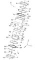
図1乃至図3を参照して、本発明の一実施の形態によるレンズ駆動装置10について説明する。図1はレンズ駆動装置10を示す斜視図であり、図2はレンズ駆動装置10の分解斜視図であり、図3はレンズ駆動装置10の主要部の正面断面図である。ここでは、図1乃至図3に示されるように、直交座標系(X,Y,Z)を使用している。図1乃至図3に図示した状態では、直交座標系(X,Y,Z)において、X軸は前後方向(奥行方向)であり、Y軸は左右方向(幅方向)であり、Z軸は上下方向(高さ方向)である。そして、図1乃至図3に示す例においては、上下方向Zがレンズの光軸O方向である。
A
但し、実際の使用状況においては、光軸O方向、すなわち、Z軸方向が前後方向となる。換言すれば、Z軸の上方向が前方向となり、Z軸の下方向が後方向となる。 However, in the actual use situation, the optical axis O direction, that is, the Z-axis direction is the front-rear direction. In other words, the upward direction of the Z axis is the forward direction, and the downward direction of the Z axis is the backward direction.
図示のレンズ駆動装置10は、オートフォーカス可能なカメラ付き携帯電話に備えられる。レンズ駆動装置10は、レンズアセンブリ(レンズバレル)(図示せず)を光軸O方向に移動させるためのものである。レンズ駆動装置10は、Z軸方向(光軸O方向)の下側(後側)に配置されたベース12を有する。このベース12の下部(後部)には、図示はしないが、モジュール基板に配置された撮像素子が搭載される。この撮像素子は、レンズアセンブリにより結像された被写体像を撮像して電気信号に変換する。撮像素子は、例えば、CCD(charge coupled device)型イメージセンサ、CMOS(complementary metal oxide semiconductor)型イメージセンサ等により構成される。したがって、レンズ駆動装置10と、モジュール基板と、撮像素子との組み合わせによって、カメラモジュールが構成される。
The illustrated
レンズ駆動装置10は、レンズアセンブリ(レンズバレル)を保持するための筒状部140を有するレンズホルダ14と、このレンズホルダ14に筒状部140の周囲に位置するように固定された駆動コイル16と、この駆動コイル16と対向する永久磁石18を備えたヨーク20と、レンズホルダ14の筒状部140の光軸O方向両側に設けられた一対の板バネ22、24を備える。一対の板バネ22、24は、レンズホルダ14を径方向に位置決めした状態で光軸O方向に変位可能に支持する。一対の板バネ22、24のうち、一方の板バネ22は上側板バネと呼ばれ、他方の板バネ24は下側板バネと呼ばれる。
The
また、前述したように、実際の使用状況においては、Z軸方向(光軸O方向)の上方向が前方向、Z軸方向(光軸O方向)の下方向が後方向となる。したがって、上側板バネ22は前側スプリングとも呼ばれ、下側板バネ24は後側スプリングとも呼ばれる。
Further, as described above, in an actual use situation, the upward direction in the Z-axis direction (optical axis O direction) is the forward direction, and the downward direction in the Z-axis direction (optical axis O direction) is the backward direction. Therefore, the
図2に示されるように、ヨーク20は四角筒状をしている。すなわち、ヨーク20は、四角筒形状の外筒部202と、この外筒部202の上端(前端)に設けられた四角形のリング状端部204とを有する。
As shown in FIG. 2, the
従って、駆動コイル16も、四角筒状のヨーク20の形状に合わせた、略四角筒状をしている。レンズホルダ14の筒状部140は、駆動コイル16の四隅に対応した位置で、半径方向外側へ突出する4つの接触部140−1を持つ。これら4つの接触部140−1に、駆動コイル16の四隅が接着される。すなわち、駆動コイル16は、筒状部140の4つの接触部140−1で接着されている。
Therefore, the
一方、永久磁石18は、ヨーク20の四隅に配置される断面三角形の4つの永久磁石片182と、駆動コイル16の対向する2面に対向する2つの断面矩形状永久磁石片184とから構成される。すなわち、永久磁石18は、ヨーク20の四角筒形状の外筒部202の四隅と2側辺に配置された、合計6個の永久磁石片182、184から成る。
On the other hand, the
ヨーク20の外筒部202の内周面に、駆動コイル16と間隔を置いて、永久磁石18が配置されている。
A
上側板バネ(前側スプリング)22はレンズホルダ14における光軸O方向上側(前側)に配置され、下側板バネ(後側スプリング)24はレンズホルダ14における光軸O方向下側(後側)に配置される。上側板バネ(前側スプリング)22と下側板バネ(後側スプリング)24とは、略同一構成をしている。
The upper leaf spring (front spring) 22 is disposed on the upper side (front side) of the
詳述すると、上側板バネ(前側スプリング)22は、レンズホルダ14に取り付けられた内周側端部222と、ヨーク20に取り付けられた外周側端部224とを有する。内周側端部222と外周側端部224との間には、3つの腕部が設けられている。各腕部は、内周側端部222と外周側端部224とを繋いでいる。
More specifically, the upper leaf spring (front spring) 22 has an inner
同様に、下側板バネ(後側スプリング)24は、レンズホルダ14に取り付けられた内周側端部242と、ヨーク20に取り付けられた外周側端部244とを有する。内周側端部242と外周側端部244とに間には、3つの腕部が設けられている。各腕部は、内周側端部242と外周側端部244とを繋いでいる。
Similarly, the lower leaf spring (rear spring) 24 has an inner
尚、内周側端部は内輪とも呼ばれ、外周側端部は外輪とも呼ばれる。 The inner peripheral end is also called an inner ring, and the outer peripheral end is also called an outer ring.
上側板バネ(前側スプリング)22の内周側端部222は、レンズホルダ14とストッパ26に挟持されて固定されている。換言すれば、ストッパ26は、上側板バネ(前側スプリング)22の内周側端部222を、レンズホルダ14との間で挟持するように、レンズホルダ14と嵌合する。一方、上側板バネ(前側スプリング)22の外周側端部224は、ヨーク20とカバー28との間に挟持され固定されている。尚、上側板バネ(前側スプリング)22の外周側端部224とカバー28との間には、リング状プレート34が配置されている。
An inner
ストッパ26には、次に述べるような機能がある。すなわち、ストッパ26は、上側板バネ(前側スプリング)22の内周側端部222をレンズホルダ14にバラツキなく高精度に密着させる機能を持つ。これにより、VCM(ボイス・コイル・モータ)特性のバラツキを改善できる。また、ストッパ26は、上側板バネ(前側スプリング)22の接着強度を向上させる機能をもつ。これにより、レンズ駆動装置10の耐衝撃性を向上させている。さらに、ストッパ26は、レンズ駆動装置10の落下衝撃の際の上側板バネ(前側スプリング)22の変形を防止する機能を持つ。これによっても、レンズ駆動装置10の耐衝撃性を向上させている。また、ストッパ26は、レンズ駆動装置10の機械的ストロークを決める機能を持つ。
The
一方、下側板バネ(後側スプリング)24の外周側端部244は、スペーサ30を介してヨーク20に固定されている。換言すれば、スペーサ30と下側板バネ(後側スプリング)24の外周側端部244とは、ヨーク20とベース12との間に挟持されて固定されている。下側板バネ(後側スプリング)24の内周側端部242は、レンズホルダ14の下端(後端)側に固定されている。
On the other hand, an outer
レンズホルダ14の筒状部140の内周壁には雌ネジ142が切られている。一方、図示しないが、レンズアセンブリ(レンズバレル)の外周壁には、上記雌ネジ142に螺合される雄ネジが切られている。従って、レンズアセンブリ(レンズバレル)をレンズホルダ14に装着するには、レンズアセンブリ(レンズバレル)をレンズホルダ14の筒状部140に対して光軸O周りに回転して光軸O方向に沿って螺合することにより、レンズアセンブリ(レンズバレル)をレンズホルダ14内に収容し、接着剤なとによって互いに接合する。
A
駆動コイル16に通電することで、永久磁石18の磁界と駆動コイル16に流れる電流による磁界との相互作用によって、レンズホルダ14(レンズアセンブリ)を光軸O方向に位置調整することが可能である。
By energizing the
下側板バネ(後側スプリング)24とベース12との間には、電力供給部材32が配置されている。この電力供給部材32は、駆動コイル16に電力を供給するためのものである。
A
電力供給部材32は、下側板バネ24とベース12との間に挟まれて、駆動コイル16の一対の引出し線162と電気的に接続されるフレキシブルプリント基板322と、このフレキシブルプリント基板322から上記モジュール基板まで下方に延出するばね性を持つ一対の板金端子324とを有する。
The
図3に示されるように、一対の板金端子324の各々は、ベース12に収容されて、フレキシブルプリント基板322の電極322aと弾性接触する先端部324−1aを持つ弾性接触部324−1と、この弾性接触部324−1からモジュール基板まで延出する棒状延出部324−2とを有する。ベース12は、一対の板金端子324の弾性接触部324−1を収容して保持する一対の凹部12aを有する。ベース12は、一対の板金端子324の棒状延出部324−2を挿通するための一対の挿通孔122aを持つガイド122を有する。
As shown in FIG. 3, each of the pair of
尚、弾性接触部324−1の先端部324−1aには金メッキが施され、弾性接触部324−1の先端部324−1aと接触する、フレキシブルプリント基板322の電極322aには金メッキが施されている。
The tip 322-1a of the elastic contact portion 324-1 is gold-plated, and the
このように、電力供給部材32は、下側板バネ24とベース12との間に挟まれて、駆動コイル16の一対の引出し線162と電気的に接続されるフレキシブルプリント基板322と、このフレキシブルプリント基板322からモジュール基板まで下方に延出するばね性を持つ一対の板金端子324とから構成されるので、電力供給部材32をモジュール基板に容易にハンダ付けで接続することが可能であり、電力供給部材32が、レンズ駆動装置10の外形よりも外側にはみ出すことがない。そして、ベース12として耐熱性が低いプリント基板を使用することが可能となる。
As described above, the
以上、本発明についてその好ましい実施の形態によって説明してきたが、本発明の精神を逸脱しない範囲内で、種々の変形が当業者によって可能であるのは明らかである。 Although the present invention has been described with reference to preferred embodiments, it is obvious that various modifications can be made by those skilled in the art without departing from the spirit of the present invention.
10 レンズ駆動装置
12 ベース
12a 凹部
122 ガイド
122a 挿通孔
14 レンズホルダ
140 筒状部
140−1 接触部
142 雌ネジ
16 駆動コイル
162 引出し線
18 永久磁石
182 断面三角形の永久磁石片
184 断面矩形状永久磁石片
20 ヨーク
202 外筒部
22 上側板バネ(前側スプリング)
222 内周側端部(内輪)
224 外周側端部(外輪)
24 下側板バネ(後側スプリング)
242 内周側端部(内輪)
244 外周側端部(外輪)
26 ストッパ
28 カバー
30 スペーサ
32 電力供給部材
322 フレキシブルプリント基板
322a 電極
324 板金端子
324−1 弾性接触部
324−1a 先端部
324−2 棒状延出部
34 リング状プレート
O 光軸
DESCRIPTION OF
222 Inner peripheral edge (inner ring)
224 Outer end (outer ring)
24 Lower leaf spring (rear spring)
242 Inner peripheral edge (inner ring)
244 Outer end (outer ring)
26
Claims (3)
前記電力供給部材は、
前記下側板バネと前記ベースとの間に挟まれて、前記駆動コイルの一対の引出し線と電気的に接続されるフレキシブルプリント基板と、
前記ベースに収容されて、前記フレキシブルプリント基板と接続され、モジュール基板まで下方に延出するばね性を持つ一対の板金端子と、
を有することを特徴とするレンズ駆動装置。 A lens holder having a cylindrical portion for holding a lens assembly, a drive coil fixed to the lens holder so as to be positioned around the cylindrical portion, and a yoke including a permanent magnet facing the drive coil And an upper leaf spring and a lower leaf spring that are provided on both sides of the cylindrical portion of the lens holder in the optical axis direction and support the lens holder so as to be displaceable in the optical axis direction in a state of being positioned in the radial direction, Each of the upper leaf spring and the lower leaf spring has an inner peripheral end attached to the lens holder and an outer peripheral end attached to the yoke, and by energizing the drive coil, A lens driving device capable of adjusting the position of the lens holder in the optical axis direction by an interaction between a magnetic field of a permanent magnet and a magnetic field generated by a current flowing in the driving coil, the lens driving device The yoke is mounted, and is disposed between a base that sandwiches the outer peripheral end of the lower leaf spring with the yoke, and between the lower leaf spring and the base, and supplies power to the drive coil. In the lens driving device further comprising a power supply member,
The power supply member is
A flexible printed circuit board sandwiched between the lower leaf spring and the base and electrically connected to a pair of lead wires of the drive coil;
A pair of sheet metal terminals housed in the base, connected to the flexible printed circuit board, and having a spring property extending downward to the module substrate ;
A lens driving device.
前記ベースは、前記一対の板金端子の前記弾性接触部を収容して保持する一対の凹部と、前記一対の板金端子の前記棒状延出部が挿通するための一対の挿通孔とを有する、
請求項1に記載のレンズ駆動装置。 Each of the pair of sheet metal terminals is housed in the base and has an elastic contact portion having a tip portion elastically contacting the electrode of the flexible printed circuit board, and a rod-like extension extending from the elastic contact portion to the module substrate. And
The base has a pair of recesses that receive and hold the elastic contact portions of the pair of sheet metal terminals, and a pair of insertion holes through which the rod-like extension portions of the pair of sheet metal terminals are inserted.
The lens driving device according to claim 1 .
当該弾性接触部の前記先端部と接触する、前記フレキシブルプリント基板の前記電極には金メッキが施されている、請求項2に記載のレンズ駆動装置。 The tip of the elastic contact portion is gold plated,
The lens driving device according to claim 2 , wherein the electrode of the flexible printed circuit board that is in contact with the tip of the elastic contact portion is plated with gold.
Priority Applications (4)
| Application Number | Priority Date | Filing Date | Title |
|---|---|---|---|
| JP2008136289A JP5083557B2 (en) | 2008-05-26 | 2008-05-26 | Lens drive device |
| TW098115132A TW200949409A (en) | 2008-05-26 | 2009-05-07 | Lens drive device |
| PCT/JP2009/059040 WO2009145072A1 (en) | 2008-05-26 | 2009-05-15 | Lens drive device |
| CN200980119061.7A CN102047164B (en) | 2008-05-26 | 2009-05-15 | Lens drive device |
Applications Claiming Priority (1)
| Application Number | Priority Date | Filing Date | Title |
|---|---|---|---|
| JP2008136289A JP5083557B2 (en) | 2008-05-26 | 2008-05-26 | Lens drive device |
Publications (3)
| Publication Number | Publication Date |
|---|---|
| JP2009282421A JP2009282421A (en) | 2009-12-03 |
| JP2009282421A5 JP2009282421A5 (en) | 2011-06-16 |
| JP5083557B2 true JP5083557B2 (en) | 2012-11-28 |
Family
ID=41376953
Family Applications (1)
| Application Number | Title | Priority Date | Filing Date |
|---|---|---|---|
| JP2008136289A Expired - Fee Related JP5083557B2 (en) | 2008-05-26 | 2008-05-26 | Lens drive device |
Country Status (4)
| Country | Link |
|---|---|
| JP (1) | JP5083557B2 (en) |
| CN (1) | CN102047164B (en) |
| TW (1) | TW200949409A (en) |
| WO (1) | WO2009145072A1 (en) |
Families Citing this family (14)
| Publication number | Priority date | Publication date | Assignee | Title |
|---|---|---|---|---|
| DE102009045223A1 (en) * | 2009-09-30 | 2011-03-31 | Carl Zeiss Smt Gmbh | Optical arrangement in a projection exposure machine for EUV lithography |
| JP5821356B2 (en) * | 2011-07-15 | 2015-11-24 | ミツミ電機株式会社 | Lens drive device |
| KR101343197B1 (en) * | 2012-09-07 | 2013-12-19 | 삼성전기주식회사 | Camera module |
| WO2014103457A1 (en) * | 2012-12-26 | 2014-07-03 | シャープ株式会社 | Lens drive apparatus |
| EP4194917A1 (en) * | 2014-01-02 | 2023-06-14 | Lg Innotek Co., Ltd. | Lens driving device and camera module comprising same |
| JP2016038505A (en) * | 2014-08-08 | 2016-03-22 | 惠州市大亜湾永昶電子工業有限公司 | Lens drive device |
| CN112363294B (en) | 2015-02-04 | 2022-10-11 | Lg伊诺特有限公司 | Lens driving device and camera module including the same |
| TWI579630B (en) * | 2015-11-20 | 2017-04-21 | 台灣東電化股份有限公司 | Lens driving module |
| CN105467551A (en) * | 2015-12-26 | 2016-04-06 | 上海比路电子有限公司 | Integrated base used in optical zooming motor and application technology of same |
| CN106772902B (en) * | 2017-01-10 | 2023-03-31 | 惠州萨至德光电科技有限公司 | Lens driving device |
| CN110873942B (en) * | 2018-09-03 | 2024-07-16 | 新思考电机有限公司 | Lens driving device, camera device and electronic apparatus |
| KR102262571B1 (en) * | 2019-04-17 | 2021-06-09 | 엘지이노텍 주식회사 | Voice coil motor |
| KR102109774B1 (en) * | 2019-04-17 | 2020-05-12 | 엘지이노텍 주식회사 | Voice coil motor |
| KR102384414B1 (en) * | 2020-05-06 | 2022-04-08 | 엘지이노텍 주식회사 | Voice coil motor |
Family Cites Families (7)
| Publication number | Priority date | Publication date | Assignee | Title |
|---|---|---|---|---|
| JP2003207708A (en) * | 2002-01-11 | 2003-07-25 | Shicoh Eng Co Ltd | Lens driving unit |
| JP4319950B2 (en) * | 2004-06-18 | 2009-08-26 | 日本電信電話株式会社 | Wavelength converter arrangement design method and apparatus |
| JP4617759B2 (en) * | 2004-07-30 | 2011-01-26 | ミツミ電機株式会社 | Autofocus actuator |
| JP3916628B2 (en) * | 2004-08-31 | 2007-05-16 | 三菱電機株式会社 | LENS DRIVE DEVICE AND IMAGING DEVICE |
| JP4696790B2 (en) * | 2005-08-31 | 2011-06-08 | ミツミ電機株式会社 | Camera actuator |
| JP4686739B2 (en) * | 2006-05-09 | 2011-05-25 | シコー株式会社 | Lens drive device |
| JP4725467B2 (en) * | 2006-09-14 | 2011-07-13 | ミツミ電機株式会社 | The camera module |
-
2008
- 2008-05-26 JP JP2008136289A patent/JP5083557B2/en not_active Expired - Fee Related
-
2009
- 2009-05-07 TW TW098115132A patent/TW200949409A/en unknown
- 2009-05-15 CN CN200980119061.7A patent/CN102047164B/en not_active Expired - Fee Related
- 2009-05-15 WO PCT/JP2009/059040 patent/WO2009145072A1/en active Application Filing
Also Published As
| Publication number | Publication date |
|---|---|
| WO2009145072A1 (en) | 2009-12-03 |
| TW200949409A (en) | 2009-12-01 |
| JP2009282421A (en) | 2009-12-03 |
| CN102047164A (en) | 2011-05-04 |
| CN102047164B (en) | 2013-05-15 |
Similar Documents
| Publication | Publication Date | Title |
|---|---|---|
| JP5083557B2 (en) | Lens drive device | |
| JP5071680B2 (en) | Lens drive device | |
| CN114839823B (en) | Lens moving device | |
| KR101044668B1 (en) | Lens driver and camera module | |
| US8982221B2 (en) | Photography device with a shake-correction structure | |
| JP5333790B2 (en) | Lens drive device | |
| JP5996672B2 (en) | Lens drive device | |
| JP4696790B2 (en) | Camera actuator | |
| US20190041662A1 (en) | Optical image stabilization mechanism | |
| TWI595301B (en) | Camera module and camera | |
| KR101172502B1 (en) | Lens actuator and camera module having the same | |
| US9341809B2 (en) | Lens focusing device | |
| KR20080105396A (en) | Voice coil module | |
| JP5252235B2 (en) | The camera module | |
| EP3115821A1 (en) | Miniature lens-driving apparatus | |
| JP2016020992A (en) | Lens drive device | |
| JP3916628B2 (en) | LENS DRIVE DEVICE AND IMAGING DEVICE | |
| US20220206247A1 (en) | Lens driving device, camera device and electronic apparatus | |
| US20220206365A1 (en) | Lens Driving Device, Camera Device and Electronic Apparatus | |
| KR20100008529A (en) | Camera module having mems actuator | |
| JP4527051B2 (en) | LENS DRIVE DEVICE AND IMAGING DEVICE | |
| JP2013222053A (en) | Camera module driving mechanism | |
| KR20170053274A (en) | Camera module | |
| EP2096477A1 (en) | Lens driving apparatus and camera module | |
| KR102357305B1 (en) | Lens driving unit and camera module including the same |
Legal Events
| Date | Code | Title | Description |
|---|---|---|---|
| A521 | Request for written amendment filed |
Free format text: JAPANESE INTERMEDIATE CODE: A523 Effective date: 20110426 |
|
| A621 | Written request for application examination |
Free format text: JAPANESE INTERMEDIATE CODE: A621 Effective date: 20110516 |
|
| A131 | Notification of reasons for refusal |
Free format text: JAPANESE INTERMEDIATE CODE: A131 Effective date: 20120606 |
|
| A521 | Request for written amendment filed |
Free format text: JAPANESE INTERMEDIATE CODE: A523 Effective date: 20120719 |
|
| TRDD | Decision of grant or rejection written | ||
| A01 | Written decision to grant a patent or to grant a registration (utility model) |
Free format text: JAPANESE INTERMEDIATE CODE: A01 Effective date: 20120808 |
|
| A01 | Written decision to grant a patent or to grant a registration (utility model) |
Free format text: JAPANESE INTERMEDIATE CODE: A01 |
|
| A61 | First payment of annual fees (during grant procedure) |
Free format text: JAPANESE INTERMEDIATE CODE: A61 Effective date: 20120821 |
|
| R150 | Certificate of patent or registration of utility model |
Ref document number: 5083557 Country of ref document: JP Free format text: JAPANESE INTERMEDIATE CODE: R150 Free format text: JAPANESE INTERMEDIATE CODE: R150 |
|
| FPAY | Renewal fee payment (event date is renewal date of database) |
Free format text: PAYMENT UNTIL: 20150914 Year of fee payment: 3 |
|
| LAPS | Cancellation because of no payment of annual fees |