JP5082011B2 - Battery power supply and battery power supply system - Google Patents
Battery power supply and battery power supply system Download PDFInfo
- Publication number
- JP5082011B2 JP5082011B2 JP2011510601A JP2011510601A JP5082011B2 JP 5082011 B2 JP5082011 B2 JP 5082011B2 JP 2011510601 A JP2011510601 A JP 2011510601A JP 2011510601 A JP2011510601 A JP 2011510601A JP 5082011 B2 JP5082011 B2 JP 5082011B2
- Authority
- JP
- Japan
- Prior art keywords
- current
- battery
- effective
- value
- individual
- Prior art date
- Legal status (The legal status is an assumption and is not a legal conclusion. Google has not performed a legal analysis and makes no representation as to the accuracy of the status listed.)
- Expired - Fee Related
Links
Images


Classifications
-
- H—ELECTRICITY
- H01—ELECTRIC ELEMENTS
- H01M—PROCESSES OR MEANS, e.g. BATTERIES, FOR THE DIRECT CONVERSION OF CHEMICAL ENERGY INTO ELECTRICAL ENERGY
- H01M10/00—Secondary cells; Manufacture thereof
- H01M10/42—Methods or arrangements for servicing or maintenance of secondary cells or secondary half-cells
- H01M10/44—Methods for charging or discharging
- H01M10/441—Methods for charging or discharging for several batteries or cells simultaneously or sequentially
-
- H—ELECTRICITY
- H02—GENERATION; CONVERSION OR DISTRIBUTION OF ELECTRIC POWER
- H02J—ELECTRIC POWER NETWORKS; CIRCUIT ARRANGEMENTS OR SYSTEMS FOR SUPPLYING OR DISTRIBUTING ELECTRIC POWER; SYSTEMS FOR STORING ELECTRIC ENERGY
- H02J7/00—Circuit arrangements for charging or discharging batteries or for supplying loads from batteries
- H02J7/50—Circuit arrangements for charging or discharging batteries or for supplying loads from batteries acting upon multiple batteries simultaneously or sequentially
-
- H—ELECTRICITY
- H02—GENERATION; CONVERSION OR DISTRIBUTION OF ELECTRIC POWER
- H02J—ELECTRIC POWER NETWORKS; CIRCUIT ARRANGEMENTS OR SYSTEMS FOR SUPPLYING OR DISTRIBUTING ELECTRIC POWER; SYSTEMS FOR STORING ELECTRIC ENERGY
- H02J7/00—Circuit arrangements for charging or discharging batteries or for supplying loads from batteries
- H02J7/80—Circuit arrangements for charging or discharging batteries or for supplying loads from batteries including monitoring or indicating arrangements
- H02J7/82—Control of state of charge [SOC]
-
- H—ELECTRICITY
- H02—GENERATION; CONVERSION OR DISTRIBUTION OF ELECTRIC POWER
- H02J—ELECTRIC POWER NETWORKS; CIRCUIT ARRANGEMENTS OR SYSTEMS FOR SUPPLYING OR DISTRIBUTING ELECTRIC POWER; SYSTEMS FOR STORING ELECTRIC ENERGY
- H02J7/00—Circuit arrangements for charging or discharging batteries or for supplying loads from batteries
- H02J7/80—Circuit arrangements for charging or discharging batteries or for supplying loads from batteries including monitoring or indicating arrangements
- H02J7/84—Control of state of health [SOH]
-
- Y—GENERAL TAGGING OF NEW TECHNOLOGICAL DEVELOPMENTS; GENERAL TAGGING OF CROSS-SECTIONAL TECHNOLOGIES SPANNING OVER SEVERAL SECTIONS OF THE IPC; TECHNICAL SUBJECTS COVERED BY FORMER USPC CROSS-REFERENCE ART COLLECTIONS [XRACs] AND DIGESTS
- Y02—TECHNOLOGIES OR APPLICATIONS FOR MITIGATION OR ADAPTATION AGAINST CLIMATE CHANGE
- Y02E—REDUCTION OF GREENHOUSE GAS [GHG] EMISSIONS, RELATED TO ENERGY GENERATION, TRANSMISSION OR DISTRIBUTION
- Y02E60/00—Enabling technologies; Technologies with a potential or indirect contribution to GHG emissions mitigation
- Y02E60/10—Energy storage using batteries
-
- Y—GENERAL TAGGING OF NEW TECHNOLOGICAL DEVELOPMENTS; GENERAL TAGGING OF CROSS-SECTIONAL TECHNOLOGIES SPANNING OVER SEVERAL SECTIONS OF THE IPC; TECHNICAL SUBJECTS COVERED BY FORMER USPC CROSS-REFERENCE ART COLLECTIONS [XRACs] AND DIGESTS
- Y02—TECHNOLOGIES OR APPLICATIONS FOR MITIGATION OR ADAPTATION AGAINST CLIMATE CHANGE
- Y02T—CLIMATE CHANGE MITIGATION TECHNOLOGIES RELATED TO TRANSPORTATION
- Y02T10/00—Road transport of goods or passengers
- Y02T10/60—Other road transportation technologies with climate change mitigation effect
- Y02T10/70—Energy storage systems for electromobility, e.g. batteries
Landscapes
- Engineering & Computer Science (AREA)
- Manufacturing & Machinery (AREA)
- Chemical & Material Sciences (AREA)
- Chemical Kinetics & Catalysis (AREA)
- Electrochemistry (AREA)
- General Chemical & Material Sciences (AREA)
- Power Engineering (AREA)
- Secondary Cells (AREA)
- Charge And Discharge Circuits For Batteries Or The Like (AREA)
- Battery Mounting, Suspending (AREA)
- Connection Of Batteries Or Terminals (AREA)
Description
本発明は、複数の二次電池が並列接続された電池ブロックを備える電池電源装置、及びこれを用いる電池電源システムに関する。 The present invention relates to a battery power supply device including a battery block in which a plurality of secondary batteries are connected in parallel, and a battery power supply system using the same.
従来より、二次電池を用いて負荷回路へ電力を供給する電池電源装置においては、負荷回路が必要とする出力電流量を確保する必要から、複数の二次電池を並列接続した電池ブロックが広く用いられている。 2. Description of the Related Art Conventionally, in battery power supply devices that use a secondary battery to supply power to a load circuit, there is a wide range of battery blocks in which a plurality of secondary batteries are connected in parallel because the amount of output current required by the load circuit is required. It is used.
このような電池電源装置においては、電池ブロックに含まれる一部の二次電池に過電流や過熱等の異常が生じた場合、正常時と同じようにこのような電池ブロックに対して充放電を行うと、二次電池を劣化させてしまうおそれがあった。 In such a battery power supply device, when an abnormality such as overcurrent or overheating occurs in some of the secondary batteries included in the battery block, the battery block is charged / discharged in the same manner as normal. If done, the secondary battery may be deteriorated.
そこで、電池ブロックに含まれる一部の二次電池の異常、例えば脱落や断線等の異常を検出し、このような異常が生じた場合にスイッチング素子や保護素子をオフさせて、電池電源装置全体の充放電を禁止する技術が知られている(例えば、特許文献1、2参照。)。
Therefore, the abnormality of some secondary batteries included in the battery block, such as an abnormality such as dropout or disconnection, is detected, and when such an abnormality occurs, the switching element and the protection element are turned off, and the entire battery power supply device A technique for prohibiting charging / discharging is known (for example, see
しかしながら、上述の技術のように、電池ブロックに含まれる一部の二次電池に異常が生じた場合に電池電源装置全体の充放電を禁止してしまうことが、好ましくない場合がある。 However, it may not be preferable to prohibit charging / discharging of the entire battery power supply apparatus when an abnormality occurs in some of the secondary batteries included in the battery block as in the above-described technique.
例えば、エンジンとモータとを用いたハイブリット自動車(HEV ; Hybrid Electric Vehicle)では、モータにより走行する場合には、電池電源装置からの放電電流によってモータを駆動し、電池ブロックを放電させる。一方、HEVの走行に必要な動力に対してエンジンからの出力が大きい場合には、HEVは、余剰のエンジン出力で発電機を駆動して電池電源装置の電池ブロックを充電する。また、HEVは、車両の制動や減速時には、モータを発電機として利用し、その回生電力によって電池電源装置の電池ブロックを充電する。 For example, in a hybrid vehicle (HEV: Hybrid Electric Vehicle) using an engine and a motor, when the vehicle is driven by a motor, the motor is driven by the discharge current from the battery power supply device to discharge the battery block. On the other hand, when the output from the engine is larger than the motive power required for running the HEV, the HEV drives the generator with the surplus engine output to charge the battery block of the battery power supply device. Further, the HEV uses a motor as a generator when the vehicle is braked or decelerated, and charges the battery block of the battery power supply device with the regenerative power.
従って、電池電源装置がHEVのような用途に用いられる場合には、電池ブロックに含まれる一部の二次電池に異常が生じた場合に電池電源装置の充放電を禁止してしまうと、走行中の車両が停車してしまったり、発電機で発電された電力や回生電力を電池電源装置で吸収することが出来なくなって過電圧が生じてしまったりするおそれがある。 Therefore, when the battery power supply device is used for an application such as HEV, if charging / discharging of the battery power supply device is prohibited when an abnormality occurs in some of the secondary batteries included in the battery block, driving There is a possibility that the vehicle inside stops, or that the power generated by the generator or the regenerative power cannot be absorbed by the battery power supply device and an overvoltage is generated.
本発明の目的は、電池ブロックに含まれる一部の二次電池に異常が生じた場合であっても、電池電源装置全体の充放電を禁止することなく、二次電池が劣化するおそれを低減することが容易な電池電源装置、及びこれを用いる電池電源システムを提供することである。 The object of the present invention is to reduce the possibility of deterioration of secondary batteries without prohibiting charging / discharging of the entire battery power supply device even when some secondary batteries included in the battery block are abnormal. It is an object of the present invention to provide a battery power supply device that can be easily performed and a battery power supply system using the same.
本発明の一局面に従う電池電源装置は、二次電池と当該二次電池の充放電経路を遮断する遮断状態となり得る遮断素子との直列回路が複数並列に接続された電池ブロックと、前記電池ブロックに流れる電流の電流値である全体電流値の許容値の上限を示す電流制限値を設定する電流制限値設定部と、前記電池ブロックに含まれる複数の前記遮断素子のうち、前記遮断状態ではない遮断素子の数を、有効電池数として検出する有効電池数検出部とを備え、前記電流制限値設定部は、前記有効電池数検出部によって検出された有効電池数が減少するほど前記電流制限値が小さくなるように、前記電流制限値を設定する。 A battery power supply device according to one aspect of the present invention includes a battery block in which a plurality of series circuits of a secondary battery and a blocking element that can be in a blocking state that blocks a charge / discharge path of the secondary battery are connected in parallel, and the battery block A current limit value setting unit that sets a current limit value that indicates an upper limit of an allowable value of the entire current value that is a current value of a current flowing through the battery block, and is not in the cut-off state among the plurality of cut-off elements included in the battery block An effective battery number detection unit that detects the number of blocking elements as the number of effective batteries, and the current limit value setting unit reduces the current limit value as the number of effective batteries detected by the effective battery number detection unit decreases. The current limit value is set so that becomes smaller.
また、本発明の一局面に従う電池電源システムは、上述の電池電源装置と、前記電池電源装置を充放電する外部装置をと備え、前記外部装置は、前記電池ブロックからの放電電流の供給を受け付ける負荷回路と、前記電池ブロックへ充電電流を供給する電流供給部と、前記電池ブロックに流れる電流が、前記電流制御部から送信された前記電流制限値を超えないように、前記電池ブロックから前記負荷回路へ供給される放電電流、及び前記電流供給部から前記電池ブロックへ供給される充電電流を調節する充放電制御部とを備える。 A battery power supply system according to one aspect of the present invention includes the battery power supply device described above and an external device that charges and discharges the battery power supply device, and the external device accepts supply of a discharge current from the battery block. A load circuit; a current supply unit that supplies a charging current to the battery block; and a current that flows through the battery block from the battery block so as not to exceed the current limit value transmitted from the current control unit. A charge / discharge control unit that adjusts a discharge current supplied to the circuit and a charge current supplied from the current supply unit to the battery block.
このような構成の電池電源装置、及びこれを用いる電池電源システムは、複数並列に接続された二次電池のそれぞれに、充放電経路を遮断するための遮断素子が直列接続されているので、電池ブロックに含まれる一部の二次電池に異常が生じた場合、当該異常が生じた一部の二次電池のみ、遮断素子によって充放電経路を遮断することができる結果、電池電源装置そのものの充放電を禁止することなく、異常が生じた一部の二次電池が劣化するおそれを低減することができる。 In the battery power supply device having such a configuration, and the battery power supply system using the same, a plurality of secondary batteries connected in parallel are connected in series with a blocking element for blocking the charging / discharging path. When an abnormality occurs in some secondary batteries included in the block, only a part of the secondary batteries in which the abnormality has occurred can interrupt the charge / discharge path by the blocking element. Without prohibiting discharge, it is possible to reduce the possibility of deterioration of some secondary batteries in which an abnormality has occurred.
さらに、有効電池数検出部によって、電池ブロック一つに含まれる複数の遮断素子のうち、遮断していない遮断素子の数が、有効電池数として検出され、電流制限値設定部によって、有効電池数が減少するほど電流制限値が小さくなるように、当該電流制限値が設定される。これにより、一部の遮断素子が遮断した場合、有効電池数が減少して電流制限値が小さくされるので、この電流制限値に基づき電池電源装置の充放電を行うことで、遮断されていない残りの二次電池に流れる電流が減少される結果、遮断されていない残りの二次電池が劣化するおそれが低減することが容易となる。 Further, the effective battery number detection unit detects the number of non-blocking blocking elements among the plurality of blocking elements included in one battery block as the number of effective batteries, and the current limit value setting unit detects the number of effective batteries. The current limit value is set so that the current limit value decreases as the current decreases. As a result, when some of the blocking elements are blocked, the number of effective batteries is reduced and the current limit value is reduced. Therefore, the battery power supply device is charged / discharged based on the current limit value, and is not blocked. As a result of the reduction of the current flowing through the remaining secondary batteries, it is easy to reduce the risk of deterioration of the remaining secondary batteries that are not cut off.
以下、本発明に係る実施形態を図面に基づいて説明する。なお、各図において同一の符号を付した構成は、同一の構成であることを示し、その説明を省略する。 Embodiments according to the present invention will be described below with reference to the drawings. In addition, the structure which attached | subjected the same code | symbol in each figure shows that it is the same structure, The description is abbreviate | omitted.
(第1実施形態)
図1は、本発明の第1施形態に係る電池電源装置を備えた電池電源システムの一例を示すブロック図である。
(First embodiment)
FIG. 1 is a block diagram showing an example of a battery power supply system including a battery power supply device according to the first embodiment of the present invention.
図1に示す電池電源システム3は、電池電源装置1と、外部装置2とが組み合わされて構成されている。図1に示す電池電源装置1は、m個(例えば10個)の電池ブロックBB1〜BBmと、全体電流検出部AAと、制御部10と、通信部11と、接続端子15,16,17とを備えている。
A battery
m個の電池ブロックBB1〜BBmは、直列接続されている。電池ブロックBB1〜BBmの直列回路における正極が、全体電流検出部AAを介して接続端子15に接続されている。また、電池ブロックBB1〜BBmの直列回路における負極が接続端子16に接続されている。また、接続端子17は、通信部11に接続されている。
The m battery blocks BB1 to BBm are connected in series. The positive electrode in the series circuit of the battery blocks BB1 to BBm is connected to the
なお、電池ブロックBB1〜BBmは、図1では一本の導線で接続されているが、複数本の導線で接続されていてもよい。 In addition, although battery block BB1-BBm is connected by one conducting wire in FIG. 1, you may be connected by several conducting wire.
図1に示す外部装置2は、充放電制御部21、発電装置22(電流供給部)、負荷装置23(負荷回路)、通信部24、及び接続端子25,26,27を備えている。そして、接続端子25,26が、充放電制御部21と接続され、接続端子27が、通信部24を介して充放電制御部21と接続されている。また、発電装置22と負荷装置23とは、充放電制御部21と接続されている。
The
そして、電池電源装置1と、外部装置2とが組み合わされると、接続端子15,16,17と接続端子25,26,27とがそれぞれ接続されるようになっている。
When the battery
電池ブロックBB1〜BBmは、同様に構成されているので、電池ブロックBB1〜BBmを代表してi番目の電池ブロックBBiについて、その構成を説明する。 Since the battery blocks BB1 to BBm are configured in the same manner, the configuration of the i-th battery block BBi will be described on behalf of the battery blocks BB1 to BBm.
電池ブロックBBiは、遮断素子の一例であるヒューズFと二次電池Bとの直列回路がn個(例えば50個)並列接続されて構成されている。以下、図1に記載の電池ブロックBBiにおいて、各直列回路に含まれるヒューズF、及び二次電池Bを、図中左から順に付した番号jによって、ヒューズFi−j、二次電池Bi−jと表記する。 The battery block BBi is configured by connecting n (for example, 50) series circuits of a fuse F and a secondary battery B, which are an example of an interruption element, in parallel. Hereinafter, in the battery block BBi shown in FIG. 1, the fuse F and the secondary battery B included in each series circuit are denoted by the number j sequentially attached from the left in the drawing, and the fuse Fi-j and the secondary battery Bi-j. Is written.
まず、電池ブロックBBiにおける1番目の直列回路は、ヒューズFi−1と、第1個別電流検出部Axiと、二次電池Bi−1とが直列接続されて構成されている。また、電池ブロックBBiにおける番号jが2〜(n−1)の直列回路は、ヒューズFi−jと、二次電池Bi−jとが直列接続されて構成されている。電池ブロックBBiにおけるn番目の直列回路は、ヒューズFi−nと、第2個別電流検出部Ayiと、二次電池Bi−nとが直列接続されて構成されている。 First, the first series circuit in the battery block BBi is configured by connecting a fuse Fi-1, a first individual current detector Axi, and a secondary battery Bi-1 in series. In addition, the series circuit having the number j of 2 to (n-1) in the battery block BBi is configured by connecting the fuse Fi-j and the secondary battery Bi-j in series. The nth series circuit in the battery block BBi is configured by connecting a fuse Fi-n, a second individual current detector Ayi, and a secondary battery Bi-n in series.
以下、電池ブロックBB1〜BBmを総称して電池ブロックBBと表記し、ヒューズFi−1〜Fi−n(iは電池ブロックの番号1〜m)を総称してヒューズFと表記し、二次電池Bi−1〜Bi−n(iは電池ブロックの番号1〜m)を総称して二次電池Bと表記し、第1個別電流検出部Ax1〜Axmを総称して第1個別電流検出部Axと表記し、第2個別電流検出部Ay1〜Aymを総称して第2個別電流検出部Ayと表記する。
Hereinafter, the battery blocks BB1 to BBm are collectively referred to as a battery block BB, and the fuses Fi-1 to Fi-n (i is a
図1においては、1番目の直列回路に第1個別電流検出部Axiが含まれ、n番目の直列回路に第2個別電流検出部Ayiが含まれる例を示したが、第1及び第2個別電流検出部は、何番目の直列回路に含まれていてもよく、ヒューズFと二次電池Bとの間に介設される例に限られない。また、電池ブロックBBに個別電流検出部が二つ設けられる例を示したが、第2個別電流検出部を備えない構成であってもよく、個別電流検出部は三つ以上設けられていてもよい。 Although FIG. 1 shows an example in which the first series circuit includes the first individual current detection unit Axi and the nth series circuit includes the second individual current detection unit Ayi, the first and second individual circuits are illustrated. The current detection unit may be included in any serial circuit, and is not limited to the example interposed between the fuse F and the secondary battery B. In addition, although an example in which two individual current detection units are provided in the battery block BB is shown, a configuration without the second individual current detection unit may be provided, and three or more individual current detection units may be provided. Good.
全体電流検出部AA、第1個別電流検出部Ax、及び第2個別電流検出部Ayは、例えばホール素子や、シャント抵抗、電流変成器等を用いて構成されている。なお、シャント抵抗や電流変成器は、電圧ロスが発生する。そのため、シャント抵抗や電流変成器を、電池ブロックBB内で並列接続された各二次電池Bの一部にしか接続されない第1個別電流検出部Ax、及び第2個別電流検出部Ayとして用いると、各二次電池Bに印加される電圧(電流)のバランスが崩れる。 The entire current detection unit AA, the first individual current detection unit Ax, and the second individual current detection unit Ay are configured using, for example, a Hall element, a shunt resistor, a current transformer, or the like. Note that a voltage loss occurs in the shunt resistor and the current transformer. Therefore, when a shunt resistor or a current transformer is used as the first individual current detection unit Ax and the second individual current detection unit Ay that are connected only to a part of each secondary battery B connected in parallel in the battery block BB. The balance of the voltage (current) applied to each secondary battery B is lost.
一方、ホール素子では、シャント抵抗や電流変成器よりも電圧ロスが少ない。従って、ホール素子を、第1個別電流検出部Ax、及び第2個別電流検出部Ayとして用いると、各二次電池Bに印加される電圧(電流)のバランスが崩れるおそれが低減できる。そのため、ホール素子は、第1個別電流検出部Ax、及び第2個別電流検出部Ayとして好適である。 On the other hand, the Hall element has less voltage loss than the shunt resistor and the current transformer. Therefore, when the Hall element is used as the first individual current detection unit Ax and the second individual current detection unit Ay, the possibility that the balance of the voltage (current) applied to each secondary battery B is lost can be reduced. Therefore, the Hall element is suitable as the first individual current detection unit Ax and the second individual current detection unit Ay.
そして、制御部10は、全体電流検出部AA、第1個別電流検出部Ax、及び第2個別電流検出部Ayで生じた電圧を例えばアナログデジタルコンバータでデジタル値に変換することによって、全体電流検出部AA、第1個別電流検出部Ax、及び第2個別電流検出部Ayを流れる電流値を取得するようになっている。
Then, the
これにより、全体電流検出部AAは、電池ブロックBB1〜BBmに流れる全体電流値IAAを検出し、第1個別電流検出部Axiは、電池ブロックBBiにおける左から1番目の直列回路に流れる第1個別電流値IAxiを検出し、第2個別電流検出部Ayiは、電池ブロックBBiにおける左からn番目の直列回路に流れる第2個別電流値IAyiを検出する。 Thus, the entire current detector AA, detects the entire current value I AA that flows through the battery block BB1~BBm, first individual current detector Axi is first flowing from the left in the battery blocks BBi to the first series circuit The individual current value I Axi is detected, and the second individual current detector Ayi detects the second individual current value I Ayi flowing through the nth series circuit from the left in the battery block BBi.
二次電池Bとしては、例えばリチウムイオン二次電池やニッケル水素二次電池等、種々の二次電池を用いることができる。なお、二次電池Bは、単電池であってもよく、単電池が直列、並列、あるいは直列と並列とが組み合わされて構成された組電池であってもよい。 As the secondary battery B, various secondary batteries such as a lithium ion secondary battery and a nickel hydride secondary battery can be used. In addition, the secondary battery B may be a single battery, or may be a battery pack in which the single batteries are configured in series, parallel, or a combination of series and parallel.
ヒューズFは、例えば当該ヒューズFと直列接続された二次電池Bが短絡するなどして異常が生じた場合に遮断状態となって、当該二次電池Bに流れる電流を遮断するようになっている。なお、遮断素子として、ヒューズFの代わりに例えばPTC(Positive Temperature Coefficient)等、他の保護素子を用いてもよい。 The fuse F is cut off when an abnormality occurs, for example, when the secondary battery B connected in series with the fuse F is short-circuited, and the current flowing through the secondary battery B is cut off. Yes. Instead of the fuse F, other protective elements such as PTC (Positive Temperature Coefficient) may be used as the interruption element.
通信部11,24は、通信インターフェイス回路である。接続端子17と接続端子27が接続されることで、通信部11,24間で、データ送受信が可能とされる。制御部10と、充放電制御部21とは、通信部11,24を介することで、互いにデータ送受信可能とされている。ここで、通信部11は、電流制御部の一例に相当している。
The
制御部10は、例えば所定の演算処理を実行するCPU(Central Processing Unit)と、所定の制御プログラムが記憶されたROM(Read Only Memory)と、データを一時的に記憶するRAM(Random Access Memory)と、アナログデジタルコンバータと、その周辺回路等とを備えて構成されている。そして、制御部10は、例えばROMに記憶された制御プログラムを実行することにより、有効電池数推定部101、及び電流制限値設定部102として機能する。
The
ここで、全体電流検出部AAと、第1個別電流検出部Axiと、第2個別電流検出部Ayiと、有効電池数推定部101とによって、有効電池数検出部の一例が構成されている。
Here, the overall current detection unit AA, the first individual current detection unit Axi, the second individual current detection unit Ayi, and the effective battery
有効電池数推定部101は、電池ブロックBBi(i:1〜m)について、第1個別電流検出部Axiによって検出された第1個別電流値IAxiを個別電流値IAiとして用いる。また、有効電池数推定部101は、全体電流検出部AAによって検出された全体電流値IAAを個別電流値IAiで除算して得られた商の、小数点以下を例えば四捨五入して得られた値を、有効電池数ENiとして算出する。有効電池数ENiは、電池ブロックBBiにおけるヒューズFi−1〜Fi−nのうち、遮断(断線)していないもの、すなわち遮断状態となっていないもの、の数を示している。
The valid battery
また、有効電池数推定部101は、第1個別電流検出部Axiによって検出された第1個別電流値IAxiが、実質的にゼロであった場合、第2個別電流検出部Ayiによって検出された第2個別電流値IAyiを個別電流値IAiとして用いる。また、有効電池数推定部101は、全体電流検出部AAによって検出された全体電流値IAAを個別電流値IAiで除算して得られた商の、小数点以下を例えば四捨五入して得られた値を、有効電池数ENiとして算出する。
The effective battery
なお、実質的にゼロ、とは、完全なゼロのみならず、第1個別電流検出部Axiによる電流の検出誤差程度の電流範囲を含めてゼロと見なす意である。 Note that “substantially zero” means not only complete zero but also a zero including a current range of about the current detection error by the first individual current detection unit Axi.
電流制限値設定部102は、電池ブロックBBに流れる電流の許容値の上限を示す電流制限値Iuを設定する。具体的には、一つの電池ブロックについて、当該電池ブロックに含まれるヒューズFが一つも遮断していないときにおいて、当該電池ブロックを充放電可能な上限値が標準電流制限値Isとして予め設定されている。
The current limit
なお、標準電流制限値Isは、充電時と放電時とで、異なる値を用いるようにしてもよい。あるいは、電池の充電状態(SOC)や温度等に応じて、標準電流制限値Isの値を変化させてもよい。 Note that the standard current limit value Is may be different between charging and discharging. Alternatively, the standard current limit value Is may be changed according to the state of charge (SOC) of the battery, temperature, and the like.
例えば、高温時においては、放電より充電の方が劣化が進行しやすいため、充電時に用いられる標準電流制限値Is(充)を、放電時に用いられる標準電流制限値Is(放)より小さな値に設定するようにしてもよい。 For example, at a high temperature, charging is more likely to deteriorate than discharging, so that the standard current limit value Is (charge) used during charging is smaller than the standard current limit value Is (release) used during discharge. You may make it set.
また、電池のSOCが大きくなり満充電に近づくほど、充電時に用いられる標準電流制限値Is(充)をゼロに近づけるように小さな値に設定し、電池のSOCが小さくなって過放電に近づくほど、放電時に用いられる標準電流制限値Is(放)をゼロに近づけるように小さな値に設定するようにしてもよい。 In addition, as the battery SOC increases and approaches full charge, the standard current limit value Is (charge) used during charging is set to a small value so as to approach zero, and as the battery SOC decreases and approaches overdischarge. The standard current limit value Is (release) used during discharge may be set to a small value so as to approach zero.
そして、電流制限値設定部102は、電池ブロックBB1〜BBmの有効電池数EN1〜ENmのうちの最小値を、有効電池数ENminとして選択する。そして電流制限値設定部102は、下記の式(1)に基づき、電流制限値Iuを、算出、設定すると共に通信部11へ出力する。
Then, current limit
Iu=Is×ENmin/n ・・・(1)
式(1)において、ENmin/nが有効電池比率に対応している。
Iu = Is × ENmin / n (1)
In Formula (1), ENmin / n corresponds to the effective battery ratio.
通信部11は、電流制限値設定部102から受信した電流制限値Iuを、通信部24を介して充放電制御部21へ送信することで、充放電制御部21によって、電池ブロックBBに流れる全体電流値IAAが電流制限値Iuを超えないように制御させる。
The
次に、外部装置2について、説明する。発電装置22は、例えば太陽光発電装置(太陽電池)や、例えば風力や水力といった自然エネルギーやエンジン等の人工的な動力によって駆動される発電機等である。なお、充放電制御部21は、発電装置22の代わりに例えば商用電源に接続されていてもよい。
Next, the
負荷装置23は、電池電源装置1から供給される電力により駆動される各種の負荷であり、例えばモータやバックアップ対象の負荷機器であってもよい。
The
充放電制御部21は、発電装置22からの余剰電力や負荷装置23で発生する回生電力を電池電源装置1の電池ブロックBB1〜BBmに充電する。また、充放電制御部21は、負荷装置23の消費電流が急激に増大したり、あるいは発電装置22の発電量が低下して負荷装置23の要求する電力が発電装置22の出力を超えたりすると、電池電源装置1の電池ブロックBB1〜BBmから不足の電力を負荷装置23へ供給する。
The charge /
さらに、充放電制御部21は、電流制限値設定部102から、通信部11,24を介して電流制限値Iuを受信する。そして充放電制御部21は、上述のように電池ブロックBB1〜BBmを充放電させる際の全体電流値IAAが、電流制限値Iuを超えないように電池ブロックBB1〜BBmの充放電電流値を制御する。
Further, the charge /
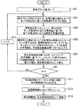
次に、このように構成された電池電源システム3の動作について説明する。図2は、図1に示す電池電源装置1の動作の一例を示すフローチャートである。まず、電池ブロックBB1〜BBmの各二次電池Bに異常がなく、ヒューズFが一つも遮断(溶断)していないときは、電流制限値設定部102によって、電流制限値Iuの初期値として標準電流制限値Isが設定されており、この電流制限値Iuが、充放電制御部21に通知されている。
Next, the operation of the battery
これにより、電池ブロックBB1〜BBmに流れる全体電流値IAAの絶対値は、充放電制御部21によって、標準電流制限値Isを超えないように制限されている。
Thus, the absolute value of the total current value I AA that flows through the battery block BB1~BBm is the charge-
次に、ステップS1において、全体電流検出部AAによって、全体電流値IAAが検出される。そして、有効電池数推定部101によって、電池ブロックBBの番号を示す変数iに、1が代入される(ステップS2)。
Next, in step S1, an overall current value IAA is detected by the overall current detector AA . Then, the effective battery
そして、i番目の電池ブロックBBにおける第1個別電流検出部Axiによって、第1個別電流値IAxiが検出される(ステップS3)。さらに、有効電池数推定部101によって、第1個別電流値IAxiと閾値Izとが比較される(ステップS4)。ここで、閾値Izは、第1個別電流値IAxiが実質的にゼロであるか否かを判定するための判定閾値である。例えば第1個別電流検出部Axiによる電流の検出誤差にある程度の余裕を持たせた値が閾値Izとして予め設定されている。
Then, the first individual current detection unit Axi in the i-th battery block BB detects the first individual current value I Axi (step S3). Further, the effective battery
そして、第1個別電流値IAxiが閾値Izを超えており、すなわち第1個別電流値IAxiがゼロでなければ(ステップS4でYES)、有効電池数推定部101によって、第1個別電流値IAxiが個別電流値IAiとして設定される(ステップS5)。
If the first individual current value I Axi exceeds the threshold value Iz, that is, if the first individual current value I Axi is not zero (YES in Step S4), the effective battery
一方、第1個別電流値IAxiが閾値Iz以下であり、すなわち第1個別電流値IAxiが実質的にゼロであれば(ステップS4でNO)、ヒューズFi−1が遮断して二次電池Bi−1には電流が流れていないと考えられる。そうすると、第1個別電流値IAxiに基づき有効電池数ENiを推定することが出来ない。 On the other hand, if the first individual current value I Axi is less than or equal to the threshold value Iz, that is, if the first individual current value I Axi is substantially zero (NO in step S4), the fuse Fi-1 is cut off and the secondary battery is cut off. It is considered that no current flows through Bi-1. Then, the effective battery number ENi cannot be estimated based on the first individual current value I Axi .
そこで、i番目の電池ブロックBBにおける第2個別電流検出部Ayiによって、第2個別電流値IAyiが検出される(ステップS6)。そして、有効電池数推定部101によって、第2個別電流値IAyiが個別電流値IAiとして設定される(ステップS7)。
Therefore, the second individual current value I Ayi is detected by the second individual current detector Ayi in the i-th battery block BB (step S6). Then, the effective battery
これにより、第1個別電流検出部Axiと直列接続されたヒューズFi−1が遮断した場合であっても、i番目の電池ブロックBBにおける有効電池数ENiを推定することが可能となる。 Thereby, even when the fuse Fi-1 connected in series with the first individual current detection unit Axi is cut off, the number of effective batteries ENi in the i-th battery block BB can be estimated.
次に、有効電池数推定部101によって、全体電流値IAAが個別電流値IAiで除算され、例えば小数点以下が四捨五入されて、i番目の電池ブロックBBにおける有効電池数ENiが算出される(ステップS8)。すなわち、電池ブロックBBiに流れる電流の全体電流値IAAは、ヒューズFが遮断されていない各二次電池Biにほぼ均等に分配され、その分配された一つ分の電流値が、個別電流値IAiとなる。従って、全体電流値IAAを個別電流値IAiで除算することで、有効電池数ENiを算出することが可能となる。
Next, the available battery
次に、有効電池数推定部101によって、変数iが電池ブロック数mと比較され(ステップS9)、変数iが電池ブロック数mに満たなければ(ステップS9でNO)、次の電池ブロックBBについて有効電池数ENiを算出するべく変数iに1が加算されて(ステップS10)、再びステップS3〜S9を繰り返す。
Next, the effective battery
そして、変数iが電池ブロック数m以上となれば(ステップS9でYES)、全ての電池ブロックBBについて有効電池数EN1〜ENmを算出し終えたことになるから、ステップS11へ移行する。 If the variable i is greater than or equal to the number m of battery blocks (YES in step S9), the effective battery numbers EN1 to ENm have been calculated for all the battery blocks BB, and the process proceeds to step S11.
ステップS11では、有効電池数推定部101によって、有効電池数EN1〜ENmのうちの最小値が、有効電池数ENminとして設定される。この有効電池数ENminに基づき電流制限値Iuを設定することで、遮断しているヒューズFの数が最も多く、従って、充放電可能な電流値が最も少ない電池ブロックに合わせて、電流制限値Iuを設定することができる。
In step S11, the effective battery
次に、電流制限値設定部102によって、上記式(1)を用いて、電流制限値Iuが算出される(ステップS12)。式(1)によれば、有効電池数推定部101によって検出された有効電池数ENminが減少するほど電流制限値Iuが小さくなるように、電流制限値Iuが設定される。
Next, the current limit
具体的には、式(1)によれば、ヒューズFが一つも遮断していないときに標準電流制限値Isの電流が電池ブロックBBiに流れた場合に当該電池ブロックにおける二次電池Bi1〜Binのうち一つに流れる電流値を、ヒューズFが1つ又は複数遮断した場合に遮断されていないヒューズFと直列接続された二次電池B一つに流れる電流値が超えないように、電流制限値Iuを設定することができる。 Specifically, according to the formula (1), when the current of the standard current limit value Is flows to the battery block BBi when none of the fuses F is cut off, the secondary batteries Bi1 to Bin in the battery block. The current value flowing in one of the secondary batteries B connected in series with the unfused fuse F when one or more of the fuses F is cut off so as not to exceed the current value flowing in one of them. The value Iu can be set.
次に、電流制限値Iuが、電流制限値設定部102によって通信部11へ出力され、通信部11によって通信部24を介して充放電制御部21へ送信される(ステップS13)。
Next, the current limit value Iu is output to the
これにより、充放電制御部21によって、電池電源装置1の電池ブロックBB1〜BBmに流れる電流値が、電流制限値Iuを超えないように制限されるので、電池ブロックBBに含まれるヒューズFの一部が遮断して一部の二次電池Bが切り離されたために、残りの二次電池Bに流れる電流が増加して残りの二次電池Bを劣化させてしまうおそれが低減される。
As a result, the charge /
なお、電池ブロックBBが複数、直列接続されている例を示したが、電池ブロックBBは一つであってもよい。その場合、ステップS9、S10、S11を省略し、有効電池数ENminの代わりにステップS8で得られた有効電池数ENiを用いるようにすればよい。 In addition, although the example in which the plurality of battery blocks BB are connected in series is shown, the number of battery blocks BB may be one. In this case, steps S9, S10, and S11 may be omitted, and the effective battery number ENi obtained in step S8 may be used instead of the effective battery number ENmin.
また、必ずしも第2個別電流検出部Ayを備える必要はなく、第1個別電流検出部Axのみ用いてステップS4、S6、S7を省略するようにしてもよい。しかしながら、第2個別電流検出部Ayを備えてステップS4、S6、S7を実行すると、第1個別電流検出部Axと直列接続されたヒューズFが遮断してしまった場合であっても有効電池数を算出できる点で、より望ましい。 The second individual current detection unit Ay is not necessarily provided, and steps S4, S6, and S7 may be omitted by using only the first individual current detection unit Ax. However, when steps S4, S6, and S7 are executed with the second individual current detection unit Ay, the number of effective batteries is even if the fuse F connected in series with the first individual current detection unit Ax is cut off. Is more preferable in that it can be calculated.
また、個別電流検出部を二つ備える例を示したが、個別電流検出部を三つ以上備えて、各個別電流検出部の検出電流値が実質的にゼロであった場合に他の個別電流検出部の検出電流値を個別電流値として用いるようにしてもよい。 Moreover, although the example provided with two separate electric current detection parts was shown, when three or more individual electric current detection parts are provided and the detected electric current value of each individual electric current detection part is substantially zero, other individual electric currents are shown. The detection current value of the detection unit may be used as the individual current value.
また、全体電流検出部AAと、第1個別電流検出部Axiと、第2個別電流検出部Ayiと、有効電池数推定部101とによって、有効電池数検出部を構成する例に限らない。例えば、複数の二次電池Bが並列接続された電池ブロックBBの内部抵抗を検出し、ヒューズFが溶断するとその内部抵抗が増大することから、その内部抵抗の変化量に基づき有効電池数を算出するようにしてもよい。しかしながら、例えば内部抵抗値がRiである電池ブロックBBにおいて、n個並列接続された二次電池Bが一つ、ヒューズFの遮断により切り離された場合の内部抵抗値の変化量は、Ri/nより小さい。
Moreover, it is not restricted to the example which comprises an effective battery number detection part by the whole electric current detection part AA, 1st separate current detection part Axi, 2nd separate current detection part Ayi, and the effective battery
それに対し、図1に示す全体電流検出部AAと、第1個別電流検出部Axiと、第2個別電流検出部Ayiと、有効電池数推定部101とによって構成された有効電池数検出部によれば、n個並列接続された二次電池Bが一つ、ヒューズFの遮断により切り離された場合の第1個別電流値IAxi又は第2個別電流値IAyiの変化量は、それぞれIAxi/n、IAyi/nとなるから、遮断された電池数に対して得られる検出値の変化量が、内部抵抗値に基づく場合よりも大きくなる結果、その変化量に基づく有効電池数ENiの算出精度が向上する点で、より望ましい。
On the other hand, according to the effective battery number detection unit configured by the overall current detection unit AA, the first individual current detection unit Axi, the second individual current detection unit Ayi, and the effective battery
また、充放電制御部21が外部装置2に設けられ、通信部11によって電流制限値Iuを送信することで、充放電制御部21によって充放電電流値を制限させる例を示したが、例えば、電池電源装置1が、充放電制御部21を備える構成としてもよい。この場合、充放電制御部21が、電流制限部の一例に相当する。
Moreover, although the charging / discharging
(第2実施形態)
次に、本発明の第2の実施形態に係る電池電源システム3aについて説明する。図3は、本発明の第2の実施形態に係る電池電源システム3aの構成の一例を示すブロック図である。図3に示す電池電源システム3aと図1に示す電池電源システム3とでは、電池電源装置1aの構成が、下記の点で異なる。
(Second Embodiment)
Next, a battery
図3に示す電池電源装置1aは、電池電源装置1における電池ブロックBBの代わりに電池ブロックBBaを備え、制御部10の代わりに制御部10aを備えている。電池ブロックBBaは、電池ブロックBBにおけるヒューズFの代わりに、スイッチング素子SWを備えている。スイッチング素子SWは、例えばFET(Field Effect Transistor)やリレースイッチ等のスイッチング素子である。
A battery
また、電池ブロックBBaに含まれるすべての二次電池Bと直列に、第1個別電流検出部Axiと同様に構成された電流検出部Aが接続され、各二次電池Bに流れる電流値をそれぞれ検出可能とされている。 Moreover, the current detection part A comprised similarly to the 1st separate electric current detection part Axi is connected in series with all the secondary batteries B contained in battery block BBa, and the electric current value which flows into each secondary battery B is respectively shown. It can be detected.
制御部10aは、制御部10における有効電池数推定部101の代わりに、異常検出部103と、開閉制御部104と、有効電池数検出部105とを備えている。
The
異常検出部103は、各電流検出部Aによって検出された電流値が、例えば過電流を示す電流値として予め設定された異常判定値を超えると、当該電流値を検出した電流検出部Aと直列接続された二次電池Bに異常が生じたものと判定する。
When the current value detected by each current detection unit A exceeds an abnormality determination value set in advance as a current value indicating an overcurrent, for example, the
なお、異常検出部103は、各二次電池Bを流れる電流値に基づき異常を検出する例に限らない。例えば、各電池ブロックBBaが、各電流検出部Aの代わりに各二次電池Bの温度を検出する温度センサを備え、異常検出部103は、各温度センサで検出された温度が、予め設定された異常判定値を超えると、当該温度を検出した温度センサと直列接続された二次電池Bに異常が生じたものと判定するようにしてもよい。
The
開閉制御部104は、異常検出部103によって異常が検出されたとき、当該異常が検出された二次電池Bと直列接続されているスイッチング素子SWをオフ(開)させる。また、開閉制御部104は、各スイッチング素子SWのオンオフ状態を示すスイッチング素子情報を、有効電池数検出部105へ送信する。
When the
有効電池数検出部105は、開閉制御部104から送信されたスイッチング素子情報に基づいて、各電池ブロックBに含まれる複数のスイッチング素子SWのうち開閉制御部104が閉じさせているスイッチング素子の数を、有効電池数として検出する。
The effective battery
その他の構成は図1に示す電池電源システム3と同様であるのでその説明を省略する。以下、図3に示す電池電源装置1aの動作について説明する。図4は、図3に示す電池電源装置1aの動作の一例を示すフローチャートである。なお、図4において、図2に示すフローチャートと同様の動作については同じステップ番号を付してその説明を省略する。
Since the other configuration is the same as that of the battery
まず、異常検出部103によって、電池ブロックBBaの番号を示す変数iに、1が代入される(ステップS2)。次に、電池ブロックBBaiにおける、各電流検出部Aによって、電池ブロックBBaiに含まれる各二次電池Biに流れる電流がそれぞれ検出される。そして、その検出された電流値が例えばアナログデジタルコンバータによってデジタル値に変換されて、異常検出部103により取得される(ステップS21)。
First, the
そしてこのようにして得られた各二次電池Biに流れる電流値が、それぞれ異常検出部103によって異常判定値と比較され、異常判定値以下であればその電流が検出された二次電池Biが異常なし、異常判定値を超えていればその電流が検出された二次電池Biが異常有りと判定される(ステップS22)。
Then, the current value flowing through each secondary battery Bi thus obtained is compared with the abnormality determination value by the
次に、異常検出部103によって異常有りと判定された二次電池Biと接続されたスイッチング素子SWiを、開閉制御部104がオフする。そして、各スイッチング素子SWiのオン、オフ状態を示すスイッチング素子情報を、開閉制御部104が、有効電池数検出部105へ出力する(ステップS23)。
Next, the switching
次に、有効電池数検出部105が、スイッチング素子情報に基づいて、電池ブロックBBaiにおける各スイッチング素子SWiのうち開閉制御部104がオン(閉)させているスイッチング素子の数を、有効電池数ENiとして検出する(ステップS24)。
Next, based on the switching element information, the valid battery
このように、遮断素子として開閉制御可能なスイッチング素子を用い、開閉制御部104を用いて、スイッチング素子のオン、オフを制御することにより、異常が検出された二次電池Bに流れる電流を遮断するようにした場合には、開閉制御部104の制御情報(スイッチング素子情報)を用いて、有効電池数ENiを取得することができる。
In this way, the switching element that can be controlled to be opened and closed is used as the blocking element, and the
次に、有効電池数検出部105によって、変数iが電池ブロック数mと比較され(ステップS9)、変数iが電池ブロック数mに満たなければ(ステップS9でNO)、次の電池ブロックBBaについて有効電池数ENiを算出するべく変数iに1加算されて(ステップS10)、再びステップS21〜S24を繰り返す。
Next, the valid battery
そして、変数iが電池ブロック数m以上となれば(ステップS9でYES)、全ての電池ブロックBBaについて有効電池数EN1〜ENmを算出し終えたことになるから、ステップS11へ移行する。以下、ステップS11〜S13の動作は、図2に示すフローチャートと同様であるからその説明を省略する。 If the variable i is greater than or equal to the number of battery blocks m (YES in step S9), the calculation of the effective battery numbers EN1 to ENm has been completed for all the battery blocks BBa, and the process proceeds to step S11. Hereinafter, the operations in steps S11 to S13 are the same as those in the flowchart shown in FIG.
即ち、本発明の一局面に従う電池電源装置は、二次電池と当該二次電池の充放電経路を遮断する遮断状態となり得る遮断素子との直列回路が複数並列に接続された電池ブロックと、前記電池ブロックに流れる電流の電流値である全体電流値の許容値の上限を示す電流制限値を設定する電流制限値設定部と、前記電池ブロックに含まれる複数の前記遮断素子のうち、前記遮断状態ではない遮断素子の数を、有効電池数として検出する有効電池数検出部とを備え、前記電流制限値設定部は、前記有効電池数検出部によって検出された有効電池数が減少するほど前記電流制限値が小さくなるように、前記電流制限値を設定する。 That is, a battery power supply device according to one aspect of the present invention includes a battery block in which a plurality of series circuits of a secondary battery and a blocking element that can block a charge / discharge path of the secondary battery are connected in parallel; A current limit value setting unit that sets a current limit value that indicates an upper limit of an allowable value of an overall current value that is a current value of a current that flows in the battery block; and the cut-off state among the plurality of cut-off elements included in the battery block An effective battery number detection unit that detects the number of non-interrupting elements as an effective battery number, and the current limit value setting unit reduces the current as the number of effective batteries detected by the effective battery number detection unit decreases. The current limit value is set so that the limit value becomes smaller.
この構成によれば、複数並列に接続された二次電池のそれぞれに、充放電経路を遮断するための遮断素子が直列接続されている。そのため、電池ブロックに含まれる一部の二次電池に異常が生じた場合、当該異常が生じた一部の二次電池のみ、遮断素子によって充放電経路を遮断することができる結果、電池電源装置そのものの充放電を禁止することなく、異常が生じた一部の二次電池が劣化するおそれを低減することができる。 According to this structure, the interruption | blocking element for interrupting | blocking a charging / discharging path | route is connected in series with each of the secondary battery connected in parallel. Therefore, when an abnormality occurs in some of the secondary batteries included in the battery block, only a part of the secondary batteries in which the abnormality has occurred can cut off the charge / discharge path by the interruption element. Without prohibiting charging / discharging of the battery itself, it is possible to reduce the possibility of deterioration of some of the secondary batteries in which an abnormality has occurred.
このとき、一部の遮断素子を遮断状態にすると、その遮断素子によって遮断された二次電池に流れていた電流は、充放電経路が遮断されていない残りの二次電池に分配される。そのため、充放電経路が遮断されていない残りの二次電池に流れる電流が増大することとなる。従って、もし仮に電池ブロックに流れる電流の許容値の上限を示す電流制限値が、遮断素子が一つも遮断されていないときのままになっていると、この電流制限値に基づいて電池電源装置の充放電を行う場合、電池ブロック単位では電流制限値以下、すなわち許容範囲内の電流値になっていても、充放電経路が遮断されていない残りの二次電池に流れる電流は、二次電池単体での許容電流値を超えるおそれがある。その結果、二次電池を劣化させてしまうおそれがある。 At this time, when a part of the shut-off elements are put into a shut-off state, the current flowing in the secondary battery cut off by the shut-off element is distributed to the remaining secondary batteries whose charge / discharge paths are not cut off. As a result, the current flowing through the remaining secondary batteries whose charge / discharge paths are not interrupted increases. Therefore, if the current limit value indicating the upper limit of the allowable value of the current flowing through the battery block remains when no interrupting element is interrupted, the battery power When charging / discharging, the current that flows in the remaining secondary batteries that are not interrupted by the charge / discharge path is less than the current limit value in the battery block unit, that is, the current value is within the allowable range. There is a risk of exceeding the allowable current value at. As a result, the secondary battery may be deteriorated.
そこで、有効電池数検出部によって、電池ブロック一つに含まれる複数の遮断素子のうち、遮断状態ではない遮断素子の数が、有効電池数として検出される。そして、電流制限値設定部によって、有効電池数が減少するほど電流制限値が小さくなるように、当該電流制限値が設定される。これにより、一部の遮断素子が遮断状態となった場合、有効電池数が減少して電流制限値が小さくされるので、この電流制限値に基づき電池電源装置の充放電を行うことで、充放電経路が遮断されていない残りの二次電池に流れる電流が減少される。従って、遮断されていない残りの二次電池が劣化するおそれを低減することが容易となる。 Therefore, the effective battery number detection unit detects the number of cutoff elements that are not in the cutoff state among the plurality of cutoff elements included in one battery block as the number of effective batteries. Then, the current limit value setting unit sets the current limit value so that the current limit value decreases as the number of effective batteries decreases. As a result, when some of the breaker elements are cut off, the number of effective batteries is reduced and the current limit value is reduced. The current flowing through the remaining secondary batteries whose discharge paths are not interrupted is reduced. Therefore, it becomes easy to reduce the possibility that the remaining secondary batteries that are not blocked will deteriorate.
また、前記電流制限値設定部は、前記電池ブロックに含まれるすべての前記遮断素子が前記遮断状態でないときにおける前記全体電流値の許容値の上限を標準電流制限値とし、前記電池ブロック一つに含まれる二次電池の数に対する前記有効電池数の比率を有効電池比率とし、前記標準電流制限値と前記有効電池比率とを乗じた値を、前記電流制限値として設定することが好ましい。 In addition, the current limit value setting unit sets the upper limit of the allowable value of the total current value when all of the interrupting elements included in the battery block are not in the interrupted state as a standard current limit value, and It is preferable that the ratio of the number of effective batteries to the number of secondary batteries included is an effective battery ratio, and a value obtained by multiplying the standard current limit value and the effective battery ratio is set as the current limit value.
この構成によれば、電池ブロックに流れる電流値を、電流制限値設定部によって設定された制限電流値を超えないように制限することで、遮断素子が一つも遮断状態になっていないときに電池ブロックへ標準電流制限値の電流が流れた場合に各二次電池に分配されて流れる電流値、すなわち各二次電池の許容電流値を、超えないように制限することができる。従って、二次電池が劣化するおそれを低減することが容易となる。 According to this configuration, by limiting the value of the current flowing through the battery block so as not to exceed the limit current value set by the current limit value setting unit, the battery can be operated when no blocking element is in the blocking state. When the current of the standard current limit value flows to the block, the current value distributed and distributed to each secondary battery, that is, the allowable current value of each secondary battery can be limited so as not to exceed. Therefore, it is easy to reduce the risk of deterioration of the secondary battery.
また、前記有効電池数検出部は、前記全体電流値を検出する全体電流検出部と、前記電池ブロックに含まれる複数の二次電池のうち一つに流れる電流を示す第1個別電流値を検出する第1個別電流検出部と、前記第1個別電流検出部によって検出された第1個別電流値を個別電流値として用い、前記全体電流検出部によって検出された全体電流値と当該個別電流値とに基づいて、前記有効電池数を推定する有効電池数推定部とを含むことが好ましい。 The effective battery number detection unit detects an overall current detection unit for detecting the overall current value, and a first individual current value indicating a current flowing in one of a plurality of secondary batteries included in the battery block. And using the first individual current value detected by the first individual current detector and the first individual current value detected by the first individual current detector as an individual current value, and the individual current value detected by the overall current detector and the individual current value It is preferable that an effective battery number estimation unit for estimating the effective battery number is included.
この構成によれば、電池ブロックに含まれる複数の二次電池のうち一つに流れる電流値が、第1個別電流検出部によって第1個別電流値として検出される。そして、この第1個別電流値は、全体電流検出部によって検出された全体電流値の電流が、遮断されていない有効な二次電池に分配されたものである。そうすると、一部の遮断素子が遮断されて、有効電池数が減少するほど、第1個別電流値は増大することになるから、有効電池数推定部は、全体電流値と第1個別電流値とに基づいて、有効電池数を推定することができる。 According to this configuration, the current value flowing through one of the plurality of secondary batteries included in the battery block is detected as the first individual current value by the first individual current detection unit. The first individual current value is obtained by distributing the current of the total current value detected by the total current detection unit to an effective secondary battery that is not cut off. As a result, the first individual current value increases as a part of the interruption elements are cut off and the number of effective batteries decreases. Therefore, the effective battery number estimation unit calculates the total current value and the first individual current value. Based on the above, the number of effective batteries can be estimated.
また、前記第1個別電流検出部は、ホール素子を用いて構成されていることが好ましい。 In addition, it is preferable that the first individual current detection unit is configured using a Hall element.
第1個別電流検出部は電池ブロックに含まれる複数の二次電池のうち一つと接続されることとなるから、第1個別電流検出部による電圧ロス(電圧降下)が大きいと、第1個別電流検出部が接続された二次電池と他の二次電池との間で印加電圧や充電電流に差異が生じて各二次電池の状態が不均一になる。一方、ホール素子は、電圧ロスが極めて小さいから、第1個別電流検出部としてホール素子を用いると、第1個別電流検出部が接続された二次電池と他の二次電池との間での印加電圧や充電電流の差異が低減できる結果、各二次電池の状態が不均一になるおそれを低減できる。 Since the first individual current detector is connected to one of a plurality of secondary batteries included in the battery block, if the voltage loss (voltage drop) by the first individual current detector is large, the first individual current detector A difference occurs in the applied voltage and the charging current between the secondary battery to which the detection unit is connected and the other secondary battery, and the state of each secondary battery becomes non-uniform. On the other hand, since the Hall element has a very small voltage loss, if the Hall element is used as the first individual current detection unit, the secondary battery between the secondary battery to which the first individual current detection unit is connected and another secondary battery is used. As a result of reducing the difference in applied voltage and charging current, the possibility that the state of each secondary battery becomes non-uniform can be reduced.
また、前記有効電池数検出部は、前記電池ブロックに含まれる複数の二次電池のうち前記第1個別電流検出部により電流が検出される二次電池以外の一つに流れる電流を示す第2個別電流値を検出する第2個別電流検出部をさらに備え、前記有効電池数推定部は、前記第1個別電流検出部によって検出された第1個別電流値が、実質的にゼロであった場合、前記第2個別電流検出部によって検出された第2個別電流値を個別電流値として用い、前記全体電流検出部によって検出された全体電流値と前記個別電流値とに基づいて、前記有効電池数を推定することが好ましい。 The effective battery number detection unit is a second unit that indicates a current flowing through one of the plurality of secondary batteries included in the battery block other than the secondary battery whose current is detected by the first individual current detection unit. A second individual current detection unit that detects an individual current value is further provided, and the effective battery number estimation unit is configured such that the first individual current value detected by the first individual current detection unit is substantially zero. , Using the second individual current value detected by the second individual current detector as the individual current value, and based on the total current value detected by the total current detector and the individual current value, the number of effective batteries Is preferably estimated.
第1個別電流検出部が接続された二次電池と直列接続された遮断素子が遮断されてしまうと、第1個別電流値はゼロになってしまうため、この第1個別電流値に基づいて有効電池数を推定することができなくなる。そこで、有効電池数推定部は、第1個別電流検出部によって検出された第1個別電流値が実質的にゼロであった場合、第2個別電流検出部によって検出された第2個別電流値を個別電流値として用いることで、例え第1個別電流検出部が接続された二次電池と直列接続された遮断素子が遮断された場合であっても、全体電流検出部によって検出された全体電流値と当該個別電流値とに基づいて、有効電池数を推定することができる。 If the interrupting element connected in series with the secondary battery to which the first individual current detection unit is connected is interrupted, the first individual current value becomes zero. Therefore, it is effective based on the first individual current value. The number of batteries cannot be estimated. Therefore, when the first individual current value detected by the first individual current detection unit is substantially zero, the effective battery number estimation unit calculates the second individual current value detected by the second individual current detection unit. The total current value detected by the total current detection unit even when the cutoff element connected in series with the secondary battery to which the first individual current detection unit is connected is cut off by using it as the individual current value. And the number of effective batteries can be estimated based on the individual current value.
また、前記有効電池数推定部は、前記全体電流値を前記個別電流値によって除算することにより、前記有効電池数を推定することが好ましい。 Moreover, it is preferable that the said effective battery number estimation part estimates the said effective battery number by dividing the said whole electric current value by the said separate electric current value.
この構成によれば、有効電池数検出部は、全体電流値を個別電流値によって除算する簡単な演算によって、有効電池数を推定することができるので、簡素な構成で有効電池数検出部を構成することができる。 According to this configuration, since the effective battery number detection unit can estimate the effective battery number by a simple calculation that divides the entire current value by the individual current value, the effective battery number detection unit is configured with a simple configuration. can do.
また、前記遮断素子は、開閉可能なスイッチング素子であり、前記電池電源装置は、前記各二次電池の異常を検出する異常検出部と、前記異常検出部によって異常が検出された二次電池に直列接続されているスイッチング素子を開かせる開閉制御部とをさらに備え、前記有効電池数検出部は、前記電池ブロックに含まれる複数のスイッチング素子のうち前記開閉制御部が閉じさせているスイッチング素子の数を、前記有効電池数として検出するようにしてもよい。 The shut-off element is a switching element that can be opened and closed, and the battery power supply device includes an abnormality detection unit that detects an abnormality of each secondary battery, and a secondary battery in which an abnormality is detected by the abnormality detection unit. An open / close control unit that opens the switching elements connected in series, and the effective battery number detection unit is a switching element that is closed by the open / close control unit among the plurality of switching elements included in the battery block. The number may be detected as the number of effective batteries.
この構成によれば、異常検出部によって異常が検出された二次電池と直列接続されているスイッチング素子が、開閉制御部によってオフされて、当該二次電池が保護される。この場合、開閉制御部によるスイッチング素子の制御内容からスイッチング素子の開閉状態が判るから、有効電池数検出部は、電池ブロックに含まれる複数のスイッチング素子のうち開閉制御部が閉じさせているスイッチング素子の数を、有効電池数として検出することができる。従って、有効電池数を検出することが容易となる。 According to this configuration, the switching element connected in series with the secondary battery in which the abnormality is detected by the abnormality detection unit is turned off by the open / close control unit, and the secondary battery is protected. In this case, since the switching state of the switching element can be determined from the control content of the switching element by the switching control unit, the effective battery number detection unit is a switching element that is closed by the switching control unit among the plurality of switching elements included in the battery block. Can be detected as the number of effective batteries. Therefore, it becomes easy to detect the number of effective batteries.
また、前記各遮断素子は、当該各遮断素子と直列接続された二次電池に異常が生じた場合に前記遮断状態となる保護素子であることが好ましい。 Moreover, it is preferable that each said interruption | blocking element is a protection element which will be in the said interruption | blocking state when abnormality arises in the secondary battery connected in series with the said each interruption | blocking element.
この構成によれば、上述の異常検出部や開閉制御部を備えなくても、各保護素子によって各二次電池が保護されるので、簡素な構成で二次電池の保護を行うことが可能となる。 According to this configuration, since each secondary battery is protected by each protection element without having the above-described abnormality detection unit and opening / closing control unit, it is possible to protect the secondary battery with a simple configuration. Become.
また、前記電池ブロックが複数直列接続されており、前記有効電池数検出部は、前記各電池ブロックに含まれる前記複数の遮断素子のうち、遮断していない遮断素子の数を、前記各電池ブロックにおける個別の有効電池数としてそれぞれ検出し、前記電流制限値設定部は、前記有効電池数検出部によって検出された複数の前記個別の有効電池数のうちの最小値を前記有効電池数として用いることが好ましい。 In addition, a plurality of the battery blocks are connected in series, and the effective battery number detection unit determines the number of non-blocking blocking elements among the plurality of blocking elements included in each battery block. And the current limit value setting unit uses a minimum value among the plurality of individual effective batteries detected by the effective battery number detection unit as the number of effective batteries. Is preferred.
この構成によれば、複数の二次電池が並列接続された電池ブロックが、複数直列接続されている場合、各電池ブロックのうち最も有効電池数が少なく、従って二次電池一つに分配される電流が最も多くなる電池ブロックにおいても、二次電池一つに流れる電流が当該二次電池の許容電流値を超えないように、電流制限値を設定することができる。 According to this configuration, when a plurality of battery blocks in which a plurality of secondary batteries are connected in parallel are connected in series, the number of effective batteries is the smallest among the battery blocks, and thus the battery blocks are distributed to one secondary battery. Even in the battery block with the largest current, the current limit value can be set so that the current flowing through one secondary battery does not exceed the allowable current value of the secondary battery.
また、前記全体電流値が、前記電流制限値設定部によって設定された電流制限値を超えないように前記電池ブロックに流れる電流を制御する電流制御部をさらに備えることが好ましい。 Moreover, it is preferable to further include a current control unit that controls the current flowing through the battery block so that the total current value does not exceed the current limit value set by the current limit value setting unit.
この構成によれば、電流制御部によって、電池ブロックに流れる電流が、電流制限値設定部によって設定された電流制限値を超えないように制御される。その結果、一部の遮断素子が遮断した場合であっても、遮断されていない残りの二次電池に流れる電流が増大するおそれが低減されるので、二次電池が劣化するおそれを低減することができる。 According to this configuration, the current control unit controls the current flowing through the battery block so as not to exceed the current limit value set by the current limit value setting unit. As a result, even if a part of the shut-off elements are shut off, the risk of increasing the current flowing in the remaining secondary batteries that are not shut off is reduced, thereby reducing the risk of secondary battery deterioration. Can do.
また、前記電流制御部は、前記電池ブロックを充放電する外部装置へ、前記電流制限値設定部で設定された電流制限値を送信することによって、前記電池ブロックに流れる電流が当該電流制限値を超えないように前記外部装置によって制御させるようにしてもよい。 The current control unit transmits the current limit value set by the current limit value setting unit to an external device that charges and discharges the battery block, so that the current flowing through the battery block has the current limit value. You may make it control by the said external device so that it may not exceed.
この構成によれば、電池ブロックの充放電が電池電源装置の外部に設けられた外部装置によって制御されている場合であっても、電流制御部によって、外部装置へ電流制限値が送信されて、電池ブロックに流れる電流が当該電流制限値を超えないように前記外部装置によって制御させることができる。従って、一部の遮断素子が遮断した場合であっても、遮断されていない残りの二次電池に流れる電流が増大するおそれが低減される結果、二次電池が劣化するおそれを低減することができる。 According to this configuration, even when charging / discharging of the battery block is controlled by an external device provided outside the battery power supply device, the current control unit transmits a current limit value to the external device, It can be controlled by the external device so that the current flowing through the battery block does not exceed the current limit value. Therefore, even when some of the shut-off elements are shut off, the possibility of increasing the current flowing through the remaining secondary batteries that are not shut off is reduced, and as a result, the risk of deterioration of the secondary battery can be reduced. it can.
また、本発明の一局面に従う電池電源システムは、上述の電池電源装置と、前記電池電源装置を充放電する外部装置をと備え、前記外部装置は、前記電池ブロックからの放電電流の供給を受け付ける負荷回路と、前記電池ブロックへ充電電流を供給する電流供給部と、前記電池ブロックに流れる電流が、前記電流制御部から送信された前記電流制限値を超えないように、前記電池ブロックから前記負荷回路へ供給される放電電流、及び前記電流供給部から前記電池ブロックへ供給される充電電流を調節する充放電制御部とを備える。 A battery power supply system according to one aspect of the present invention includes the battery power supply device described above and an external device that charges and discharges the battery power supply device, and the external device accepts supply of a discharge current from the battery block. A load circuit; a current supply unit that supplies a charging current to the battery block; and a current that flows through the battery block from the battery block so as not to exceed the current limit value transmitted from the current control unit. A charge / discharge control unit that adjusts a discharge current supplied to the circuit and a charge current supplied from the current supply unit to the battery block.
この構成によれば、上述の電池電源装置と、この電池電源装置の電池ブロックからの放電電流の供給を受け付ける負荷回路と、この電池ブロックへ充電電流を供給する電流供給部とを備えた電池電源システムにおいて、電池ブロックに含まれる一部の二次電池に異常が生じた場合であっても、電池電源装置全体の充放電を禁止することなく、二次電池が劣化するおそれを低減することができる。 According to this configuration, the battery power supply including the battery power supply device described above, a load circuit that receives supply of a discharge current from the battery block of the battery power supply device, and a current supply unit that supplies a charging current to the battery block. In the system, even if an abnormality occurs in some secondary batteries included in the battery block, the possibility of deterioration of the secondary battery can be reduced without prohibiting charging / discharging of the entire battery power supply device. it can.
この出願は、2009年11月6日に出願された日本国特許出願特願2009−255000を基礎とするものであり、その内容は、本願に含まれるものである。 This application is based on Japanese Patent Application No. 2009-255000 filed on Nov. 6, 2009, the contents of which are included in the present application.
なお、発明を実施するための形態の項においてなされた具体的な実施態様又は実施例は、あくまでも、本発明の技術内容を明らかにするものであって、そのような具体例にのみ限定して狭義に解釈されるべきものではなく、本発明の精神と特許請求事項との範囲内で、種々変更して実施することができるものである。 Note that the specific embodiments or examples made in the section for carrying out the invention are to clarify the technical contents of the present invention, and are limited to such specific examples. The present invention should not be interpreted in a narrow sense, and various modifications can be made within the spirit and scope of the present invention.
本発明に係る電池電源装置、及びこれを用いた電池電源システムは、携帯型パーソナルコンピュータやデジタルカメラ、携帯電話機等の電子機器、電気自動車やハイブリッドカー等の車両、ハイブリッドエレベータ、太陽電池や発電装置と二次電池とを組み合わされた電源システム、無停電源装置等の電池搭載装置、システムにおいて、好適に利用することができる。 A battery power supply apparatus according to the present invention and a battery power supply system using the battery power supply apparatus include electronic devices such as portable personal computers, digital cameras and mobile phones, vehicles such as electric vehicles and hybrid cars, hybrid elevators, solar cells and power generation devices. Can be suitably used in battery-mounted devices and systems such as a power supply system in which a battery and a secondary battery are combined, and a non-disruptive power supply device.
Claims (10)
前記電池ブロックに流れる電流の電流値である全体電流値の許容値の上限を示す電流制限値を設定する電流制限値設定部と、
前記電池ブロックに含まれる複数の前記遮断素子のうち、前記遮断状態ではない遮断素子の数を、有効電池数として検出する有効電池数検出部とを備え、
前記電流制限値設定部は、
前記有効電池数検出部によって検出された有効電池数が減少するほど前記電流制限値が小さくなるように、前記電流制限値を設定し、
前記有効電池数検出部は、
前記全体電流値を検出する全体電流検出部と、
前記電池ブロックに含まれる複数の二次電池のうち一つに流れる電流を示す第1個別電流値を検出する第1個別電流検出部と、
前記第1個別電流検出部によって検出された第1個別電流値を個別電流値として用い、前記全体電流検出部によって検出された全体電流値と当該個別電流値とに基づいて、前記有効電池数を推定する有効電池数推定部とを含む電池電源装置。A battery block in which a plurality of series circuits of a secondary battery and a blocking element that can be in a blocking state that blocks a charge / discharge path of the secondary battery are connected in parallel;
A current limit value setting unit for setting a current limit value indicating an upper limit of an allowable value of the entire current value which is a current value of a current flowing through the battery block;
An effective battery number detection unit that detects the number of non-blocking elements among the plurality of blocking elements included in the battery block as the number of effective batteries;
The current limit value setting unit includes:
The current limit value is set so that the current limit value decreases as the number of effective batteries detected by the effective battery number detection unit decreases.
The effective battery number detection unit
An overall current detector for detecting the overall current value;
A first individual current detector that detects a first individual current value indicating a current flowing in one of a plurality of secondary batteries included in the battery block;
The first individual current value detected by the first individual current detection unit is used as an individual current value, and the number of effective batteries is calculated based on the total current value detected by the total current detection unit and the individual current value. A battery power supply device including an effective battery number estimation unit for estimation.
前記電池ブロックに含まれるすべての前記遮断素子が前記遮断状態でないときにおける前記全体電流値の許容値の上限を標準電流制限値とし、前記電池ブロック一つに含まれる二次電池の数に対する前記有効電池数の比率を有効電池比率とし、前記標準電流制限値と前記有効電池比率とを乗じた値を、前記電流制限値として設定する請求項1記載の電池電源装置。The current limit value setting unit includes:
The upper limit of the allowable value of the total current value when all the shut-off elements included in the battery block are not in the shut-off state is set as a standard current limit value, and the effective with respect to the number of secondary batteries included in the battery block The battery power supply device according to claim 1, wherein a ratio of the number of batteries is set as an effective battery ratio, and a value obtained by multiplying the standard current limit value and the effective battery ratio is set as the current limit value.
ホール素子を用いて構成されている請求項1又は2記載の電池電源装置。The first individual current detector is
The battery power supply device according to claim 1, wherein the battery power supply device is configured using a Hall element.
前記電池ブロックに含まれる前記複数の二次電池のうち前記第1個別電流検出部により電流が検出される二次電池以外の一つに流れる電流を示す第2個別電流値を検出する第2個別電流検出部をさらに備え、
前記有効電池数推定部は、
前記第1個別電流検出部によって検出された第1個別電流値が、実質的にゼロであった場合、前記第2個別電流検出部によって検出された第2個別電流値を個別電流値として用い、前記全体電流検出部によって検出された全体電流値と前記個別電流値とに基づいて、前記有効電池数を推定する
請求項1〜3のいずれか1項に記載の電池電源装置。The effective battery number detection unit
A second individual for detecting a second individual current value indicating a current flowing in one of the plurality of secondary batteries included in the battery block other than the secondary battery whose current is detected by the first individual current detector. A current detection unit;
The effective battery number estimation unit includes:
When the first individual current value detected by the first individual current detection unit is substantially zero, the second individual current value detected by the second individual current detection unit is used as the individual current value. The battery power supply device according to any one of claims 1 to 3, wherein the number of effective batteries is estimated based on an overall current value detected by the overall current detection unit and the individual current value.
前記全体電流値を前記個別電流値によって除算することにより、前記有効電池数を推定する請求項1〜4のいずれか1項に記載の電池電源装置。The effective battery number estimation unit includes:
The battery power supply device according to claim 1, wherein the number of effective batteries is estimated by dividing the total current value by the individual current value.
当該各遮断素子と直列接続された二次電池に異常が生じた場合に前記遮断状態となる保護素子である請求項1〜5のいずれか1項に記載の電池電源装置。Each of the blocking elements is
The battery power supply device according to any one of claims 1 to 5, wherein the battery power supply device is a protective element that enters the cut-off state when an abnormality occurs in a secondary battery connected in series with the cut-off elements.
前記有効電池数検出部は、
前記各電池ブロックに含まれる前記複数の遮断素子のうち、遮断していない遮断素子の数を、前記各電池ブロックにおける個別の有効電池数としてそれぞれ検出し、
前記電流制限値設定部は、
前記有効電池数検出部によって検出された複数の前記個別の有効電池数のうちの最小値を前記有効電池数として用いる請求項1〜6のいずれか1項に記載の電池電源装置。A plurality of the battery blocks are connected in series,
The effective battery number detection unit
Among the plurality of blocking elements included in each battery block, the number of blocking elements that are not blocked is detected as the number of individual effective batteries in each battery block,
The current limit value setting unit includes:
The battery power supply device according to any one of claims 1 to 6 , wherein a minimum value among a plurality of the individual effective battery numbers detected by the effective battery number detection unit is used as the effective battery number.
前記電池ブロックを充放電する外部装置へ、前記電流制限値設定部で設定された電流制限値を送信することによって、前記電池ブロックに流れる電流が当該電流制限値を超えないように前記外部装置によって制御させる請求項8に記載の電池電源装置。The current controller is
By transmitting the current limit value set by the current limit value setting unit to an external device that charges and discharges the battery block, the external device prevents the current flowing through the battery block from exceeding the current limit value. The battery power supply device according to claim 8 to be controlled.
前記電池電源装置を充放電する外部装置をと備え、
前記外部装置は、
前記電池ブロックからの放電電流の供給を受け付ける負荷回路と、
前記電池ブロックへ充電電流を供給する電流供給部と、
前記電池ブロックに流れる電流が、前記電流制御部から送信された前記電流制限値を超えないように、前記電池ブロックから前記負荷回路へ供給される放電電流、及び前記電流供給部から前記電池ブロックへ供給される充電電流を調節する充放電制御部と
を備える電池電源システム。The battery power supply device according to any one of claims 1 to 9 ,
An external device for charging and discharging the battery power supply device;
The external device is
A load circuit for receiving a supply of discharge current from the battery block;
A current supply unit for supplying a charging current to the battery block;
The discharge current supplied from the battery block to the load circuit and the current supply unit to the battery block so that the current flowing through the battery block does not exceed the current limit value transmitted from the current control unit. A battery power supply system comprising: a charge / discharge control unit that adjusts a supplied charging current.
Priority Applications (1)
| Application Number | Priority Date | Filing Date | Title |
|---|---|---|---|
| JP2011510601A JP5082011B2 (en) | 2009-11-06 | 2010-10-19 | Battery power supply and battery power supply system |
Applications Claiming Priority (4)
| Application Number | Priority Date | Filing Date | Title |
|---|---|---|---|
| JP2009255000 | 2009-11-06 | ||
| JP2009255000 | 2009-11-06 | ||
| JP2011510601A JP5082011B2 (en) | 2009-11-06 | 2010-10-19 | Battery power supply and battery power supply system |
| PCT/JP2010/006205 WO2011055499A1 (en) | 2009-11-06 | 2010-10-19 | Battery power supply device, and battery power supply system |
Publications (2)
| Publication Number | Publication Date |
|---|---|
| JP5082011B2 true JP5082011B2 (en) | 2012-11-28 |
| JPWO2011055499A1 JPWO2011055499A1 (en) | 2013-03-21 |
Family
ID=43969743
Family Applications (1)
| Application Number | Title | Priority Date | Filing Date |
|---|---|---|---|
| JP2011510601A Expired - Fee Related JP5082011B2 (en) | 2009-11-06 | 2010-10-19 | Battery power supply and battery power supply system |
Country Status (6)
| Country | Link |
|---|---|
| US (1) | US20110291619A1 (en) |
| EP (1) | EP2385575A1 (en) |
| JP (1) | JP5082011B2 (en) |
| KR (1) | KR20110111528A (en) |
| CN (1) | CN102939682A (en) |
| WO (1) | WO2011055499A1 (en) |
Families Citing this family (28)
| Publication number | Priority date | Publication date | Assignee | Title |
|---|---|---|---|---|
| WO2012132246A1 (en) * | 2011-03-31 | 2012-10-04 | パナソニック株式会社 | Battery power supply apparatus and battery power supply system |
| JP6044114B2 (en) * | 2011-06-03 | 2016-12-14 | 株式会社Gsユアサ | State determination device, power storage device, and state determination method |
| US9419457B2 (en) | 2012-09-04 | 2016-08-16 | Google Technology Holdings LLC | Method and device with enhanced battery capacity savings |
| US9356461B2 (en) | 2012-09-25 | 2016-05-31 | Google Technology Holdings, LLC | Methods and systems for rapid wireless charging where the low state of charge (SOC) temperature dependent charging current and low SOC temperature limit are higher than the high SOC temperature dependent charging current and high SOC temperature limit |
| JP6116223B2 (en) * | 2012-12-13 | 2017-04-19 | デクセリアルズ株式会社 | Protection circuit, battery unit |
| JP6223171B2 (en) | 2012-12-28 | 2017-11-01 | 株式会社半導体エネルギー研究所 | Power storage device control system, power storage system, and electrical device |
| US9491706B2 (en) | 2013-03-13 | 2016-11-08 | Google Technology Holdings LLC | Reduced-power transmitting from a communications device |
| US9596653B2 (en) | 2013-12-16 | 2017-03-14 | Google Technology Holdings LLC | Remedying power drain via a coverage map |
| JP5925755B2 (en) * | 2013-12-20 | 2016-05-25 | プライムアースEvエナジー株式会社 | Battery module adjustment method and battery module adjustment apparatus |
| US9865897B2 (en) | 2014-06-02 | 2018-01-09 | Google Llc | Stacked electrochemical cell with increased energy density |
| JP6314701B2 (en) * | 2014-07-01 | 2018-04-25 | 日産自動車株式会社 | Capacitor connection state control device |
| US9438293B2 (en) | 2014-08-05 | 2016-09-06 | Google Technology Holdings LLC | Tunable circuit elements for dynamic, per element power |
| US9472965B2 (en) | 2014-09-08 | 2016-10-18 | Google Technology Holdings LLC | Battery cycle life through smart overnight charging |
| CN104466068B (en) * | 2014-10-27 | 2017-02-15 | 深圳市快车道新能源发展有限公司 | Method for connecting storage battery combined system |
| JP2019068489A (en) * | 2016-02-25 | 2019-04-25 | 三洋電機株式会社 | Electrical power system |
| US10840725B2 (en) | 2016-07-10 | 2020-11-17 | Gbatteries Energy Canada Inc. | Battery charging with charging parameters sweep |
| JP6753272B2 (en) * | 2016-11-02 | 2020-09-09 | 富士通株式会社 | Power supply and discharge / charge control method |
| DE102016122438A1 (en) | 2016-11-22 | 2018-05-24 | HELLA GmbH & Co. KGaA | Two-voltage battery with current sensors and calibration method for this |
| US10250045B2 (en) * | 2017-01-05 | 2019-04-02 | Gbatteries Energy Canada Inc. | System and method for battery pack |
| WO2018138843A1 (en) * | 2017-01-26 | 2018-08-02 | 株式会社ソニー・インタラクティブエンタテインメント | Electrical device |
| JP6853143B2 (en) * | 2017-08-22 | 2021-03-31 | トヨタ自動車株式会社 | Power supply |
| US11108251B2 (en) | 2019-02-22 | 2021-08-31 | Aurora Flight Sciences Corporation | Battery management system |
| US11133534B2 (en) | 2019-02-22 | 2021-09-28 | Aurora Flight Sciences Corporation | Programmable battery pack |
| JP7441059B2 (en) * | 2020-01-29 | 2024-02-29 | キヤノン株式会社 | Battery pack, control method and program |
| JP7364064B2 (en) * | 2020-05-22 | 2023-10-18 | 株式会社村田製作所 | Battery system control method and battery system |
| JP7388318B2 (en) * | 2020-09-02 | 2023-11-29 | トヨタ自動車株式会社 | power supply |
| JP7552455B2 (en) * | 2021-03-12 | 2024-09-18 | トヨタ自動車株式会社 | Battery resistance measuring device, vehicle, and battery resistance measuring method |
| KR20220152827A (en) * | 2021-05-10 | 2022-11-17 | 현대자동차주식회사 | Apparatus for managing battery of vehicle and method thereof |
Citations (4)
| Publication number | Priority date | Publication date | Assignee | Title |
|---|---|---|---|---|
| JP2001185228A (en) * | 1999-12-24 | 2001-07-06 | Sanyo Electric Co Ltd | Electric power supply equipped with battery |
| JP2007110887A (en) * | 2005-09-14 | 2007-04-26 | Fuji Electric Systems Co Ltd | Battery charge / discharge switch system |
| JP2007282375A (en) * | 2006-04-06 | 2007-10-25 | Hitachi Vehicle Energy Ltd | Hybrid vehicle control system and hybrid vehicle control method |
| JP2010088202A (en) * | 2008-09-30 | 2010-04-15 | Toshiba Corp | Battery unit and battery system using the same |
Family Cites Families (4)
| Publication number | Priority date | Publication date | Assignee | Title |
|---|---|---|---|---|
| JP5097365B2 (en) | 2006-07-19 | 2012-12-12 | パナソニック株式会社 | Battery pack and disconnection detection method thereof |
| JP4945206B2 (en) | 2006-09-13 | 2012-06-06 | パナソニック株式会社 | Battery pack and disconnection detection method thereof |
| US7777451B2 (en) * | 2007-04-17 | 2010-08-17 | Chun-Chieh Chang | Rechargeable battery assembly and power system using same |
| JP2009255000A (en) | 2008-04-18 | 2009-11-05 | Ebara Engineering Service Co Ltd | Apparatus for supplying staple fiber |
-
2010
- 2010-10-19 KR KR1020117020417A patent/KR20110111528A/en not_active Abandoned
- 2010-10-19 CN CN2010800070413A patent/CN102939682A/en active Pending
- 2010-10-19 EP EP10828061A patent/EP2385575A1/en not_active Withdrawn
- 2010-10-19 WO PCT/JP2010/006205 patent/WO2011055499A1/en not_active Ceased
- 2010-10-19 JP JP2011510601A patent/JP5082011B2/en not_active Expired - Fee Related
- 2010-10-19 US US13/201,384 patent/US20110291619A1/en not_active Abandoned
Patent Citations (4)
| Publication number | Priority date | Publication date | Assignee | Title |
|---|---|---|---|---|
| JP2001185228A (en) * | 1999-12-24 | 2001-07-06 | Sanyo Electric Co Ltd | Electric power supply equipped with battery |
| JP2007110887A (en) * | 2005-09-14 | 2007-04-26 | Fuji Electric Systems Co Ltd | Battery charge / discharge switch system |
| JP2007282375A (en) * | 2006-04-06 | 2007-10-25 | Hitachi Vehicle Energy Ltd | Hybrid vehicle control system and hybrid vehicle control method |
| JP2010088202A (en) * | 2008-09-30 | 2010-04-15 | Toshiba Corp | Battery unit and battery system using the same |
Also Published As
| Publication number | Publication date |
|---|---|
| JPWO2011055499A1 (en) | 2013-03-21 |
| EP2385575A1 (en) | 2011-11-09 |
| US20110291619A1 (en) | 2011-12-01 |
| WO2011055499A1 (en) | 2011-05-12 |
| CN102939682A (en) | 2013-02-20 |
| KR20110111528A (en) | 2011-10-11 |
Similar Documents
| Publication | Publication Date | Title |
|---|---|---|
| JP5082011B2 (en) | Battery power supply and battery power supply system | |
| JP6955972B2 (en) | Control devices, control systems, power storage devices and programs | |
| KR102818308B1 (en) | Apparatus and method for managing battery | |
| JP7130907B2 (en) | Apparatus, battery system and method for controlling main battery and sub-battery | |
| JP7001229B2 (en) | Overcharge prevention device and method | |
| CN102326313B (en) | Charging control circuit, battery pack, and charging system | |
| CN106324318B (en) | Method for measuring battery current | |
| KR102365552B1 (en) | Multiple parallel connected high voltage batteries control device and method | |
| KR101262524B1 (en) | Overcurrent protection apparatus for secondary bettery, protection method and battery pack | |
| WO2012132246A1 (en) | Battery power supply apparatus and battery power supply system | |
| EP2717415A1 (en) | Electricity storage system | |
| US20110291481A1 (en) | Power source apparatus with fuse-implemented over-current cut-off | |
| KR20160099357A (en) | Battery pack and battery system including the same | |
| JPWO2020080543A1 (en) | Power storage system | |
| KR20110134751A (en) | Battery pack and its control method | |
| US11552483B2 (en) | Electric storage system | |
| KR101174893B1 (en) | A battery pack and method for controlling the battery pack | |
| US10391880B2 (en) | Battery pack and electric vehicle including the same | |
| US8890536B2 (en) | Secondary battery with apparatus for checking the state of a service plug | |
| JP5361529B2 (en) | Lithium-ion battery charge control device and lithium-ion battery system | |
| JP2008043009A (en) | Battery pack and control method | |
| KR20210028356A (en) | Battery disconnect apparatus, battery apparatus and method of preventing power disconnect | |
| KR102343790B1 (en) | Battery management system and method for managing battery | |
| JP2012198170A (en) | Battery power supply device | |
| JP7457203B2 (en) | A method for detecting defective battery cells and a battery management system providing the method |
Legal Events
| Date | Code | Title | Description |
|---|---|---|---|
| TRDD | Decision of grant or rejection written | ||
| A01 | Written decision to grant a patent or to grant a registration (utility model) |
Free format text: JAPANESE INTERMEDIATE CODE: A01 Effective date: 20120807 |
|
| A01 | Written decision to grant a patent or to grant a registration (utility model) |
Free format text: JAPANESE INTERMEDIATE CODE: A01 |
|
| A61 | First payment of annual fees (during grant procedure) |
Free format text: JAPANESE INTERMEDIATE CODE: A61 Effective date: 20120903 |
|
| FPAY | Renewal fee payment (event date is renewal date of database) |
Free format text: PAYMENT UNTIL: 20150907 Year of fee payment: 3 |
|
| R150 | Certificate of patent or registration of utility model |
Free format text: JAPANESE INTERMEDIATE CODE: R150 |
|
| LAPS | Cancellation because of no payment of annual fees |