This application claims 2015 priority from korean patent application No. 10-2015-0094929, filed by the korean intellectual property office on 7/2, the disclosure of which is hereby incorporated by reference in its entirety.
Disclosure of Invention
One or more exemplary embodiments include a method of measuring a current of a battery pack using a current sensor with a low measurement error by correcting an offset of the current sensor.
Additional aspects will be set forth in part in the description which follows, and in part will be obvious from the description, or may be learned by practice of the present embodiments.
According to one or more exemplary embodiments, there is provided a method of measuring a current of a battery pack including a rechargeable battery, a main switch connected in series with the battery, and a precharge switch connected in parallel with the main switch, the method including: turning on a precharge switch and turning off a main switch; measuring a voltage between two terminals of the main switch; calculating a precharge current flowing through the precharge switch by considering a resistance of a precharge resistor connected in series with the precharge switch; measuring a current of the battery pack using a current sensor; comparing the current measured with the current sensor with a pre-charge current; and correcting an offset of the current sensor based on a result of the comparison.
The turning on of the precharge switch and the turning off of the main switch may be performed when the current measured using the current sensor is equal to or lower than a first critical value for a preset period of time.
The first critical value may correspond to a standby current of the battery pack.
The current sensor may periodically measure the current while the pre-charge switch is turned on and the main switch is turned off.
The correction of the offset of the current sensor may be performed when a difference between the precharge current and the current measured using the current sensor is equal to or greater than a second critical value.
The precharge switch may interrupt an overcurrent flowing to or from the battery pack.
The method may further include turning on the main switch and turning off the precharge switch after performing the measurement of the current of the battery pack.
The current sensor may include a hall sensor, and the current sensor may be connected in series between the battery and the main switch.
The main switch may electrically connect the battery to the charge-discharge terminal of the battery pack.
The main switch may include a first relay, and the pre-charge switch includes a second relay, wherein the first relay may have a larger capacity than the second relay.
As described above, according to the method of measuring the battery pack current of one or more of the above-described exemplary embodiments, the error of the measurement is minimized by correcting the offset of the current sensor.
In some embodiments of this implementation, the first path includes a current sensor and a first switch.
In some embodiments of this implementation, the second path includes a resistor and a second switch, and wherein the current on the second path is determined by measuring a voltage across the resistor when the second switch is closed and dividing the measured voltage by the resistance.
In some embodiments of this implementation, interrupting the current flowing through the first path is performed when the measured current is equal to or below a first threshold value for a preset period of time.
In some embodiments of this implementation, the first threshold comprises a standby current of the battery pack.
In some embodiments of this implementation, there is the step of calculating a corrected current value by subtracting the offset from the current measured on the first path.
In some embodiments of this implementation, the corrected current value is calculated when the current on the first path is equal to or greater than the second threshold value.
In some embodiments of this implementation, after determining the magnitude of the current flowing on the second path, the second path is disabled and the first path is enabled.
Detailed Description
Reference will now be made in detail to exemplary embodiments, examples of which are illustrated in the accompanying drawings. These exemplary embodiments may take different forms and should not be construed as limited to the description set forth herein. Accordingly, the exemplary embodiments are described below merely with reference to the accompanying drawings to illustrate aspects of the present specification. As used herein, the term "and/or" includes any and all combinations of one or more of the associated listed items.
In the following description, technical terms are used only to illustrate specific exemplary embodiments, and do not limit the inventive concept. Terms in the singular may include the plural unless mentioned to the contrary. The meaning of "comprising" or "including" indicates attributes, fixed numbers, steps, procedures, elements, components and combinations thereof, but does not exclude other attributes, fixed numbers, steps, procedures, elements, components and combinations thereof. It will be understood that, although the terms first and second may be used herein to describe various elements, these elements should not be limited by these terms. These terms are only used to distinguish one element from another.
Hereinafter, exemplary embodiments will be described in detail with reference to the accompanying drawings. Like numbers refer to like elements throughout. In the drawings, like reference numerals refer to like or corresponding elements, and a repetitive description thereof will be omitted.
Fig. 2 is a view illustrating an exemplary structure of the battery pack 100.
The battery pack 100 shown in fig. 2 is an example for explaining a method of measuring a battery pack current according to an exemplary embodiment of the present disclosure. That is, the battery pack current measuring method of the exemplary embodiment is not limited to the use of the battery pack 100.
Referring to fig. 2, the battery pack 100 includes a rechargeable battery 110 (hereinafter, referred to as a battery 110), a main switch 121 connected in series with the battery 110, and a pre-charge switch 122 connected in parallel with the main switch 121. The battery 110 may include one or more rechargeable battery cells 111.
The battery cells 111 may be connected in series, parallel, or series-parallel. The number of battery cells 111 included in the battery 110 may vary depending on a required output voltage.
The battery 110 may be connected to a load or charger through charge-discharge terminals P + and P-. In the discharge mode, the battery pack 100 supplies electric energy to a load through the charge-discharge terminals P + and P-, and in the charge mode, the battery pack 100 stores electric energy received from a charger through the charge-discharge terminals P + and P-. If the battery pack 100 is connected to a pure electric vehicle configured to operate using only electric energy or an electric vehicle such as a hybrid vehicle configured to operate using electric energy and fossil fuel, the load may be a driving motor of the electric vehicle, and the charger may be a charger of the electric vehicle or a regenerative generator of the electric vehicle that converts kinetic energy into electric energy during braking.
If a power converter connected between the battery pack 100 and one or more of the power generation system, the load, and the grid is combined with the battery pack 100 to form an energy storage device, the load may be the load and/or the grid, and the charger may be the power generation system and/or the grid.
The battery cell 111 may include a rechargeable battery cell. For example, the battery cells 111 may include nickel cadmium battery cells, lead battery cells, Nickel Metal Hydride (NMH) battery cells, lithium ion battery cells, lithium polymer battery cells, and the like.
The main switch 121 is connected in series between the positive terminal of the battery 110 and the charge-discharge terminal P +. The precharge switch 122 is connected in parallel with the main switch 121. If the main switch 121 is instantaneously turned on, an instantaneous inrush current may be applied to a high-voltage circuit component so that the high-voltage circuit component may be destroyed or the main switch 121 may be blown. Therefore, the precharge switch 122 is connected in series with the precharge resistor 123 and is turned on before the main switch 121 is turned on to limit the current peak.
For example, the precharge switch 122 and the precharge resistor 123 are precharged by the current output from the battery 110 before the current reaches the main switch 121, thereby preventing an arc discharge that may occur in the case where the current directly reaches the main switch 121. Accordingly, the battery pack 100 may have improved circuit stability.
For this, the precharge switch 122 may be connected in parallel with the main switch 121, and the precharge resistor 123 may be connected in series with the precharge switch 122.
The main switch 121 may include a first relay, and the precharge switch 122 may include a second relay. The capacity of the first relay may be greater than the capacity of the second relay.
The main switch 121 is disposed along a path through which a discharging current of the battery 110 flows or a charging current of an external charger flows to the battery 110. Therefore, generally, a high current flows through the main switch 121. However, a relatively low current flows through the precharge switch 122 compared to the current flowing through the main switch 121. Accordingly, the first relay of the main switch 121 may have a capacity greater than that of the second relay of the precharge switch 122.
In addition, the battery pack 100 may include a current sensor 130. The current sensor 130 may be connected in series between the battery 110 and the main switch 121 to measure a discharge current output from the battery 110 and/or a charge current input to the battery 110. The current sensor 130 may be a hall sensor.
In addition, the battery pack 100 may further include a Battery Management System (BMS) 140. The BMS 140 sets a protection level for the battery 110, and the BMS 140 may interrupt the charging current if the charging current flowing to the battery 110 is equal to or higher than the protection level.
The BMS 140 monitors the state of the battery 110 and controls the overall operation of the battery 110, such as charging and discharging operations. The BMS 140 may measure parameters of the battery pack 100, such as cell voltage, temperature, charge current, or discharge current, and may control charge and discharge operations of the battery 110 based on the measured data. Based on the measured data, the BMS 140 may calculate a remaining power, a life span (life span), or an SOC of the battery 110 or may determine whether the battery 110 has an error. For example, the BMS 140 may determine whether the battery 110 has an error such as overcharge, overdischarge, overcurrent, overvoltage, overheat, cell unbalance, or cell degradation. If it is determined that the battery 110 has an error, the BMS 140 may take action according to an internal algorithm. For example, the BMS 140 may control a charging switch and/or a discharging switch or cut a fuse. In addition, the BMS 140 may control the balance between the battery cells 111 of the battery 110 based on the measured data and a preset algorithm.
The current value measured by the current sensor 130 may be transmitted to the BMS 140, and the BMS 140 may control the battery 110 based on the current value received from the current sensor 130.
Fig. 3 to 6 are flowcharts illustrating a method of measuring a battery pack current according to an exemplary embodiment.
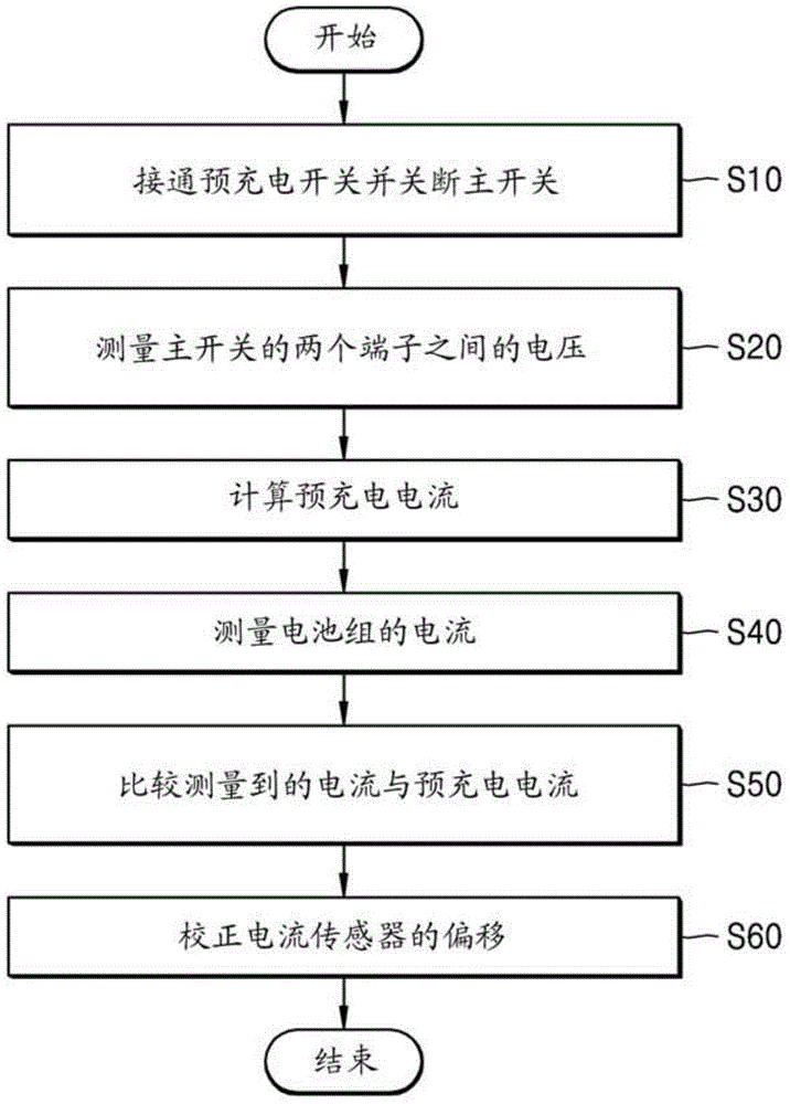
First, referring to fig. 3, a method of measuring a battery pack current will be described according to an exemplary embodiment. According to an exemplary embodiment, a method of measuring a battery current includes: turning on the precharge switch and turning off the main switch (operation S10); measuring a voltage between both terminals of the main switch (operation S20); calculating a precharge current (operation S30); measuring a current of the battery pack (S40); comparing the measured current with a precharge current (S50); the offset of the current sensor is corrected (S60).
The method of measuring battery current is for a battery, such as battery 100 described with reference to fig. 2. The description of fig. 3-6 may be made more clear later by referring to the description provided with reference to fig. 2. However, as described above, the battery pack 100 shown in fig. 2 is an example. That is, it will be apparent to those of ordinary skill in the art that the method of measuring the battery pack current of the exemplary embodiment may be applied to other battery packs including elements other than those included in the battery pack 100.
In operation S10 of the method of measuring a battery pack current of the exemplary embodiment, the precharge switch 122 (refer to fig. 2) may be turned on, and the main switch 121 (refer to fig. 2) may be turned off. That is, before the method of measuring the battery pack current is performed, the precharge switch 122 of the battery pack 100 may be in an off state, and the main switch 121 may be in an on state.
If the battery pack 100 is connected to an electric vehicle and the main switch 121 is turned on, the discharge current of the battery pack 100 is applied to a driving motor of the electric vehicle. In this case, the driving motor may be regarded as a load that receives electric energy from the battery pack 100. The pre-charge switch 122 may be turned on before the main switch 121 is turned off, especially in order to prevent a sudden interruption of the supply of electrical energy to the load. However, if it is not necessary to continuously supply the electric energy to the load, the pre-charge switch 122 may be turned on after the main switch 121 is turned off.
In operation S20, a voltage between two terminals of the main switch 121 is measured. That is, the potential difference between the positive terminal of the battery 110 and the charge-discharge terminal P + of the battery pack 100 is measured. Referring to fig. 2, the measurement of the voltage between the two terminals of the main switch 121 in operation S20 may be understood as a measurement of a potential difference between the node B + and the node P +.
The voltage between both terminals of the main switch 121 may be equal to the voltage applied to the overcurrent prevention circuit composed of the precharge switch 122 and the precharge resistor 123 (refer to fig. 2).
In operation S20, the voltage between the two terminals of the main switch 121 may be measured by the BMS 140 (refer to fig. 2), and the BMS 140 may store the measured voltage in a separate memory.
In the precharge current calculation operation S30, the current flowing through the precharge switch 122 may be calculated.
The resistance of the precharge resistor 123 has been given, and the voltages applied to the precharge resistor 123 and the precharge switch 122 have been measured in operation S20. Therefore, the current flowing through the precharge switch 122, that is, the precharge current, can be calculated in terms of the relationship between the voltage, the resistance, and the current.
The precharge current calculation operation S30 may be performed by the BMS 140, and the BMS 140 may store the calculated precharge current in a separate memory.
In operation S40, the current sensor 130 may measure the current of the battery pack 100. As described with reference to fig. 2, the current sensor 130 may be connected in series between the battery 110 and the main switch 121. The current sensor 130 may be a hall sensor.
The BMS 140 may receive the current value measured using the current sensor 130 and store the measured current value.
In operation S50, a precharge current calculated as a current flowing through the precharge resistor 123 and the precharge switch 122 is compared with a current of the battery pack 100 measured using the current sensor 130.
When the main switch 121 is turned off, the battery 110, the precharge resistor 123, and the precharge switch 122 are connected in series. Thus, the current of the battery pack 100 measured by the current sensor 130 is predicted to be equal to the precharge current calculated as the current flowing through the precharge resistor 123 and the precharge switch 122.
However, in general, the current measured with the sensor may be different from the actual current because of the offset of the sensor. In operation S50, the precharge current is compared with the current measured by the current sensor 130 to determine whether the current sensor 130 accurately measures the current actually flowing.
In operation S60, the offset of the current sensor 130 is corrected based on the result of operation S50 of comparing the precharge current with the current measured with the current sensor 130. For example, if the current measured with the current sensor 130 is 1.1A and the precharge current is 1.0A, it is determined that the offset of the current sensor 130 is +0.1A in operation S60. Thereafter, when the current of the battery pack 100 is measured using the current sensor 130, a current value lower than the current measured using the current sensor 130 by 0.1A may be considered as an actual current value of the battery pack 100.
In addition, in operation S60, the offset of the current sensor 130 may be determined to be + 10%, and thus when the current of the battery pack 100 is measured, it may be determined that the actual current of the battery pack 100 is 1/1.1 times the current measured using the current sensor 130.
Fig. 4 is a flowchart illustrating a method of measuring a battery pack current according to another exemplary embodiment. Referring to the flowchart of fig. 4, operation S20 of measuring the voltage between the two terminals of the main switch to operation S60 of correcting the offset of the current sensor are substantially the same as operation S20 of measuring the voltage between the two terminals of the main switch to operation S60 of correcting the offset of the current sensor, which are performed in the method of measuring the battery pack current described with reference to fig. 3, so that a repetitive description thereof will be omitted.
Referring to fig. 4, the method of measuring the battery pack current may further include an operation S11 of determining whether the current measured using the current sensor is lower than a first critical value for a preset period of time, before the operation S12 of turning on the precharge switch and turning off the main switch.
In operation S11, if the measured current is lower than the first critical value for a preset time period, operation S12 is performed to turn on the precharge switch and turn off the main switch. If not, that is, the measured currents are not all below the first critical value for the preset time period, the operation S12 of turning on the precharge switch and turning off the main switch is not performed. Instead, the current of the battery pack is measured again using the current sensor. Operation S11 may be performed periodically.
The first threshold value may be equal to a standby current of the battery pack. For example, when the battery pack is connected to an electric vehicle, if the main switch is turned off in a general driving mode of the electric vehicle, the main switch may be destroyed because a high discharge current is output from the battery pack in the general driving mode. In this case, the discharge current of the battery pack may be output using the precharge switch. However, this reduces efficiency because of the voltage drop at the pre-charge resistor.
Therefore, it can be determined whether or not the main switch can be turned off without a problem. For example, if the discharge current of the battery pack is low, such as when the electric vehicle is stationary or moving on a downhill slope, the main switch may be turned off without problems.
In operation S11, the current of the battery pack may be periodically measured using the current sensor, and it may be determined whether to proceed with the next operation to correct the offset of the current sensor.
Fig. 5 is a flowchart illustrating a method of measuring a battery pack current according to another exemplary embodiment. Referring to the flowchart of fig. 5, operation S10 of turning on the precharge switch and turning off the main switch to operation S50 of comparing current values is substantially the same as operation S10 of turning on the precharge switch and turning off the main switch to operation S50 of comparing current values, which is performed in the method of measuring battery pack current described with reference to fig. 3, so that a repetitive description thereof will be omitted.
Referring to fig. 5, before operation S62 of correcting the offset of the current sensor, but after operation S50 of comparing the current measured using the current sensor with the precharge current, the method of measuring the battery pack current may further include operation S61 of determining whether a difference between the measured current and the precharge current is equal to or greater than a second critical value.
In operation S61, if the difference between the current of the battery pack measured using the current sensor and the precharge current is lower than the second critical value, operation S10 is performed again instead of correcting the offset of the current sensor.
The second critical value may be expressed as a percentage (%) or amperes (a) and may vary depending on the characteristics of the battery pack or the characteristics of a system including the battery pack. In addition, the second critical value may represent an allowable error range or a numerical error value of the battery pack.
That is, if the difference between the current of the battery pack measured with the current sensor and the precharge current is within the allowable range, the offset of the current sensor is not corrected.
However, if the difference between the current of the battery pack measured using the current sensor and the precharge current is equal to or greater than the second critical value, it is determined that the current sensor has an unallowable error, and thus operation S62 is performed to correct the offset of the current sensor.
Fig. 6 is a flowchart illustrating a method of measuring a battery pack current according to another exemplary embodiment. Referring to the flowchart of fig. 6, operations other than the operation S42 of turning on the main switch and turning off the precharge switch are substantially the same as those of the method of measuring the battery pack current described with reference to fig. 3, so that a repetitive description thereof will be omitted.
Referring to fig. 6, after operation S41 of measuring the current of the battery pack, operation S42 is performed to turn on the main switch and turn off the precharge switch.
The precharge switch is turned on and the main switch is turned off to correct the offset of the current sensor while a relatively low discharge current flows. That is, after operation S30 of calculating the precharge current and operation S41 of measuring the current of the battery pack using the current sensor, all data necessary to correct the offset of the current sensor may be obtained.
Therefore, after operation S41 of measuring the current of the battery pack, the main switch may be turned on and the precharge switch may be turned off in preparation for a high discharge current that may be output from the battery.
The operation S42 of turning on the main switch and turning off the precharge switch is performed after measuring the current of the battery pack using the current sensor, but is not limited to being performed before the operation S50 of comparing the measured current with the precharge current.
As described with reference to fig. 1 to 6, according to the method of measuring the current of the battery pack according to the exemplary embodiment, a measurement error caused by an offset of the current sensor may be corrected, and the current of the battery pack may be measured more accurately.
The flowcharts shown in fig. 3 to 6 are examples. For example, one of ordinary skill in the art will readily envision a battery current measurement method that includes all of the operations described with reference to fig. 3-6.
It should be understood that the exemplary embodiments described herein should be considered in a descriptive sense only and not for purposes of limitation. Descriptions of features or aspects within each exemplary embodiment should generally be considered as available for other similar features or aspects in other exemplary embodiments.
While one or more exemplary embodiments have been described with reference to the accompanying drawings, it will be understood by those of ordinary skill in the art that various changes in form and details may be made therein without departing from the spirit and scope as defined by the appended claims.