JP5080948B2 - Image forming apparatus and control method thereof - Google Patents
Image forming apparatus and control method thereof Download PDFInfo
- Publication number
- JP5080948B2 JP5080948B2 JP2007303538A JP2007303538A JP5080948B2 JP 5080948 B2 JP5080948 B2 JP 5080948B2 JP 2007303538 A JP2007303538 A JP 2007303538A JP 2007303538 A JP2007303538 A JP 2007303538A JP 5080948 B2 JP5080948 B2 JP 5080948B2
- Authority
- JP
- Japan
- Prior art keywords
- line
- color
- pixel
- data
- image
- Prior art date
- Legal status (The legal status is an assumption and is not a legal conclusion. Google has not performed a legal analysis and makes no representation as to the accuracy of the status listed.)
- Expired - Fee Related
Links
Images


Classifications
-
- B—PERFORMING OPERATIONS; TRANSPORTING
- B41—PRINTING; LINING MACHINES; TYPEWRITERS; STAMPS
- B41J—TYPEWRITERS; SELECTIVE PRINTING MECHANISMS, i.e. MECHANISMS PRINTING OTHERWISE THAN FROM A FORME; CORRECTION OF TYPOGRAPHICAL ERRORS
- B41J2/00—Typewriters or selective printing mechanisms characterised by the printing or marking process for which they are designed
- B41J2/435—Typewriters or selective printing mechanisms characterised by the printing or marking process for which they are designed characterised by selective application of radiation to a printing material or impression-transfer material
- B41J2/47—Typewriters or selective printing mechanisms characterised by the printing or marking process for which they are designed characterised by selective application of radiation to a printing material or impression-transfer material using the combination of scanning and modulation of light
- B41J2/471—Typewriters or selective printing mechanisms characterised by the printing or marking process for which they are designed characterised by selective application of radiation to a printing material or impression-transfer material using the combination of scanning and modulation of light using dot sequential main scanning by means of a light deflector, e.g. a rotating polygonal mirror
- B41J2/473—Typewriters or selective printing mechanisms characterised by the printing or marking process for which they are designed characterised by selective application of radiation to a printing material or impression-transfer material using the combination of scanning and modulation of light using dot sequential main scanning by means of a light deflector, e.g. a rotating polygonal mirror using multiple light beams, wavelengths or colours
-
- G—PHYSICS
- G03—PHOTOGRAPHY; CINEMATOGRAPHY; ANALOGOUS TECHNIQUES USING WAVES OTHER THAN OPTICAL WAVES; ELECTROGRAPHY; HOLOGRAPHY
- G03G—ELECTROGRAPHY; ELECTROPHOTOGRAPHY; MAGNETOGRAPHY
- G03G15/00—Apparatus for electrographic processes using a charge pattern
- G03G15/22—Apparatus for electrographic processes using a charge pattern involving the combination of more than one step according to groups G03G13/02 - G03G13/20
- G03G15/32—Apparatus for electrographic processes using a charge pattern involving the combination of more than one step according to groups G03G13/02 - G03G13/20 in which the charge pattern is formed dotwise, e.g. by a thermal head
- G03G15/326—Apparatus for electrographic processes using a charge pattern involving the combination of more than one step according to groups G03G13/02 - G03G13/20 in which the charge pattern is formed dotwise, e.g. by a thermal head by application of light, e.g. using a LED array
-
- G—PHYSICS
- G03—PHOTOGRAPHY; CINEMATOGRAPHY; ANALOGOUS TECHNIQUES USING WAVES OTHER THAN OPTICAL WAVES; ELECTROGRAPHY; HOLOGRAPHY
- G03G—ELECTROGRAPHY; ELECTROPHOTOGRAPHY; MAGNETOGRAPHY
- G03G15/00—Apparatus for electrographic processes using a charge pattern
- G03G15/04—Apparatus for electrographic processes using a charge pattern for exposing, i.e. imagewise exposure by optically projecting the original image on a photoconductive recording material
- G03G15/041—Apparatus for electrographic processes using a charge pattern for exposing, i.e. imagewise exposure by optically projecting the original image on a photoconductive recording material with variable magnification
-
- G—PHYSICS
- G03—PHOTOGRAPHY; CINEMATOGRAPHY; ANALOGOUS TECHNIQUES USING WAVES OTHER THAN OPTICAL WAVES; ELECTROGRAPHY; HOLOGRAPHY
- G03G—ELECTROGRAPHY; ELECTROPHOTOGRAPHY; MAGNETOGRAPHY
- G03G2215/00—Apparatus for electrophotographic processes
- G03G2215/04—Arrangements for exposing and producing an image
- G03G2215/0402—Exposure devices
- G03G2215/0404—Laser
Description
本発明は、画像形成装置に係り、とりわけ、光ビームを用いて画像を形成する画像形成装置における走査線の湾曲を補正する技術に関する。 The present invention relates to an image forming apparatus, and more particularly to a technique for correcting the curvature of a scanning line in an image forming apparatus that forms an image using a light beam.
従来、画像形成装置に関して、高画質化・高速化・高機能化のニーズがある。とりわけ、レーザ走査型の画像形成装置では、画像形成位置の精度を高く保つために、幾何精度の高い高価な部品(レーザ走査のためのレンズや支持部材、回転多面体など)が用いられてきた。 Conventionally, there is a need for higher image quality, higher speed, and higher functionality for image forming apparatuses. In particular, in a laser scanning type image forming apparatus, expensive parts with high geometric accuracy (such as a lens, a support member, and a rotating polyhedron for laser scanning) have been used in order to maintain high accuracy of the image forming position.
一方で、装置本体をより安価にして欲しいというニーズもある。これを実現するには、幾何精度の高い高価な部品をできる限り削減することが望ましい。そこで、画像処理やレーザPWMに代表されるデジタル補正技術を用いることで、要求される幾何精度を低下させ、安価に装置を構成する技術が提案されている。 On the other hand, there is also a need to make the device body cheaper. To achieve this, it is desirable to reduce as many expensive parts as possible with high geometric accuracy. In view of this, there has been proposed a technique for reducing the geometric accuracy required by using a digital correction technique typified by image processing or laser PWM and configuring the apparatus at low cost.
ところで、カラープリンタなどでは、レーザによる走査線の湾曲をいかにして補正するかが課題となっている。回転多面鏡、fθレンズ、ミラーを用いた一般的なカラープリンタでは、特に、fθレンズの製造誤差や光路からの取り付け誤差によって、走査線の湾曲が発生する。一方で、ミラーの傾斜や像担持体の傾斜によって、走査線の傾斜が発生する。 By the way, in a color printer or the like, a problem is how to correct the curvature of the scanning line caused by the laser. In a general color printer using a rotary polygon mirror, an fθ lens, and a mirror, the scanning line is bent due to a manufacturing error of the fθ lens and a mounting error from the optical path. On the other hand, the scanning line is inclined due to the inclination of the mirror and the inclination of the image carrier.
この走査線の湾曲や傾斜を補正する方法としては、機械式の方法と、画像処理による方法とがある。機械式の方法は、光学部品などを移動させることで、走査線の湾曲や傾斜を補正する。しかし、この方法は、光学部品などを移動させるための機械的な部品を追加しなければならず、装置を安価にすべきとの要請に反する。 As a method for correcting the curvature and inclination of the scanning line, there are a mechanical method and a method using image processing. In the mechanical method, the curvature or inclination of the scanning line is corrected by moving an optical component or the like. However, this method has to add a mechanical part for moving an optical part or the like, and is contrary to the request that the apparatus should be inexpensive.
一方で、画像処理による方法では、2次元配列された画素からなるデジタル画像を、湾曲点に合わせて副走査方向にシフトすることで、湾曲や傾斜を補正する(特許文献1〜3)。具体的には、1ラインを構成する画素の一部を対応する走査線ではなく、そのとなりの走査線によって画像形成することが提案されている。すなわち、走査線の乗り換えが行われている。以下、これらの走査線の傾斜も含めた走査線の理想位置からのずれ・歪みを、湾曲と呼ぶこととする。
図9には、湾曲した走査線の補正前の様子と補正後の様子とが示されている。図からわかるように、補正によって理想位置からのずれや歪みを低減することができる。しかし、補正部分では1走査線分の段差が生じてしまう。画像データの内容によっては、この段差が視認可能となり、画像劣化となってしまう。 FIG. 9 shows a state before correction of a curved scanning line and a state after correction. As can be seen from the figure, the deviation and distortion from the ideal position can be reduced by the correction. However, a step for one scanning line occurs in the correction portion. Depending on the contents of the image data, this step can be visually recognized, resulting in image degradation.
1走査線段差を見えにくくする方法として、画像濃度演算処理(以下ブレンド処理)を施すことが考えられる。ブレンド処理は、1走査線分の画像データを2走査線に分散させることで、乗り換え点に発生した段差を視認しにくくする処理である。 As a method for making one scanning line step difficult to see, it is conceivable to perform image density calculation processing (hereinafter referred to as blend processing). The blending process is a process that makes it difficult to visually recognize a step generated at a transfer point by dispersing image data for one scanning line into two scanning lines.
しかし、このような単純なブレンド処理では、YMCKを重ね合わせて画像を形成するカラープリンタで「YとMを重ね合わせた2次色の純粋な1走査線幅の横線データ」を描画する場合に問題が生じうる。なお、Yはイエロー、Mはマゼンタ、Cはシアン、Kはブラックお略語である。 However, in such a simple blending process, when a color printer that forms an image by superimposing YMCK is used to draw “pseudo horizontal line data of a secondary color obtained by superimposing Y and M”. Problems can arise. Y is yellow, M is magenta, C is cyan, and K is black.
Y色に対してのみ副走査方向の湾曲補正を適用したとしよう。すなわち、副走査方向において隣り合った2つの走査線に対して、Y色がブレンド処理されたとする。この場合、Y色の走査線とそれに重ねられるM色の走査線とでは、レーザ走査線幅(レーザスポット径)で2対1の差が生じるため、Y色とM色間の色ずれが顕著となる。特に、コントラストの強い2次色による細線データや文字データでは、補正による段差が視認可能となってしまう。画素形成の正確さにもよるが、600dpi以下の解像度で顕著となりうる。 Suppose that the curvature correction in the sub-scanning direction is applied only to the Y color. That is, it is assumed that the Y color is blended with respect to two scanning lines adjacent in the sub-scanning direction. In this case, since there is a 2-to-1 difference in the laser scanning line width (laser spot diameter) between the Y scanning line and the M scanning line superimposed thereon, the color shift between the Y and M colors is significant. It becomes. In particular, in thin line data or character data with a secondary color having a high contrast, a step due to correction becomes visible. Although it depends on the accuracy of pixel formation, it can be noticeable at a resolution of 600 dpi or less.
そこで、本発明は、このような課題および他の課題のうち、少なくとも1つを解決することを目的とする。例えば、多色の画像形成装置においても比較的安価な構成によって走査線の湾曲を補正しつつ、色ずれも視認されにくくすることを目的とする。なお、他の課題については明細書の全体を通して理解できよう。 Therefore, an object of the present invention is to solve at least one of such problems and other problems. For example, even in a multi-color image forming apparatus, an object is to make it difficult to visually recognize a color shift while correcting the curvature of a scanning line with a relatively inexpensive configuration. Other issues can be understood throughout the specification.
本発明の技術思想は、例えば、画像データに応じた光を、回転する感光体の上で走査し、走査された光により前記感光体に形成された潜像を現像し、現像された画像を記録シートに転写する画像形成装置に適用される。シフト処理部は、第1色の走査線の湾曲を補正するために画像データにおける注目ラインの画素の一部を隣接したラインの画素へシフトする。緩和処理部は、画素の境界付近に存在する複数の画素の濃度を調整することで、境界に生じた段差を緩和する。境界は、注目ラインから隣接したラインへとシフトした画素と、シフトしなかった画素またはこのラインとは異なるラインへシフトした画素との境界である。さらに、変更部は、第1色のラインに対して重ねて形成される第2色のラインについて境界付近の太さが太くなるよう境界付近の画素のデータを変更する。 The technical idea of the present invention is that, for example, light corresponding to image data is scanned on a rotating photoconductor, the latent image formed on the photoconductor is developed by the scanned light, and the developed image is displayed. The present invention is applied to an image forming apparatus that transfers to a recording sheet . Shift processing unit, it shifts to pixels of adjacent lines a part of the pixel line of interest in the image data in order to correct the curvature of the first color scanning line. Relaxation treatment unit, by adjusting the concentration of a plurality of pixels existing in the vicinity of the boundary of the pixel, to alleviate the step occurring at the boundary. The boundary is a boundary between a pixel shifted from the target line to an adjacent line and a pixel not shifted or a pixel shifted to a line different from this line . Further, the changing unit changes the data of the pixel of the second color in the vicinity of the boundary such that the thickness near the boundary becomes thick for the line to be formed overlapping the first color line.
本発明によれば、第1色の乗り換え点付近に施されたブレンド処理によって生じた線幅の増加に伴う色ずれの発生を、第2色の線幅を増加させることで、視認しにくくする。これにより、多色の画像形成装置においても比較的安価な構成によって走査線の湾曲を補正しつつ、色ずれも視認しにくくなる。 According to the present invention, the occurrence of color misregistration accompanying the increase in the line width caused by the blending process performed in the vicinity of the transfer point of the first color is made difficult to visually recognize by increasing the line width of the second color. . Accordingly, even in a multicolor image forming apparatus, it is difficult to visually recognize a color shift while correcting the curvature of the scanning line with a relatively inexpensive configuration.
以下に本発明の一実施形態を示す。以下で説明される個別の実施形態は、本発明の上位概念、中位概念および下位概念など種々の概念を理解するために役立つであろう。また、本発明の技術的範囲は、特許請求の範囲によって確定されるのであって、以下の個別の実施形態によって限定されるわけではない。 An embodiment of the present invention is shown below. The individual embodiments described below will help to understand various concepts, such as the superordinate concept, intermediate concept and subordinate concept of the present invention. Further, the technical scope of the present invention is determined by the scope of the claims, and is not limited by the following individual embodiments.
[第1の実施形態]
<画像形成装置の構成>
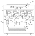
図1は、実施例に係る複数の色を重ね合わせて多色画像を形成する画像形成装置の概略断面図である。この画像形成装置は、4つの感光体をタンデムに配した4ドラム系のカラー複写機を示している。なお、画像形成装置は、例えば、印刷装置、プリンタ、複合機、ファクシミリとして実現されてもよい。また、本発明を適用する上では、色の数は、少なくとも2色あればよい。よって、感光体も2つ以上であればよい。以下では、このカラー複写機100を構成するカラー画像読み取り装置(以下「カラースキャナ」という。)1及びカラー画像記録装置(以下「カラープリンタ」という。)2の概略について説明する。
[First Embodiment]
<Configuration of image forming apparatus>
FIG. 1 is a schematic cross-sectional view of an image forming apparatus that forms a multicolor image by superimposing a plurality of colors according to the embodiment. This image forming apparatus is a four-drum color copying machine in which four photoconductors are arranged in tandem. Note that the image forming apparatus may be realized as, for example, a printing apparatus, a printer, a multifunction peripheral, or a facsimile. In applying the present invention, the number of colors may be at least two. Therefore, it is sufficient that there are two or more photoreceptors. In the following, an outline of a color image reading apparatus (hereinafter referred to as “color scanner”) 1 and a color image recording apparatus (hereinafter referred to as “color printer”) 2 constituting the
カラースキャナ1は、照明ランプ14、ミラー群15A、B、C、及びレンズ16を介してカラーセンサーであるCCDセンサ17に原稿13の画像を結像させる。さらに、カラースキャナ1は、原稿のカラー画像情報を、例えばブルー(以下Bという)、グリーン(以下Gという)、レッド(以下Rという)の色分解光ごとに読み取り、電気的な画像信号に変換する。
The
カラースキャナ1は、B、G、Rの各画像信号の強度レベルをもとにして、色変換処理を行う。これにより、ブラック(K)、シアン(C)、マゼンタ(M)、イエロー(Y)のカラー画像データが得られる。
The
次に、カラープリンタ2について説明する。各色のトナーに対し1つずつ、書き込み光学ユニット28M(マゼンタ用)、28Y(イエロー用)、28C(シアン用)、28K(ブラック用)が設けられている。なお、参照番号に付されたサフィックス、MYCKは、トナーの色を示している。サフィックスであるMYCKは、共通の事項について説明するときは省略される。これらの書き込み光学ユニット28は、各色ごとに、蓄積手段から読み出された画素のデータにより変調されたビームを用いて対応する像担持体を走査する各色ごとの走査手段の一例である。書き込み光学ユニットは、露光装置やスキャナ装置と呼ばれることもある。
Next, the
書き込み光学ユニットは、カラースキャナ1からのカラー画像データを光信号に変換して、光書き込みを行う。これにより、各色ごとに設けられた感光体21M、21Y、21C、21Kに静電潜像が形成される。これらの感光体は、像担持体の一例である。
The writing optical unit converts the color image data from the
これら感光体21M、21Y、21C、21Kは、矢印が示すように反時計回転する。感光体の周辺には、感光体を一様に帯電させるための帯電器27M、27Y、27C、27Kが設けられている。また、現像剤(例:トナー)を用いて静電潜像を現像するための、M現像器213M、C現像器213C、Y現像器213Y、Bk現像器213Kも配置されている。また、中間転写体としての中間転写ベルト22は、駆動ローラ220と、従動ローラ219、237に張架されている。なお、各感光体に対向するように、第1の転写手段である第1転写バイアスブレード217M、217Y、217C、217Kも設けられている。
These
第2転写バイアスローラ221は、従動ローラ219に対向する位置に配置されている。第2転写バイアスローラ221は、不図示の離接機構により、中間転写ベルト22に対して離間したり、接したりする。
The second
カラープリンタ2において、まずマゼンタから画像形成が開始される。その後、中間転写ベルト22の回転速度に対し、感光体21Mと感光体21Cとの離間距離に対応して遅れたタイミングでシアンの画像形成が開始される。次に中間転写ベルト22の回転速度に対し、感光体21Cと感光体21Yとの離間距離に対応して遅れたタイミングでイエローの画像形成が開始される。最後に、中間転写ベルト22の回転速度に対し、感光体21Yと感光体21Kの位置との離間距離に対応して遅れたタイミングでブラックの画像形成が開始される。このように、中間転写ベルト22上には、各色の現像剤像が重ね合わされ多色画像が形成される。この多色画像は、従動ローラ219と第2転写バイアスローラ221とによって形成される2次転写位置において、搬送ローラ228、227、226、225によって搬送されてきた記録材に転写される。その後、定着装置25において、記録材は、その表面にカラー画像が定着処理される。なお、記録材は、例えば、記録媒体、用紙、シート、転写材、転写紙と呼ばれることもある。
In the
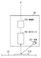
中間転写ベルト22の周辺には、パッチ検知センサ80が設けられている。パッチ検知センサ80は、色ずれなどを検知するパッチを検知するセンサである。
A
図2は、パッチ検センサの一例を示す図である。パッチ検知センサ80は、例えば、光を出力する光源201、中間転写ベルト22に形成されたパッチ210からの反射光を受光する受光センサ202、受光センサ202からの信号を増幅する増幅器203を備えている。
FIG. 2 is a diagram illustrating an example of a patch detection sensor. The
<制御ユニットの構成>
図3は、本実施形態に係る制御ユニットのブロック図を示す。コントローラ部218のCPU301には、制御プログラムが書き込まれたROM303、処理を行うためのデータを格納するRAM302がそれぞれアドレスバス及びデータバスを介して接続されている。また、CPU301には、外部I/F部304、MFP制御部305、内部I/F部306及び操作部307が接続されている。
外部I/F部304は、外部と通信を行うための通信ユニットである。MFP制御部305は、原稿13のスキャン画像データや外部I/F部304からのPDLデータの加工、蓄積、画像処理を行う。内部I/F部306は、プリンタ制御部59との通信するための通信ユニットである。操作部307は、表示装置や入力装置を備えている。
<Configuration of control unit>
FIG. 3 is a block diagram of the control unit according to the present embodiment. A
The external I /
プリンタ制御部59のCPU311は、画像形成動作の基本制御を行う。CPU311には、制御プログラムが書き込まれたROM313及び画像形成動作の処理を行うためのデータを格納するRAM312がアドレスバス及びデータバスを介して接続されている。ROM313には、後述する制御手順等が記憶されているものとする。デバイス制御部314は、カラープリンタ2の各構成部品を制御するための入出力ポート等を含む電気回路である。内部I/F部315は、コントローラ部218と、画像信号やタイミング信号の送受信を行う通信ユニットである。装置間I/F部316は、不図示のシート処理装置と、シート情報やタイミング情報の送受信を行う通信ユニットである。例えば、CPU311は、制御プログラムに従って、コントローラ部218から内部I/F部315を介して画像信号を受信し、デバイス制御部314を制御して画像形成動作を実行する。
The
<MFP制御部の構成>
図4は、MFP制御部の一例を示すブロック図である。MFP制御部305に入力される画像データには、例えば、カラースキャナ1のCCDセンサ17から出力された画像データと、ホストコンピュータなどから外部I/F部304を介して受信された画像データとがある。
<Configuration of MFP control unit>
FIG. 4 is a block diagram illustrating an example of the MFP control unit. The image data input to the
CCDセンサ17に結像された原稿画像を、CCDセンサ17がアナログ電気信号に変換する。アナログ信号処理部400が、変換された画像情報に対してダークレベルの補正等を行う。次に、A/D・SH処理部401は、画像情報をアナログ・デジタル変換(A/D変換)し、デジタル化された信号に対してシェーディング補正を行う。シェーディング補正では、CCDセンサ17が持つ画素ごとのばらつきや原稿照明ランプの配光特性に基づく光量のばらつきが補正される。
The original image formed on the
RGBライン間補正部402は、シェーディング補正された信号に対してRGBライン間補正を行う。ある時点でCCDセンサ17のRGB各受光部に入力した光は、原稿上ではRGB各受光部の位置関係に応じてずれている。そのため、ここでRGB信号間の同期が捕捉される。その後、色変換部403が、ダイレクトマッピングによりRGB信号をYMC信号に変換する。次に下地除去部404は、Y、M、C信号からK信号を生成する。この場合、Y、M、C信号の濃度のうち、最小値をグレー成分として減算することで、それぞれの濃度信号Dy、Dm、Dcが得られる。そしてグレー成分にゲイン調整を施してKの濃度信号Dkが得られる。得られた濃度信号は、メモリ部405に格納される。
The RGB
一方、RIP部410は、外部I/F部304から入力されたPDLデータを解析し、規格化されたL*a*b*空間のデータに変換し、このL*a*b*データを再度ターゲットとなるプリンタに適したYMCK空間のデータに変換する。さらに、RIP部410は、Y、M、C、K信号を生成してメモリ部405へ格納する。
On the other hand, the
画像補正部420は、メモリ部405に格納された画像データの濃度を、パッチ検知センサ80により検出されたパッチの濃度を基準として補正する。補正が必要ない画像データは、直接、メモリ部405からガンマ補正部406へ入力される。
The
ガンマ補正部406は、Y、M、C、Kについて、それぞれルックアップテーブルを用いて、カラープリンタ2の初期設定時における画像濃度とγ特性に従って処理された出力濃度画像が一致するように画像濃度信号を生成する。画像処理部407は、この画像濃度信号をパルス幅変調し、書き込み光学ユニット28M〜28Kのレーザードライバへ出力する。パターンジェネレータ430は、上述したパッチのパターン(画像データ)を発生する。
The
<潜像を形成するためのレーザ走査>
図5は、画像処理部407の一例と静電潜像の形成を説明するための図である。半導体レーザ素子501は、光ビームを出力する光源の一例である。ポリゴンミラーおよびその駆動装置502は、光ビームを回転しながら偏向する回転多面鏡とそれを駆動するモータなどである。主走査書出位置センサ503は、レーザ走査の開始タイミングを認識するために利用されるフォトセンサである。fθレンズ504は、偏向走査された光ビームが感光体上を等速で走査するよう変換する光学部品である。信号線505は、半導体レーザ素子501に駆動信号を供給する信号線である。レーザ光路506は、偏向走査された光ビームが通過する光路である。ミラー507は、レーザ光路506を水平から下方へと変換するミラーである。これらの部品によって、書き込み光学ユニット28が構成されている。感光体駆動装置522は、感光体21を駆動するモータなどである。
<Laser scanning to form a latent image>
FIG. 5 is a diagram for explaining an example of the
画像データ保持部551は、ガンマ補正部406やパターンジェネレータ430から入力された画像データを選択して保持するバッファメモリなどである。湾曲補正処理部552は、画像データ保持部551から受け取った画像データを湾曲補正するための演算を実行するデータ処理部である。湾曲補正処理部552は、第1色の走査線の湾曲を補正するために画像データにおける注目ラインの画素の一部を隣接したラインの画素へと乗り換えさせる乗り換え処理部の一例である。また、湾曲補正処理部552は、画素の乗り換え点付近に存在する複数の画素の濃度を調整することで、乗り換え点に生じた段差を緩和する緩和処理部の一例でもある。乗り換え点とは、前記注目ラインから前記隣接したラインへと乗り換えた画素と乗り換えなかった画素との境界である。さらに、湾曲補正処理部552は、第1色のラインに対して重ねて形成される第2色のラインについて乗り換え点付近の太さが太くなるよう、乗り換え点付近の画素のデータを変更する変更部の一例でもある。レーザPWM部560は、湾曲補正処理部552から受け取った画像データの濃度をレーザ発光時間に変換する。濃度が濃ければ、発光時間が長くなり、濃度が薄ければ、発光時間が短くなる。発光時間の長さに応じて感光体21における光ビームのスポット径が決定されることは、良く知られている。
The image
なお、画像処理部407及び書き込み光学ユニット28は、CPU301の指示に従って連携し機能及び動作する。画像処理部407は、様々な形態の画像データを受け取り、駆動信号を生成して書き込み光学ユニット28へ送信する。それを受け取った書き込み光学ユニット28は、感光体21上に光ビームを走査し、静電潜像を形成する。
Note that the
<色ずれ検知>
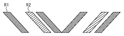
図6Aは、色ずれを検知するためのパッチの一例を示す図である。色ずれ検知用のパッチの画像データも、パターンジェネレータ430が生成する。図6Aが示すように、パッチは、基準色であるイエローYのパターンR1とその他の色(図ではマゼンタM)のパターンR2とからなる。パッチ検知センサ80によって、パターンR1とR2との距離を測定することで、CPU301は、基準色に対するずれ量を測定できる。
<Color shift detection>
FIG. 6A is a diagram illustrating an example of a patch for detecting color misregistration. The
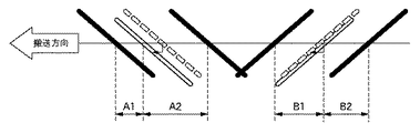
図6Bは、基準色であるY色に対するずれ量を求める方法の一例を説明するための図である。図6Bが示すように、パッチ検知センサ80は、形成されたレジストパターンを読み取ることで、距離A1、A2、B1、B2を検出する。Y色に対する主走査方向のずれ量△H、副走査方向のずれ量△Vは、次式により表現される。
FIG. 6B is a diagram for explaining an example of a method for obtaining a deviation amount with respect to the Y color as the reference color. As shown in FIG. 6B, the
△H={(B2−B1)/2−(A2−A1)/2}/2
△V={(B2−B1)/2+(A2−A1)/2}/2
本実施形態では、累積して100ページ以上が形成されるごとにパッチが形成され、主走査方向のずれ量△H、副走査方向のずれ量△Vが算出される。
ΔH = {(B2-B1) / 2- (A2-A1) / 2} / 2
ΔV = {(B2-B1) / 2 + (A2-A1) / 2} / 2
In the present embodiment, the patches are formed each time it is accumulated over 100 pages and is formed, the main scanning direction of the shift amount △ H, sub-scanning direction shift amount △ V is calculated.
<色ずれ検知用のパッチを使った画像形成位置の補正>
色ずれが検知されると、色ずれ補正処理が実行される。すなわち、基準色の感光体と補正対象色の感光体との間隔に応じた描画タイミング遅延量と、主走査書出位置センサ503からの検出信号の出力タイミングに対する描画タイミング遅延量とは、色ずれが解消されるよう補正される。
<Correction of image forming position using patch for color misregistration detection>
When color misregistration is detected, color misregistration correction processing is executed. That is, the drawing timing delay amount corresponding to the interval between the reference color photoconductor and the correction target color photoconductor and the drawing timing delay amount with respect to the output timing of the detection signal from the main scanning
図7は、プリントページエリアと各信号との関係を示した図である。ここでは、主走査方向をX軸とし、副走査方向をY軸としている。プリントページエリア700は、主走査幅Wm、副走査幅Wsの矩形をしている。BDは、主走査書出位置センサ503の検出信号を示している。startは、描画開始位置信号を示している。Emは、主走査方向における有効画像域を表す信号である。Esは、副走査方向における有効画像域を表す信号である。Lmは、BD信号の立ち上がり位置から主走査方向における描画位置基準までの距離(遅延時間)である。Lsは、start信号の立ち上がり位置から副走査方向における描画位置基準までの距離(遅延時間)である。例えば、主走査方向のずれ量は、Lmに対して反映される。なお、以下で説明するように、Lsは、YMCKの色毎に異なる。
FIG. 7 is a diagram showing the relationship between the print page area and each signal. Here, the main scanning direction is the X axis and the sub scanning direction is the Y axis. The
図8は、YMCK各色の感光体21と中間転写ベルト22との関係を示す図である。MCKの各Lsは、それぞれ図中のm0、c0、k0の距離を中間転写ベルト22の周速度で除算して得られる時間に相当する。この図では、Y色の描画タイミングを基準として、それぞれに相当した遅延時間が経過したときに各色の描画開始位置信号が出力される。副走査方向のずれ量は、Lsに反映される。描画開始位置信号であるstartは、CPU311の指示に伴い、デバイス制御部314が発行する。
FIG. 8 is a diagram showing the relationship between the
<潜像形成における副走査方向の湾曲補正>
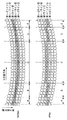
図9は、走査線が副走査方向に湾曲した例と、湾曲を補正した例を示す図である。とりわけ、図9の上側には、湾曲補正を行わない場合における隣接した5本の走査線の軌跡と各画素の関係が示されている。走査線を示す円のそれぞれは、画素の描画位置を示している。なお、斜線の付された円は、画像データ上における同一ラインの画素を示している。なお、走査線とは、感光体上における光ビームの軌跡のことである。ラインとは、画像データにおける副走査位置が同一の画素群のことである。
<Curve correction in the sub-scanning direction in latent image formation>
FIG. 9 is a diagram illustrating an example in which the scanning line is curved in the sub-scanning direction and an example in which the curvature is corrected. In particular, the upper side of FIG. 9 shows the relationship between the trajectory of five adjacent scanning lines and each pixel when the curvature correction is not performed. Each of the circles indicating the scanning lines indicates a pixel drawing position. Note that the hatched circles indicate pixels on the same line on the image data. A scanning line is a locus of a light beam on the photosensitive member. A line is a group of pixels having the same sub-scanning position in image data.
図9の下側には、湾曲補正が行われたときの隣接した5本の走査線の軌跡と各画素の関係が示されている。湾曲補正では、主走査方向における複数の適切な位置(乗り換え点)で、注目画素のデータを元の走査線に隣接した他の走査線によって描くようデータの入れ替え(走査線の乗り換え)を行う。例えば、B区間、D区間では補正量が0である。A区間、E区間では画素のデータを下方向に1画素シフトされている。C区間では、画素のデータが上方向に1画素シフトされている。これにより、形成された画像では、斜線の付された円の集合である注目ラインが略直線となる。 The lower side of FIG. 9 shows the relationship between the trajectories of five adjacent scanning lines and the respective pixels when the curvature correction is performed. In the curvature correction, data replacement (scan line change) is performed so that the data of the pixel of interest is drawn by another scan line adjacent to the original scan line at a plurality of appropriate positions (transfer points) in the main scanning direction. For example, the correction amount is 0 in the B section and the D section. In the A section and the E section, the pixel data is shifted downward by one pixel. In section C, pixel data is shifted upward by one pixel. As a result, in the formed image, the target line, which is a set of hatched circles, is a substantially straight line.
単純な湾曲補正を適用しただけでは、1画素の段差が発生してしまう。そこで、この段差を目立ちにくくするため、段差(乗り換え点)付近に存在する注目画素に対して副走査方向で隣接した隣接画素の濃度データと注目画素の濃度データとを中間調演算するものである。これをブレンド処理と呼ぶ。 If only simple curvature correction is applied, a step of one pixel is generated. Therefore, in order to make this step inconspicuous, halftone calculation is performed on the density data of the adjacent pixel adjacent to the target pixel existing in the vicinity of the step (transfer point) in the sub-scanning direction and the density data of the target pixel. . This is called blend processing.
図10は、実施形態に係る湾曲補正処理部の例示的なブロック図である。上述したように、湾曲補正処理部552は、画像処理部407に存在する。
FIG. 10 is an exemplary block diagram of a curvature correction processing unit according to the embodiment. As described above, the curvature
Vin1は、ガンマ補正部406から供給されたビデオ入力信号であり、レーザ発光パターンと同等の画像データである。Vin1は、4bitの信号線束により実現されている。Vin2は、パターンジェネレータ430から供給されたビデオ入力信号であり、レーザ発光パターンと同等の画像データである。Vin2も、4bitの信号線束により実現されている。HSYNCは、主走査同期信号である。主走査書出位置センサ503からBD信号が出力されたタイミングでCPU301から出力される。ガンマ補正部406やパターンジェネレータ430から画像データを取得するタイミングとして利用される。HSYNCは、動作同期を取るため、各部に分配される。selectは、入力された複数のビデオ入力信号のうち出力すべきビデオ入力信号を選択するための選択信号であり、CPU301から供給される。
Vin1 is a video input signal supplied from the
湾曲補正データ保持部1001は、CPU301から通信信号COMにより伝送されてきた湾曲補正データを保持する。湾曲補正データは、例えば、HSYNC(BD)からの距離Lmを表す距離データと、補正量を表す補正量データ(例:1〜7ライン)とをデータセットペアとしている。例えば、湾曲補正データ保持部1001には、最大で32ペアの湾曲補正データが保持される。
The curvature correction
Trefは、湾曲補正データ保持部1001から供給される基準湾曲補正タイミング信号である。ブレンド比計算部1002は、ブレンド処理の適用対象となって各画素に適用されるブレンド比を算出して出力する。BRは、算出されたブレンド比を表すブレンド比データ信号である。
Tref is a reference curve correction timing signal supplied from the curve correction
湾曲補正データ用ラインバッファ1003は、1走査分の湾曲補正タイミング信号を保持するバッファである。ブレンド比データ用ラインバッファ1004は、1走査分のブレンド比データを保持するバッファである。画像データ用ラインバッファ1005は、画像データ保持部551から出力された7ラインのビデオ入力信号(画像データ)を保持するバッファである。
The curve correction
ブレンド演算部1006は、画像データ用ラインバッファ1005から7ラインの画像データのうち、湾曲補正データに基づいて取り出すラインを選択する7to1セレクタとして機能する。また、ブレンド演算部1006は、副走査方向における隣接画素のデータを参照して現在走査対象となって画素のデータをブレンド演算する機能を備えている。例えば、ブレンド演算部1006は、乗り換え点付近に存在する注目画素の濃度と、注目画素の副走査方向において隣接した1つ以上の隣接画素の濃度とを注目画素からの距離に応じた重み付けにより変更する重み付け処理部として機能する。また、ブレンド演算部1006は、注目画素と、1つ以上の隣接画素のうち第1色に対する第2色の色ズレの原因となっている隣接画素とに重み付け処理を実行するように構成されてもよい。Voutは、レーザPWM部560へ出力される湾曲補正後の画像データであり、4bitビデオデータ信号である。
The
湾曲補正処理部552は、画像クロックに同期して動作する画像クロック同期回路であり、1画像クロックに1ステップずつ処理を実行する。主走査1ライン分の処理は、HSYNCにしたがって開始される。HSYNCは、10000画像クロック程度の周期を有する。次のHSYNCが入力されると、次のラインが処理対象となる。ビデオ入力信号Vin1、Vin2として入力される画像データは、主走査方向及び副走査方向ともに600dpiの解像度である。1画素の画像データは、4bitで表現される。すなわち、16段階の濃度データとなっている。これは、レーザPWM部560における発光時間が16段階であることを意味する。
The curvature
<ブレンドデータの発生>
作像動作前に、CPU301は、通信信号COMを通じて初期データを湾曲補正データ保持部1001に書き込む。初期データは、書き込み光学ユニットの製造時の検査工程において2次元CCDを備えた測定冶具によって走査線の湾曲状態を測定した結果を基に決定される。
<Generation of blend data>
Prior to the image forming operation, the
画像データ用ラインバッファ1005に備えられるラインバッファの本数は、光学設計上の誤差見積りに応じて決定される。すなわち、光学設計上の誤差見積りから、湾曲補正量が7ライン以下と見積もられるためである。Vin1やVin2から入力された画像データは、7つあるラインバッファのうち1番目のラインバッファから順に書き込まれる。HSYNCが発生するたびに、書き込まれるラインバッファが次の(下の)ラインバッファへと切り替えられる。最終的に、7番目のラインバッファまで書き込まれると、再び、1番目のラインバッファに書き込まれる。1番目のラインバッファでは、データが上書きされる。このように、画像データ用ラインバッファ1005は、巡回書込を実行する。
The number of line buffers provided in the image
先端の余白に相当する7ライン分の画像データが受信されると、ブレンド演算部1006は、湾曲補正を実現するためのデータシフト(走査線の乗り換え)を開始する。湾曲補正が実行されない初期状態では、ブレンド演算部1006は、7つあるラインバッファのうち、ニュートラルである3番のラインを格納しているラインバッファを選択する。何番目のラインバッファを選択するかの指示は、湾曲補正データ保持部1001から出力されるTrefに含まれている。初期状態では、湾曲補正タイミング信号Trefは、非アクティブという指示が含まれている。また、ブレンド比データBRは、ブレンド比がゼロであることを示している。なお、画像データ用ラインバッファ1005は、巡回書込方式を採用しているため、ニュートラルである3番のラインを格納しているラインバッファは、必ずしも上から3番目のラインバッファではない。ニュートラルのラインを格納しているラインバッファは、最新のラインのデータが書き込まれたラインバッファから数えて3番目のラインバッファとなる。
When image data for seven lines corresponding to the margin at the tip is received, the
図11は、湾曲補正処理部でのデータフローのタイミングチャートである。HSYNCは、水平同期信号である。ICLKは、画像クロックを示す。画像クロックは、図中の横1マスが1クロック時間に相当する。COUNTは、湾曲補正データ保持部1001における主走査方向の画素位置をカウントするカウンタのカウンタ値である。基準湾曲補正タイミング信号Trefは、ACC0とDEC0といった2つ信号を含んでいる。ACC0は、上方向にラインを乗り換えること意味する信号である。DEC0は、下方向にラインを乗り換えることを意味する信号である。BRは、上述したブレンド比データである。
FIG. 11 is a timing chart of the data flow in the curvature correction processing unit. HSYNC is a horizontal synchronization signal. ICLK indicates an image clock. In the image clock, one horizontal cell in the figure corresponds to one clock time. COUNT is a counter value of a counter that counts pixel positions in the main scanning direction in the curvature correction
湾曲補正データ保持部1001は、主走査方向における現在の画素位置をカウントするカウンタを備えている。カウンタは、HSYNCが入力されると初期化(クリア)される。入力された画素距離データとカウンタのカウント値が一致すると、湾曲補正データ保持部1001は、基準湾曲補正タイミング信号Trefを1画像クロックにわたりアクティブにする。基準湾曲補正タイミング信号Trefに含まれるACC0とDEC0によって、湾曲補正データの副走査方向における移動方向(+1,−1)が示される。また、湾曲補正データの主走査位置がパルスの発生タイミングとして表現される。
The curvature correction
ブレンド比計算部1002は、受信したTrefのACC0及びDEC0にしたがって、段差が目立ちにくくなるようブレンド比データBRを算出する。さらに、ブレンド比計算部1002は、画像クロックが進むにつれてブレンド比を変化させてゆく。これは、注目画素と隣接画素との距離に応じて濃度に重み付けするためである。BRは、BLD3〜BLD0といったの4つ信号により伝送される。すなわち、BLD3〜BLD0は、ACC0,DEC0により示された移動方向に対するブレンド比とそのブレンドが適用される主走査方向の位置(タイミング)を示す。
The blend
例えば、1つの画像クロックにつき1/16ずつブレンド比が増加するものと仮定する。よって、8つの画像クロックが入力された時点では、8*(1/16)=50%のブレンド比となる。15個の画像クロックが入力された時点では、15*(1/16)=約94%のブレンド比となる。ただし、最後の1画像クロックが入力された時点では、ブレンド比が16*(1/16)=100%にはならず、0*(1/16)=0%に戻る。 For example, assume that the blend ratio increases by 1/16 per image clock. Therefore, when 8 image clocks are input, the blend ratio is 8 * (1/16) = 50%. When 15 image clocks are input, the blend ratio is 15 * (1/16) = about 94%. However, when the last one image clock is input, the blend ratio does not become 16 * (1/16) = 100% but returns to 0 * (1/16) = 0%.
ここで、湾曲補正タイミング信号Trefは、入力された画像データ(Vin1)に同期して湾曲補正データ用ラインバッファ1003に書き込まれる。同様に、ブレンド比データBRも入力された画像データ(Vin1)に同期してブレンド比データ用ラインバッファ1004に書き込まれる。
Here, the curvature correction timing signal Tref is written in the curvature correction
<ブレンド演算>
図12は、ブレンド演算部1006での入出力データの一例を示した図である。HSYNCに同期して、湾曲補正データ用ラインバッファ1003、ブレンド比データ用ラインバッファ1004及び画像データ用ラインバッファ1005からデータが読み出される。
<Blend operation>
FIG. 12 is a diagram illustrating an example of input / output data in the
cnは、画像データ用ラインバッファ1005のうち、3番目のラインバッファから出力される信号である(nは添え字)。dnは、4番目のラインバッファから出力される信号である。enは、5番目のラインバッファから出力される信号である。xnは、湾曲補正がなされたデータであり、上述したVoutである。Selは、ブレンド演算部1006においてどのラインバッファを選択したかを示す信号である。例えば、sel(3,4)は、画像データ用ラインバッファ1005のうち、3番目と4番目のラインバッファが選択されていることを示している。
cn is a signal output from the third line buffer of the image data line buffer 1005 (n is a subscript). dn is a signal output from the fourth line buffer. en is a signal output from the fifth line buffer. xn is data subjected to curvature correction, and is Vout described above. Sel is a signal indicating which line buffer has been selected in the
ブレンド演算部1006のシフタ機能(走査線の乗り換え機能)は、画像データ用ラインバッファ1005から読み出すべきラインを3、4番に設定する。さらに、ブレンド演算部1006は、ブレンド比データに従って、読み出したラインの画素データに対してブレンド演算を実行する。次に、ブレンド演算部1006は、湾曲補正データに従って、読み出すべきラインを4、5番へ切り替える。このラインの切り替えと同時にブレンド比は0%に戻るため、1ラインのシフトが完了したことになる。すなわち、非ブレンド状態の3、4番保持から、非ブレンド状態の4、5番保持へ切り替わったことになる。
The shifter function (scan line changing function) of the
出力される画像データVoutとしては、まず3番ライン(非ブレンド状態)の画素データが出力される。次のクロックで、4番ラインの画素データに1/16を重み付けし、3番ラインの画素データに15/16を重み付けしてこれらを加算して得られた和のデータがVoutとして出力される。さらに次のクロックで、4番ラインの画素データに2/16を重み付けし、3番ラインの画素データに14/16を重み付けしてこれらを加算して得られた和のデータがVoutとして出力される。以降では、画像クロックが1つ進むたびに、出力されるデーは、1/16ずつ4番ラインのデータに近づいてゆく(3番ラインのデータから遠ざかってゆく)。例えば、8個目の画像クロックが入力された時点では、3番ラインからの画素データと、4番ラインからの画素データとが50%づつ加算して得られたデータがVoutとして出力される。15個目の画像クロックが入力された時点では、出力されるデータのうち、15/16が4番ラインからのデータで、1/16が3番ラインからのデータとなる。さらに次の画像クロックが入力された時点は、4番ラインからの画素データのみが、Voutとして出力される(非ブレンド状態)。 As the output image data Vout, pixel data of the third line (unblended state) is output first. At the next clock, the sum data obtained by adding 1/16 to the pixel data of the 4th line and adding 15/16 to the pixel data of the 3rd line is output as Vout. . In the next clock, the pixel data of the 4th line is weighted by 2/16, the pixel data of the 3rd line is weighted by 14/16, and the sum is obtained as Vout. The Thereafter, every time the image clock advances by 1, the output data approaches 1st line data by 1/16 (moves away from the 3rd line data). For example, when the eighth image clock is input, data obtained by adding pixel data from the third line and pixel data from the fourth line by 50% is output as Vout. At the time when the fifteenth image clock is input, 15/16 of the output data is data from the 4th line and 1/16 is data from the 3rd line. Furthermore, when the next image clock is input, only pixel data from the 4th line is output as Vout (non-blended state).
Voutは、次のようになる。 Vout is as follows.
xn=cn (n<2、18≦n、次のブレンド部を除く)
xn={cn*(18−n)+dn*(n−2)}/16 (2≦n<18)
図12に示した現在の描画ラインのデータを、x3,c3,d3,e3とする。ここで、c,dは、主走査位置は同一であるが、それぞれ1ライン前と現在のラインの画像データであることを示している。d、eは、主走査位置は同一であるが、それぞれ現在のラインと1つ後のラインの画像データであることを示している。x3,c3,d3,e3における数字の1、2、3、4は、それぞれのラインで主走査方向における順番を示している。
xn = cn (n <2, 18 ≦ n, excluding the next blend part)
xn = {cn * (18−n) + dn * (n−2)} / 16 (2 ≦ n <18)
The current drawing line data shown in FIG. 12 is assumed to be x3, c3, d3, e3. Here, c and d indicate that the main scanning position is the same, but that the image data is the previous line and the current line, respectively. d and e indicate that the main scanning position is the same, but that the image data is the current line and the next line.
Voutの内訳であるx1、x2、x3、x4は、湾曲補正された現レーザ描画ラインの画像データである。ここで基準となる湾曲補正位置(乗り換え点)は、ブレンド比で8/16となる位置である。 The breakdowns of Vout, x1, x2, x3, and x4, are image data of the current laser drawing line whose curvature has been corrected. Here, the reference curvature correction position (transfer point) is a position where the blend ratio is 8/16.
上記では演算処理をミクロな視点から説明をした。本発明の概念をさらにわかりやすくするため、複数点で湾曲補正を行った例を以下に示す。 In the above, the arithmetic processing has been described from a microscopic viewpoint. In order to make the concept of the present invention easier to understand, an example in which curvature correction is performed at a plurality of points is shown below.
<ブレンド処理結果>
図13は、元となる画像データの配列を示す図である。画像データをわかりやすくするために、各画素には濃度に対応した配色(白又は斜線)が付与されている。図14は、図13に示した画像データを、湾曲補正せずに画像形成した例を示す図である。図14が示すように、副走査方向に湾曲が現れていることを理解できよう。
<Blend processing result>
FIG. 13 is a diagram showing an array of original image data. In order to make the image data easy to understand, each pixel is given a color scheme (white or slanted line) corresponding to the density. FIG. 14 is a diagram showing an example in which the image data shown in FIG. 13 is formed without correcting the curvature. As shown in FIG. 14, it can be understood that a curve appears in the sub-scanning direction.
図15は、図13に示した画像データを、湾曲補正を適用するもののブレンド処理を適用していない画像データの一例を示す図である。乗り換え点の付近で段差が生じていることを確認できよう。図16は、図15に示した画像データを用いて形成された画像の一例を示す図である。図16が示すように、湾曲が緩和されていることを視認できよう。ただし、依然として、補正段差が目立っていることも視認できよう。図17は、図15に示した画像データに対してさらにブレンド処理も適用して形成された画像の一例を示す図である。 FIG. 15 is a diagram illustrating an example of image data to which the curvature correction is applied but the blending process is not applied to the image data illustrated in FIG. 13. You can see that there is a step near the transfer point. FIG. 16 is a diagram showing an example of an image formed using the image data shown in FIG. As FIG. 16 shows, it can be visually recognized that the bending is relaxed. However, it can still be seen that the correction step is conspicuous. FIG. 17 is a diagram showing an example of an image formed by further applying a blend process to the image data shown in FIG.
このように、本実施形態では、第1色の走査線の湾曲を補正するために画像データにおける注目ラインの画素の一部を隣接したラインの画素へと乗り換えさせる湾曲補正処理が適用される。さらに、本実施形態では、画素の乗り換え点付近に存在する複数の画素の濃度を調整することで、乗り換え点に生じた段差を緩和するブレンド処理も適用される。その結果、湾曲を緩和しつつ、補正段差も目立ちにくくなる。 Thus, in this embodiment, in order to correct the curve of the scanning line of the first color, a curve correction process is applied in which a part of the pixel of the target line in the image data is changed to the pixel of the adjacent line. Furthermore, in this embodiment, a blending process is also applied in which the steps generated at the transfer point are alleviated by adjusting the densities of a plurality of pixels existing in the vicinity of the pixel transfer point. As a result, the correction step becomes less conspicuous while relaxing the curvature.
<色ずれ補正>
以下では、第1色のラインに対して重ねて形成される第2色のラインについて乗り換え点付近の太さが太くなるよう乗り換え点付近の画素のデータを変更する色ずれ補正処理について説明する。例えば、乗り換え点付近に存在する画素のデータの濃度を増強したり、当該画素のサイズ(光ビームのスポット径)を拡大したりすることで、色ずれが緩和される。上述した画像処理部407は、乗り換え点付近に存在する画素のサイズを通常のサイズより拡大する拡大処理部の一例である。上述したレーザPWM部560は、画素を形成するための光ビームのスポット径を拡大させるよう光源の駆動電流を増加させる駆動電流制御部の一例である。
<Color shift correction>
In the following, a description will be given of color misregistration correction processing for changing data of pixels near a transfer point so that the thickness of the second color line formed to overlap the first color line becomes thicker. For example, the color misregistration is alleviated by increasing the density of data of pixels existing near the transfer point or by enlarging the size of the pixel (spot diameter of the light beam). The above-described
以下では、このような色ずれ補正を「2色目補助ブレンド処理」と呼ぶことにする。1色目と2色目とでは、湾曲補正処理におけるTrefと、ブレンド比計算部1002の出力値が異なる。
Hereinafter, such color misregistration correction is referred to as “second color auxiliary blend processing”. The first color and the second color differ in Tref in the curvature correction processing and the output value of the blend
2色目に関して、基準湾曲補正タイミング信号Trefには、補助信号ACC2, DEC2といった2つの信号が含まれる。これにより、1色目のブレンド処理が適用された画素の位置や移動方向の情報が伝達される。このような1色目のブレンド処理に関する情報にしたがって、2色目も薄いブレンド処理が施されるようブレンド比が決定される。 For the second color, the reference curvature correction timing signal Tref includes two signals such as auxiliary signals ACC2 and DEC2. Thereby, information on the position and moving direction of the pixel to which the blend process of the first color is applied is transmitted. In accordance with such information regarding the blend process for the first color, the blend ratio is determined so that the blend process for the second color is thin.
<補助ブレンドデータ>
図18は、湾曲補正処理部における補助ブレンドデータフローを示すタイミングチャートである。すでに説明した信号には、同一の名称を付与している。ICLKは、画像クロックであり、図の横方向に示した1マスはクロック同期回路の1クロック時間に相当する。COUNTは、湾曲補正データ保持部1001におけるの主走査画素位置をカウントするカウンタ値である。ACC2, DEC2は、それぞれ基準湾曲補正タイミング信号Trefに含まれている2つの信号である。ACC2は上方向への乗り換えを示し、DEC2は下方向への乗り換えを示す。BRは、湾曲補正ブレンド比データである。
<Auxiliary blend data>
FIG. 18 is a timing chart showing the auxiliary blend data flow in the curvature correction processing unit. The signals already described are given the same names. ICLK is an image clock, and one square shown in the horizontal direction in the figure corresponds to one clock time of the clock synchronization circuit. COUNT is a counter value that counts main scanning pixel positions in the curvature correction
1色目と2色目とでは、ブレンド比データBRの内容が異なる。基準湾曲補正タイミング信号Trefを受けると、ブレンド比計算部1002はTrefの内容に従い、ブレンド比データBRを発生させ、画像クロックICLKの進みにつれてブレンド比を徐々に変化させてゆく。BRは、BLD3〜BLD0といったの4つ信号により伝送される。BLD3〜BLD0は、ACC2,DEC2によって示された補正方向に対するブレンド比とそのブレンドタイミングを示す。ここで1画像クロックにつき1/32ずつブレンド比が増加するブレンド比傾斜であったとすると、8画像クロック経過で8/32=25%のブレンド比となる。補助ブレンドでは、25%の時点からブレンド比が低下方向に切りわる。計15画像クロック経過で1/32のブレンド比となる。次の1クロックでブレンド比が0/32=0%に戻る。
The content of the blend ratio data BR differs between the first color and the second color. When the reference curve correction timing signal Tref is received, the blend
ここで、湾曲補正タイミング信号Trefは、入力画像データに同期して湾曲補正データ用ラインバッファ1003に書き込まれ、湾曲補正ブレンド比データBRは同様にブレンド比データ用ラインバッファ1004に書き込まれる。
Here, the curvature correction timing signal Tref is written in the curvature correction
<補助ブレンド演算処理>
図19は、実施形態に係るブレンド演算部1006での入出力データの一例を示すタイミングチャートである。各信号の名称はすでに説明したとおりである。1色目と2色目とでは、選択されるラインバッファが異なる。すなわち、図中のSelが示す内容が異なる。例えば、ACC2に応じてSelの変更が終始おこらない。一方で、DEC2に応じた最初の位置で、Selの変更が発生する。すなわち、DEC2がアクティブになる前は、sel(3、4)であったものが、DEC2がアクティブになると、sel(5、4)に変更される。また補助ブレンドが終了すると、Selは、元のsel(3、4)に戻る。
<Auxiliary blend calculation processing>
FIG. 19 is a timing chart illustrating an example of input / output data in the
ブレンド演算部1006の内部に設けられたシフタ機能は、画像データ用ラインバッファ1005のうち読み出すべきラインバッファを3番目と、4番目とに維持する。3番目と4番目のラインバッファから出力されたデータに従って、ブレンド演算部1006は、ブレンド演算を実行する。最終的に、ブレンド比は0%に戻るため、2色目の補助ブレンドでは、1ラインもシフトせず、非ブレンド状態が維持される。
Shifter function provided in the interior of the
画像データの出力信号であるxnは、当初、3番目のラインバッファからの出力の非ブレンド状態である。次のクロックでxnは、1/32が4番目のラインバッファからのデータであり、15/32が3番目のラインバッファからのデータである。すなわち、xnは、ブレンド状態となる。その次のクロックからさらに1/32ずつ、徐々に4番目のラインバッファからのデータにxnは近づいてゆく。そして8クロック目で、3、4番のラインバッファからのデータがそれぞれ25%ずつxnに含まれる状態となる。その後、15クロック目で、xnは、1/16が4番目のラインバッファからのデータとなり、15/16が3番目のラインバッファからのデータとなる。次のクロックで、3番目のラインバッファからのデータのみとなる(非ブレンド状態)。このようにブレンドされた結果、xnは、次のようになる。 An output signal xn of image data is initially in an unblended state of the output from the third line buffer. In the next clock xn, 1/32 is the data from the fourth line buffer and 15/32 is the data from the third line buffer. That is, xn is in a blended state. Xn gradually approaches the data from the fourth line buffer in increments of 1/32 from the next clock. Then, at the eighth clock, data from the third and fourth line buffers is included in xn by 25% each. Thereafter, at the 15th clock, 1/16 of the xn becomes data from the fourth line buffer, and 15/16 becomes data from the third line buffer. At the next clock, only data from the third line buffer is present (unblended state). As a result of such blending, xn is as follows.
xn=cn (n<2、18≦n、次のブレンド部を除く)
xn={cn*(34−n)+dn*(n−2)}/32 (2≦n<10)
xn={cn*(14+n)+dn*(18−n)}/32 (10≦n<18)
<2色目補助ブレンド処理の効果>
図20は、2色目の細線(直線)を1色目のラインに単純に重ねることで1色目と2色目の中間色で細線を描画した比較例を示す図である。左辺第1項C1が1色目の画像であり、走査線の乗り換えによる湾曲補正とブレンド処理が適用さされている。円のサイズは、ブレンド処理による画素の濃度比率を示している。左辺第2項C2が2色目の画像である。2色目に関しては、走査線の湾曲が小さいため、画素が一列に並んでいる。右辺C3が、重ね合わせ画像を示している。
xn = cn (n <2, 18 ≦ n, excluding the next blend part)
xn = {cn * (34−n) + dn * (n−2)} / 32 (2 ≦ n <10)
xn = {cn * (14 + n) + dn * (18−n)} / 32 (10 ≦ n <18)
<Effect of second color auxiliary blend processing>
FIG. 20 is a diagram illustrating a comparative example in which a thin line is drawn with an intermediate color between the first color and the second color by simply superimposing the second color thin line (straight line) on the first color line. The first term C1 on the left side is an image of the first color, and curvature correction and blending processing by changing scanning lines are applied. The size of the circle indicates the pixel density ratio by the blending process. The second term C2 on the left side is the second color image. With respect to the second color, since the scan line is small in curvature, the pixels are arranged in a line. The right side C3 shows the superimposed image.
パッチにより得られた色ずれ量にしたがって、1色目の細線と2色目の細線の各重心がほぼ重なるように制御される。しかし、乗り換え点付近における1色目の細線のライン幅は2ラインであるが、2色目の細線のライン幅は1ラインである。したがって、重ね合わせ画像では、最大色ずれ比が2:1となるため、色ずれが視認されやすくなる。 In accordance with the color misregistration amount obtained by the patch, control is performed so that the centroids of the first color fine line and the second color fine line substantially overlap. However, the line width of the thin line of the first color in the vicinity of the transfer point is 2 lines, but the line width of the thin line of the second color is 1 line. Therefore, since the maximum color misregistration ratio is 2: 1 in the superimposed image, the color misregistration is easily visible.
図21は、実施形態に係る2色目補助ブレンド処理を適用した2色目の細線(直線)を1色目のラインに重ねることで1色目と2色目の中間色で細線を描画した例を示す図である。2色目の細線が3ライン幅に拡大されているため、最大色ずれ比が2:3となっている。これにより、色ずれが相対的に認識されにくくなる。 FIG. 21 is a diagram illustrating an example in which a thin line is drawn with an intermediate color of the first color and the second color by superimposing a thin line (straight line) of the second color to which the second color auxiliary blending process according to the embodiment is applied on the first color line. . Since the thin line of the second color is expanded to a width of 3 lines, the maximum color shift ratio is 2: 3. As a result, color misregistration is relatively difficult to be recognized.
比較例の色ずれ量は2ライン−1ライン=1ラインであり、実施形態に係る色ずれ量も3ライン−2ライン=1ラインであり、両者は変わらない。しかし、2色目における3つのラインのうち、上位ラインと下位ラインの画素の濃度は、1色目のブレンド処理された画素の濃度よりも低く制御されている。すなわち、円のサイズがより小さくなっている。それゆえ、本実施形態は、比較例よりも際立って色ずれがわかりにくくなる。 The color misregistration amount of the comparative example is 2 lines-1 line = 1 line, and the color misregistration amount according to the embodiment is 3 lines-2 lines = 1 line. However, among the three lines in the second color, the density of the pixels of the upper line and the lower line is controlled to be lower than the density of the pixel subjected to the blend process of the first color. That is, the size of the circle is smaller. Therefore, in the present embodiment, the color misregistration is significantly more difficult to understand than the comparative example.
[第2の実施形態]
<補助増強処理>
第1の実施形態では、2色目補助ブレンド処理によって、2色目は上位及び下位ラインにそれぞれ最大で25%ずつのブレンド処理がなされた。第2の実施形態では、2色目における1画素の濃度を通常よりも増大することで、2色目補助ブレンド処理を実現する。濃度を増大するには、感光体上に形成される光ビームのスポット径を拡大させればよい。スポット径を拡大させるには、露光時間を長くする方法と、駆動電流を増大する方法とがある。なお、本実施形態では、半導体レーザ素子501が形成できる光ビームのスポット径が上限に達していないこと(すなわち、スポット径を拡大可能であること)を前提としている。第2の実施形態に係る2色目補助ブレンド処理を、以下、補助増加と呼ぶ。
[Second Embodiment]
<Auxiliary enhancement processing>
In the first embodiment, by the second color auxiliary blend process, the second color is subjected to a blend process of 25% at the maximum on the upper and lower lines. In the second embodiment, the second color auxiliary blending process is realized by increasing the density of one pixel in the second color more than usual. In order to increase the density, the spot diameter of the light beam formed on the photoreceptor may be increased. In order to enlarge the spot diameter, there are a method of increasing the exposure time and a method of increasing the drive current. In the present embodiment, it is assumed that the spot diameter of the light beam that can be formed by the
第1の実施形態と比較すると、第2の実施形態では、図18に示した動作が異なる。すなわち、BRとして、ブレンド比データではなく、濃度増加比データを採用することになる。第2の実施形態に係るVoutは以下のようになる。 Compared with the first embodiment, the operation shown in FIG. 18 is different in the second embodiment. That is, not the blend ratio data but the density increase ratio data is adopted as BR. Vout according to the second embodiment is as follows.
xn=cn (n<2、18≦n、次のブレンド部を除く)
xn=cn*{32+(n−2)}/32 (2≦n<10)
xn=cn*{32+(18−n)}/32 (10≦n<18)
なお、第2の実施形態では、図19に示した2色目の動作に関してラインバッファの選択内容は同じである。第2の実施形態では、例えば、増強比を25%に設定することで、2色目のライン幅は最大で1.25ライン幅相当となる。
xn = cn (n <2, 18 ≦ n, excluding the next blend part)
xn = cn * {32+ (n−2)} / 32 (2 ≦ n <10)
xn = cn * {32+ (18−n)} / 32 (10 ≦ n <18)
In the second embodiment, the selection contents of the line buffer are the same for the operation of the second color shown in FIG. In the second embodiment, for example, by setting the enhancement ratio to 25%, the line width of the second color is equivalent to a maximum of 1.25 line width.
図22は、実施形態に係る2色目補助ブレンド処理を適用した2色目の細線(直線)を1色目のラインに重ねることで1色目と2色目の中間色で細線を描画した例を示す図である。図22によれば、2乗り換え点付近における画素のサイズが拡大されている(濃度が増強されている)ことを理解できよう。重ね合わせ画像における最大色ずれ比は、2:1.25となる。よって、図20に示した比較例における最大色ずれ比が2:1よりも、色ずれが軽減されることを理解できよう。 FIG. 22 is a diagram illustrating an example in which a thin line is drawn with an intermediate color of the first color and the second color by superimposing the thin line (straight line) of the second color to which the second color auxiliary blend process according to the embodiment is applied on the first color line. . It can be understood from FIG. 22 that the size of the pixel in the vicinity of the second transfer point is enlarged (the density is increased). The maximum color misregistration ratio in the superimposed image is 2: 1.25. Therefore, it can be understood that the color misregistration is reduced when the maximum color misregistration ratio in the comparative example shown in FIG.
[第3の実施形態]
<色ずれ方向の2画素を増強>
第1の実施形態では、2色目の中心ラインは、上位及び下位ラインに最大で25%ずつ補助ブレンド処理が実行された。これは、1色目と2色目の走査線が乗り換え位置(ブレンド位置)において副走査方向に50%ずれている場合に好適となる。
[Third Embodiment]
<Enhance 2 pixels in the direction of color shift>
In the first embodiment, the auxiliary blend process is executed for the center line of the second color by a maximum of 25% for the upper and lower lines. This is suitable when the scanning lines for the first color and the second color are shifted by 50% in the sub-scanning direction at the transfer position (blend position).
しかし、1色目と2色目のブレンド位置において副走査方向に25%又は75%の色ずれが発生している状態では、1色目のブレンドによって生じた段差を埋めるよう、2色目における補助ブレンドの方向が決定されることがさらに望ましい。 However, in the state where a color shift of 25% or 75% occurs in the sub-scanning direction at the blend position of the first color and the second color, the direction of the auxiliary blend in the second color so as to fill the step generated by the blend of the first color More preferably, is determined.
図23は、色ずれ量が副走査方向に25%である場合に、実施形態に係る2色目補助ブレンド処理を適用した2色目の細線(直線)を1色目のラインに重ねることで1色目と2色目の中間色で細線を描画した例を示す図である。図24は、色ずれ量が副走査方向に75%である場合に、実施形態に係る2色目補助ブレンド処理を適用した2色目の細線(直線)を1色目のラインに重ねることで1色目と2色目の中間色で細線を描画した例を示す図である。何れの場合も、最大色ずれ比が2:2となるため、色ずれが軽減されることがわかる。 FIG. 23 shows that when the color misregistration amount is 25% in the sub-scanning direction, the second color thin line (straight line) to which the second color auxiliary blend processing according to the embodiment is applied is superimposed on the first color line. It is a figure which shows the example which drawn the thin line with the intermediate color of the 2nd color. FIG. 24 shows that when the amount of color misregistration is 75% in the sub-scanning direction, the second color thin line (straight line) to which the second color auxiliary blend processing according to the embodiment is applied is superimposed on the first color line. It is a figure which shows the example which drawn the thin line with the intermediate color of the 2nd color. In any case, since the maximum color misregistration ratio is 2: 2, it can be seen that the color misregistration is reduced.
[他の実施形態]
<上中下の3画素または上下2画素をブレンド処理する場合>
上述した実施形態によれば、初期状態の色ずれ量が50%である場合を中心に説明したが、本発明はこのような特定の数値にのみ限定されるわけではない。例えば、さらに以下で説明するよう複数の代替方法が採用されてもよい。
[Other Embodiments]
<When blending the upper, middle, and lower 3 pixels or the upper and lower 2 pixels>
According to the above-described embodiment, the case where the color misregistration amount in the initial state is 50% has been mainly described, but the present invention is not limited only to such specific numerical values. For example, a plurality of alternative methods may be employed as described further below.
例えば、調整後色ずれ状態(方向、量)に依存せずに、2色目補助ブレンド処理として、副走査方向における上中下の3画素に対して、第1乃至第3の実施形態で説明した何れかのブレンド処理が適用されてもよい。また、2色目補助ブレンド処理として、副走査方向における上中下の3画素のうちの2画素又は中央の1画素に、第1乃至第3の実施形態で説明した何れかのブレンド処理が適用されてもよい。 For example, the first to third embodiments described the upper, middle, and lower three pixels in the sub-scanning direction as the second-color auxiliary blend process without depending on the post-adjustment color misregistration state (direction and amount). Any blending process may be applied. In addition, as the second color auxiliary blending process, any one of the blending processes described in the first to third embodiments is applied to two of the upper, middle, and lower three pixels in the sub-scanning direction or one central pixel. May be.
とりわけ、補助的な増強が適用されたデータは、例えば、以下の式により表現される。 In particular, the data to which the auxiliary enhancement is applied is expressed by the following equation, for example.
xn=cn (n<2、18≦n、次のブレンド部を除く)
xn=cn+{dn*(n−2)}/32 (2≦n<10)
xn=cn+{dn*(18−n)}/32 (10≦n<18)
色ずれの調整が完了した状態(ブレンドの方向及び量)に合わせて、2色目の補助ブレンドが実行されてもよい。すなわち、2色目の補助ブレンドでは、上中下の3画素、上中下3画素中の2画素または中央の1画素を、「補助ブレンド」または「補助増強」してもよい。
xn = cn (n <2, 18 ≦ n, excluding the next blend part)
xn = cn + {dn * (n−2)} / 32 (2 ≦ n <10)
xn = cn + {dn * (18−n)} / 32 (10 ≦ n <18)
The auxiliary blend of the second color may be executed in accordance with the state where the adjustment of color misregistration is completed (blend direction and amount). That is, in the auxiliary blend of the second color, two of the upper, middle, and lower three pixels, two of the upper, middle, and lower three pixels or one central pixel may be “auxiliary blend” or “auxiliary enhancement”.
色ずれの調整が完了した状態(ブレンドの方向及び量)と各湾曲補正点の状態に合わせて、第1乃至第3の実施形態のうちの1つ以上を適用してもよい。加えて、上中下の3画素、上中下3画素中の2画素または中央の1画素に、補助ブレンドまたは補助増強を適用してもよい。 One or more of the first to third embodiments may be applied in accordance with the state (blend direction and amount) of adjustment of color misregistration and the state of each curve correction point. In addition, auxiliary blending or auxiliary enhancement may be applied to two pixels in the upper, middle, and lower three pixels, two of the upper, middle, and lower three pixels, or a central pixel.
上述した実施形態では、隣接した2画素を補助ブレンド対象としたが、隣接距離が2画素以上離れた複数の画素についてブレンドや増強を実行してもよい。また、濃度の増強とは、細線データや文字データ等の太らせ処理と同等または類似した処理でもある。また、補助ブレンドや補助増強は、細線・文字データ領域等の文字細線領域にのみに適用されてもよい。この場合の文字細線領域は、文字細線領域を認識する認識部により特定された領域であってもよいし、プリンタデータを分析することで特定された領域であってもよい。このように、文字細線領域が認識されると、上述した乗り換え処理部、緩和処理部及び変更部をアクティブに切り替える切り替え部を設けてもよい。例えば、CPU301やMFP制御部305が認識部や切り替え部として機能してもよいし、認識部や切り替え部として機能する追加の処理回路が追加されてもよい。
In the above-described embodiment, two adjacent pixels are targeted for auxiliary blending. However, blending and enhancement may be executed for a plurality of pixels whose adjacent distances are two pixels or more. The density enhancement is a process equivalent to or similar to the thickening process for thin line data, character data, and the like. Further, auxiliary blending and auxiliary enhancement may be applied only to character thin line regions such as a thin line / character data region. The character thin line area in this case may be an area specified by a recognition unit that recognizes the character thin line area, or may be an area specified by analyzing printer data. As described above, when the character thin line region is recognized, a switching unit that switches the switching processing unit, the relaxation processing unit, and the changing unit described above to active may be provided. For example, the
補助ブレンドおよび補助増強は1色目のブレンド処理に対しての2色目の処理として説明したが、ブレンド処理が適用されない1色目に対して2色目の補助ブレンド処理が適用されてもよい。また、2色目のブレンド処理が適用された画素に対して1色目にも補助ブレンドおよび補助増強が適用されてもよい。 Although the auxiliary blending and the auxiliary enhancement have been described as the second color process for the first color blend process, the second color auxiliary blend process may be applied to the first color to which the blend process is not applied. Further, auxiliary blending and auxiliary enhancement may be applied to the first color for pixels to which the second color blending process has been applied.
Claims (7)
第1色の走査線の湾曲を補正するために画像データにおける注目ラインの画素の一部を隣接したラインの画素へとシフトするシフト処理部と、
前記注目ラインから前記隣接したラインへとシフトした画素と、シフトしなかった画素または該ラインとは異なるラインへシフトした画素との境界付近に存在する複数の画素の濃度を調整することで、該境界に生じた段差を緩和する緩和処理部と、
前記第1色のラインに対して重ねて形成される第2色のラインについて前記境界付近の太さが太くなるよう該境界付近の画素のデータを変更する変更部と
を含むことを特徴とする画像形成装置。 An image forming apparatus that scans light corresponding to image data on a rotating photoconductor, develops a latent image formed on the photoconductor with the scanned light, and transfers the developed image onto a recording sheet. There,
A shift processing unit that shifts a part of the pixels of the target line in the image data to the pixels of the adjacent line in order to correct the curvature of the scanning line of the first color;
Adjusting the density of a plurality of pixels existing in the vicinity of a boundary between a pixel shifted from the target line to the adjacent line and a pixel not shifted or a pixel shifted to a line different from the line ; A mitigation processing unit for mitigating the step formed at the boundary ;
Characterized in that it comprises a changing unit for changing the data of the pixel of the second color line near the boundary so that the thickness becomes thick in the vicinity of the boundary for that are formed overlapping the first color line Image forming apparatus.
前記境界付近に存在する注目画素の濃度と、該注目画素の副走査方向において隣接した1つ以上の隣接画素の濃度とを注目画素からの距離に応じた重み付けにより変更する重み付け処理部を含むことを特徴とする請求項1に記載の画像形成装置。 The changing unit is
A weighting processing unit configured to change the density of the target pixel existing in the vicinity of the boundary and the density of one or more adjacent pixels adjacent to the target pixel in the sub-scanning direction by weighting according to the distance from the target pixel. The image forming apparatus according to claim 1.
前記注目画素と、前記1つ以上の隣接画素のうち前記第1色に対する前記第2色の色ずれの原因となっている隣接画素とに重み付け処理を実行することを特徴とする請求項2に記載の画像形成装置。 The weighting processing unit
The weighting process is performed on the pixel of interest and an adjacent pixel that causes a color shift of the second color with respect to the first color among the one or more adjacent pixels. The image forming apparatus described.
前記境界付近に存在する画素のサイズを通常のサイズより拡大する拡大処理部を含むことを特徴とする請求項1に記載の画像形成装置。 The changing unit is
The image forming apparatus according to claim 1, further comprising an enlargement processing unit that enlarges a size of a pixel existing near the boundary from a normal size.
前記画素を形成するための光ビームのスポット径を拡大させるよう光源の駆動電流を増加させる駆動電流制御部であることを特徴とする請求項4に記載の画像形成装置。 The enlargement processing unit
The image forming apparatus according to claim 4, wherein the image forming apparatus is a drive current control unit that increases a drive current of a light source so as to enlarge a spot diameter of a light beam for forming the pixel.
前記文字細線領域が認識されると、前記シフト処理部、前記緩和処理部、及び、前記変更部をアクティブに切り替える切り替え部と
をさらに含むことを特徴とする請求項1乃至5のいずれか1項に記載の画像形成装置。 A recognition unit for recognizing a character thin line area included in image data;
6. The apparatus according to claim 1, further comprising: a switching unit that switches the shift processing unit , the mitigation processing unit, and the change unit to active when the character thin line region is recognized. The image forming apparatus described in 1.
第1色の走査線の湾曲を補正するために画像データにおける注目ラインの画素の一部を隣接したラインの画素へとシフトするシフト処理工程と、
前記注目ラインから前記隣接したラインへとシフトした画素と、シフトしなかった画素または該ラインとは異なるラインへとシフトした画素との境界付近に存在する複数の画素の濃度を調整することで、該境界に生じた段差を緩和する緩和処理工程と、
前記第1色のラインに対して重ねて形成される第2色のラインについて前記境界付近の太さが太くなるよう該境界付近の画素のデータを変更する変更工程と
を含むことを特徴とする画像形成装置の制御方法。 An image forming apparatus that scans light corresponding to image data on a rotating photosensitive member, develops a latent image formed on the photosensitive member by the scanned light, and transfers the developed image onto a recording sheet . A control method,
A shift processing step of shifting a part of the pixel of the target line in the image data to the pixel of the adjacent line in order to correct the curvature of the scanning line of the first color;
By adjusting the concentration of a plurality of pixels existing in the vicinity of the boundary between the pixels shifted to a different line and the pixel shifted to the adjacent lines from the target line, the pixels or the lines that did not shift, a relaxation treatment step to alleviate the step occurring in the boundary,
Characterized in that it comprises a changing step of changing the data of the pixel of the second color line near the boundary so that the thickness becomes thick in the vicinity of the boundary for that are formed overlapping the first color line A method for controlling an image forming apparatus.
Priority Applications (2)
| Application Number | Priority Date | Filing Date | Title |
|---|---|---|---|
| JP2007303538A JP5080948B2 (en) | 2007-11-22 | 2007-11-22 | Image forming apparatus and control method thereof |
| US12/273,677 US8018480B2 (en) | 2007-11-22 | 2008-11-19 | Image forming apparatus and its control method |
Applications Claiming Priority (1)
| Application Number | Priority Date | Filing Date | Title |
|---|---|---|---|
| JP2007303538A JP5080948B2 (en) | 2007-11-22 | 2007-11-22 | Image forming apparatus and control method thereof |
Publications (3)
| Publication Number | Publication Date |
|---|---|
| JP2009128640A JP2009128640A (en) | 2009-06-11 |
| JP2009128640A5 JP2009128640A5 (en) | 2011-01-13 |
| JP5080948B2 true JP5080948B2 (en) | 2012-11-21 |
Family
ID=40669344
Family Applications (1)
| Application Number | Title | Priority Date | Filing Date |
|---|---|---|---|
| JP2007303538A Expired - Fee Related JP5080948B2 (en) | 2007-11-22 | 2007-11-22 | Image forming apparatus and control method thereof |
Country Status (2)
| Country | Link |
|---|---|
| US (1) | US8018480B2 (en) |
| JP (1) | JP5080948B2 (en) |
Families Citing this family (6)
| Publication number | Priority date | Publication date | Assignee | Title |
|---|---|---|---|---|
| JP5669513B2 (en) * | 2010-10-13 | 2015-02-12 | オリンパス株式会社 | Image processing apparatus, image processing program, and image processing method |
| JP5656557B2 (en) * | 2010-10-20 | 2015-01-21 | キヤノン株式会社 | Image forming apparatus |
| JP5930750B2 (en) * | 2012-02-10 | 2016-06-08 | キヤノン株式会社 | Image forming apparatus and image forming method |
| JP6053492B2 (en) * | 2012-12-13 | 2016-12-27 | キヤノン株式会社 | Image forming apparatus |
| JP6772714B2 (en) * | 2016-09-21 | 2020-10-21 | コニカミノルタ株式会社 | Image forming system and reader |
| US10530968B2 (en) | 2018-03-30 | 2020-01-07 | Kabushiki Kaisha Toshiba | Image reading apparatus and image reading method |
Family Cites Families (10)
| Publication number | Priority date | Publication date | Assignee | Title |
|---|---|---|---|---|
| JPH0250176A (en) | 1988-04-18 | 1990-02-20 | Ricoh Co Ltd | Recording distortion correcting device for laser printer |
| JP3777785B2 (en) * | 1998-03-18 | 2006-05-24 | コニカミノルタビジネステクノロジーズ株式会社 | Image processing device |
| JP2002113904A (en) * | 2000-10-10 | 2002-04-16 | Kyocera Corp | Color imaging device |
| JP2003182146A (en) | 2001-12-18 | 2003-07-03 | Fuji Xerox Co Ltd | Imaging apparatus |
| JP3600228B2 (en) | 2002-03-01 | 2004-12-15 | 株式会社リコー | Optical scanning device and image forming apparatus |
| JP4075424B2 (en) * | 2002-03-20 | 2008-04-16 | 富士ゼロックス株式会社 | Image forming apparatus |
| JP4459038B2 (en) * | 2004-12-02 | 2010-04-28 | キヤノン株式会社 | Image forming apparatus and control method thereof |
| EP1710999B1 (en) | 2005-04-08 | 2015-01-21 | Canon Kabushiki Kaisha | Color image forming apparatus |
| JP2006289749A (en) | 2005-04-08 | 2006-10-26 | Canon Inc | Color image forming apparatus |
| JP4817727B2 (en) * | 2005-06-24 | 2011-11-16 | キヤノン株式会社 | Color image forming apparatus |
-
2007
- 2007-11-22 JP JP2007303538A patent/JP5080948B2/en not_active Expired - Fee Related
-
2008
- 2008-11-19 US US12/273,677 patent/US8018480B2/en not_active Expired - Fee Related
Also Published As
| Publication number | Publication date |
|---|---|
| JP2009128640A (en) | 2009-06-11 |
| US8018480B2 (en) | 2011-09-13 |
| US20090135243A1 (en) | 2009-05-28 |
Similar Documents
| Publication | Publication Date | Title |
|---|---|---|
| JP5074851B2 (en) | Image forming apparatus and image forming method | |
| JP4966787B2 (en) | Color image forming apparatus and color image correction method | |
| JP5241311B2 (en) | Image forming apparatus, image forming method, and program | |
| US8873101B2 (en) | Image processing apparatus and image processing method | |
| JP5144161B2 (en) | Color image forming apparatus and color image forming method | |
| US8154767B2 (en) | Image processing apparatus and image processing method with color shift correction | |
| JP5080948B2 (en) | Image forming apparatus and control method thereof | |
| US20100103441A1 (en) | Image forming apparatus, image forming method, and image forming program | |
| JP4412738B2 (en) | Image forming apparatus and image processing method therefor | |
| JP4673192B2 (en) | Image processing apparatus and image processing apparatus control method | |
| JP4612860B2 (en) | Image forming apparatus, control method therefor, and computer program | |
| JP4612859B2 (en) | Image forming apparatus, control method therefor, and computer program | |
| US8174551B2 (en) | Image forming apparatus and image forming method which utilizes a trapping process | |
| US8335026B2 (en) | Image forming apparatus and color shift correction method thereof | |
| US7973988B2 (en) | Color image forming apparatus and control method thereof | |
| JP5404340B2 (en) | Image forming apparatus, image forming method, and program | |
| US8441686B2 (en) | Image forming apparatus | |
| JP2009018456A (en) | Image forming device | |
| US20090141319A1 (en) | Image forming device, image forming method and computer readable medium | |
| JP4720235B2 (en) | Image forming apparatus | |
| JP5662675B2 (en) | Image forming apparatus and control method thereof | |
| JP2011019185A (en) | Image forming device | |
| JP4928421B2 (en) | Image forming apparatus | |
| JP2007140398A (en) | Image forming apparatus | |
| JP2021011033A (en) | Image processing apparatus, image processing method, and program |
Legal Events
| Date | Code | Title | Description |
|---|---|---|---|
| A521 | Request for written amendment filed |
Free format text: JAPANESE INTERMEDIATE CODE: A523 Effective date: 20101117 |
|
| A621 | Written request for application examination |
Free format text: JAPANESE INTERMEDIATE CODE: A621 Effective date: 20101117 |
|
| A977 | Report on retrieval |
Free format text: JAPANESE INTERMEDIATE CODE: A971007 Effective date: 20120727 |
|
| TRDD | Decision of grant or rejection written | ||
| A01 | Written decision to grant a patent or to grant a registration (utility model) |
Free format text: JAPANESE INTERMEDIATE CODE: A01 Effective date: 20120803 |
|
| A01 | Written decision to grant a patent or to grant a registration (utility model) |
Free format text: JAPANESE INTERMEDIATE CODE: A01 |
|
| A61 | First payment of annual fees (during grant procedure) |
Free format text: JAPANESE INTERMEDIATE CODE: A61 Effective date: 20120831 |
|
| FPAY | Renewal fee payment (event date is renewal date of database) |
Free format text: PAYMENT UNTIL: 20150907 Year of fee payment: 3 |
|
| FPAY | Renewal fee payment (event date is renewal date of database) |
Free format text: PAYMENT UNTIL: 20150907 Year of fee payment: 3 |
|
| LAPS | Cancellation because of no payment of annual fees |