JP5080411B2 - Method for adjusting common potential of elements on disk drive and head slider - Google Patents
Method for adjusting common potential of elements on disk drive and head slider Download PDFInfo
- Publication number
- JP5080411B2 JP5080411B2 JP2008241856A JP2008241856A JP5080411B2 JP 5080411 B2 JP5080411 B2 JP 5080411B2 JP 2008241856 A JP2008241856 A JP 2008241856A JP 2008241856 A JP2008241856 A JP 2008241856A JP 5080411 B2 JP5080411 B2 JP 5080411B2
- Authority
- JP
- Japan
- Prior art keywords
- common potential
- flying height
- measurement
- head slider
- disk
- Prior art date
- Legal status (The legal status is an assumption and is not a legal conclusion. Google has not performed a legal analysis and makes no representation as to the accuracy of the status listed.)
- Expired - Fee Related
Links
- 238000000034 method Methods 0.000 title claims description 27
- 238000005259 measurement Methods 0.000 claims description 84
- 230000008859 change Effects 0.000 claims description 24
- 230000000694 effects Effects 0.000 claims description 9
- 230000007246 mechanism Effects 0.000 claims description 9
- 238000012545 processing Methods 0.000 description 16
- 230000008569 process Effects 0.000 description 12
- 230000007423 decrease Effects 0.000 description 8
- 238000010586 diagram Methods 0.000 description 4
- 230000006870 function Effects 0.000 description 4
- 238000012937 correction Methods 0.000 description 3
- 230000007797 corrosion Effects 0.000 description 3
- 238000005260 corrosion Methods 0.000 description 3
- 238000010891 electric arc Methods 0.000 description 3
- 230000003628 erosive effect Effects 0.000 description 3
- 230000003247 decreasing effect Effects 0.000 description 2
- 230000007613 environmental effect Effects 0.000 description 2
- 239000012530 fluid Substances 0.000 description 2
- 238000000691 measurement method Methods 0.000 description 2
- 230000002093 peripheral effect Effects 0.000 description 2
- 239000000725 suspension Substances 0.000 description 2
- 230000004913 activation Effects 0.000 description 1
- 238000005352 clarification Methods 0.000 description 1
- 230000007547 defect Effects 0.000 description 1
- 238000013461 design Methods 0.000 description 1
- 238000001514 detection method Methods 0.000 description 1
- 230000002542 deteriorative effect Effects 0.000 description 1
- 239000000284 extract Substances 0.000 description 1
- 239000000314 lubricant Substances 0.000 description 1
- 230000003287 optical effect Effects 0.000 description 1
- 230000002265 prevention Effects 0.000 description 1
- 230000000630 rising effect Effects 0.000 description 1
- 239000000126 substance Substances 0.000 description 1
Images


Classifications
-
- G—PHYSICS
- G11—INFORMATION STORAGE
- G11B—INFORMATION STORAGE BASED ON RELATIVE MOVEMENT BETWEEN RECORD CARRIER AND TRANSDUCER
- G11B5/00—Recording by magnetisation or demagnetisation of a record carrier; Reproducing by magnetic means; Record carriers therefor
- G11B5/02—Recording, reproducing, or erasing methods; Read, write or erase circuits therefor
-
- G—PHYSICS
- G11—INFORMATION STORAGE
- G11B—INFORMATION STORAGE BASED ON RELATIVE MOVEMENT BETWEEN RECORD CARRIER AND TRANSDUCER
- G11B5/00—Recording by magnetisation or demagnetisation of a record carrier; Reproducing by magnetic means; Record carriers therefor
- G11B5/40—Protective measures on heads, e.g. against excessive temperature
-
- G—PHYSICS
- G11—INFORMATION STORAGE
- G11B—INFORMATION STORAGE BASED ON RELATIVE MOVEMENT BETWEEN RECORD CARRIER AND TRANSDUCER
- G11B5/00—Recording by magnetisation or demagnetisation of a record carrier; Reproducing by magnetic means; Record carriers therefor
- G11B5/48—Disposition or mounting of heads or head supports relative to record carriers ; arrangements of heads, e.g. for scanning the record carrier to increase the relative speed
- G11B5/58—Disposition or mounting of heads or head supports relative to record carriers ; arrangements of heads, e.g. for scanning the record carrier to increase the relative speed with provision for moving the head for the purpose of maintaining alignment of the head relative to the record carrier during transducing operation, e.g. to compensate for surface irregularities of the latter or for track following
- G11B5/60—Fluid-dynamic spacing of heads from record-carriers
- G11B5/6005—Specially adapted for spacing from a rotating disc using a fluid cushion
- G11B5/6011—Control of flying height
- G11B5/6064—Control of flying height using air pressure
-
- G—PHYSICS
- G11—INFORMATION STORAGE
- G11B—INFORMATION STORAGE BASED ON RELATIVE MOVEMENT BETWEEN RECORD CARRIER AND TRANSDUCER
- G11B5/00—Recording by magnetisation or demagnetisation of a record carrier; Reproducing by magnetic means; Record carriers therefor
- G11B2005/0002—Special dispositions or recording techniques
- G11B2005/0005—Arrangements, methods or circuits
- G11B2005/001—Controlling recording characteristics of record carriers or transducing characteristics of transducers by means not being part of their structure
- G11B2005/0013—Controlling recording characteristics of record carriers or transducing characteristics of transducers by means not being part of their structure of transducers, e.g. linearisation, equalisation
- G11B2005/0016—Controlling recording characteristics of record carriers or transducing characteristics of transducers by means not being part of their structure of transducers, e.g. linearisation, equalisation of magnetoresistive transducers
- G11B2005/0018—Controlling recording characteristics of record carriers or transducing characteristics of transducers by means not being part of their structure of transducers, e.g. linearisation, equalisation of magnetoresistive transducers by current biasing control or regulation
Description
本発明はディスク・ドライブ及びヘッド・スライダ上の素子のコモン電位調整方法に関し、特に、ヘッド・スライダと磁気ディスクとの間の電位差を低減する技術に関する。 The present invention relates to a common potential adjustment method for elements on a disk drive and a head slider, and more particularly to a technique for reducing a potential difference between a head slider and a magnetic disk.
ディスク・ドライブとして、光ディスク、光磁気ディスク、あるいはフレキシブル磁気ディスクなどの様々な態様のディスクを使用する装置が知られているが、その中で、ハードディスク・ドライブ(HDD)は、コンピュータの記憶装置として広く普及し、現在のコンピュータ・システムにおいて欠かすことができない記憶装置の一つとなっている。さらに、コンピュータにとどまらず、動画像記録再生装置、カーナビゲーション・システムあるいは携帯電話など、HDDの用途はその優れた特性により益々拡大している。 As a disk drive, an apparatus using a disk of various modes such as an optical disk, a magneto-optical disk, or a flexible magnetic disk is known. Among them, a hard disk drive (HDD) is used as a computer storage device. It has become widespread and has become one of the storage devices that are indispensable in current computer systems. In addition to the computer, the use of the HDD such as a moving image recording / reproducing apparatus, a car navigation system, or a mobile phone is increasing more and more due to its excellent characteristics.
HDDで使用される磁気ディスクは、同心円状に形成された複数のデータ・トラックとサーボ・トラックとを有している。各サーボ・トラックはアドレス情報を有する複数のサーボ・データから構成される。また、各データ・トラックには、ユーザ・データを含んでいる複数のデータ・セクタが記録されている。円周方向に離間するサーボ・データの間に、データ・セクタが記録されている。揺動するアクチュエータに支持されたヘッド・スライダのヘッド素子部が、サーボ・データのアドレス情報に従って所望のデータ・セクタにアクセスすることによって、データ・セクタへのデータ書き込み及びデータ・セクタからのデータ読み出しを行うことができる。 A magnetic disk used in an HDD has a plurality of data tracks and servo tracks formed concentrically. Each servo track is composed of a plurality of servo data having address information. Each data track is recorded with a plurality of data sectors including user data. Data sectors are recorded between servo data spaced apart in the circumferential direction. The head element part of the head slider supported by the oscillating actuator accesses the desired data sector according to the servo data address information, thereby writing data to the data sector and reading data from the data sector. It can be performed.
ヘッド・スライダはアクチュエータのサスペンション上に固着されている。磁気ディスクに対向するヘッド・スライダの空気軸受面(ABS)と回転している磁気ディスクとの間の空気の粘性による圧力が、サスペンションによって磁気ディスク方向に加えられる圧力とバランスすることによって、ヘッド・スライダは磁気ディスク上を一定のギャップを置いて浮上する。アクチュエータが揺動軸を中心に揺動することによって、ヘッド・スライダを目的のデータ・トラックへ移動すると共に、そのトラック上に位置決めする。 The head slider is fixed on the suspension of the actuator. The pressure due to the viscosity of the air between the air bearing surface (ABS) of the head slider facing the magnetic disk and the rotating magnetic disk is balanced with the pressure applied in the direction of the magnetic disk by the suspension. The slider flies over the magnetic disk with a certain gap. As the actuator swings about the swing axis, the head slider moves to the target data track and is positioned on the track.
磁気ディスクはスピンドル・モータに固定されており、スピンドル・モータの回転により磁気ディスクが帯電する。磁気ディスクはスピンドル・モータを介してシステム・グランドに接続されているが、システム・グランドと磁気ディスクとの間の抵抗を小さくするには限度があり、磁気ディスクの電位を0Vにすることは困難である。特に、近年のスピンドル・モータは流体軸受構造を有している。流体軸受に使用されるオイルの導電率は低いため、磁気ディスクをシステム・グランドに接続することによる帯電除去はより難しいものとなっている。 The magnetic disk is fixed to a spindle motor, and the magnetic disk is charged by the rotation of the spindle motor. The magnetic disk is connected to the system ground via a spindle motor, but there is a limit to reducing the resistance between the system ground and the magnetic disk, and it is difficult to reduce the magnetic disk potential to 0V. It is. In particular, recent spindle motors have a hydrodynamic bearing structure. Since the conductivity of the oil used in the fluid bearing is low, it is more difficult to remove the charge by connecting the magnetic disk to the system ground.
磁気ディスクが帯電していると、磁気ディスク上を飛行しているヘッド・スライダの表面に逆極性の電荷が誘起され、磁気ディスクとヘッド・スライダとの間に電位差が発生する。ヘッド・スライダと磁気ディスクとの間に大きな電位差が存在すると、磁気ディスクとヘッド・スライダとの間においてアーク放電が発生し、ヘッド素子部が破損する恐れがある。このため、リード素子のバイアス電流(センス電流)による中間電位(コモン電位)を磁気ディスクの電位に応じて変化させることで、磁気ディスクとヘッド・スライダとの間におけるアーク放電を防止する技術が提案されている(例えば特許文献1を参照)。
しかし、磁気ディスクの電位を直接に測定することは困難である。また、リード素子のバイアス電流による中間電位をシステム・グランド電位としても、上述のように磁気ディスクとシステム・グランド電位との間には電位差が存在するため、ヘッド・スライダと磁気ディスクとの間の電位は同じとならない。アーク防止を目的とする場合、磁気ディスクとヘッド・スライダとの間において、小さい電位差が存在しても大きな問題とはならないかもしれない。しかし、磁気ディスクとヘッド・スライダとの間の電位差は、アーク放電とは異なる問題を引き起こす。 However, it is difficult to directly measure the potential of the magnetic disk. Further, even if the intermediate potential due to the bias current of the read element is set as the system ground potential, there is a potential difference between the magnetic disk and the system ground potential as described above. The potential is not the same. For the purpose of arc prevention, even if a small potential difference exists between the magnetic disk and the head slider, it may not be a big problem. However, the potential difference between the magnetic disk and the head slider causes a problem different from arc discharge.
ヘッド・スライダと磁気ディスクとの間の電位差は、クーロン力によりヘッド・スライダを磁気ディスクに引き付ける。HDDの高記録密度化に伴い、ヘッド・スライダの浮上高も減少している。現在のヘッド・スライダの浮上高は、数nmまで下がっている。クーロン力によるヘッド・スライダの浮上高の減少により、必要な浮上高マージンが確保されず、ヘッド・スライダと磁気ディスクとが頻繁に接触する可能性が高くなる。 The potential difference between the head slider and the magnetic disk attracts the head slider to the magnetic disk by Coulomb force. Along with Koki recording density of a HDD, the flying height of the head slider is also reduced. The flying height of the current head slider has decreased to several nanometers. Due to the decrease in the flying height of the head slider due to the Coulomb force, a necessary flying height margin is not ensured, and the possibility that the head slider and the magnetic disk frequently come into contact with each other increases.
ヘッド・スライダと磁気ディスクとの間の接触は、それらの損傷あるいはリード/ライト・エラーの原因となりうる。また、それらの接触により磁気ディスク上の物質(例えば潤滑剤)がヘッド・スライダへと移り、ヘッド・スライダの磁気ディスクへの吸着を引き起こす要因となりうる。 Contact between the head slider and the magnetic disk can cause damage or read / write errors. In addition, due to the contact, a substance (for example, a lubricant) on the magnetic disk moves to the head slider, which may cause the head slider to be attracted to the magnetic disk.
あるいは、ヘッド・スライダと磁気ディスクとの間に電位差が存在すると、ヘッド・スライダと磁気ディスクとの接触において、これらの間に電流が流れる。ヘッド・スライダと磁気ディスクとの間を流れる電流は、磁気ディスクのエロージョン/コロージョンを加速し、HDDの信頼性を低下させる。
従って、HDDのパフォーマンス及び信頼性の低下を防ぐために、ヘッド・スライダと磁気ディスクとの間の電位差をできる限り小さくすることができる技術が望まれる。
Alternatively, if a potential difference exists between the head slider and the magnetic disk, a current flows between the head slider and the magnetic disk in contact with each other. The current flowing between the head slider and the magnetic disk accelerates the erosion / corrosion of the magnetic disk and lowers the reliability of the HDD.
Therefore, in order to prevent the performance and reliability of the HDD from deteriorating, a technique capable of reducing the potential difference between the head slider and the magnetic disk as much as possible is desired.
本発明の一態様に係るディスク・ドライブは、データを記憶するディスクと、前記ディスクを回転するモータと、回転している前記ディスクの記録面上を浮上するスライダと、そのスライダ上の素子と、を有するヘッド・スライダと、前記素子の異なるコモン電位において前記ヘッド・スライダと前記ディスクとの間の浮上高を測定し、その測定結果から動作コモン電位を決定するコントローラとを有するものである。これにより、ディスクとヘッド・スライダとの間の電位差を小さくすることができる。 A disk drive according to an aspect of the present invention includes a disk that stores data, a motor that rotates the disk, a slider that floats on the recording surface of the rotating disk, and an element on the slider. a head slider having a flying height between the disk and the head slider was measured at different common potential of the element, and has a controller for determining an operation common potential from the measured results. Thereby, the potential difference between the disk and the head slider can be reduced.
好ましくは、前記コントローラは、測定の結果から前記浮上高が最も高いと予想されるコモン電位を決定し、その決定したコモン電位において前記素子を使用する。これにより、ディスクとヘッド・スライダとの間の電位差を最も小さくすることができる。
好ましい例において、前記ディスクは磁気ディスクであり、前記素子はリード素子である。これにより、多くの時間においてディスクとヘッド・スライダとの間の電位差を小さく維持することができる。
Preferably, the controller determines a common potential at which the flying height is expected to be highest from a measurement result, and uses the element at the determined common potential. Thereby, the potential difference between the disk and the head slider can be minimized.
In a preferred example, the disk is a magnetic disk and the element is a read element. As a result, the potential difference between the disk and the head slider can be kept small for many times.
好ましい例において、前記ディスク・ドライブは、さらに、前記ヘッド・スライダと前記ディスクとの間の浮上高を調整する機構を有し、前記コントローラは、異なるコモン電位において前記機構により前記浮上高を変化させることにより前記ヘッド・スライダを前記ディスクに接触させて、前記浮上高を測定する。これにより、より正確に浮上高測定を行うことができる。 In a preferred example, the disk drive further includes a mechanism for adjusting a flying height between the head slider and the disk, and the controller changes the flying height by the mechanism at different common potentials. Thus, the flying height is measured by bringing the head slider into contact with the disk. Thereby, the flying height can be measured more accurately.
好ましい他の例において、前記コントローラは、リード素子により読み出したリード信号を使用して前記浮上高を測定する。これにより、ヘッド・スライダとディスクとの接触をさせることなく、浮上高測定を行うことができる。
好ましくは、複数のヘッド・スライダを有し、前記コントローラは、一つのヘッド・スライダについての測定結果を全てのヘッド・スライダに適用する。これにより処理時間の短縮を図ることができる。
In another preferred example, the controller measures the flying height using a read signal read by a read element. As a result, the flying height can be measured without causing contact between the head slider and the disk.
Preferably, the controller has a plurality of head sliders, and the controller applies the measurement result of one head slider to all the head sliders. Thereby, the processing time can be shortened.
好ましくは、前記記録面は複数のゾーンに分割されており、前記ゾーン毎に記録周波数が決定されており、前記コントローラは、異なるゾーンにおいて前記測定を行い、その異なるゾーンのそれぞれにおけるコモン電位を決定する。これにより、ディスク半径位置に応じてディスクとヘッド・スライダとの間の電位差を小さくすることができる。
好ましくは、前記コントローラは、前回の測定における温度からの温度変化に基づいて、前記測定を行うタイミングを決定する。これにより、コモン電位が必要なタイミングをより正確に特定することができる。
Preferably, the recording surface is divided into a plurality of zones, and a recording frequency is determined for each zone, and the controller performs the measurement in different zones and determines a common potential in each of the different zones. To do. Thereby, the potential difference between the disk and the head slider can be reduced according to the disk radial position.
Preferably, the controller determines the timing for performing the measurement based on a temperature change from the temperature in the previous measurement. As a result, the timing at which the common potential is required can be specified more accurately.
本発明の他の態様は、ディスク・ドライブにおいてヘッド・スライダ上の素子のコモン電位を調整する方法である。この方法は、ディスクを回転し、前記回転しているディスクの記録面上を飛行しているヘッド・スライダの浮上高をそのヘッド・スライダ上の素子の異なるコモン電位において測定し、前記測定の結果から前記素子の動作コモン電位を決定し、前記動作コモン電位において前記素子を動作させる。これにより、ディスクとヘッド・スライダとの間の電位差を小さくすることができる。 Another aspect of the present invention is a method for adjusting the common potential of an element on a head slider in a disk drive. In this method, a disk is rotated, and the flying height of a head slider flying on the recording surface of the rotating disk is measured at different common potentials of elements on the head slider. Then, the operating common potential of the element is determined, and the element is operated at the operating common potential. Thereby, the potential difference between the disk and the head slider can be reduced.
本発明によれば、ヘッド・スライダとディスクとの間の電位差を小さくすることができる。 According to the present invention, the potential difference between the head slider and the disk can be reduced.
以下に、本発明を適用した実施の形態を説明する。説明の明確化のため、以下の記載及び図面は、適宜、省略及び簡略化がなされている。又、各図面において、同一要素には同一の符号が付されており、説明の明確化のため、必要に応じて重複説明は省略されている。以下においては、ディスク・ドライブの一例であるハードディスク・ドライブ(HDD)において、本発明の実施形態を説明する。 Embodiments to which the present invention is applied will be described below. For clarity of explanation, the following description and drawings are omitted and simplified as appropriate. Moreover, in each drawing, the same code | symbol is attached | subjected to the same element and the duplication description is abbreviate | omitted as needed for clarification of description. In the following, an embodiment of the present invention will be described in a hard disk drive (HDD) which is an example of a disk drive.
本形態のHDDは、磁気ディスクとヘッド・スライダとの間の電位差を小さくするように、ヘッド・スライダ上の素子のコモン電位を調整する。コモン電位は素子の動作における中間電位である。コモン電位調整は、シングルエンドとディファレンシャルのいずれの素子においても可能であるが、素子自体の動作への影響を考慮して、ディファレンシャルで動作する素子が好ましい。コモン電位を調整する好ましい素子は、リード素子である磁気抵抗効果素子であり、さらには、ディファレンシャルで駆動される磁気抵抗効果素子である。HDDは、異なるコモン電位においてヘッド・スライダの浮上高を測定し、その測定結果からその素子の適切なコモン電位を決定する。 The HDD of this embodiment adjusts the common potential of the elements on the head slider so as to reduce the potential difference between the magnetic disk and the head slider. The common potential is an intermediate potential in the operation of the element. The common potential adjustment can be performed for both single-ended and differential elements. However, in consideration of the influence on the operation of the element itself, an element that operates differentially is preferable. A preferable element for adjusting the common potential is a magnetoresistive effect element which is a read element, and further a magnetoresistive effect element driven by a differential. The HDD measures the flying height of the head slider at different common potentials, and determines an appropriate common potential for the element from the measurement result.
素子のコモン電位が変化するとヘッド・スライダの浮上高が変化する。これは、素子のコモン電位の変化によりヘッド・スライダ(スライダ本体)の電位が変化し、ヘッド・スライダと磁気ディスクとの間の電位差が変化するからである。ヘッド・スライダと磁気ディスクとの間の電位差が小さくなると、ヘッド・スライダの浮上高は高くなる。反対に、ヘッド・スライダと磁気ディスクとの間の電位差が大きくなると、ヘッド・スライダの浮上高は低くなる。 When the common potential of the element changes, the flying height of the head slider changes. This is because the potential of the head slider (slider body) changes due to a change in the common potential of the element, and the potential difference between the head slider and the magnetic disk changes. When the potential difference between the head slider and the magnetic disk decreases, the flying height of the head slider increases. On the contrary, when the potential difference between the head slider and the magnetic disk increases, the flying height of the head slider decreases.
本形態のHDDは、素子の異なるコモン電位において浮上高を測定し、コモン電位の調整可能範囲内で適切なコモン電位を決定する。好ましくは、HDDは、調整可能範囲内でヘッド・スライダの浮上高が最も高いと予想するコモン電位を設定する。素子は、その後のHDDの処理動作において、設定されたコモン電位(動作コモン電位)で動作する。ヘッド・スライダの浮上高が最も高いコモン電位において、ヘッド・スライダと磁気ディスクとの間の電位差が最も小さい。ヘッド・スライダと磁気ディスクとの間の電位差を小さくすることで、ヘッド・スライダと磁気ディスクとの接触の可能性を低減し、さらに、接触における電流による磁気ディスクのエロージョン/コロージョンを抑制することができる。 The HDD of this embodiment measures the flying height at different common potentials of the elements, and determines an appropriate common potential within the adjustable range of the common potential. Preferably, the HDD sets a common potential that is expected to have the highest flying height of the head slider within the adjustable range. In the subsequent processing operation of the HDD, the element operates at a set common potential (operation common potential). At the common potential with the highest flying height of the head slider, the potential difference between the head slider and the magnetic disk is the smallest. By reducing the potential difference between the head slider and the magnetic disk, the possibility of contact between the head slider and the magnetic disk is reduced, and further, erosion / corrosion of the magnetic disk due to current in contact can be suppressed. it can.
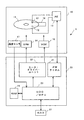
本形態のコモン電位決定処理の詳細を説明する前に、HDDの全体構成を説明する。図1は、HDDの全体構成を模式的に示すブロック図である。HDD1は、エンクロージャ10内に、データを記憶するディスクである磁気ディスク11を有している。スピンドル・モータ(SPM)は、磁気ディスク11を所定の角速度で回転する。磁気ディスク11の各記録面に対応して、磁気ディスク11にアクセスするヘッド・スライダ12が設けられている。アクセスは、リード及びライトの上位概念である。各ヘッド・スライダ12は、磁気ディスク上を飛行するスライダと、スライダに固定され磁気信号と電気信号との間の変換を行うヘッド素子部とを備えている。
Before describing the details of the common potential determination processing of this embodiment, the overall configuration of the HDD will be described. FIG. 1 is a block diagram schematically showing the overall configuration of the HDD. The HDD 1 has a
各ヘッド・スライダ12はアクチュエータ16の先端部に固定されている。本形態のヘッド・スライダ12は、さらに、熱によってヘッド素子部を膨張・突出させて浮上高を調整するヒータ素子を備えている。アクチュエータ16はボイス・コイル・モータ(VCM)15に連結され、回動軸を中心に回動することによって、ヘッド・スライダ12を回転する磁気ディスク11上においてその半径方向に移動する。アクチュエータ16とVCM15とは、ヘッド・スライダ12の移動機構である。
Each
エンクロージャ10の外側に固定された回路基板20上には、回路素子が実装されている。モータ・ドライバ・ユニット22は、HDC/MPU23からの制御データに従って、SPM14及びVCM15を駆動する。RAM24は、リード・データ及びライト・データを一時的に格納するバッファとして機能する。エンクロージャ10内のアーム電子回路(AE)13は、複数のヘッド・スライダ12の中から磁気ディスク11へのアクセスを行うヘッド・スライダ12を選択し、その再生信号を増幅してリード・ライト・チャネル(RWチャネル)21に送る。また、RWチャネル21からの記録信号を選択したヘッド・スライダ12に送る。AE13は、さらに、選択したヘッド・スライダ12のヒータ素子へ電力を供給し、その電力量を調節する調節回路として機能する。なお、本発明は一つのヘッド・スライダ12のみを有するHDDに適用することができる。
Circuit elements are mounted on the
RWチャネル21は、リード処理において、AE13から供給されたリード信号を一定の振幅となるように増幅し、取得したリード信号からデータを抽出し、デコード処理を行う。読み出されるデータは、ユーザ・データとサーボ・データとを含む。デコード処理されたリード・ユーザ・データ及びサーボ・データは、HDC/MPU23に供給される。また、RWチャネル21は、ライト処理において、HDC/MPU23から供給されたライト・データをコード変調し、更にコード変調されたライト・データをライト信号に変換してAE13に供給する。
In the read process, the
コントローラであるHDC/MPU23は、リード/ライト処理制御、コマンド実行順序の管理、サーボ信号を使用したヘッド・スライダ12のポジショニング制御(サーボ制御)、ホスト51との間のインターフェース制御、ディフェクト管理、エラーが発生した場合のエラー対応処理など、データ処理に関する必要な処理及びHDD1の全体制御を実行する。エンクロージャ内には温度センサ17が実装されており、HDC/MPU23は、この温度センサの検出温度に応じて、動作パラメータを設定する。本形態のHDC/MPU23は、特に、ヘッド・スライダ12に実装されている素子のコモン電位の調整処理を行う。以下、この処理について具体的に説明する。
The controller HDC /
HDC/MPU23は、ヘッド・スライダ12上の素子のコモン電位と浮上高との間の関係を測定により特定し、適切な動作コモン電位(素子の通常動作におけるコモン電位)を決定する。具体的には、HDC/MPU23はヘッド・スライダ12の浮上高を測定し、浮上高が最も高いと予想するコモン電位を、その素子の動作コモン電位として使用する。コモン電位は調整可能範囲内に限られているので、動作コモン電位は、その範囲内で最も浮上高が高いと予想する電位である。
The HDC /
浮上高の測定結果に基づいてコモン電位を調整することにより、ヘッド・スライダ12と磁気ディスク11との間の電位差を低減し、浮上高マージンを確保してヘッド・スライダ12と磁気ディスク11との接触の可能性を低減すると共に、接触においてヘッド・スライダ12と磁気ディスク11との間を流れる電流を低減し、磁気ディスク11のエロージョン/コロージョンを抑制する。
By adjusting the common potential based on the flying height measurement result, the potential difference between the
本形態のヘッド・スライダ12には、磁気抵抗効果素子であるリード素子、コイルで構成されたライト素子、さらに抵抗体で構成されたヒータ素子を有している。好ましくは、HDC/MPU23は、リード素子のコモン電位を調整することで、磁気ディスク11とヘッド・スライダ12との間の電位差を小さくする。
The
磁気ディスク11上にあるとき、リード素子には、サーボを読み出すために、略常にセンス電流が供給されている。このため、リード素子のコモン電位を調整することで、リードやライトなどの処理に拠らず、あるいは、シークやフォローイングなどの動作モードに拠らずに、磁気ディスク11とヘッド・スライダ12との間の電位差を小さい値に維持することができる。
When on the
一般に、リード素子はGMRあるいはTMRなどの磁気抵抗効果素子であり、磁気データを読み出すために、センス電流(バイアス電流)が供給される。コモン電位の調整によりセンス電流の値を変化させないために、磁気抵抗効果素子はディファレンシャルで駆動されていることが好ましい。ライト・コイルあるいはヒータ素子のコモン電位を調整する場合も、これらはディファレンシャルで動作する。以下において、磁気抵抗効果素子のリード素子においてコモン電位を調整する例について説明を行う。なお、本発明は、ライト素子やヒータ素子を有していないHDDに適用することができる。 Generally, the read element is a magnetoresistive effect element such as GMR or TMR, and a sense current (bias current) is supplied to read magnetic data. In order not to change the value of the sense current by adjusting the common potential, the magnetoresistive effect element is preferably driven differentially. Even when the common potential of the write coil or heater element is adjusted, these operate differentially. Hereinafter, an example in which the common potential is adjusted in the read element of the magnetoresistive effect element will be described. The present invention can be applied to an HDD that does not have a write element or a heater element.
まず、浮上高測定によるコモン電位の調整処理の全体の流れを説明する。図2のフローチャートに示すように、HDC/MPU23は、所定のタイミングにおいて、コモン電位の調整処理を開始する(S11)。HDC/MPU23は、複数の異なるコモン電位において浮上高を測定し(S12)、最適なコモン電位を決定する(S13)。HDC/MPU23は、上記最適なコモン電位を、リード素子の動作コモン電位としてセットする(S14)。リード素子は、磁気ディスク11からのデータ読み出しにおいて、上記決定されたコモン電位において動作する。
First, the overall flow of the common potential adjustment process based on the flying height measurement will be described. As shown in the flowchart of FIG. 2, the HDC /
HDC/MPU23は、AE13のレジスタに制御データをセットすることで、ヘッド・スライダ12上の素子の動作パラメータを設定することができる。動作パラメータは、ライト・コイル(ライト素子)のライト電流、磁気抵抗効果素子(リード素子)のセンス電流、磁気抵抗効果素子のコモン電位、ヒータ素子のヒータ・パワー値などである。また、HDC/MPU23は、AE13のレジスタに制御データをセットすることで、磁気ディスク11にアクセスする(浮上高測定を行う)ヘッド・スライダ12を選択する。
The HDC /
AE13は、HDC/MPU23がセットした制御データに従って、一つのヘッド・スライダ12を選択し、選択したヘッド・スライダ12に指定されたコモン電位を与える。図3は、AE13内のリード素子121のヘッド・バイアス回路130の構成を示す回路図である。ヘッド・バイアス回路130は、プラスとマイナスの電源ラインの間に接続されている。並列に接続されたトランジスタTr1〜Tr3、トランジスタTr3に直列接続されたトランジスタTr4、トランジスタTr4を制御するオペアンプOP1、トランジスタTr4に直列接続された抵抗R3、そしてオペアンプOP1の出力を制御する電流DAC131が定電流源回路を構成している。
The
電流DAC131の出力により、定電流源回路の出力電流、つまりリード素子121に流れるセンス電流が規定される。HDC/MPU23は、AE13に制御データをセットすることで、電流DACの出力値を制御することができる。一定のセンス電流における外部磁界の変化により、リード素子121の抵抗値が変化し、リード素子121の電圧が変化する。この電圧変化は、オペアンプOP3により、リード信号としてRWチャネル21に出力される。
More output
リード素子121と並列に接続され、それぞれが直列に接続された抵抗R1、R2、抵抗R1、R2に直列に接続されているトランジスタTr5、抵抗R1、R2の中間ノードに入力の一つが接続されトランジスタTr5を制御するオペアンプOP2、そしてオペアンプOP2を制御するオフセットDAC132は、コモン電位の調整回路を構成している。
One of the inputs is connected to the intermediate node of the resistors Tr1 and R2 connected in series with the read
典型的には、抵抗R1、R2の抵抗値は同一である。このとき、抵抗R1、R2の中間ノードの電位がコモン電位であり、リード素子121の中心電位である。オフセットDACの出力により、コモン電位が変化する。オフセットDAC132の出力は、HDC/MPU23がAE13にセットした制御データに従う。
Typically, the resistance values of the resistors R1 and R2 are the same. At this time, the potential of the intermediate node between the resistors R1 and R2 is the common potential and the center potential of the read
コモン電位の調整処理を開始する(S11)タイミングとし、起動時の初期設定処理において浮上高測定によるコモン電位調整を行うことが好ましい。磁気ディスク11の電位は環境により変化するため、リード素子121のコモン電位が一定であると、ヘッド・スライダ12と磁気ディスク11との間の電位差が環境により変化する。しかし、任意のタミングでこれを行うと、HDD1のパフォーマンスへの影響が懸念される。一方、起動後、HDD1の環境は一般には大きく変化することはない。そのため、起動毎にコモン電位を調整することで、環境による磁気ディスク11の電位変化に対応することができる。
It is preferable to perform the common potential adjustment by measuring the flying height in the initial setting process at the time of starting, with the timing of starting the adjustment process of the common potential (S11). Since the potential of the
起動後の環境変化が予想されるHDDにおいては、起動後の所定タイミングで、浮上高測定によるコモン電位調整を行ってもよい。好ましい例において、HDC/MPU23は、起動から予め設定された時間が経過した後に、パフォーマンスへの影響が小さいタイミング、例えば、ホスト51からのコマンド処理から開放されているアイドリング時に行う。これにより、起動後の環境変化や時間経過による磁気ディスク11の電位変動に応じて、より適切なコモン電位を設定することができる。
In an HDD in which an environmental change after startup is expected, common potential adjustment by flying height measurement may be performed at a predetermined timing after startup. In a preferred example, the HDC /
磁気ディスク11の電位に大きな影響を有する一つの要因は、温度である。図4は、温度と磁気ディスク11の電位との関係の例を示す測定データである。図4から理解されるように、温度の上昇により、磁気ディスク11の電位(V)が上昇する。HDC/MPU23は、浮上高測定によるコモン電位調整のタイミングの決定に、ディスク電位と温度との間の関係を利用することができる。
One factor having a great influence on the potential of the
例えば、毎起動時にコモン電位調整を行うのではなく、前回のコモン電位調整時の温度から閾値を越える温度変化があった場合に、HDC/MPU23はコモン電位調整を行うようにしてもよい。HDC/MPU23は、温度センサ17を参照してドライブ温度を知ることができる。HDC/MPU23は、コモン電位調整をしたときの検出温度を、磁気ディスク11やEEPROMなどの不揮発性メモリに保存しておき、起動時の初期化処理においてその値と現在の検出温度とを比較することができる。
For example, instead of performing the common potential adjustment at every start-up, the HDC /
同様に、起動後にコモン電位調整を行う場合も、前回のコモン電位調整時の温度からの閾値を越える温度変化を条件として、コモン電位調整を行うようにしてもよい。好ましい例において、HDC/MPU23は、前回のコモン電位調整からの経過時間に拠らず、前回コモン電位調整における温度から温度変化が閾値を越え、さらに、ホスト51からのコマンド処理から開放されているアイドリング時に、浮上高測定によるコモン電位調整を行う。
Similarly, when the common potential adjustment is performed after the start-up, the common potential adjustment may be performed on the condition that the temperature changes beyond the threshold value from the temperature at the previous common potential adjustment. In a preferred example, the HDC /
浮上高測定(S12)において、HDC/MPU23は、コモン電位を変化させて、異なるコモン電位において浮上高を測定する。浮上高の測定において、HDC/MPU23は絶対的な浮上高を測定してもよいが、測定した浮上高の相対的な違いを測定することができればよい。典型的には、AE13は、限られた可変範囲内でコモン電位を変化させることができる。また、HDC/MPU23が指定するコモン電位はデジタル値である。
In the flying height measurement (S12), the HDC /
一例において、AE13は、−500mV〜+500mVにおいてコモン電位を変化させる。また、HDC/MPU23は、上記範囲の中から選択した複数のコモン電位において、浮上高の測定を行う。例えば、HDC/MPU23は、100mV単位で浮上高測定に使用するコモン電位を選択する。好ましくは、HDC/MPU23は、動作コモン電位の可変範囲と同じ範囲内で浮上高の測定を行う。しかし、浮上高測定の範囲と動作コモン電位の可変範囲とが一致していなくともよい。
In one example, the
HDC/MPU23がヘッド・スライダ12の浮上高を測定するいくつかの方法がある。例えば、サーボ信号(リード信号の一つである)の読み出しにおいて、RWチャネル21内の可変ゲイン・アンプのゲイン(サーボ・ゲイン)は浮上高の増加により増加する。そのため、HDC/MPU23は、RWチャネル21からサーボ・ゲインを取得することで、ヘッド・スライダ12の浮上高変化を測定することができる。しかし、サーボ・ゲインは、浮上高を表すデータとしては、必ずしも正確なデータとはいえない。
There are several ways in which the HDC /
そこで、好ましい測定方法の一つは、磁気ディスク11に記録されているデータのリード信号のレゾリューション(周波数成分の分解能)により、浮上高を測定する。例えば、レゾリューションは、リード信号における特定の低周波信号と高周波信号の比で表すことができる。浮上高が小さくなると、リード信号の高周波成分の振幅が大きくなり、レゾリューションが大きくなる。HDC/MPU23は、異なるコモン電位においてレゾリューションを測定し、最も小さいレゾリューションのコモン電位、つまり、最も浮上高が高いコモン電位を特定する。
Therefore, one of the preferable measurement methods is to measure the flying height based on the resolution of the read signal of the data recorded on the magnetic disk 11 (resolution of the frequency component). For example, the resolution can be expressed by a ratio of a specific low frequency signal to a high frequency signal in the read signal. As the flying height decreases, the amplitude of the high-frequency component of the read signal increases and the resolution increases. The HDC /
HDC/MPU23は、演算処理によりレゾリューションを算出する、あるいは、RWチャネル21のパラメータからレゾリューションを特定することができる。例えば、RWチャネル21は、再生信号の周波数成分を補正するデジタルフィルタを有する。RWチャネル21は、リード信号の測定結果からこのフィルタのタップ値を補正する。この補正値はレゾリューションを表す。あるいは、RWチャネル21が、特定パターンの再生信号を基準パターンに復元するためのデジタルフィルタを有している場合、HDC/MPU23は、そのデジタルフィルタのタップの補正係数におけるレゾリューション成分の補正値を使用することができる。
The HDC /
他の好ましい浮上高測定方法は、ヘッド・スライダ12と磁気ディスク11とが接触するヒータ・パワー値を使用する。サーボ・ゲインやレゾリューションというリード信号から得られる値を使用するよりも、実際にヘッド・スライダ12と磁気ディスク11を接触させることで、より正確な浮上高測定を行うことができる。なお、ヘッド・スライダ12と磁気ディスク11との頻繁な接触が好ましくないHDDにおいては、上記のように接触を伴わない測定が好ましい。また、HDD1が、ヒータ素子と異なる浮上高調整機構を有している場合、その調整機構を使用することができる。
Another preferred flying height measurement method uses a heater power value at which the
HDC/MPU23は、特定のコモン電位が与えられている状態でヒータ・パワーを徐々に増加することにより、ヘッド・スライダ12と磁気ディスク11とが接触するヒータ・パワー値を特定することができる。HDC/MPU23は、リード信号の振幅変化やVCM15、SPM14の動作変化により、ヘッド・スライダ12と磁気ディスク11との接触を検出することができる。RWチャネル21が接触検出機能を有する場合は、HDC/MPU23はその機能を使用してもよい。
The HDC /
HDC/MPU23は、異なるコモン電位のそれぞれにおいて、磁気ディスク11とヘッド・スライダ12とが接触するヒータ・パワー値を測定する。HDC/MPU23は、最も浮上高が高い、つまり、接触ヒータ・パワー値が最も大きいコモン電位を特定する。このコモン電位は、測定において選択したコモン電位の内で、磁気ディスク11とヘッド・スライダ12との間の電位差を最も小さくするコモン電位である。
The HDC /
HDC/MPU23は、好ましくは、複数のゾーンにおいて、コモン電位決定のための浮上高測定を行う。広く知られているように、磁気ディスク11の記録面は、半径方向において複数のゾーンに分割されている。典型的には、ライト素子の記録周波数、リード素子のセンス電流、あるいはヒータ素子のヒータ・パワーは、ゾーン毎に設定される。
The HDC /
このため、コモン電位の設定もゾーン毎に行うことで、半径位置によらず磁気ディスク11とヘッド・スライダ12との間の電位差の低減を図ることができる。浮上高測定を全てのゾーンで行うことが好ましいが、処理時間短縮のため、一部の複数ゾーンにおいて異なるコモン電位での浮上高測定を行い、測定結果を他のゾーンに適用してもよい。例えば、内周側から奇数番目のゾーンにおいて測定を行い、その結果を測定を行ったゾーンとその隣の外周側ゾーンに適用することができる。
Therefore, by setting the common potential for each zone, the potential difference between the
HDC/MPU23は、コモン電位調整のための浮上高測定を、実装されている複数のヘッド・スライダ12の全てについて行ってもよい。しかし、最適なコモン電位を決定するための処理には浮上高測定が伴うため、相応の処理時間を要する。一方、磁気ディスク11の電位は、主にSPM14の構造、特に、流体軸受構造を有するSPM14においてはそのオイルの種類に依存する。そのため、各磁気ディスク11の電位は略同様である。
The HDC /
従って、好ましくは、HDC/MPU23は、複数のヘッド・スライダ12から選択した一つのヘッド・スライダ12について、浮上高測定により最適コモン電位を決定する。さらに、HDC/MPU23は、一つのヘッド・スライダ12において測定により決定した最適コモン電位を、他のヘッド・スライダ12にも適用する。これにより、全てのヘッド・スライダ12について適切なコモン電位を決定することができ、さらに、その処理時間の短縮を図ることができる。
Therefore, preferably, the HDC /
上述のように、HDC/MPU23は、離散的なコモン電位を指定して、浮上高の測定を行う。図5(a)〜(c)は、コモン電位と浮上高測定値との関係を模式的に示すグラフである。各図において、黒丸は測定値、点線はその近似線である。浮上高測定値とコモン電位との間の関係は、上記3つの態様をとりうる。つまり、浮上高は、コモン電位に対して、上に凸のグラフ、単調増加、あるいは単調減少を示す。実際の実装においては、一般に、図5(a)に示すように、測定範囲内で最高浮上高が現れるように、コモン電位の調整可能範囲を設定することができる。
As described above, the HDC /
典型的には、HDC/MPU23は、測定で指定したコモン電位(図5において、黒丸で示されている電位)から、リード素子の動作におけるコモン電位(動作コモン電位)を選択する(S13)。つまり、HDC/MPU23は、測定において最も高い浮上高を示したコモン電位を、実際に浮上高が最も高いコモン電位と予想し、その値をリード素子の動作で使用する。図5(a)においては左から4番目、図5(b)においては一番右、そして図5(c)においては一番左の測定値に対応するコモン電位である。
Typically, the HDC /
あるいは、HDC/MPU23は、測定の結果から、実際に浮上高を測定していないコモン電位を実際に浮上高が最も高いコモン電位と予想し、そのコモン電位を動作コモン電位として選択してもよい。例えば、HDC/MPU23は、最も高い浮上高を示した二つのコモン電位(図5(a)における左から4番目と5番目の測定値)の中間値を、実際に浮上高が最も高いコモン電位と予想することができる。
Alternatively, the HDC /
なお、本発明は、HDC/MPU23が、浮上高の測定に使用可能なコモン電位の範囲から外れた電位を、リード素子の動作電位の選択することを排除するものではない。測定範囲内において、浮上高が単調増加(図5(b))あるいは単調減少(図5(c))する場合には、測定範囲から外れたコモン電位を選択できることは有用である。
Note that the present invention does not exclude that the HDC /
HDC/MPU23は、コモン電位調整において、最も浮上高が高いと予想するコモン電位を決定する(S13)。従って、測定可能な全てのコモン電位において、浮上高を測定する必要はない。処理時間短縮のためにも、できるだけ少ない測定回数により最適なコモン電位を決定することができることが好ましい。
The HDC /
そこで、好ましくは、HDC/MPU23は、一部の測定可能コモン電位において浮上高測定を行い、最も浮上高が高いコモン電位を決定する。たとえば、図5の各グラフは、全ての測定値を示しているが、これらの内の一部のコモン電位において測定を行う。コモン電位の測定範囲における浮上高の変化は、図5に示すように、三つの態様が考えられる。一つは、コモン電位の測定範囲内に最も高い浮上高を示すコモン電位が存在し、その電位から上昇もしくは低下すると、浮上高は減少する(図5(a))。他の一つは、コモン電位の測定範囲内において、浮上高が単調増加する(図5(b))。そして、最後の一つにおいて、コモン電位の測定範囲内において、浮上高が単調減少する(図5(c))。
Therefore, preferably, the HDC /
浮上高が上記3つのいずれの変化を示すとしても、HDC/MPU23は、最初に、一つのコモン電位を選択し、そのコモン電位において浮上高の測定を開始する。このときの選択値である測定開始コモン電位は、測定範囲の最大値及び最小値以外の値を選択する。好ましくは、HDC/MPU23は、前回測定において決定した最適コモン電位、あるいは、浮上高測定に使用するコモン電位の内で前回の最適コモン電位に最も近い電位を選択する。この値は、磁気ディスク11やEEPROMなどの不揮発性メモリに保存しておく。
Even if the flying height shows any of the above three changes, the HDC /
好ましい他の例において、HDC/MPU23は、前回の最適コモン電位と、前回測定にけるドライブ温度(温度センサ17の検出温度)及び今回測定におけるドライブ温度とから、上記の最初の測定に使用するコモン電位を決定する。図4を参照して説明したように、磁気ディスク11の電位は温度により変化する。
In another preferable example, the HDC /
そのため、HDC/MPU23は、前回測定からの温度変化による磁気ディスク11の電位変化を予想し、その磁気ディスク11の電位変化から現在の最適なコモン電位をある程度予想する。このコモン電位から測定を開始することで、処理時間の短縮を図ることができる。あるいは、HDC/MPU23は、予めドライブ温度と測定開始コモン電位との関係を特定したデータを有し、そのデータとドライブ温度とに従って最初のコモン電位を選択してもよい。
Therefore, the HDC /
次に、HDC/MPU23は、最初のコモン電位よりも一つ上もしくは下のコモン電位を選択して、浮上高の測定を行う。このとき、前回測定におけるドライブ温度と今回測定におけるドライブ温度の関係から、いずれのコモン電位を選択するか決定してもよい。例えば、最初の選択コモン電位が前回の最適コモン電位である場合、温度が低下しているときは低いコモン電位、上昇しているときは高いコモン電位を選択する。上述のように、HDC/MPU23は、所定の測定範囲において、離散値のコモン電位を設定する。HDC/MPU23は、最初のコモン電位と次のコモン電位における浮上高を比較して、二つの測定点が含まれる部分の傾きを決定する。
Next, the HDC /
傾きが正であれば、測定した二つのコモン電位よりも大きなコモン電位において、次の測定を行う。典型的には、測定したコモン電位の内の大きい電位の一つ上のコモン電位を選択する。傾きが負であれば、二つのコモン電位よりも小さいコモン電位において次の測定を行う。同様に、典型的には、測定したコモン電位の内の小さい電位の一つ下のコモン電位を選択する。 If the slope is positive, the next measurement is performed at a common potential larger than the two measured common potentials. Typically, a common potential that is one higher than the measured common potential is selected. If the slope is negative, the next measurement is performed at a common potential smaller than the two common potentials. Similarly, typically, a common potential that is one lower of the measured common potentials is selected.
このようにコモン電位を順次選択し、各コモン電位において浮上高測定を行う。浮上高測定を繰り返し、浮上高の傾きに変化があれば、その一つ前の測定におけるコモン電位において、浮上高が最も高い。傾きに変化がない場合は、最後の測定におけるコモン電位が測定範囲内で最も浮上高が高いコモン電位である。 Thus, the common potential is sequentially selected, and the flying height is measured at each common potential. If the flying height measurement is repeated and there is a change in the flying height slope, the flying height is the highest at the common potential in the previous measurement. When there is no change in the slope, the common potential in the last measurement is the common potential with the highest flying height within the measurement range.
以上、本発明を好ましい実施形態を例として説明したが、本発明が上記の実施形態に限定されるものではない。当業者であれば、上記の実施形態の各要素を、本発明の範囲において容易に変更、追加、変換することが可能である。本発明は、ピエゾ素子などのTFC以外の浮上高調整機構を有するディスク・ドライブに適用することができる。本発明は、HDD以外のディスク・ドライブに適用してもよい。本発明において、最適なコモン電位としては、最高浮上高と予想するコモン電位を選択することが好ましいが、設計における電位差以外の要因を考慮して、これと異なるコモン電位を選択することを排除するものではない。 As mentioned above, although this invention was demonstrated taking preferable embodiment as an example, this invention is not limited to said embodiment. A person skilled in the art can easily change, add, and convert each element of the above-described embodiment within the scope of the present invention. The present invention can be applied to a disk drive having a flying height adjustment mechanism other than TFC such as a piezo element. The present invention may be applied to disk drives other than HDDs. In the present invention, it is preferable to select a common potential that is expected to have the highest flying height as the optimum common potential, but it is excluded to select a different common potential in consideration of factors other than the potential difference in the design. It is not a thing.
1 ハードディスク・ドライブ、10 エンクロージャ、11 磁気ディスク
12 ヘッド・スライダ、13 アーム・エレクトロニクス
14 スピンドル・モータ、15 ボイス・コイル・モータ
16 アクチュエータ、20 回路基板、21 リード・ライト・チャネル
22 モータ・ドライバ・ユニット、23 ハードディスク・コントローラ/MPU
24 RAM、130 ドライバ回路、131 電流DAC
132 オフセットDAC
DESCRIPTION OF SYMBOLS 1 Hard disk drive, 10 Enclosure, 11
24 RAM , 1 30 Driver circuit, 131 Current DAC
132 Offset DAC
Claims (14)
前記ディスクを回転するモータと、
回転している前記ディスクの記録面上を浮上するスライダと、そのスライダ上の素子と、を有するヘッド・スライダと、
起動時又は起動後に、前記素子の異なるコモン電位において前記ヘッド・スライダと前記ディスクとの間の浮上高を測定し、その測定結果から動作コモン電位を決定するコントローラと、
を有し、
前記コントローラは、前回の測定における温度からの温度変化に基づいて、前記測定を行うタイミングを決定し、前記測定の結果から前記浮上高が最も高いと予想されるコモン電位を決定し、その決定したコモン電位において前記素子を使用する、
ディスク・ドライブ。 A disk for storing data;
A motor for rotating the disk;
A head slider having a slider flying above the recording surface of the rotating disk and an element on the slider;
A controller that measures the flying height between the head slider and the disk at a different common potential of the element at the time of startup or after startup, and determines an operating common potential from the measurement result;
Have
The controller determines the timing for performing the measurement based on the temperature change from the temperature in the previous measurement, determines the common potential expected to have the highest flying height from the measurement result, and determines Using the element at a common potential,
Disk drive.
請求項1に記載のディスク・ドライブ。 The disk is a magnetic disk, and the element is a magnetoresistive effect element that is a read element.
The disk drive of claim 1.
請求項1に記載のディスク・ドライブ。 The disk is a magnetic disk, and the element is a write element or a heater element.
The disk drive of claim 1.
前記コントローラは、異なるコモン電位において前記機構により前記浮上高を変化させることにより前記ヘッド・スライダを前記ディスクに接触させて、前記浮上高を測定する、
請求項1に記載のディスク・ドライブ。 The disk drive further includes a mechanism for adjusting a flying height between the head slider and the disk,
The controller measures the flying height by bringing the head slider into contact with the disk by changing the flying height by the mechanism at different common potentials.
The disk drive of claim 1.
請求項1に記載のディスク・ドライブ。 The controller measures the flying height using a read signal read by a read element;
The disk drive of claim 1.
前記コントローラは、一つのヘッド・スライダについての測定結果を全てのヘッド・スライダに適用する、
請求項1に記載のディスク・ドライブ。 Having multiple head sliders,
The controller applies the measurement result for one head slider to all the head sliders.
The disk drive of claim 1.
前記コントローラは、異なるゾーンにおいて前記測定を行い、その異なるゾーンのそれぞれにおけるコモン電位を決定する、
請求項1に記載のディスク・ドライブ。 The recording surface is divided into a plurality of zones, and a recording frequency is determined for each zone,
The controller performs the measurement in different zones and determines a common potential in each of the different zones;
The disk drive of claim 1.
請求項1に記載のディスク・ドライブ。 The controller starts measurement of the flying height at the measurement start common potential, performs measurement at at least one common potential on the upper and lower sides of the measurement start common potential, and the flying height becomes higher than the measurement start common potential. Continue measuring the flying height at the common potential on the side,
The disk drive of claim 1.
ディスクを回転し、
起動時又は起動後に、前記回転しているディスクの記録面上を飛行しているヘッド・スライダの浮上高を、そのヘッド・スライダ上の素子の異なるコモン電位において測定し、
前記測定の結果から、前記素子の動作コモン電位を決定し、
前記動作コモン電位において前記素子を動作させる方法であり、
前回の測定における温度からの温度変化に基づいて、前記測定を行うタイミングを決定し、前記測定の結果から前記浮上高が最も高いと予想されるコモン電位を決定し、その決定したコモン電位において前記素子を使用する、
方法。 A method of adjusting a common potential of an element on a head slider in a disk drive,
Rotate the disc
Measuring the flying height of the head slider flying over the recording surface of the rotating disk at or after startup, at different common potentials of the elements on the head slider;
From the result of the measurement, determine the operating common potential of the element,
A method of operating the element at the operating common potential;
Based on the temperature change from the temperature in the previous measurement, determine the timing to perform the measurement, determine the common potential that is expected to have the highest flying height from the result of the measurement, in the determined common potential Use elements,
Method.
請求項9に記載の方法。 Measuring the flying height by bringing the head slider into contact with the disk by changing the flying height by a mechanism for adjusting the flying height between the head slider and the disk at different common potentials;
The method of claim 9.
請求項9に記載の方法。 Measuring the flying height using a read signal read by a read element;
The method of claim 9.
一つのヘッド・スライダについての測定結果を全てのヘッド・スライダに適用する、
請求項9に記載の方法。 The disk drive has a plurality of head sliders and a recording surface corresponding to each of the plurality of head sliders,
Apply the measurement results for one head slider to all head sliders.
The method of claim 9.
異なるゾーンにおいて前記測定を行い、その異なるゾーンのそれぞれにおけるコモン電位を決定する、
請求項9に記載の方法。 The recording surface is divided into a plurality of zones, and a recording frequency is determined for each zone,
Making the measurements in different zones and determining the common potential in each of the different zones;
The method of claim 9.
請求項9に記載の方法。 The measurement of the flying height is started at the measurement start common potential, the measurement is performed at at least one common potential above and below the measurement start common potential, and the common potential on the side where the flying height is higher than the measurement start common potential To continue measuring the flying height at
The method of claim 9.
Priority Applications (2)
| Application Number | Priority Date | Filing Date | Title |
|---|---|---|---|
| JP2008241856A JP5080411B2 (en) | 2008-09-19 | 2008-09-19 | Method for adjusting common potential of elements on disk drive and head slider |
| US12/562,589 US8125727B2 (en) | 2008-09-19 | 2009-09-18 | Disk drive and method for adjusting common-mode voltage of an element on a head-slider |
Applications Claiming Priority (1)
| Application Number | Priority Date | Filing Date | Title |
|---|---|---|---|
| JP2008241856A JP5080411B2 (en) | 2008-09-19 | 2008-09-19 | Method for adjusting common potential of elements on disk drive and head slider |
Publications (3)
| Publication Number | Publication Date |
|---|---|
| JP2010073283A JP2010073283A (en) | 2010-04-02 |
| JP2010073283A5 JP2010073283A5 (en) | 2011-09-22 |
| JP5080411B2 true JP5080411B2 (en) | 2012-11-21 |
Family
ID=42204911
Family Applications (1)
| Application Number | Title | Priority Date | Filing Date |
|---|---|---|---|
| JP2008241856A Expired - Fee Related JP5080411B2 (en) | 2008-09-19 | 2008-09-19 | Method for adjusting common potential of elements on disk drive and head slider |
Country Status (2)
| Country | Link |
|---|---|
| US (1) | US8125727B2 (en) |
| JP (1) | JP5080411B2 (en) |
Families Citing this family (9)
| Publication number | Priority date | Publication date | Assignee | Title |
|---|---|---|---|---|
| US8681442B2 (en) * | 2012-05-11 | 2014-03-25 | Western Digital Technologies, Inc. | Disk drive comprising extended range head proximity sensor |
| US20140240871A1 (en) * | 2013-02-28 | 2014-08-28 | HGST Netherlands B.V. | Interface voltage control operating point determination in a hard disk drive |
| US10244618B2 (en) | 2015-10-29 | 2019-03-26 | Western Digital Technologies, Inc. | Patterned ground structure filter designs with improved performance |
| US10411670B2 (en) | 2017-06-27 | 2019-09-10 | Western Digital Technologies, Inc. | Compact broadband common-mode filter |
| US10650850B1 (en) | 2019-02-07 | 2020-05-12 | Western Digital Technologies, Inc. | Hard disk drive with write gap conductive structure and dual independent interface voltage control circuitry |
| CN110323978B (en) * | 2019-06-27 | 2021-01-05 | 中车青岛四方机车车辆股份有限公司 | Linear generator control method and device |
| US10910007B1 (en) | 2020-02-14 | 2021-02-02 | Western Digital Technologies, Inc. | Heat-assisted magnetic recording device capable of providing negative electrical potential at NFT |
| US11160162B1 (en) | 2020-06-29 | 2021-10-26 | Western Digital Technologies, Inc. | Via-less patterned ground structure common-mode filter |
| US11659650B2 (en) | 2020-12-18 | 2023-05-23 | Western Digital Technologies, Inc. | Dual-spiral common-mode filter |
Family Cites Families (14)
| Publication number | Priority date | Publication date | Assignee | Title |
|---|---|---|---|---|
| JPS5278415A (en) * | 1975-12-25 | 1977-07-01 | Nec Corp | Floating head device |
| JPH0224882A (en) * | 1988-07-13 | 1990-01-26 | Nec Corp | Magnetic dick device |
| US4879610A (en) * | 1988-09-28 | 1989-11-07 | International Business Machines Corporation | Protective circuit for a magnetoresistive element |
| DE69531931T2 (en) * | 1994-12-30 | 2004-07-29 | STMicroelectronics, Inc., Carrollton | Symmetrical ohmic current transformer circuit and method therefor |
| JP3550024B2 (en) * | 1998-06-18 | 2004-08-04 | 富士通株式会社 | Information storage device and servo gain correction method for information storage device |
| US6822816B2 (en) * | 2002-05-23 | 2004-11-23 | Seagate Technology Llc | Electrical detection of low flying read/write head for a disc drive |
| KR100640621B1 (en) * | 2004-12-28 | 2006-11-01 | 삼성전자주식회사 | Apparatus and method for adjusting a flying height of magnetic head in disk drive |
| JP2007042239A (en) * | 2005-08-04 | 2007-02-15 | Hitachi Global Storage Technologies Netherlands Bv | Magnetic disk device and manufacturing method of magnetic disk device |
| JP2007213653A (en) * | 2006-02-07 | 2007-08-23 | Fujitsu Ltd | Interval controller |
| JP2007250102A (en) * | 2006-03-16 | 2007-09-27 | Fujitsu Ltd | Storage device |
| JP2007334931A (en) * | 2006-06-12 | 2007-12-27 | Teac Corp | Optical disk device |
| US7656600B2 (en) * | 2006-08-25 | 2010-02-02 | Seagate Technology Llc | Monitoring transducer potential to detect an operating condition |
| JP4850722B2 (en) * | 2007-01-05 | 2012-01-11 | ヒタチグローバルストレージテクノロジーズネザーランドビーブイ | Magnetic disk device, preamplifier for magnetic disk device, flexible printed cable assembly for magnetic disk device |
| JP2008171520A (en) * | 2007-01-15 | 2008-07-24 | Fujitsu Ltd | Controller, control method, and storage device |
-
2008
- 2008-09-19 JP JP2008241856A patent/JP5080411B2/en not_active Expired - Fee Related
-
2009
- 2009-09-18 US US12/562,589 patent/US8125727B2/en not_active Expired - Fee Related
Also Published As
| Publication number | Publication date |
|---|---|
| US8125727B2 (en) | 2012-02-28 |
| US20110090586A1 (en) | 2011-04-21 |
| JP2010073283A (en) | 2010-04-02 |
Similar Documents
| Publication | Publication Date | Title |
|---|---|---|
| JP5080411B2 (en) | Method for adjusting common potential of elements on disk drive and head slider | |
| JP4728929B2 (en) | Control device, control method, and storage device | |
| JP4909878B2 (en) | Disk drive device and clearance adjustment method thereof | |
| JP2006252593A (en) | Magnetic disk device, control method and manufacturing method thereof | |
| US20060176004A1 (en) | Data storage apparatus with compensation for vibration and control method thereof | |
| JP2009157987A (en) | Method for adjusting recess depth of head slider and disk drive device | |
| JP2007310957A (en) | Controller for storage/reproduction mechanism | |
| JP2008123651A (en) | Disk drive device and calibration method thereof | |
| US7265931B2 (en) | Apparatus to reject disk drive disturbance | |
| JP2008234745A (en) | Method for determining control value for controlling clearance adjustment value between head and disk, disk drive apparatus, and manufacturing method thereof | |
| US7342736B1 (en) | Methods and disk drive that measure head flying height at power-on/off | |
| JP2007294007A (en) | Disk drive device and control method thereof | |
| JP2007287290A (en) | Disk drive and its calibration method | |
| JP2011018396A (en) | Disk drive and clearance measuring method | |
| KR100712559B1 (en) | Method and apparatus for adjusting frequency of reference clock and disc drive using the same | |
| JP2008293625A (en) | Apparatus and method for determining control value to control clearance between head and disk, and magnetic disk drive device | |
| JP2007250162A (en) | Media drive device and its control method | |
| JP3611752B2 (en) | System and method for measuring relative and absolute amplitudes of signals read from a data storage medium | |
| US7982991B2 (en) | Method and apparatus for determining set value of write current of magnetic head | |
| JP5052035B2 (en) | Control method of recording intensity of hard disk drive, recording medium, and hard disk drive | |
| JP2010067323A (en) | Disk drive and method for measuring clearance change | |
| JP4986876B2 (en) | Disk drive device | |
| US7088546B2 (en) | Method to reject disk drive disturbance | |
| JP2005209281A (en) | Data storage device, control method for storage device and magnetic disk driving device | |
| JP2009151890A (en) | Magnetic disk device and contact detecting method of magnetic head slider |
Legal Events
| Date | Code | Title | Description |
|---|---|---|---|
| RD04 | Notification of resignation of power of attorney |
Free format text: JAPANESE INTERMEDIATE CODE: A7424 Effective date: 20100510 |
|
| A521 | Written amendment |
Free format text: JAPANESE INTERMEDIATE CODE: A523 Effective date: 20110804 |
|
| A621 | Written request for application examination |
Free format text: JAPANESE INTERMEDIATE CODE: A621 Effective date: 20110804 |
|
| A977 | Report on retrieval |
Free format text: JAPANESE INTERMEDIATE CODE: A971007 Effective date: 20120130 |
|
| A131 | Notification of reasons for refusal |
Free format text: JAPANESE INTERMEDIATE CODE: A131 Effective date: 20120207 |
|
| A521 | Written amendment |
Free format text: JAPANESE INTERMEDIATE CODE: A523 Effective date: 20120326 |
|
| A131 | Notification of reasons for refusal |
Free format text: JAPANESE INTERMEDIATE CODE: A131 Effective date: 20120508 |
|
| A521 | Written amendment |
Free format text: JAPANESE INTERMEDIATE CODE: A523 Effective date: 20120730 |
|
| TRDD | Decision of grant or rejection written | ||
| A01 | Written decision to grant a patent or to grant a registration (utility model) |
Free format text: JAPANESE INTERMEDIATE CODE: A01 Effective date: 20120821 |
|
| A01 | Written decision to grant a patent or to grant a registration (utility model) |
Free format text: JAPANESE INTERMEDIATE CODE: A01 |
|
| A61 | First payment of annual fees (during grant procedure) |
Free format text: JAPANESE INTERMEDIATE CODE: A61 Effective date: 20120830 |
|
| FPAY | Renewal fee payment (event date is renewal date of database) |
Free format text: PAYMENT UNTIL: 20150907 Year of fee payment: 3 |
|
| R150 | Certificate of patent or registration of utility model |
Free format text: JAPANESE INTERMEDIATE CODE: R150 |
|
| R250 | Receipt of annual fees |
Free format text: JAPANESE INTERMEDIATE CODE: R250 |
|
| R250 | Receipt of annual fees |
Free format text: JAPANESE INTERMEDIATE CODE: R250 |
|
| LAPS | Cancellation because of no payment of annual fees |