JP5067874B2 - Sheet conveying apparatus and image forming apparatus - Google Patents
Sheet conveying apparatus and image forming apparatus Download PDFInfo
- Publication number
- JP5067874B2 JP5067874B2 JP2008085291A JP2008085291A JP5067874B2 JP 5067874 B2 JP5067874 B2 JP 5067874B2 JP 2008085291 A JP2008085291 A JP 2008085291A JP 2008085291 A JP2008085291 A JP 2008085291A JP 5067874 B2 JP5067874 B2 JP 5067874B2
- Authority
- JP
- Japan
- Prior art keywords
- sheet
- conveying
- rotating body
- roller pair
- conveyance
- Prior art date
- Legal status (The legal status is an assumption and is not a legal conclusion. Google has not performed a legal analysis and makes no representation as to the accuracy of the status listed.)
- Active
Links
Images


Classifications
-
- B—PERFORMING OPERATIONS; TRANSPORTING
- B65—CONVEYING; PACKING; STORING; HANDLING THIN OR FILAMENTARY MATERIAL
- B65H—HANDLING THIN OR FILAMENTARY MATERIAL, e.g. SHEETS, WEBS, CABLES
- B65H5/00—Feeding articles separated from piles; Feeding articles to machines
- B65H5/06—Feeding articles separated from piles; Feeding articles to machines by rollers or balls, e.g. between rollers
- B65H5/062—Feeding articles separated from piles; Feeding articles to machines by rollers or balls, e.g. between rollers between rollers or balls
-
- B—PERFORMING OPERATIONS; TRANSPORTING
- B65—CONVEYING; PACKING; STORING; HANDLING THIN OR FILAMENTARY MATERIAL
- B65H—HANDLING THIN OR FILAMENTARY MATERIAL, e.g. SHEETS, WEBS, CABLES
- B65H9/00—Registering, e.g. orientating, articles; Devices therefor
- B65H9/004—Deskewing sheet by abutting against a stop, i.e. producing a buckling of the sheet
- B65H9/006—Deskewing sheet by abutting against a stop, i.e. producing a buckling of the sheet the stop being formed by forwarding means in stand-by
-
- B—PERFORMING OPERATIONS; TRANSPORTING
- B65—CONVEYING; PACKING; STORING; HANDLING THIN OR FILAMENTARY MATERIAL
- B65H—HANDLING THIN OR FILAMENTARY MATERIAL, e.g. SHEETS, WEBS, CABLES
- B65H2220/00—Function indicators
- B65H2220/09—Function indicators indicating that several of an entity are present
-
- B—PERFORMING OPERATIONS; TRANSPORTING
- B65—CONVEYING; PACKING; STORING; HANDLING THIN OR FILAMENTARY MATERIAL
- B65H—HANDLING THIN OR FILAMENTARY MATERIAL, e.g. SHEETS, WEBS, CABLES
- B65H2404/00—Parts for transporting or guiding the handled material
- B65H2404/10—Rollers
- B65H2404/14—Roller pairs
-
- B—PERFORMING OPERATIONS; TRANSPORTING
- B65—CONVEYING; PACKING; STORING; HANDLING THIN OR FILAMENTARY MATERIAL
- B65H—HANDLING THIN OR FILAMENTARY MATERIAL, e.g. SHEETS, WEBS, CABLES
- B65H2513/00—Dynamic entities; Timing aspects
- B65H2513/10—Speed
-
- B—PERFORMING OPERATIONS; TRANSPORTING
- B65—CONVEYING; PACKING; STORING; HANDLING THIN OR FILAMENTARY MATERIAL
- B65H—HANDLING THIN OR FILAMENTARY MATERIAL, e.g. SHEETS, WEBS, CABLES
- B65H2801/00—Application field
- B65H2801/03—Image reproduction devices
- B65H2801/06—Office-type machines, e.g. photocopiers
Description
本発明は、シート搬送装置及び画像形成装置に関し、特にシートを搬送するシート搬送回転体のシート搬送速度の設定に関する。 The present invention relates to a sheet conveying apparatus and an image forming apparatus, and more particularly to setting a sheet conveying speed of a sheet conveying rotating body that conveys a sheet.
従来、プリンタ、複写機、FAX等の画像形成装置においては、画像形成部に記録紙等のシートを搬送するシート搬送装置を備えている。そして、画像形成の際には、シート搬送装置により、まずシートを像担持体上に形成されたトナー像を転写する転写部に搬送した後、定着部に搬送することにより、トナー像をシート上に定着させようにしている。 2. Description of the Related Art Conventionally, image forming apparatuses such as printers, copiers, and fax machines are provided with a sheet conveying device that conveys a sheet such as recording paper to an image forming unit. When forming an image, the sheet conveying device first conveys the toner image formed on the image carrier to a transfer unit that transfers the toner image, and then conveys the toner image to the fixing unit. To try to fix.
また、画像形成装置としては、シートの両面に画像を形成するものがあり、このような画像形成装置においては、反転部を設けるようにしている。そして、シートの両面に画像を形成する場合は、第1面に画像が形成されたシートを反転部により反転させた後、シートをシート搬送装置により転写部に搬送するようにしている。 Some image forming apparatuses form images on both sides of a sheet. In such an image forming apparatus, a reversing unit is provided. When images are formed on both surfaces of the sheet, the sheet on which the image is formed on the first surface is reversed by the reversing unit, and then the sheet is conveyed to the transfer unit by the sheet conveying device.
ところで、このような従来の画像形成装置に設けられたシート搬送装置においては、給紙カセットからシートを転写部に搬送するため、ゴム素材等を使用した複数のシート搬送回転体であるローラを用いている。ここで、適切なシートの搬送のためには、ローラのシート搬送速度は、常に一定である必要がある。 By the way, in the sheet conveying apparatus provided in such a conventional image forming apparatus, in order to convey the sheet from the sheet feeding cassette to the transfer unit, a plurality of rollers that are sheet conveying rotating bodies using a rubber material or the like are used. ing. Here, for proper sheet conveyance, the sheet conveyance speed of the roller needs to be always constant.
しかし、実際には、ローラの外径公差、通紙枚数や置かれている環境によって、摩擦係数等のローラ表面状態が変化するため、複数のローラのシート搬送速度を常に一定に保つことは不可能である。そして、特に転写部に一番近いローラにおいてシート搬送速度が変化した場合、色ズレが発生し、画像劣化を招く恐れがある。 However, in reality, the roller surface condition such as the coefficient of friction changes depending on the tolerance of the outer diameter of the roller, the number of sheets to be passed, and the environment in which the roller is placed. Is possible. In particular, when the sheet conveyance speed changes in the roller closest to the transfer unit, color misregistration may occur and image deterioration may occur.
このため、従来は転写部に一番近いローラのシート搬送速度を安定させるため、各ローラのシート搬送速度に差を持たせることにより、転写部に一番近いローラのシート搬送速度を安定させるようにしたものがある(特許文献1及び特許文献2参照)。
Therefore, conventionally, in order to stabilize the sheet conveyance speed of the roller closest to the transfer unit, the sheet conveyance speed of the roller closest to the transfer unit is stabilized by providing a difference in the sheet conveyance speed of each roller. (See
図7は、このような従来のシート搬送装置の構成を示す図である。 FIG. 7 is a diagram showing the configuration of such a conventional sheet conveying apparatus.
給紙カセット100から給送ローラ101によって一枚ずつシートSが搬送されると、このシートSは、中間搬送ローラ対102、レジストローラ対103により順次搬送され、吸着ローラ104によって搬送ベルト105に吸着後、転写部106に搬送される。
When the sheet S is conveyed one by one from the
ここで、図7において、V1は吸着ローラ104及び搬送ベルト105のシート搬送速度、V2はレジストローラ対103のシート搬送速度、V3は中間搬送ローラ対102のシート搬送速度を示している。そして、これらの各シート搬送速度は、V1>V3>V2となるように設定されている。107は、中間搬送ローラ対102とレジストローラ対103との間に設けられた搬送ガイドである。
Here, in FIG. 7, V1 indicates the sheet conveyance speed of the
このようにシート搬送速度が設定された場合、シートSが中間搬送ローラ対102にニップされると、シートSは中間搬送ローラ対102によりシート搬送速度V3で搬送される。次に、シートSがレジストローラ対103に達すると、シートSはレジストローラ対103よりシート搬送速度V2で搬送されるようになる。
When the sheet conveyance speed is set in this way, when the sheet S is nipped by the intermediate
ここで、このようにシートSがレジストローラ対103に達したとき、シートSの一部は、まだ中間搬送ローラ対102によりシート搬送速度V3で搬送されている。このため、V3>V2の関係により中間搬送ローラ対102とレジストローラ対103の間でシートSが撓み、ループが発生する。つまり、シートSがレジストローラ対103に達すると、シートSは、ループを形成しながらレジストローラ対103により、シート搬送速度V2で搬送される。
Here, when the sheet S reaches the
次に、レジストローラ対103よりシート搬送速度V2で搬送されたシートSが、吸着ローラ104を介して搬送ベルト105に達すると、シートSはシート搬送速度V1で吸着ローラ104及び搬送ベルト105により転写部106に搬送される。ここで、このようにシートSが搬送ベルト105に達したとき、シートSの一部は、まだレジストローラ対103によりシート搬送速度V2で搬送されている。このため、V1>V2の関係により、シートSは吸着ローラ104とレジストローラ対103間で引っ張られる状態になる。
Next, when the sheet S conveyed from the
なお、このようにシートSが引っ張られると、レジストローラ対103の駆動部にはワンウェイクラッチ機構が組み込まれているため、レジストローラ対103はシートSと一体に回転するようになる。つまり、シートSが搬送ベルト105により搬送されるようになると、レジストローラ対103のシート搬送速度はV1となる。
When the sheet S is pulled in this manner, the
一方、レジストローラ対103のシート搬送速度がV1となると、V1>V3の関係から、中間搬送ローラ対102とレジストローラ対103との間にV3>V2の関係で発生したループは徐々に減少していく。そして、ループがなくなると、シートSは引張り状態になってしまう恐れがある。
On the other hand, when the sheet conveyance speed of the
なお、このようにシートSが引張り状態となった場合でも、中間搬送ローラ対102の駆動部にもワンウェイクラッチ機構が組み込まれているため、中間搬送ローラ対102はシートSと一体に回転するようになる。そして、このようにシートSと一体に回転すると、中間搬送ローラ対102のシート搬送速度はV1となる。
Even when the sheet S is pulled in this manner, the one-way clutch mechanism is also incorporated in the drive unit of the intermediate
このように、シートSが搬送ベルト105により搬送されるようになると、中間搬送ローラ対102及びレジストローラ対103のシート搬送速度はV1となる。これにより、全体のシート搬送速度は一定のV1となり、転写部106へ安定したシート搬送速度V1で搬送することができる。
Thus, when the sheet S is conveyed by the
ところで、近年、画像形成装置の小型化が図られており、このため従来の画像形成装置においては、シート搬送経路を湾曲させるようにしている。しかし、このようにシート搬送経路を湾曲させた場合、従来のシート搬送装置において、転写部へシートを安定して搬送するよう既述したようにシートを引っ張るようにすると、引っ張られたシートがシート搬送経路を構成する搬送ガイドと接触する場合がある。 Incidentally, in recent years, the image forming apparatus has been downsized. For this reason, in the conventional image forming apparatus, the sheet conveyance path is curved. However, when the sheet conveyance path is curved in this way, in the conventional sheet conveyance apparatus, if the sheet is pulled as described above so as to stably convey the sheet to the transfer unit, the pulled sheet becomes a sheet. There is a case where it comes into contact with a conveyance guide constituting the conveyance path.
そして、このようにシートが搬送ガイドと接触すると、シートの摺動抵抗が大きくなってシート転写直前の搬送ローラに負荷がかかるようになる。この結果、多数のシートを搬送すると、シート転写直前の搬送ローラは摩耗し、転写部へ継続的に安定した搬送速度でシートを搬送することができない。 When the sheet comes into contact with the conveyance guide in this way, the sliding resistance of the sheet increases, and a load is applied to the conveyance roller immediately before the sheet transfer. As a result, when a large number of sheets are conveyed, the conveyance roller immediately before the sheet transfer is worn, and the sheet cannot be conveyed continuously and stably at the conveyance speed.
また、給紙カセット100から給送ローラ101によって送り出されたシートを1枚ずつ分離する分離部として、バックテンションが大きくなる構成のものを用いる場合がある。この場合、シート転写直前の搬送ローラのシート搬送速度が一番速くなるように設定すると、転写直前の搬送ローラで搬送するときに分離部からシートを引っ張る力が加わるようになる。このため、大きな搬送力が転写直前の搬送ローラに必要となり、スリップの発生やローラの摩耗を助長してしまう。
In some cases, a separation unit that increases back tension is used as a separation unit that separates the sheets fed from the
そして、このように転写部へ継続的に安定した搬送速度でシートを搬送できない場合、またスリップやローラの摩耗が発生すると、転写部における色ズレが発生し、シートに対する安定した画像形成ができないという問題点があった。 If the sheet cannot be transported to the transfer unit at a continuously stable speed, or if slippage or roller wear occurs, color shift occurs in the transfer unit, and stable image formation on the sheet cannot be performed. There was a problem.
また、特許文献2のものには、V1<V3とした場合には、中間搬送ローラ対102とレジストローラ対103の速度差によりレジストローラ対103の上流側に在るループがどんどん大きくなる。その結果、レジストローラ対103の上流に在るループがある大きさを超えると、今度はそのループがレジストローラ対103からシートを押し出すこととなり、最後には転写部にシートを押し出すこととなり、不具合が発生するとの記載がある。
Further, according to Patent Document 2, when V1 <V3, the loop on the upstream side of the
ここで、既述したように分離部によるバックテンションを確実に受けないようにするためには、転写前のローラの上流側においてシートにループを形成するように構成することが好ましい。一方で、特許文献2に記載のようにシートにループが形成されるとシートのこしによって転写前のローラに対してシートが押し込まれることで、シート搬送に不具合が生じる恐れがある。 Here, as described above, in order to ensure that the back tension by the separating portion is not received, it is preferable to form a loop on the sheet on the upstream side of the roller before transfer. On the other hand, if a loop is formed on the sheet as described in Patent Document 2, the sheet is pushed into the roller before transfer by the sheet squeezing, which may cause a problem in sheet conveyance.
そこで、本発明は、このような現状に鑑みてなされたものであり、継続的に安定した搬送速度でシートを搬送することのできるシート搬送装置及び画像形成装置を提供することを目的とするものである。 Accordingly, the present invention has been made in view of such a situation, and an object thereof is to provide a sheet conveying apparatus and an image forming apparatus capable of continuously conveying a sheet at a stable conveying speed. It is.
本発明は、第1シート搬送回転体と、前記第1シート搬送回転体のシート搬送方向上流側に設けられた第2シート搬送回転体と、前記第2シート搬送回転体のシート搬送方向上流側に設けられた第3シート搬送回転体と、を備え、前記第1シート搬送回転体と前記第2シート搬送回転体と前記第3シート搬送回転体とは同時に一枚のシートを搬送可能であって、前記第1シート搬送回転体の周速をV1、前記第2シート搬送回転体の周速をV2、前記第3シート搬送回転体の周速をV3としたとき、V1、V2及びV3の関係を、V3>V1>V2とし、且つ、前記第2シート搬送回転体から送り出される部分でのシートの速度が前記第1シート搬送回転体の周速以下となるようにしたことを特徴とするものである。 The present invention provides a first sheet conveying rotating body, a second sheet conveying rotating body provided on the upstream side of the first sheet conveying rotating body in the sheet conveying direction, and an upstream side of the second sheet conveying rotating body in the sheet conveying direction. A third sheet transport rotating body provided on the first sheet transport rotating body, and the first sheet transport rotating body, the second sheet transport rotating body, and the third sheet transport rotating body are capable of transporting one sheet at a time. When the peripheral speed of the first sheet transport rotating body is V1, the peripheral speed of the second sheet transport rotating body is V2, and the peripheral speed of the third sheet transport rotating body is V3, V1, V2, and V3 The relationship is set such that V3> V1> V2, and the sheet speed at the portion fed from the second sheet transport rotator is equal to or lower than the peripheral speed of the first sheet transport rotator. Is.
本発明では、第1シート搬送回転体によりシートを搬送する際、第1シート搬送回転体よりも上流側においてシートにループが形成されるので、ループ部分よりも上流側のバックテンションの影響を第1シート搬送回転体が受けない。また、第1シート搬送回転体により構成される第1シート搬送部に対してのシートの押し込みが発生しない。よって、継続的に安定した搬送速度でシートを搬送することができる。 In the present invention, when a sheet is conveyed by the first sheet conveying rotating body, a loop is formed in the sheet on the upstream side of the first sheet conveying rotating body, so that the influence of the back tension on the upstream side of the loop portion is reduced. One sheet conveying rotating body does not receive. Further, the sheet is not pushed into the first sheet conveying unit configured by the first sheet conveying rotating body. Therefore, the sheet can be conveyed continuously at a stable conveyance speed.
以下、本発明を実施するための最良の形態について図面を用いて詳細に説明する。 The best mode for carrying out the present invention will be described below in detail with reference to the drawings.
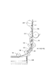
図1は、本発明に係るシート搬送装置を備えた画像形成装置の一例であるフルカラーレーザービームプリンタの構成を示す図である。1はフルカラーレーザービームプリンタ、1Aはフルカラーレーザービームプリンタ本体(以下、プリンタ本体という)、1Bはシートに画像を形成する画像形成部、1Cはシート搬送装置、31は定着ユニットである。
FIG. 1 is a diagram illustrating a configuration of a full-color laser beam printer which is an example of an image forming apparatus including a sheet conveying device according to the present invention.
画像形成部1Bは、スキャナーユニット4と、イエロー(Y)、マゼンタ(M)、シアン(C)及びブラック(Bk)の4色のトナー画像を形成する4個のプロセスカートリッジ2(2Y,2M,2C,2Bk)を備えている。また、画像形成部1Bは、プロセスカートリッジ2の上方に配された中間転写ユニット9を備えている。
The
ここで、各プロセスカートリッジ2は、トナー像を形成する像担持体である感光体ドラム3(3Y,3M,3C,3Bk)を備えている。なお、各感光体ドラム3は、その両端部を支持部材によって回転自在に支持されており、一方の端部に不図示の駆動モータからの駆動力が伝達されることにより、時計周りに回転駆動される。 Each process cartridge 2 includes a photosensitive drum 3 (3Y, 3M, 3C, 3Bk) that is an image carrier that forms a toner image. Each photosensitive drum 3 is rotatably supported at both ends by a support member, and is rotated clockwise by transmitting a driving force from a driving motor (not shown) to one end. Is done.
中間転写ユニット9は、駆動ローラ6、テンションローラ7a及び従動ローラ7bに巻き掛けられた中間転写ベルト5を備えている。また、中間転写ユニット9は、中間転写ベルト5の内側に設けられ、感光体ドラム3に対向した位置で中間転写ベルト5に当接する1次転写ローラ8を備えている。
The
ここで、中間転写ベルト5は、フィルム状部材で構成されると共に各感光体ドラム3に接するように配置され、不図示の駆動部により駆動される駆動ローラ6により矢印A方向(反時計回り)に回転するようになっている。そして、この中間転写ベルト5に1次転写ローラ8によって正極性の転写バイアスを印加することにより、感光体ドラム上の負極性を持つ各色トナー像が順次中間転写ベルト5に多重転写される。これにより、中間転写ベルト上にはフルカラー画像が形成される。 Here, the intermediate transfer belt 5 is composed of a film-like member and is disposed so as to be in contact with each photosensitive drum 3, and is driven in the direction of arrow A (counterclockwise) by a driving roller 6 driven by a driving unit (not shown). It is designed to rotate. Then, by applying a positive transfer bias to the intermediate transfer belt 5 by the primary transfer roller 8, each color toner image having a negative polarity on the photosensitive drum is sequentially transferred to the intermediate transfer belt 5 in a multiple transfer manner. As a result, a full-color image is formed on the intermediate transfer belt.
なお、中間転写ユニット9の駆動ローラ6と対向する位置には、中間転写ベルト上に形成されたフルカラー画像をシートSに転写する2次転写部を構成する2次転写ローラ30が設けられている。そして、シート搬送装置1Cは、この2次転写部にシートを搬送するものである。
A
また、この2次転写ローラ30の上部に定着ユニット31が配置され、この定着ユニット31の上部には排紙ローラ対32及び両面反転部40が配置されている。そして、この両面反転部40は、正逆転可能なシート反転搬送ローラである反転ローラ対41と、切替部材42を備えている。なお、後述するように、両面反転部40により反転されたシートは再度、シート搬送装置1Cにより2次転写部に搬送されるようになっている。
A fixing
なお、図1において、R1は画像形成部1Bにより片面(第1面)に画像が形成されたシートの裏面(第2面)に画像を形成するため、シートの表裏を反転させて再び画像形成部1Bへ導くためのシート搬送路としての再搬送路である。そして、この再搬送路R1にはシート搬送装置1Cを構成する再給紙ローラ対43が設けられている。
In FIG. 1, R1 forms an image on the back side (second side) of the sheet on which the image is formed on one side (first side) by the
次に、このように構成されたフルカラーレーザービームプリンタ1の画像形成動作について説明する。
Next, an image forming operation of the full color
画像形成動作が開始されると、まず不図示のパソコン等からの画像情報に基づきスキャナーユニット4は不図示のレーザ光を照射し、表面が所定の極性・電位に一様に帯電されている感光体ドラム3の表面を順次露光して感光体ドラム上に静電潜像を形成する。この後、この静電潜像をトナーにより現像し、可視化する。 When the image forming operation is started, the scanner unit 4 first irradiates a laser beam (not shown) based on image information from a personal computer (not shown), and the surface is uniformly charged with a predetermined polarity and potential. The surface of the body drum 3 is sequentially exposed to form an electrostatic latent image on the photoreceptor drum. Thereafter, the electrostatic latent image is developed with toner and visualized.
例えば、まず感光体ドラム3Yに、スキャナーユニット4からイエロー成分色の画像信号によるレーザ光を照射し、感光体ドラム3Y上にイエローの静電潜像を形成する。そして、このイエローの静電潜像を、現像器からのイエロートナーにより現像し、イエロートナー像として可視化する。
For example, first, the
次に、このトナー像が感光体ドラム3Yの回転に伴って感光体ドラム3Yと中間転写ベルト5とが当接する1次転写部に到来すると、1次転写ローラ8に印加した1次転写バイアスにより、感光体ドラム上のイエロートナー像が中間転写ベルト5に転写される。
Next, when the toner image arrives at the primary transfer portion where the
次に、中間転写ベルト5のイエロートナー像を担持した部位が移動すると、このときまでに上記と同様な方法で感光体ドラム3M上に形成されたマゼンタトナー像がイエロートナー像上から中間転写ベルト5に転写される。同様に、中間転写ベルト5が移動するにつれて、それぞれ1次転写部においてシアントナー像、ブラックトナー像が、イエロートナー像、マゼンタトナー像上に重ね合わせて転写される。これにより、中間転写ベルト上にフルカラートナー画像が形成される。
Next, when the portion of the intermediate transfer belt 5 carrying the yellow toner image moves, the magenta toner image formed on the
また、このトナー画像形成動作に並行してシート積載部である給紙カセット10に収容されたシートSがシート給送部であるピックアップローラ11により送り出される。そして、シートSは、この後、ピックアップローラ11と分離ローラ12により構成される分離部により1枚ずつに分離されて搬送ローラ対13、中間搬送ローラ対14を経てレジストローラ対15まで搬送される。
In parallel with the toner image forming operation, the sheet S accommodated in the
なお、このときレジストローラ対15は停止しており、このように停止した状態のレジストローラ対15のニップ部にシートを当接させ、シートにループを形成することにより、シートSの斜行を補正することができる。
At this time, the
次に、このようにシートSの斜行を補正した後、レジストローラ対15が、2次転写部で中間転写ベルト上のフルカラートナー像とシートSの位置を合わせるようなタイミングで駆動される。これにより、シートSは2次転写部まで搬送され、2次転写部にて、2次転写ローラ30に印加した2次転写バイアスにより、フルカラートナー像がシートS上に一括して転写される。
Next, after correcting the skew of the sheet S in this way, the
次に、このようにフルカラートナー像が転写されたシートSは、定着ユニット31に搬送され、この定着ユニット31において熱及び圧力を受けて各色のトナーが溶融混色し、シートSにフルカラーの画像として定着される。この後、このように画像が定着されたシートSは、定着ユニット31の下流に設けられた排出ローラ対32によって排紙トレイ33に排紙される。
Next, the sheet S on which the full-color toner image has been transferred in this manner is conveyed to the fixing
一方、シートの両面に画像を形成する場合には、まず両面反転部40の切替部材42を不図示のソレノイド等の駆動機構により時計方向に回動させ、シート搬送経路を排紙ローラ対側から両面反転部側へ変更させる。これにより、片面に画像が形成されたシートSは反転ローラ対41へと導かれ、反転ローラ対41により排紙トレイ33の方向に一定量搬送される。
On the other hand, when images are formed on both sides of a sheet, first, the switching
次に、このようにシートSを一定量搬送した後、反転ローラ対41を逆転させることにより、シートSは再搬送路R1に進入し、やがて再給紙ローラ対43により、ピックアップローラ11からのシート搬送路R2との合流点に達する。この後、シートSは、中間搬送ローラ対14、レジストローラ対15を経て、2次転写部30へ搬送され、この2次転写部30において裏面に画像が転写される。
Next, after the sheet S is conveyed by a certain amount in this way, the reversing
なお、このときまでに切替部材42は、図1に示すシート搬送経路を排紙ローラ対32側へ切り替える位置に切り替わっている。これにより、定着ユニット31で裏面に画像が定着されたシートSは、排紙ローラ対32を経て排紙トレイ33へ積載される。
By this time, the switching
ところで、図2はシート搬送装置1Cの構成を示す図である。図2に示すように、第1シート搬送部を構成するレジストローラ対15は、第1シート搬送回転体である駆動ローラ15aと、駆動ローラ15aと当接してシートを挟持する第1ニップを構成する第1回転体である従動ローラ15bとから成っている。
Incidentally, FIG. 2 is a diagram showing a configuration of the
また、中間搬送ローラ対14は、レジストローラ対15のシート搬送方向上流側に設けられている。そして、この第2シート搬送部を構成する中間搬送ローラ対14は、第2シート搬送回転体である駆動ローラ14aと、駆動ローラ14aと当接してシートを挟持する第2ニップを構成する第2回転体である従動ローラ14bとから成っている。
The intermediate
さらに、ある搬送ローラ対13は、中間搬送ローラ対14のシート搬送方向上流側に設けられている。そして、この第3シート搬送部を構成する搬送ローラ対13は、第3シート搬送回転体である駆動ローラ13aと、駆動ローラ13aと当接してシートを挟持する第3ニップを構成する第3回転体である従動ローラ13bとから成っている。なお、本実施の形態において、搬送ローラ対13、中間搬送ローラ対14及びレジストローラ対15は、一枚のシートを同時に搬送可能な位置に配置されている。
Furthermore, a certain
また、図2に示すように、レジストローラ対15と中間搬送ローラ対14の間には湾曲したシート搬送路を形成する、第1ガイド部材であるレジ前内ガイド21aと、レジ前内ガイド21aと対向して第2ガイド部材であるレジ前外ガイド21bが配置されている。ここで、レジ前外ガイド21bは、中間搬送ローラ対14から搬送されるシートと当接するものであり、円弧形状を有している。そして、このようにレジ前外ガイド21bを円弧形状とすることにより、シートSを湾曲させながらレジストローラ対15に案内するようにしている。
Further, as shown in FIG. 2, a pre-registration
また中間搬送ローラ対14と搬送ローラ対13の間には湾曲したシート搬送路を形成する第3ガイド部材である中間搬送内ガイド20aと、中間搬送内ガイド20aと対向して第4ガイド部材である中間搬送外ガイド20bが配置されている。ここで、中間搬送外ガイド20bは搬送ローラ対13から搬送されるシートと当接するものであり、円弧形状を有している。そして、このように中間搬送外ガイド20bを円弧形状とすることにより、シートSを湾曲させながら中間搬送ローラ対14に案内するようにしている。
An intermediate conveyance
ところで、図2において、V1はレジストローラ対15のシート搬送速度、V2は中間搬送ローラ対14のシート搬送速度、V3は搬送ローラ対13のシート搬送速度である。そして、本実施の形態においては、これら各ローラ対13〜15のシート搬送速度の関係が、V3>V1>V2となるように設定している。なお、ここでのレジストローラ対15のシート搬送速度V1、中間搬送ローラ対14のシート搬送速度V2、搬送ローラ対13のシート搬送速度V3とは夫々のローラ対の周速をさす。
In FIG. 2, V1 is the sheet conveyance speed of the
ここで、レジストローラ対15のシート搬送速度V1、中間搬送ローラ対14のシート搬送速度V2、搬送ローラ対13のシート搬送速度V3とするように設定しても、実際にシートが送られる速度(実シート搬送速度)は、設定通りとならない恐れがある。この理由の一つは、複数のローラ対によってシートが挟持されて搬送される場合には、各搬送ローラ対における搬送力の差によってシートのコシによる搬送ローラ対への押し込みが生じてしまうことである。
Here, even if the sheet conveying
そこで、本実施の形態では、シートのうちの中間搬送ローラ対14からでてくる部分における実シート搬送速度が確実にレジストローラ対15のシート搬送速度V1以下となるようにしている。これは、以下のように構成することで実現している。
Therefore, in this embodiment, the actual sheet conveyance speed in the portion of the sheet that comes from the intermediate
レジストローラ対15のシート搬送速度V1、中間搬送ローラ対14のシート搬送速度V2、搬送ローラ対13のシート搬送速度V3の周速比は、V1を100%とすると、V2は99.1%でありV3は100.9%としている。周速度の関係は、全て同一駆動源より駆動を各搬送ローラ対が得ており、駆動による周速度差は発生しないようにしている。さらにローラ径の公差や摩耗によるローラ径変化においてもV3>V1>V2の関係が保てるようにしている。
The peripheral speed ratio of the sheet conveying speed V1 of the
また、中間搬送ローラ対14と搬送ローラ対13間にある中間搬送外ガイド20bは、中間搬送ローラ対14と搬送ローラ対13との間でシートにループが生じてもシートSのループ部分が接しない構成としている。したがって、V2と、V3との速度関係において発生するシートSのループ部分が中間搬送外ガイド20bに接し、ループの成長が中間搬送外ガイド20bによって規制されることで生じる中間搬送ローラ対14への押し込み力は発生しない。
Further, the intermediate conveyance
言い換えれば、仮にシートSのループ部分が中間搬送外ガイド20bに接した状態でさらにシートのループが成長しようとすると、ループの成長が中間搬送外ガイド20bによって規制されることで中間搬送ローラ対14への押し込み力が増大する恐れがある。
In other words, if the loop of the sheet S further tries to grow in a state where the loop portion of the sheet S is in contact with the intermediate conveyance
しかし、本実施の形態では、シートSのループ部分が中間搬送外ガイド20bに接しないので、このような中間搬送ローラ対14への押し込み力の増大は生じない。したがって、シートのうちの中間搬送ローラ対14から送り出される部分の速度(実シート搬送速度)が増大することがない。
However, in the present embodiment, since the loop portion of the sheet S does not contact the intermediate conveyance
また、各搬送ローラ対は、圧縮バネによってローラ同士が圧接されている。ここで、各ローラ対の搬送力は、圧縮バネのバネ圧やローラ周面の摩擦係数で決定される。各ローラ対の構成が同一であれば、ローラ対の搬送力はローラ対の圧接ばねのバネ力に比例する。本実施の形態では、レジストローラ対15の搬送力をF1、中間搬送ローラ対14の搬送力をF2、搬送ローラ対13の搬送力をF3とすると、F1>F2>F3となるように圧接ばねのバネ力を設定している。
Each pair of transport rollers is pressed against each other by a compression spring. Here, the conveying force of each roller pair is determined by the spring pressure of the compression spring and the friction coefficient of the roller peripheral surface. If the configuration of each roller pair is the same, the conveying force of the roller pair is proportional to the spring force of the pressure contact spring of the roller pair. In the present embodiment, when the conveying force of the
中間搬送ローラ対14と搬送ローラ対13との間でシートSにループが形成された場合、ループが発生したことに起因して、シートのコシによって、中間搬送ローラ対14及び搬送ローラ対13に対して、シートが押し込もうとする力が発生する。このとき、中間搬送ローラ対14の搬送力F2よりも搬送ローラ対13の搬送力F3が小さいので搬送ローラ対13とシートとがスリップし、中間搬送ローラ対13ではシートのスリップは生じない。このためシートのうちの中間搬送ローラ対14から出てくる部分でのシートの実搬送速度は確実にレジストローラ対15のシート搬送速度V1以下(周速以下)となる。
When a loop is formed on the sheet S between the intermediate
次に、このように各ローラ対13〜15のシート搬送速度及び搬送力を設定した場合におけるシートSの挙動について説明する。 Next, the behavior of the sheet S when the sheet conveying speed and conveying force of each of the roller pairs 13 to 15 are set as described above will be described.
まず、搬送ローラ対13と中間搬送ローラ対14との間のシートSの挙動について説明する。
First, the behavior of the sheet S between the
シートSがピックアップローラ11より搬送されると、搬送ローラ対13のニップ部へ搬送され、この搬送ローラ対13により搬送ローラ対13のシート搬送速度V3で搬送される。この後、シートSが搬送ローラ対13により湾曲した中間搬送外ガイド20bに沿って湾曲しながら中間搬送ローラ対14のニップ部まで搬送されると、シートSの先端部の搬送速度は中間搬送ローラ対14のシート搬送速度V2となる。
When the sheet S is conveyed from the pickup roller 11, it is conveyed to the nip portion of the conveying
なお、この時点では、まだシートSの後端部は搬送ローラ対13にニップされた状態となっている。このため、V2<V3という関係より、搬送ローラ対13と中間搬送ローラ対14との間において、シートSは搬送された距離に比例してループが形成される。
At this time, the rear end portion of the sheet S is still nipped by the conveying
ここで、搬送ローラ対13と中間搬送ローラ対14との間のシート搬送路を形成する中間搬送外ガイド20bは外側に膨らんだ形状を有しているので、シートは中間搬送外ガイド側へループし、このループは搬送された距離に比例して大きくなっていく。
Here, since the intermediate conveyance
この後、中間搬送ローラ対14により搬送速度V2で搬送されているシートSがレジストローラ対15のニップ部まで搬送されると、シートSの先端部の搬送速度はレジストローラ対15のシート搬送速度V1となる。
Thereafter, when the sheet S being conveyed at the conveyance speed V2 by the intermediate
なお、この時点ではシートSの一部は、まだ中間搬送ローラ対14にニップされた状態となっている。また、シートのうちの搬送ローラ対13よりも上流側の部分も分離部にある。このため、V1>V2という関係より、即ちレジストローラ対15と中間搬送ローラ対14間のシート搬送速度差により、レジストローラ対15と中間搬送ローラ対14間でシートSが引っ張られる。
At this time, a part of the sheet S is still nipped by the intermediate
ここで、レジストローラ対15の駆動ローラ15a及び従動ローラ15bとの第1ニップのニップ線と、中間搬送ローラ対14の駆動ローラ14a及び従動ローラ14bとの第2ニップのニップ線は一致していない。
Here, the nip line of the first nip between the driving
このため、中間搬送ローラ対14の搬送方向と、レジ前外ガイド21bの外側に膨らんだ形状より、シートSはレジストローラ対15にニップされる前、まずレジ前外ガイド21bに当接し、この後、レジ前外ガイド21bに沿って移動する。そして、このように移動することにより、レジストローラ対15にニップされるとき、シートSにはループが発生している。
For this reason, the sheet S first contacts the pre-registration
このため、レジストローラ対15と中間搬送ローラ対14間でシートSが引っ張られると、シートはレジストローラ対15により、レジストローラ対15と中間搬送ローラ対14との間のループを減少させながらシート搬送速度V1で2次転写部30に搬送される。なお、このようにシートがループを減少させながらシート搬送速度V1で搬送されると、やがて図3の(a)に示すようにレジストローラ対15と中間搬送ローラ対14との間でループがなくなり、シートが一直線に引っ張られるようになる。
For this reason, when the sheet S is pulled between the
このようにシートが一直線に引っ張られるとき、レジストローラ対15の搬送力F1は中間搬送ローラ対14の搬送力F2よりも大きいため、レジストローラ対15のシート搬送速度V1は一定のままである。
Thus, when the sheet is pulled in a straight line, the conveyance force F1 of the
このときの中間搬送ローラ対14の実シート搬送速度をV2’とすると、搬送力の大きなレジストローラ対15によって引張られることによって中間搬送ローラ対14での実シート搬送速度V2’はレジストローラ対15によるシート搬送速度V1と等しくなる。つまり、V2’=V1となる。
If the actual sheet conveyance speed of the intermediate
一方、レジストローラ対15と搬送ローラ対13のシート搬送速度の関係はV3>V1に設定している。このため、レジストローラ対15と中間搬送ローラ対14との間でシートSが引っ張られると、V3>V1(=V2’)という関係から、図3の(b)に示すように中間搬送ローラ対14と搬送ローラ対13間のシートSのループは搬送距離に比例して大きくなる。
On the other hand, the relationship between the sheet conveyance speeds of the
つまり、レジストローラ対15がシートSを一直線に引っ張ると、中間搬送ローラ対14のシート搬送速度はV1(=V2’)となり、V3>V1の関係より、搬送ローラ対13と中間搬送ローラ対14間ではシートのループが発生する。
That is, when the
そして、このように搬送ローラ対13と中間搬送ローラ対14間で、即ちレジストローラ対15の上流でシートがループすることにより、レジストローラ対15には、シートのループ部分よりも上流側にある分離部が搬送抵抗となって影響を与えることがなくなる。この結果、レジストローラ対15は一定のシート搬送速度V1で2次転写部30へシートSを搬送することができる。
Thus, the sheet loops between the conveying
また、既述したようにレジストローラ対15にシートSがニップされる前には、中間搬送ローラ対14の搬送方向とレジ前外ガイド21bの形状よりシートSにループが発生する。ここで、レジストローラ対15にシートSがニップされた後、レジストローラ対15によるシート搬送初期において、レジストローラ対15は、このループを減少させながらシートを搬送する。
As described above, before the sheet S is nipped between the
ここで、各ローラ対13,14,15によりシートが搬送されているときには、既述したように、シートのうちの中間搬送ローラ対14から送り出される部分の実シート搬送速度がレジストローラ対15のシート搬送速度V1以下となるようにしている。これにより、レジストローラ対15へのシートの押し込みは確実に防がれる。したがって、シートのうちのレジストローラ対15より下流部分の実シート搬送速度を一定な速度(V1)にすることができる。
Here, when the sheet is being conveyed by each of the roller pairs 13, 14, 15, as described above, the actual sheet conveyance speed of the portion sent out from the intermediate
さらに、既述したようにレジストローラ対15によるシート搬送初期において、ループを減少させながらシートSを搬送することにより、レジストローラ対15はシートSを2次転写部30へ、一定のシート搬送速度V1を保ちながら搬送することができる。この結果、シート搬送速度の変化に起因する画像伸縮や色ズレ等の発生を防止することができる。
Further, as described above, in the initial stage of sheet conveyance by the
また、シートがループが形成されにくい厚紙等のコシの強い(剛性の大きい)シートの場合でも、中間搬送外ガイド20bやレジ前外ガイド21bが湾曲した形状となっているため、簡単にループを形成することができる。そして、このように厚紙等のシートであっても、簡単にループを形成することができることにより、厚紙等のシートが、そのコシによりレジストローラ対15に押し込まれていくのを防ぐことができる。これにより、厚紙等のシートであっても、安定したシート搬送速度V1で、2次転写部30へ搬送することができる。
Even when the sheet is a strong (rigid) sheet such as thick paper that is difficult to form a loop, the intermediate conveyance
さらに、このようにレジストローラ対15の上流であって、中間搬送ローラ対14と搬送ローラ対13との間では、シートにループが形成されることにより、レジストローラ対15に加わる力として、分離部によるバックテンションは受けない。この結果、ローラ摩耗を軽減することができ、通紙枚数が増加してもシートSを、継続的に安定したシート搬送速度V1で2次転写部30へ搬送することができる。
Further, in this way, upstream of the
なお、レジ前内ガイド21aは、レジストローラ対15と中間搬送ローラ対14の間でシートSが一直線に引っ張られた場合でも、図3の(a)に示すようにシートSと接触しないように曲率を小さくした形状で配置されている。これにより、シートSとレジ前ガイド内21aとの摺擦による抵抗がなくなる。
The pre-registration
また、シート搬送速度の差により搬送ローラ対13と中間搬送ローラ対14との間でシートのループを発生させるV3とV2の関係は、ループが中間搬送外ガイド20bに接触しない速度に設定している。さらに、V3とV1の関係は、ループが大きくなってもループが中間搬送外ガイド20bに接触する前に、シートSが、図3の(b)に示すように搬送ローラ対13を通過するように設定している。
Further, the relationship between V3 and V2 that generates a sheet loop between the
そして、このようにV1〜V3を設定することにより、シートSがレジ前内ガイド21a及び中間搬送外ガイド20bに接触しないようにすることができる。これにより、シートSがレジ前内ガイド21a及び中間搬送外ガイド20bに接触することによる抵抗をなくすことができる。
By setting V1 to V3 in this way, the sheet S can be prevented from contacting the pre-registration
また、本実施の形態において、搬送ローラ対13によるシート搬送速度V3が一番速い構成であるため、ピックアップローラ11と分離ローラ12間で発生するバックテンションを吸収することができる。これにより、レジストローラ対15によるシート搬送速度V1に対する給送部の影響をなくすことができる。
Further, in the present embodiment, since the sheet conveying speed V3 by the conveying
以上説明したように、各ローラ対13〜15のシート搬送速度の関係がV3>V1>V2となるように設定することにより、レジストローラ対15によりシートSを搬送する際、レジストローラ対15よりも上流側で常にシートにループを形成させることができる。つまり、レジストローラ対15によりシートSを搬送する際、レジストローラ対15よりも上流側でシートがループを形成するように各ローラ対13〜15の搬送速度を設定することにより、継続的に安定したシート搬送速度でシートを搬送することができる。また、シートのうちの中間搬送ローラから送り出される部分の実シート搬送速度はレジストローラ対15の速度を超えないので、シートのレジストローラ対15への押し込みも発生しない。
As described above, by setting the relationship between the sheet conveying speeds of the roller pairs 13 to 15 to satisfy V3> V1> V2, when the sheet S is conveyed by the
ところで、これまでの説明においては、各ローラ対13〜15の搬送力をF1>F2>F3とすることで、中間搬送ローラ対14からでてくる部分でのシートの実搬送速度が確実にレジストローラ対15のシート搬送速度V1を超えないようにしている。しかしながら、以下のような構成でも、中間搬送ローラ対14からでてくる部分でのシートの実搬送速度が確実にレジストローラ対15のシート搬送速度V1を超えないようにすることが可能である。
By the way, in the above description, the conveyance force of each of the roller pairs 13 to 15 is F1> F2> F3, so that the actual conveyance speed of the sheet at the portion coming from the intermediate
すなわち、本構成ではレジストローラ対15のシート搬送速度V1、中間搬送ローラ対14のシート搬送速度V2、搬送ローラ対13のシート搬送速度V3の周速比は、V1を100%とすると、V2は99.1%でありV3は100.9%とする。この周速度の関係は、全て同一駆動源より駆動を得ており、駆動による周速度差は発生しない。さらにローラ径の公差や摩耗によるローラ径変化においてもV3>V1>V2の関係が保てるようにする。
That is, in this configuration, the circumferential speed ratio of the sheet conveyance speed V1 of the
また中間搬送ローラ対14と搬送ローラ対13間にある中間搬送外ガイド20bを、中間搬送ローラ対14と搬送ローラ対13との間にループが生じてもシートSが接しない構成とする。これにより、上記のような周速度の関係において、シートSのループが発生してもループしたシートSが中間搬送外ガイド20bに接することはないので、中間搬送外ガイド20bによってシートSに中間搬送ローラ対14へ押し込む力が発生することはない。
Further, the intermediate conveyance
なお、中間搬送ローラ対14の駆動ローラ14aには、ラチェット機構が組み込まれている。このラチェット機構は駆動ローラ14aに駆動列からの反時計回り(図中矢印方向)のみ駆動が伝える構成である。ラチェット機構には圧縮バネが設けられている。この圧縮バネのバネ圧は上記各ローラ対13〜15の周速度(搬送速度)の関係において中間搬送ローラ対14と搬送ローラ対13の搬送速度差より生じるシートのループによるコシの押し込み力に抗するように設定している。
A ratchet mechanism is incorporated in the
一方、ラチェット機構の圧縮バネのバネ圧は、レジストローラ対15と中間搬送ローラ対14の搬送速度差によるシートの引張り力に対しては連れまわりをするバネ圧に設定している。このような構成とすることで、既述した構成と同様の効果を有することが可能である。
On the other hand, the spring pressure of the compression spring of the ratchet mechanism is set to a spring pressure that rotates with respect to the tensile force of the sheet due to the difference in conveyance speed between the
ところで、これまではシート搬送装置1Cのシートの第1面に画像を形成する場合の搬送速度制御について述べてきた。しかし、本実施の形態においては、シートの両面に画像を形成する場合にシートを搬送する箇所においても上述の搬送速度制御を適用している。
By the way, the conveyance speed control when forming an image on the first surface of the sheet of the
次に、シートの両面に画像を形成する場合に使用する再搬送路でのシート搬送について図4乃至図6を用いて説明する。 Next, sheet conveyance on the re-conveying path used when images are formed on both sides of the sheet will be described with reference to FIGS.
図4において、50a、50bは上下方向に延びた再搬送路R1の中間搬送ローラ対14と再給紙ローラ対43の間の部分を形成する第3ガイド部材である再給紙内ガイド及び第4ガイド部材である再給紙外ガイドである。
In FIG. 4,
Rはシートを2次転写部30へ搬送するためシート搬送路であり、このシート搬送路Rと再搬送路R1とにより、再給紙ローラ対43とレジストローラ対15との間の搬送経路はU字形状となっている。
R is a sheet conveyance path for conveying the sheet to the
また、43は反転したシートSを再度、2次転写部に向かわせる第3シート搬送部を構成する再給紙ローラ対である。そして、この再給紙ローラ対43は、第3シート搬送回転体である駆動ローラ43aと、駆動ローラ43aと当接してシートを挟持する第3ニップを構成する第3回転体である従動ローラ43bとから成っている。
ここで、再給紙外ガイド50bは、既述したように片面に画像が形成された後、両面反転部40により反転された状態で再給紙ローラ対43から搬送されるシートと当接するものであり、外側に膨らんだ円弧形状を有している。そして、このように再給紙外ガイド50bを外側に膨らんだ円弧形状とすることにより、シートSを湾曲させながら再給紙ローラ対43に案内するようにしている。
Here, the
図5は、片面に画像が形成されたシートSが再給紙ローラ対43により、ピックアップローラ11からのシート搬送経路R2との合流点に達した後、中間搬送ローラ対14、レジストローラ対15へ搬送されたときの状態を示している。
In FIG. 5, after the sheet S having an image formed on one side reaches the junction with the sheet conveyance path R <b> 2 from the pickup roller 11 by the
図5において、V4は再給紙ローラ対43におけるシート搬送速度である。そして、本実施の形態において、再給紙ローラ対43のシート搬送速度V4と、レジストローラ対15のシート搬送速度V1と、中間搬送ローラ対14のシート搬送速度V2との関係を、V4>V1>V2となるように設定している。
In FIG. 5, V <b> 4 is the sheet conveyance speed in the
また各搬送ローラ対14,15,43のニップ力は図示しない圧縮バネによって与えられている。レジストローラ対15の搬送力をF1、中間搬送ローラ対14の搬送力をF2、再給紙ローラ対43の搬送力をF4とすると、F1>F2>F4となるように設定している。
Further, the nip force of each conveying
再給紙ローラ対43と中間搬送ローラ対14との速度差によってシートSがループした場合、シートのコシによって再給紙ローラ対43および中間搬送ローラ対14に対してシートが押し込もうとする力が発生する。ここで、再給紙ローラ対43の搬送力F4が、中間搬送ローラ対14の搬送力F2よりも小さいので、再給紙ローラ対43側へシートが押し込まれる。この結果、中間搬送ローラ対14側へのシートの押し込みは生じないので、シートのうちの中間搬送ローラ対14から出てくる部分の実搬送速度は、確実にレジストローラ対15のシート搬送速度V1以下となる。
When the sheet S loops due to a difference in speed between the
次に、このように各ローラ対14,15,43のシート搬送速度及び搬送力を設定した場合におけるシートSの挙動について説明する。
Next, the behavior of the sheet S when the sheet conveying speed and conveying force of each
両面に画像を形成するため、シートSが両面反転ローラ対41より再給紙ローラ対43のニップ部へ搬送されると、シートSの搬送速度は再給紙ローラ対43のシート搬送速度V4となる。この後、再給紙ローラ対43がシートSを中間搬送ローラ対14のニップ部まで搬送すると、シートSの先端部の搬送速度は中間搬送ローラ対14のシート搬送速度V2となる。
In order to form an image on both sides, when the sheet S is conveyed from the duplex reversing
この時点では、シートSの一部は再給紙ローラ対43にニップされた状態となっているため、V2<V4の関係より、再給紙ローラ対43と中間搬送ローラ対14との間において、シートSは搬送された距離に比例して再給紙外ガイド側へループが形成される。
At this time, a part of the sheet S is nipped by the
次に、中間搬送ローラ対14によりシート搬送速度V2で搬送されたシートSがレジストローラ対15のニップ部まで搬送されると、シートSの先端部はレジストローラ対15によりシート搬送速度V1で搬送されるようになる。
Next, when the sheet S conveyed at the sheet conveyance speed V2 by the intermediate
この時点では、シートSの一部は中間搬送ローラ対14にニップされた状態となっているため、V1>V2の関係より、レジストローラ対15と中間搬送ローラ対14間のシートSが、図6の(a)に示すように一直線に引っ張られるようになる。そして、シートSが一直線に引っ張られるとき、レジストローラ対15の搬送力は中間搬送ローラ対14の搬送力F2よりも大きいため、レジストローラ対15のシート搬送速度V1は一定のままである。
At this point, since a part of the sheet S is nipped by the intermediate
このときの中間搬送ローラ対14での実シート搬送速度をV2’とすると、搬送力の大きなレジストローラ対15によって引張られることによって中間搬送ローラ対14での実シート搬送速度V2’はレジストローラ対15のシート搬送速度V1と等しくなる。つまり、V2’=V1となる。
If the actual sheet conveyance speed at the intermediate
一方、レジストローラ対15と再給紙ローラ対43のシート搬送速度の関係はV4>V1と設定している。このため、レジストローラ対15と中間搬送ローラ対14の間でシートSが引っ張られると、V4>V1(=V2’)という関係から、図6の(b)に示すように中間搬送ローラ対14と再給紙ローラ対43間のシートSのループは搬送距離に比例して大きくなる。
On the other hand, the relationship between the sheet conveyance speeds of the
つまり、レジストローラ対15がシートSを一直線に引っ張ると、中間搬送ローラ対14のシート搬送速度はV1(=V2’)となり、V4>V1の関係より、再給紙ローラ対43と中間搬送ローラ対14との間でシートのループが発生する。
That is, when the
そして、このように再給紙ローラ対43と中間搬送ローラ対14間で、即ちレジストローラ対15の上流でシートがループすることにより、レジストローラ対15に搬送抵抗などの影響を与えることがなくなる。この結果、レジストローラ対15は一定のシート搬送速度V1で2次転写部30へシートSを搬送することができる。
Thus, the sheet is looped between the
なお、シート搬送速度の差により再給紙ローラ対43と中間搬送ローラ対14との間でシートのループを発生させるV4とV2の関係は、ループが再給紙外ガイド50bに接触しない速度に設定している。さらに、V4とV1の関係は、ループが大きくなってもループが中間搬送外ガイド20bに接触する前に、シートSが、図6の(b)に示すように再給紙ローラ対43を通過するように設定している。言い換えると、再給紙ローラ対43と中間搬送ローラ対14との間でシートにループが形成されても、シートのループ部分と接しない位置に再給紙外ガイド50bを設けている。
Note that the relationship between V4 and V2 that generates a sheet loop between the
これにより、シートSが再給紙外ガイド50b及びレジ前内ガイド21aに接触しないようにすることができ、シートSが再給紙外ガイド50b及びレジ前内ガイド21aに接触することによる抵抗をなくすことができる。また、ループの成長が再給紙外ガイド50bに規制されることで中間搬送ローラ対14にシートが押し込んでしまうことがない。
As a result, the sheet S can be prevented from coming into contact with the
なお、これまでの説明においては、感光体ドラム3に形成されたトナー像を中間転写ベルト5に転写した後、2次転写部でシートに転写する方式の画像形成装置について説明したが、本発明は、これに限らない。例えば、感光体ドラム3に形成されたトナー像を直接、転写部でシートに転写する方式の画像形成装置にも適用することができる。 In the above description, the image forming apparatus of the type in which the toner image formed on the photosensitive drum 3 is transferred to the intermediate transfer belt 5 and then transferred to the sheet at the secondary transfer unit has been described. Is not limited to this. For example, the present invention can be applied to an image forming apparatus in which a toner image formed on the photosensitive drum 3 is directly transferred to a sheet by a transfer unit.
また、これまでの説明においては、画像形成装置に設けられるシート搬送装置について述べてきたが、本発明はこれに限定されるものではない。例えば、画像読取装置などに用いられ、シートである原稿を、原稿画像を読み取る画像読取部に搬送するシート搬送装置の一例である原稿自動給送装置に適用することもできる。 In the description so far, the sheet conveying device provided in the image forming apparatus has been described, but the present invention is not limited to this. For example, the present invention can be applied to an automatic document feeder that is an example of a sheet conveying device that is used in an image reading device or the like and conveys a document as a sheet to an image reading unit that reads a document image.
1 フルカラーレーザービームプリンタ
1A フルカラーレーザービームプリンタ本体
1B 画像形成部
1C シート搬送装置
3 感光体ドラム
9 中間転写ユニット
10 給紙カセット
11 ピックアップローラ
13 搬送ローラ対
14 中間搬送ローラ対
15 レジストローラ対
20a 中間搬送内ガイド
20b 中間搬送外ガイド
21a レジ前内ガイド
21b レジ前外ガイド
40 両面反転部
43 再給紙ローラ対
50a 再給紙内ガイド
50b 再給紙外ガイド
F1 レジストローラ対の搬送力
F2 中間搬送ローラ対の搬送力
F3 搬送ローラ対の搬送力
F4 再給紙ローラ対の搬送力
R シート搬送路
R1 再搬送路
S シート
V1 レジストローラ対のシート搬送速度
V2 中間搬送ローラ対のシート搬送速度
V3 搬送ローラ対のシート搬送速度
V4 再給紙ローラ対のシート搬送速度
DESCRIPTION OF
Claims (11)
前記第1シート搬送回転体のシート搬送方向上流側に設けられた第2シート搬送回転体と、
前記第2シート搬送回転体のシート搬送方向上流側に設けられた第3シート搬送回転体と、を備え、
前記第1シート搬送回転体と前記第2シート搬送回転体と前記第3シート搬送回転体とは同時に一枚のシートを搬送可能であって、前記第1シート搬送回転体の周速をV1、前記第2シート搬送回転体の周速をV2、前記第3シート搬送回転体の周速をV3としたとき、V1、V2及びV3の関係を、V3>V1>V2とし、且つ、前記第2シート搬送回転体から送り出される部分でのシートの速度が前記第1シート搬送回転体の周速以下となるようにしたことを特徴とするシート搬送装置。 A first sheet conveying rotating body;
A second sheet conveying rotating body provided on the upstream side in the sheet conveying direction of the first sheet conveying rotating body;
A third sheet conveying rotating body provided on the upstream side in the sheet conveying direction of the second sheet conveying rotating body,
The first sheet transport rotator, the second sheet transport rotator, and the third sheet transport rotator are capable of transporting one sheet at a time, and the peripheral speed of the first sheet transport rotator is V1, When the peripheral speed of the second sheet transport rotator is V2, and the peripheral speed of the third sheet transport rotator is V3, the relationship between V1, V2 and V3 is V3>V1> V2, and the second A sheet conveying apparatus characterized in that a sheet speed at a portion fed from the sheet conveying rotating body is equal to or lower than a peripheral speed of the first sheet conveying rotating body.
前記ガイド部材を、前記第2シート搬送回転体と前記第3シート搬送回転体とでシートが搬送される際に、前記第2シート搬送回転体と前記第3シート搬送回転体との間でシートに撓みが生じても、該シートのループ部分と接しない位置に設けたことを特徴とする請求項1記載のシート搬送装置。 A curved guide member that is provided between the second sheet transport rotator and guides a sheet transported by the third sheet transport rotator to the second sheet transport rotator. Prepared,
When the sheet is transported between the second sheet transport rotator and the third sheet transport rotator, the guide member is moved between the second sheet transport rotator and the third sheet transport rotator. 2. The sheet conveying apparatus according to claim 1, wherein the sheet conveying apparatus is provided at a position that does not contact the loop portion of the sheet even if the sheet is bent.
前記第2シート搬送回転体と当接して第2ニップを構成する第2回転体と、
を有し、
前記第2ニップのニップ線は前記第1ニップのニップ線と一致しないことを特徴とする請求項1ないし3の何れか1項に記載のシート搬送装置。 A first rotating body that contacts the first sheet conveying rotating body to form a first nip;
A second rotating body that contacts the second sheet conveying rotating body to form a second nip;
Have
4. The sheet conveying apparatus according to claim 1, wherein a nip line of the second nip does not coincide with a nip line of the first nip. 5.
前記第2シート搬送回転体の搬送力が前記第3シート搬送回転体の搬送力よりも大きいことを特徴とする請求項1ないし4の何れか1項に記載のシート搬送装置。 The conveying force of the first sheet conveying rotating body is greater than the conveying force of the second sheet conveying rotating body,
The sheet conveying apparatus according to any one of claims 1 to 4, wherein a conveying force of the second sheet conveying rotating body is larger than a conveying force of the third sheet conveying rotating body.
前記第2シート搬送回転体とでシートを挟持して搬送する第2シート搬送部を構成する第2回転体と、
前記第3シート搬送回転体とでシートを挟持して搬送する第3シート搬送部を構成する第3回転体と、
を有し、
前記第1シート搬送部の搬送力が前記第2シート搬送部の搬送力よりも大きく、前記第2シート搬送部の搬送力が前記第3シート搬送部の搬送力よりも大きいことを特徴とする請求項1ないし3の何れか1項に記載のシート搬送装置。 A first rotating body constituting a first sheet conveying section for nipping and conveying a sheet with the first sheet conveying rotating body;
A second rotating body constituting a second sheet conveying section for nipping and conveying the sheet with the second sheet conveying rotating body;
A third rotating body constituting a third sheet conveying section for nipping and conveying the sheet with the third sheet conveying rotating body;
Have,
The conveyance force of the first sheet conveyance unit is larger than the conveyance force of the second sheet conveyance unit, and the conveyance force of the second sheet conveyance unit is larger than the conveyance force of the third sheet conveyance unit. The sheet conveying apparatus according to any one of claims 1 to 3.
前記第1シート搬送回転体のシート搬送方向上流側に設けられた第2シート搬送回転体と、
前記第2シート搬送回転体のシート搬送方向上流側に設けられた第3シート搬送回転体と、
前記第2シート搬送回転体と前記第3シート搬送回転体との間に設けられ、前記第3シート搬送回転体により搬送されるシートを前記第2シート搬送回転体にガイドするガイド部材と、
を備え、
前記第1シート搬送回転体によりシートを搬送する際、前記第1シート搬送回転体よりもシート搬送方向上流側でシートがループを形成するよう前記第1シート搬送回転体の周速をV1、前記第2シート搬送回転体の周速をV2、前記第3シート搬送回転体の周速をV3としたとき、V1、V2及びV3の関係を、V3>V1>V2とし、
前記第2シート搬送回転体と前記第3シート搬送回転体とでシートが搬送される際に、前記第2シート搬送回転体と前記第3シート搬送回転体との間でシートにループが生じても、該シートのループ部分と接しない位置に前記ガイド部材を設けたことを特徴とするシート搬送装置。 A first sheet conveying rotating body;
A second sheet conveying rotating body provided on the upstream side in the sheet conveying direction of the first sheet conveying rotating body;
A third sheet conveying rotating body provided on the upstream side in the sheet conveying direction of the second sheet conveying rotating body;
A guide member that is provided between the second sheet transport rotator and guides a sheet transported by the third sheet transport rotator to the second sheet transport rotator;
With
When the sheet is conveyed by the first sheet conveying rotator, the peripheral speed of the first sheet conveying rotator is set to V1, so that the sheet forms a loop upstream of the first sheet conveying rotator in the sheet conveying direction. When the peripheral speed of the second sheet transport rotator is V2 and the peripheral speed of the third sheet transport rotator is V3, the relationship between V1, V2 and V3 is V3>V1> V2,
When a sheet is transported between the second sheet transport rotating body and the third sheet transport rotating body, a loop occurs in the sheet between the second sheet transport rotating body and the third sheet transport rotating body. The sheet conveying apparatus, wherein the guide member is provided at a position not in contact with the loop portion of the sheet.
前記像担持体に形成されたトナー像をシートに転写する転写部と、
前記転写部にシートを搬送する請求項1乃至8のいずれか1項に記載のシート搬送装置と、を備えたことを特徴とする画像形成装置。 An image carrier on which a toner image is formed;
A transfer unit for transferring the toner image formed on the image carrier to a sheet;
An image forming apparatus comprising: the sheet conveying apparatus according to claim 1, which conveys a sheet to the transfer unit.
前記シート積載部に積載されたシートを送り出すシート給送部と、を備え、
前記第1シート搬送回転体は、シートを前記像担持体上のトナー像に合わせて前記転写部に搬送するものであり、前記第3シート搬送回転体は、前記シート給送部より給送されたシートを前記第2シート搬送回転体へ受け渡すものであることを特徴とする請求項9記載の画像形成装置。 A sheet stacking unit;
A sheet feeding unit that feeds out the sheets stacked on the sheet stacking unit,
The first sheet conveying rotating body conveys a sheet to the transfer unit in accordance with a toner image on the image carrier, and the third sheet conveying rotating body is fed from the sheet feeding unit. The image forming apparatus according to claim 9, wherein the transferred sheet is transferred to the second sheet conveying rotating body .
前記第3シート搬送回転体は、前記再搬送路に設けられ、前記第1面にトナー像が転写されたシートを前記第2シート搬送回転体へ受け渡すものであることを特徴とする請求項9記載の画像形成装置。
A re-conveying path that reverses the sheet on which the toner image is transferred to the first surface by the transfer unit, and is directed again to the transfer unit;
The third sheet conveying rotator is provided in the re-conveying path and delivers a sheet having a toner image transferred to the first surface to the second sheet conveying rotator. The image forming apparatus according to 9.
Priority Applications (1)
| Application Number | Priority Date | Filing Date | Title |
|---|---|---|---|
| JP2008085291A JP5067874B2 (en) | 2007-03-30 | 2008-03-28 | Sheet conveying apparatus and image forming apparatus |
Applications Claiming Priority (3)
| Application Number | Priority Date | Filing Date | Title |
|---|---|---|---|
| JP2007095290 | 2007-03-30 | ||
| JP2007095290 | 2007-03-30 | ||
| JP2008085291A JP5067874B2 (en) | 2007-03-30 | 2008-03-28 | Sheet conveying apparatus and image forming apparatus |
Publications (3)
| Publication Number | Publication Date |
|---|---|
| JP2008273735A JP2008273735A (en) | 2008-11-13 |
| JP2008273735A5 JP2008273735A5 (en) | 2011-05-12 |
| JP5067874B2 true JP5067874B2 (en) | 2012-11-07 |
Family
ID=39792903
Family Applications (1)
| Application Number | Title | Priority Date | Filing Date |
|---|---|---|---|
| JP2008085291A Active JP5067874B2 (en) | 2007-03-30 | 2008-03-28 | Sheet conveying apparatus and image forming apparatus |
Country Status (2)
| Country | Link |
|---|---|
| US (1) | US7810811B2 (en) |
| JP (1) | JP5067874B2 (en) |
Families Citing this family (15)
| Publication number | Priority date | Publication date | Assignee | Title |
|---|---|---|---|---|
| US8387978B2 (en) * | 2006-08-31 | 2013-03-05 | Seiko Epson Corporation | Recording apparatus and medium transporting method |
| JP5419533B2 (en) * | 2009-04-30 | 2014-02-19 | キヤノン株式会社 | Image forming apparatus |
| JP2011057412A (en) * | 2009-09-11 | 2011-03-24 | Ricoh Co Ltd | Carrying device, image forming device, carrying object medium carrying method and program |
| KR20120035520A (en) * | 2010-10-05 | 2012-04-16 | 삼성전자주식회사 | Image forming apparatus |
| JP5874346B2 (en) * | 2011-11-25 | 2016-03-02 | ブラザー工業株式会社 | Conveying apparatus and image recording apparatus |
| JP2014114152A (en) | 2012-12-12 | 2014-06-26 | Canon Inc | Sheet transport device and image formation apparatus |
| JP6071526B2 (en) * | 2012-12-20 | 2017-02-01 | キヤノン株式会社 | Sheet transport device |
| JP6194608B2 (en) * | 2013-03-27 | 2017-09-13 | セイコーエプソン株式会社 | Recording device |
| JP6052115B2 (en) * | 2013-09-12 | 2016-12-27 | カシオ電子工業株式会社 | Printing device |
| US9108811B1 (en) * | 2014-10-09 | 2015-08-18 | Xerox Corporation | Variably changing nip feeding speeds to maintain optimal sheet buckle |
| JP6717114B2 (en) * | 2016-08-22 | 2020-07-01 | コニカミノルタ株式会社 | Image forming device |
| JP7083237B2 (en) * | 2017-07-28 | 2022-06-10 | 理想科学工業株式会社 | Paper feed device |
| JP7020358B2 (en) * | 2018-09-28 | 2022-02-16 | 沖電気工業株式会社 | Print medium feeding device and image forming device |
| JP7381216B2 (en) * | 2019-04-05 | 2023-11-15 | キヤノン株式会社 | Recording device and control method |
| JP7317569B2 (en) * | 2019-05-08 | 2023-07-31 | シャープ株式会社 | Paper transport device and image forming device |
Family Cites Families (16)
| Publication number | Priority date | Publication date | Assignee | Title |
|---|---|---|---|---|
| JPS6279150A (en) * | 1985-09-30 | 1987-04-11 | Mita Ind Co Ltd | Conveying device for copying paper |
| JPS62244846A (en) * | 1986-04-16 | 1987-10-26 | Ricoh Co Ltd | Paper feeding device |
| JP2853391B2 (en) * | 1991-08-06 | 1999-02-03 | 富士ゼロックス株式会社 | Image reading device |
| US5393044A (en) * | 1992-12-04 | 1995-02-28 | Sharp Kabushiki Kaisha | Paper feeder |
| DE4243222C2 (en) * | 1992-12-19 | 1997-07-03 | Roland Man Druckmasch | Device for transporting and slowing down folding products |
| US5651539A (en) * | 1995-01-10 | 1997-07-29 | Mita Industrial Co., Ltd. | Image forming apparatus with smooth transfer sheet roller transport |
| JPH1035941A (en) * | 1996-07-18 | 1998-02-10 | Mita Ind Co Ltd | Transfer paper carrying mechanism of image forming device |
| DE19753419C1 (en) * | 1997-12-02 | 1999-02-18 | Siemens Ag | Speed adjuster for flat article conveyor |
| JP3661839B2 (en) * | 1999-08-17 | 2005-06-22 | 株式会社Pfu | Paper separating device and optical reader |
| JP4428872B2 (en) | 2001-02-23 | 2010-03-10 | キヤノン株式会社 | Image forming apparatus |
| JP2002362776A (en) | 2001-06-11 | 2002-12-18 | Canon Inc | Image forming device |
| US6460687B1 (en) * | 2002-02-01 | 2002-10-08 | Phogenix Imaging, Llc | Buffer with service loop and method |
| US6554216B1 (en) * | 2002-02-01 | 2003-04-29 | Phogenix Imaging, Llc | Buffer with service loop and method |
| US6965742B2 (en) * | 2002-11-08 | 2005-11-15 | Canon Kabushiki Kaisha | Image forming apparatus |
| JP4184904B2 (en) * | 2003-09-03 | 2008-11-19 | 株式会社東芝 | Paper sheet separating and conveying device |
| US7280798B2 (en) * | 2004-03-09 | 2007-10-09 | Canon Kabushiki Kaisha | Image forming apparatus with conveying device urging a recording material toward a charge eliminating member |
-
2008
- 2008-03-24 US US12/053,972 patent/US7810811B2/en active Active
- 2008-03-28 JP JP2008085291A patent/JP5067874B2/en active Active
Also Published As
| Publication number | Publication date |
|---|---|
| JP2008273735A (en) | 2008-11-13 |
| US7810811B2 (en) | 2010-10-12 |
| US20080237967A1 (en) | 2008-10-02 |
Similar Documents
| Publication | Publication Date | Title |
|---|---|---|
| JP5067874B2 (en) | Sheet conveying apparatus and image forming apparatus | |
| JP5087948B2 (en) | Image forming apparatus capable of duplex recording | |
| CN109298610B (en) | Image forming apparatus with a plurality of image forming units | |
| US8452223B2 (en) | Image forming apparatus with sheet transport control timing changed according to length of transported sheet | |
| US10214373B2 (en) | Sheet feeding device and image forming apparatus | |
| JP5455723B2 (en) | Sheet skew correction device and image forming apparatus | |
| US20110076035A1 (en) | Image forming apparatus and sheet conveying method | |
| JP5414237B2 (en) | Image forming apparatus | |
| JP7019386B2 (en) | Sheet feeding device and image forming device | |
| JP2016179868A (en) | Paper feeding device and control program of paper feeding device | |
| JP4950654B2 (en) | Image forming apparatus | |
| JP2010155681A (en) | Sheet ejecting device and image forming device | |
| JP6929132B2 (en) | Sheet transfer device and image forming device | |
| JP2014214013A (en) | Recording medium feeder, and image forming apparatus including the same | |
| JP3315521B2 (en) | Image forming device | |
| JP5029410B2 (en) | Image forming apparatus and paper feeding mechanism | |
| JP5279612B2 (en) | Sheet conveying apparatus and image forming apparatus | |
| JP2006036439A (en) | Sheet feeding device, image forming device, and image reader | |
| JP6750874B2 (en) | Sheet feeding apparatus and image forming apparatus | |
| JP2002274702A (en) | Conveying method for cardboard and image forming device | |
| JP4858175B2 (en) | Recording medium supply device and image forming apparatus | |
| JP2007297145A (en) | Image forming device | |
| JP2011257683A (en) | Image forming apparatus | |
| JP2008044747A (en) | Sheet conveying device and image forming device | |
| JP2006151563A (en) | Image forming device |
Legal Events
| Date | Code | Title | Description |
|---|---|---|---|
| A521 | Request for written amendment filed |
Free format text: JAPANESE INTERMEDIATE CODE: A523 Effective date: 20110324 |
|
| A621 | Written request for application examination |
Free format text: JAPANESE INTERMEDIATE CODE: A621 Effective date: 20110324 |
|
| RD05 | Notification of revocation of power of attorney |
Free format text: JAPANESE INTERMEDIATE CODE: A7425 Effective date: 20120125 |
|
| RD03 | Notification of appointment of power of attorney |
Free format text: JAPANESE INTERMEDIATE CODE: A7423 Effective date: 20120203 |
|
| A977 | Report on retrieval |
Free format text: JAPANESE INTERMEDIATE CODE: A971007 Effective date: 20120705 |
|
| TRDD | Decision of grant or rejection written | ||
| A01 | Written decision to grant a patent or to grant a registration (utility model) |
Free format text: JAPANESE INTERMEDIATE CODE: A01 Effective date: 20120717 |
|
| A01 | Written decision to grant a patent or to grant a registration (utility model) |
Free format text: JAPANESE INTERMEDIATE CODE: A01 |
|
| A61 | First payment of annual fees (during grant procedure) |
Free format text: JAPANESE INTERMEDIATE CODE: A61 Effective date: 20120809 |
|
| FPAY | Renewal fee payment (event date is renewal date of database) |
Free format text: PAYMENT UNTIL: 20150824 Year of fee payment: 3 |
|
| R151 | Written notification of patent or utility model registration |
Ref document number: 5067874 Country of ref document: JP Free format text: JAPANESE INTERMEDIATE CODE: R151 |
|
| FPAY | Renewal fee payment (event date is renewal date of database) |
Free format text: PAYMENT UNTIL: 20150824 Year of fee payment: 3 |