JP5067796B2 - トリガー式液体噴出器 - Google Patents
トリガー式液体噴出器 Download PDFInfo
- Publication number
- JP5067796B2 JP5067796B2 JP2007251466A JP2007251466A JP5067796B2 JP 5067796 B2 JP5067796 B2 JP 5067796B2 JP 2007251466 A JP2007251466 A JP 2007251466A JP 2007251466 A JP2007251466 A JP 2007251466A JP 5067796 B2 JP5067796 B2 JP 5067796B2
- Authority
- JP
- Japan
- Prior art keywords
- cylinder
- trigger
- suction valve
- plunger
- type liquid
- Prior art date
- Legal status (The legal status is an assumption and is not a legal conclusion. Google has not performed a legal analysis and makes no representation as to the accuracy of the status listed.)
- Expired - Fee Related
Links
- 239000007788 liquid Substances 0.000 title claims description 53
- 238000002347 injection Methods 0.000 claims description 37
- 239000007924 injection Substances 0.000 claims description 37
- 229920001971 elastomer Polymers 0.000 claims description 3
- 239000000806 elastomer Substances 0.000 claims description 3
- 239000012530 fluid Substances 0.000 claims description 2
- 238000011144 upstream manufacturing Methods 0.000 claims description 2
- 230000001960 triggered effect Effects 0.000 claims 1
- 238000009825 accumulation Methods 0.000 description 6
- 238000012856 packing Methods 0.000 description 3
- 230000002093 peripheral effect Effects 0.000 description 3
- 229920002379 silicone rubber Polymers 0.000 description 2
- 239000004945 silicone rubber Substances 0.000 description 2
- 230000007423 decrease Effects 0.000 description 1
- 230000002950 deficient Effects 0.000 description 1
- 238000007789 sealing Methods 0.000 description 1
- 239000002699 waste material Substances 0.000 description 1
Images


Landscapes
- Reciprocating Pumps (AREA)
- Containers And Packaging Bodies Having A Special Means To Remove Contents (AREA)
Description
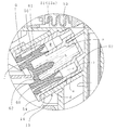
A…装着キャップ
2…周壁,3…フランジ
B…本体
10…装着基部,11…縦筒,12…射出筒,13…シリンダ,13a …補助シリンダ,
14…筒部,15…シール筒,16…係止突条,17…吸込み弁座,19…連通窓,
p…パッキン,R…シリンダ室
C…吸上げパイプ
D…吸込み弁部材
20…嵌着筒,21…弾性板部,22…吸込み弁体,23…吸込み弁
E…スピン部材
30…柱状部,31…円弧板状壁,32…凹溝,33…後壁部,34…弾性板部,
35…吸込み弁体 F…吐出弁体
40…嵌合筒,41…弁板,42…吐出弁
G…シリンダ部材
50…外筒,51…内筒,52…後壁部,53…連通管,a…第1開口,b…第2開口,
c…通路,d…可動環状空間,e…導入凹部,f…凹部
H…プランジャ
60…基部,61…外側摺動部,62…内側摺動部,s…コイルスプリング
I…トリガー
J…ノズル
70…回動筒,71…前板,72…案内筒,73…噴出孔,74…凹溝部,75…邪魔板
K…筒体
80…筒部,81…係合リブ,82…連通路,83…吸込み弁座
Claims (3)
- 本体(B)内部に備えた液流路の中途にシリンダ(13)を連通させるとともに、シリンダ(13)内を摺動するプランジャ(H)の押込み操作を行うトリガー(I)を備え、液流路内に設けた吸込み弁(23)との間にシリンダ(13)内と連通する加圧領域を画成して所定液圧で開弁する蓄圧式の吐出弁(42)を備え、トリガー(I)の操作により容器体内の液を液流路終端のノズル(J)より噴出する如く構成したトリガー式液体噴出器に於いて、プランジャ(H)の押込み状態ではシリンダ(13)内と容器体内とを連通し、常時は連通が遮断される連絡路を設け、前記吸込み弁(23)を、射出筒(12)内に嵌着固定した筒体(K)先端の吸込み弁座(83)に、常時上流側へ付勢させた吸込み弁体(35)を圧接させて構成し、筒体(K)と射出筒(12)との間にシリンダ室R内と射出筒(12)内とを連通する連通路(82)を形成したことを特徴とするトリガー式液体噴出器。
- シリンダ(13)を内外二層構造で構成し、前記連絡路を、容器体内と連通するシリンダ(13)外表面の第1開口(a)及びシリンダ(13)内表面の第2開口(b)を連通する通路(c)と、該通路(c)と常時連通し、プランジャ(H)外面とシリンダ(13)内面とで画成した可動環状空間(d)と、シリンダ(13)内面に凹設した導入凹部(e)とで構成し、プランジャ(H)の押込み状態でシリンダ(13)内と可動環状空間(d)とが導入凹部(e)を介して連通する如く構成した請求項1記載のトリガー式液体噴出器。
- 筒体(K)をエラストマーで形成した請求項1又は請求項2のいずれかに記載のトリガー式液体噴出器。
Priority Applications (1)
| Application Number | Priority Date | Filing Date | Title |
|---|---|---|---|
| JP2007251466A JP5067796B2 (ja) | 2007-09-27 | 2007-09-27 | トリガー式液体噴出器 |
Applications Claiming Priority (1)
| Application Number | Priority Date | Filing Date | Title |
|---|---|---|---|
| JP2007251466A JP5067796B2 (ja) | 2007-09-27 | 2007-09-27 | トリガー式液体噴出器 |
Publications (2)
| Publication Number | Publication Date |
|---|---|
| JP2009078256A JP2009078256A (ja) | 2009-04-16 |
| JP5067796B2 true JP5067796B2 (ja) | 2012-11-07 |
Family
ID=40653416
Family Applications (1)
| Application Number | Title | Priority Date | Filing Date |
|---|---|---|---|
| JP2007251466A Expired - Fee Related JP5067796B2 (ja) | 2007-09-27 | 2007-09-27 | トリガー式液体噴出器 |
Country Status (1)
| Country | Link |
|---|---|
| JP (1) | JP5067796B2 (ja) |
Family Cites Families (4)
| Publication number | Priority date | Publication date | Assignee | Title |
|---|---|---|---|---|
| JPS60206462A (ja) * | 1984-03-30 | 1985-10-18 | Canyon Corp | 手動式デイスペンサ− |
| JPH1034039A (ja) * | 1996-07-22 | 1998-02-10 | U P C:Kk | 液体噴出器 |
| JP3916936B2 (ja) * | 2001-02-28 | 2007-05-23 | 株式会社吉野工業所 | ポンプの押下ヘッド |
| JP4318413B2 (ja) * | 2001-08-30 | 2009-08-26 | 株式会社吉野工業所 | 逆止弁 |
-
2007
- 2007-09-27 JP JP2007251466A patent/JP5067796B2/ja not_active Expired - Fee Related
Also Published As
| Publication number | Publication date |
|---|---|
| JP2009078256A (ja) | 2009-04-16 |
Similar Documents
| Publication | Publication Date | Title |
|---|---|---|
| JP5984188B2 (ja) | トリガー式液体噴出器 | |
| EP2000219B1 (en) | Vacuum release mechanism | |
| CN107073501B (zh) | 扳机式液体喷射器 | |
| CN110536756A (zh) | 扳机式液体喷射器 | |
| JP6726463B2 (ja) | トリガー式液体噴出器 | |
| JP2014147890A (ja) | トリガー式液体噴出器 | |
| CN108473238A (zh) | 扳机式液体喷出器 | |
| JP2014166612A (ja) | トリガー式液体噴出器 | |
| JP5334111B2 (ja) | 押下げヘッド及び吐出ポンプ | |
| JP6546859B2 (ja) | トリガー式液体噴出器 | |
| KR101355655B1 (ko) | 잔존물 제거를 위한 공기분출형 화장품 용기 | |
| JP5946134B2 (ja) | トリガー式液体噴出器 | |
| JP4947591B2 (ja) | トリガー式液体噴出器 | |
| JP5067796B2 (ja) | トリガー式液体噴出器 | |
| JP5729821B2 (ja) | 泡吐出器の吐出ヘッド | |
| JP5283159B2 (ja) | ポンプの押下ヘッド | |
| JP5110636B2 (ja) | トリガー式液体噴出器 | |
| JP4947590B2 (ja) | トリガー式液体噴出器 | |
| JP5035840B2 (ja) | トリガー式液体噴出器 | |
| JP5120882B2 (ja) | トリガー式液体噴出器 | |
| JP5534321B2 (ja) | ポンプ | |
| JP6626724B2 (ja) | トリガー式液体噴出器 | |
| JP7798605B2 (ja) | トリガー式液体噴出器 | |
| JP7676271B2 (ja) | トリガー式液体噴出器 | |
| JP4919265B2 (ja) | 押下げヘッド |
Legal Events
| Date | Code | Title | Description |
|---|---|---|---|
| A621 | Written request for application examination |
Free format text: JAPANESE INTERMEDIATE CODE: A621 Effective date: 20100325 |
|
| A977 | Report on retrieval |
Free format text: JAPANESE INTERMEDIATE CODE: A971007 Effective date: 20120518 |
|
| A131 | Notification of reasons for refusal |
Free format text: JAPANESE INTERMEDIATE CODE: A131 Effective date: 20120523 |
|
| A521 | Request for written amendment filed |
Free format text: JAPANESE INTERMEDIATE CODE: A523 Effective date: 20120720 |
|
| TRDD | Decision of grant or rejection written | ||
| A01 | Written decision to grant a patent or to grant a registration (utility model) |
Free format text: JAPANESE INTERMEDIATE CODE: A01 Effective date: 20120808 |
|
| A01 | Written decision to grant a patent or to grant a registration (utility model) |
Free format text: JAPANESE INTERMEDIATE CODE: A01 |
|
| A61 | First payment of annual fees (during grant procedure) |
Free format text: JAPANESE INTERMEDIATE CODE: A61 Effective date: 20120808 |
|
| FPAY | Renewal fee payment (event date is renewal date of database) |
Free format text: PAYMENT UNTIL: 20150824 Year of fee payment: 3 |
|
| R150 | Certificate of patent or registration of utility model |
Free format text: JAPANESE INTERMEDIATE CODE: R150 |
|
| LAPS | Cancellation because of no payment of annual fees |