JP5066397B2 - Game machine - Google Patents
Game machine Download PDFInfo
- Publication number
- JP5066397B2 JP5066397B2 JP2007163565A JP2007163565A JP5066397B2 JP 5066397 B2 JP5066397 B2 JP 5066397B2 JP 2007163565 A JP2007163565 A JP 2007163565A JP 2007163565 A JP2007163565 A JP 2007163565A JP 5066397 B2 JP5066397 B2 JP 5066397B2
- Authority
- JP
- Japan
- Prior art keywords
- display
- displayed
- special
- sub
- prism
- Prior art date
- Legal status (The legal status is an assumption and is not a legal conclusion. Google has not performed a legal analysis and makes no representation as to the accuracy of the status listed.)
- Expired - Fee Related
Links
- 230000000903 blocking effect Effects 0.000 claims description 36
- 230000008859 change Effects 0.000 claims description 15
- 230000001902 propagating effect Effects 0.000 claims description 5
- 239000004973 liquid crystal related substance Substances 0.000 description 30
- 238000000034 method Methods 0.000 description 22
- 230000008569 process Effects 0.000 description 22
- 230000000694 effects Effects 0.000 description 16
- 230000009471 action Effects 0.000 description 6
- 238000010304 firing Methods 0.000 description 4
- 238000010586 diagram Methods 0.000 description 3
- 230000002093 peripheral effect Effects 0.000 description 3
- 239000011248 coating agent Substances 0.000 description 2
- 238000000576 coating method Methods 0.000 description 2
- 238000001514 detection method Methods 0.000 description 2
- 230000001360 synchronised effect Effects 0.000 description 2
- 241000722921 Tulipa gesneriana Species 0.000 description 1
- NIXOWILDQLNWCW-UHFFFAOYSA-N acrylic acid group Chemical group C(C=C)(=O)O NIXOWILDQLNWCW-UHFFFAOYSA-N 0.000 description 1
- 230000008901 benefit Effects 0.000 description 1
- 238000005034 decoration Methods 0.000 description 1
- 230000003292 diminished effect Effects 0.000 description 1
- 239000000284 extract Substances 0.000 description 1
- 239000011521 glass Substances 0.000 description 1
- 238000004519 manufacturing process Methods 0.000 description 1
- 239000003973 paint Substances 0.000 description 1
- 230000004044 response Effects 0.000 description 1
- 239000000758 substrate Substances 0.000 description 1
Images


Landscapes
- Display Devices Of Pinball Game Machines (AREA)
- Pinball Game Machines (AREA)
Description
本発明は、パチンコ遊技機、スロットマシン等の遊技機に関する。 The present invention relates to gaming machines such as pachinko gaming machines and slot machines.
従来より、遊技機では内部抽選の抽選結果(例えばパチンコ遊技機では内部抽選による大当たり、スロットマシンでは内部抽選による入賞フラグの成立)を演出表示することによって、遊技者の興趣を高める工夫がなされてきた。 Conventionally, devices have been devised to enhance the interest of the player by displaying the lottery result of the internal lottery on the gaming machine (for example, the big win by the internal lottery on the pachinko machine and the winning flag by the internal lottery on the slot machine). It was.
例えば、特許文献1には、液晶画面の前方に、断面山形のプリズム列が互いに直交する2枚のプリズムシートを配設し、プリズムシートを静止させて光を集光して図柄をくっきりと表示したり、あるいは揺動させて図柄をおぼろげに表示したりするパチンコ遊技機が開示されている。また、特許文献2には、液晶画面の前方に障子形態の扉部材を備え、液晶画面に表示される演出映像と同期して、扉部材を開けたり閉めたりするスロットマシンが開示されている。
For example, in Patent Document 1, two prism sheets whose prism rows having a cross-sectional mountain shape are orthogonal to each other are arranged in front of a liquid crystal screen, and the prism sheet is stationary to collect light and display the pattern clearly. A pachinko gaming machine is disclosed in which a symbol is displayed loosely by swinging or swinging. Further,
ところが、これらに開示された遊技機では、液晶表示画面による内部抽選結果の図柄表示が、前方に配置されたプリズムシートの揺動によっておぼろげに見えたり(特許文献1の場合)、前方に配置された扉部材の閉鎖によって見えなくなったりする(特許文献2の場合)。このように、演出表示によって内部抽選結果の表示が見えにくくなると、遊技に対する興趣が薄れてしまったり、不信感を与えてしまうおそれがある。 However, in the gaming machines disclosed in these, the symbol display of the internal lottery result on the liquid crystal display screen appears to be blurred due to the swing of the prism sheet disposed in the front (in the case of Patent Document 1), or is disposed in the front. It may become invisible by closing the door member (in the case of Patent Document 2). In this way, if the display of the internal lottery result is difficult to see due to the effect display, there is a possibility that the interest in the game will be diminished or that it may give distrust.
本発明の課題は、主たる表示手段において内部抽選結果をはっきりと図柄表示しつつ、並設された表示手段においてプリズム部材を用いた演出表示を行うことによって、主たる表示手段を大型化しなくても表示範囲を拡大して遊技者の興趣を高めることのできる遊技機を提供することにある。 An object of the present invention is to display an internal lottery result clearly on the main display means, and to perform an effect display using a prism member on the display means arranged in parallel, so that the main display means can be displayed without increasing the size. An object is to provide a gaming machine that can expand the range and enhance the interest of the player.
上記課題を解決するために、本発明の遊技機は、 所定の始動条件の成立に伴い、遊技者にとって有利となる遊技価値を付与するための内部抽選を実行する抽選手段と、 その抽選手段により得られた抽選結果に基づいて複数の図柄列を特図表示部で変動表示する主表示手段と、 その主表示手段よりも遊技者側となる前方側に配置され、前記主表示手段から発せられた光を屈折させて前方側に伝搬させるためのプリズム部材と、 前記主表示手段の外に並設された状態で、その主表示手段の特図表示部に表示された表示内容の一部が前記プリズム部材を通り屈折像として表示可能な副表示手段と、 前記主表示手段から前記プリズム部材及び前記副表示手段を通り遊技者側に至る光の伝搬経路の途中に位置変化及び/又は姿勢変化可能に配置されて、前記伝搬経路を遮断可能な遮断部材と、 前記主表示手段への前記図柄列の表示及び前記遮断部材の動作を制御する表示制御手段と、を備え、 前記表示制御手段は、前記遮断部材の位置及び/又は姿勢を変化させて、前記遮断部材が前記伝搬経路を遮断することにより前記主表示手段のみを用いて前記特図表示部に表示された表示内容を遊技者に向けて表示させる第一表示態様と、当該第一表示態様において前記プリズム部材を通らずに視認可能である前記特図表示部に表示された表示内容の一部が前記プリズム部材を通り屈折像として前記副表示手段に表示されることにより両表示手段を用いて前記特図表示部に表示された表示内容を遊技者に向けて表示させる第二表示態様とに切換制御することを特徴とする。 In order to solve the above problems, a gaming machine according to the present invention includes a lottery means for executing an internal lottery for giving a game value advantageous to a player when a predetermined start condition is established, and the lottery means. Based on the obtained lottery result, a main display means for variably displaying a plurality of symbol strings on the special figure display section, and arranged on the front side which is closer to the player side than the main display means, is emitted from the main display means A prism member for refracting the transmitted light and propagating it forward, and a part of the display content displayed on the special display portion of the main display means in a state of being arranged outside the main display means . Sub-display means capable of displaying as a refracted image through the prism member, and position change and / or posture change in the middle of a light propagation path from the main display means to the player side through the prism member and the sub-display means. Can be arranged A blocking member capable of blocking the propagation path, and display control means for controlling the display of the symbol row on the main display means and the operation of the blocking member, and the display control means includes: By changing the position and / or posture, the blocking member blocks the propagation path, so that the display content displayed on the special figure display unit is displayed to the player using only the main display means . In the first display mode, a part of the display content displayed on the special figure display unit that is visible without passing through the prism member in the first display mode passes through the prism member as a refracted image to the sub display means. When the display is performed, the display content displayed on the special figure display unit is controlled to be switched to the second display mode for displaying to the player using both display means.
このように、主表示手段(例えば液晶表示部)からプリズム部材を通り副表示手段(例えば側方窓部)に至る光の伝搬経路の途中に、位置変化(例えば直線移動)や姿勢変化(例えば自転運動)が可能な遮断部材(例えば可動壁)が配置されている。したがって、主表示手段において内部抽選結果をはっきりと図柄表示しながら、それに並設された副表示手段ではプリズム部材を用いた演出表示を行うことによって、主表示手段を大型化しなくても表示範囲を拡大して遊技者の興趣を高めることができる。 In this way, position change (for example, linear movement) and posture change (for example, linear movement) are performed in the middle of the light propagation path from the main display means (for example, liquid crystal display unit) through the prism member to the sub-display unit (for example, side window). A blocking member (for example, a movable wall) capable of rotating) is disposed. Therefore, while displaying the internal lottery result clearly on the main display means, the sub-display means arranged in parallel with it produces an effect display using a prism member, so that the display range can be increased without enlarging the main display means. It can be expanded to increase the interest of the player.
具体的には、プリズム部材を採用することにより、本来図柄が表示される主表示手段の外に並設された副表示手段に図柄が表示されているように見せることも可能になるので、本来発生するはずのない有効ラインが新たに出現してリーチになったり、図柄の動作がほぼ停止して大当たりヘの期待感が薄れてから大当たりになったりするなど、従来にはない様々な演出を行うことができ、遊技者に新しい興趣を与えることが可能になる。なお、主表示手段への図柄列の表示と遮断部材の作動とが同期するように、表示制御手段から制御指令を発することが望ましい。 Specifically, by adopting a prism member, it is possible to make it appear as if the symbol is displayed on the secondary display means arranged side by side outside the main display means where the symbol is originally displayed. A new line of effective lines that should not occur will be reached and reach, or the movement of the pattern will almost stop and the expectation of the jackpot will be reduced to a big hit. It is possible to give a new interest to the player. It is desirable to issue a control command from the display control means so that the display of the symbol row on the main display means and the operation of the blocking member are synchronized.
遮断部材は、主表示手段の前方と副表示手段の前方との間で移動可能に設けられ、
表示制御手段は、遮断部材を副表示手段の前方に配置して伝搬経路を遮断することで第一表示態様を形成し、遮断部材を主表示手段の前方に移動させることで、特図表示部の遮断部材が位置する部位に表示された表示内容の一部がプリズム部材を通り屈折像として副表示手段に表示される第二表示態様に切換制御することができる。
The blocking member is provided to be movable between the front of the main display means and the front of the sub display means,
The display control means forms the first display mode by disposing the blocking member in front of the sub-display means and blocking the propagation path, and moves the blocking member to the front of the main display means, thereby displaying the special figure display unit. A part of the display contents displayed at the part where the blocking member is located can be switched to the second display mode in which the part is displayed as a refracted image on the sub-display means through the prism member.
これによって、副表示手段にキャラクタ、文字等を表示したり(第二表示態様)、遮断部材で隠したり(第一表示態様)して、演出効果を高めることができる。具体的には、主表示手段における図柄変動時に遮断部材を移動させることができる。このとき、遮断部材が移動範囲の終端まで移動したり、移動しかけて途中で戻ったりする演出を行うことができる。また、副表示手段にキャラクタを一時的に表示したりする演出を行うこともできる。さらに、副表示手段に表示されるキャラクタ、文字等によって大当たりの期待度を表示してもよい。 Thereby, a character, a character, etc. can be displayed on a secondary display means (second display mode), or it can be hidden with a blocking member (first display mode), and the production effect can be enhanced. Specifically, the blocking member can be moved when the symbols on the main display means change. At this time, it is possible to produce an effect that the blocking member moves to the end of the moving range, or moves and returns in the middle. Further, it is possible to produce an effect such as temporarily displaying the character on the sub display means. Furthermore, you may display the expectation degree of jackpot by the character, character, etc. which are displayed on a sub display means.
あるいは、遮断部材は、副表示手段の後方に重なる位置と、主表示手段及び副表示手段の前方及び後方のいずれとも重ならない位置との間で移動可能に設けられ、
表示制御手段は、遮断部材を副表示手段の後方に配置して伝搬経路を遮断することで第一表示態様を形成し、遮断部材を主表示手段及び副表示手段の前方及び後方のいずれとも重ならない方向に移動させることで、特図表示部に表示された表示内容の一部がプリズム部材を通り屈折像として副表示手段に表示される第二表示態様に切換制御することができる。
Alternatively, the blocking member is provided movably between a position overlapping the rear of the sub display means and a position not overlapping the front and rear of the main display means and the sub display means,
The display control means forms the first display mode by disposing the blocking member behind the sub display means and blocking the propagation path, and the blocking member overlaps both the front display and the rear of the main display means and the sub display means. By moving in a direction that does not become necessary, a part of the display content displayed on the special figure display section can be switched to the second display mode in which the part is displayed as a refracted image through the prism member on the sub display means.
これによって、副表示手段にプリズム部材を介して主表示手段の図柄列を映し出したときに(第二表示態様)、リーチ状態とすることができる。このときリーチ演出表示をスタートさせて、演出効果をさらに高めることができる。 Thus, when the symbol row of the main display means is projected on the sub display means via the prism member (second display mode), the reach state can be obtained. At this time, the reach effect display can be started to further enhance the effect.
また、上記課題を解決するために、本発明の遊技機は、 所定の始動条件の成立に伴い、遊技者にとって有利となる遊技価値を付与するための内部抽選を実行する抽選手段と、 その抽選手段により得られた抽選結果に基づいて複数の図柄列を特図表示部で変動表示する主表示手段と、 その主表示手段よりも遊技者側となる前方側に位置変化及び/又は姿勢変化可能に配置され、前記主表示手段から発せられた光を屈折させて前方側に伝搬させるためのプリズム部材と、 前記主表示手段の外に並設された状態で、その主表示手段の特図表示部に表示された表示内容の一部が前記プリズム部材を通り屈折像として表示可能な副表示手段と、 前記主表示手段への前記図柄列の表示及び前記プリズム部材の動作を制御する表示制御手段と、を備え、 前記表示制御手段は、前記プリズム部材の位置及び/又は姿勢を変化させて、前記特図表示部に表示された表示内容以外の表示内容が前記副表示手段に表示されることにより前記主表示手段のみを用いて前記特図表示部に表示された表示内容を遊技者に向けて表示させる第一表示態様と、当該第一表示態様において前記プリズム部材を通らずに視認可能である前記特図表示部に表示された表示内容の一部が前記プリズム部材を通り屈折像として前記副表示手段に表示されることにより両表示手段を用いて前記特図表示部に表示された表示内容を遊技者に向けて表示させる第二表示態様とに切換制御することを特徴とする。 In order to solve the above-mentioned problem, the gaming machine of the present invention includes a lottery means for executing an internal lottery for giving a game value advantageous to a player when a predetermined start condition is established, and the lottery Based on the lottery result obtained by the means, a main display means for variably displaying a plurality of symbol strings on the special figure display section, and a position change and / or posture change to the front side that is a player side from the main display means And a prism member for refracting the light emitted from the main display means and propagating it forward, and in a state of being arranged in parallel outside the main display means , the special display of the main display means Sub-display means capable of displaying a part of the display content displayed on the section through the prism member as a refraction image, and display control means for controlling the display of the symbol row on the main display means and the operation of the prism member And comprising Serial display control means, the position of the prism member and / or by changing the orientation, the main display unit by the display content other than the display contents displayed on the special symbol display section is displayed on the sub display unit A first display mode in which the display content displayed on the special map display unit is displayed to the player using only the special map display, and the special map display that is visible without passing through the prism member in the first display mode A part of the display content displayed on the part is displayed on the sub-display means as a refracted image through the prism member, so that the display content displayed on the special-figure display part can be displayed to the player using both display means . It is characterized by switching control to the second display mode to be displayed.
このように、主表示手段(例えば液晶表示部)よりも遊技者側となる前方側に、位置変化(例えば直線移動)や姿勢変化(例えば自転運動)が可能なプリズム部材が配置されている。したがって、主表示手段において内部抽選結果をはっきりと図柄表示しながら、それに並設された副表示手段ではプリズム部材を用いた演出表示を行うことによって、主表示手段を大型化しなくても表示範囲を拡大して遊技者の興趣を高めることができる。 As described above, the prism member capable of changing the position (for example, linear movement) and changing the posture (for example, rotating movement) is arranged on the front side that is closer to the player than the main display means (for example, the liquid crystal display unit). Therefore, while displaying the internal lottery result clearly on the main display means, the sub-display means arranged in parallel with it produces an effect display using a prism member, so that the display range can be increased without enlarging the main display means. It can be expanded to increase the interest of the player.
この場合に、プリズム部材を採用することにより、本来図柄が表示される主表示手段の外に並設された副表示手段に図柄が表示されているように見せることも可能になるので、本来発生するはずのない有効ラインが新たに出現してリーチになったり、図柄の動作がほぼ停止して大当たりヘの期待感が薄れてから大当たりになったりするなど、従来にはない様々な演出を行うことができ、遊技者に新しい興趣を与えることが可能になる。なお、主表示手段への図柄列の表示とプリズム部材の作動とが同期するように、表示制御手段から制御指令を発することが望ましい。 In this case, by using a prism member, it is possible to make it appear as if the symbols are displayed on the secondary display means arranged side by side outside the main display means where the symbols are originally displayed. A new line of effective lines that should not be achieved will be reached, and the design will almost stop, and the expectation of the jackpot will be reduced before the jackpot is hit. It is possible to give a new interest to the player. It is desirable to issue a control command from the display control means so that the display of the symbol row on the main display means and the operation of the prism member are synchronized.
プリズム部材は、副表示手段の後方に姿勢変化可能に配置されており、 表示制御手段は、プリズム部材を特図表示部に表示された表示内容以外の表示内容が副表示手段に表示される姿勢にすることで第一表示態様を形成し、特図表示部に表示された表示内容の一部がプリズム部材を通り屈折像として副表示手段に表示される姿勢にプリズム部材を変化させることで第二表示態様に切換制御することができる。 The prism member is disposed behind the sub display means so that the posture can be changed, and the display control means is a posture in which display contents other than the display contents displayed on the special figure display unit are displayed on the sub display means. By forming the first display mode, the prism member is changed to a posture in which a part of the display content displayed on the special figure display section is displayed on the sub display means as a refracted image through the prism member. Switching control to two display modes can be performed.
プリズム部材が姿勢変化可能に配置されているため、このプリズム部材の姿勢を変化させることで第一表示態様と第二表示態様とを切換えることができる。このため、遮断部材が不要となる。 Since the prism member is arranged so that the posture can be changed, the first display mode and the second display mode can be switched by changing the posture of the prism member. For this reason, a blocking member becomes unnecessary.
また、副表示手段は主表示手段の側方に配置されており、 表示制御手段は、第二表示態様において、特図表示部に表示された一部の図柄列を副表示手段に表示させ、両表示手段に横断的な一連の図柄列を形成して所定の向きに連続的に並んで表示させることができる。このように、主表示手段を大型化しなくても表示範囲を拡大することができ、その拡大された表示範囲(副表示手段)を利用して新たな有効ラインを容易に出現させることができる。 Further, the sub display means is arranged on the side of the main display means, and the display control means causes the sub display means to display a part of the symbol sequence displayed on the special figure display section in the second display mode, A series of transverse symbol rows can be formed on both display means and can be displayed continuously in a predetermined direction. In this way, the display range can be expanded without increasing the size of the main display means, and a new effective line can easily appear using the expanded display range (sub-display means).
そして、上記第二表示態様では、副表示手段を含めた新たな有効ライン上にてリーチ状態が表示され、その後主表示手段に確定図柄が停止表示されることによって、遊技者の興趣を容易に高めることができる。 In the second display mode, the reach state is displayed on a new active line including the sub display means, and then the confirmed symbol is stopped and displayed on the main display means, thereby facilitating the player's interest. Can be increased.
なお、本発明の遊技機には、(1)パチンコ遊技機等の弾球遊技機、(2)スロットマシンやパチスロ機等の回胴式遊技機、等が含まれる。したがって、「遊技者にとって有利となる遊技価値」とは、パチンコ遊技機の場合には、例えば「大当たり状態」を意味し、スロットマシンの場合には、例えば「入賞フラグの成立状態」を意味する。 Note that the gaming machine of the present invention includes (1) a ball and ball game machine such as a pachinko machine, and (2) a revolving game machine such as a slot machine and a pachislot machine. Therefore, the “game value advantageous to the player” means, for example, a “hit state” in the case of a pachinko gaming machine, and means “a winning flag is established” in the case of a slot machine, for example. .
本発明の実施例の遊技機について、遊技機の一実施例であるパチンコ遊技機について説明する。図1はパチンコ遊技機100の正面図、図2の(a)は第1実施例のプリズム役物装置9が並設された中央役物装置10の正面図であり、(b)は(a)のX1−X1線断面図、図3はプリズム部材26の作用を示す図、図4は制御装置200のブロック図である。
Regarding the gaming machine according to the embodiment of the present invention, a pachinko gaming machine which is an embodiment of the gaming machine will be described. FIG. 1 is a front view of a
最初に、本実施例のパチンコ遊技機100の構成について説明する。図1に示されるように、本実施例のパチンコ遊技機100は、「セブン機」と称されているものであり、台枠1に取り付けられ、開閉可能な透明ガラス板より成る前面扉2と、台枠1の内側に配置されて前面扉2によって覆われる遊技盤3と、遊技盤3の左右斜め下方に配置された一対のスピーカ4と、遊技盤3の上方位置等に配置された装飾ランプ類5と、遊技盤3の下方に設けられた貯留皿6と、その右側下方に設けられたハンドル装置7とを備えている。
First, the configuration of the
ハンドル装置7を所定方向に回転させると、貯留皿6の玉が1個ずつ、毎分所定数の割合で遊技盤3に打ち込まれる。そして、そのときのハンドル装置7の回転量を表す回転操作信号が、発射制御回路203(図4参照)に出力される。
When the
遊技盤3のほぼ中央部には、液晶表示装置8(本発明の主表示手段に相当)と、液晶表示装置8と一体的に設けられる第1実施例のプリズム役物装置9(後述)とを備えた中央役物装置10が配置されている。また、遊技盤3には、中央役物装置10の左側に設けられた通過ゲート11と、多数本の釘12(そのうちの4本のみを図する)と、いわゆる電動チューリップ(以下、「電チュー」と略記する)の始動入賞口13と、始動入賞口13の下方に設けられた大入賞口14と、大入賞口14の下方に設けられ、いずれの入賞口にも入賞しなかった玉を回収するためのアウト口15と、遊技盤3の右寄り中程に配置された普図表示部16と、普図表示部16の下方に設けられた普図保留表示部17とが配置されている。
A liquid crystal display device 8 (corresponding to the main display means of the present invention) and a prism accessory device 9 (described later) of the first embodiment provided integrally with the liquid
通過ゲート11は賞球がないゲートであり、玉が通過することにより、ゲート通過検出器18(図4参照)がその玉の通過を検出し、普図(普通図柄)の抽選処理が行われる。普図の抽選結果に基づき、普図表示部16において図柄変動(LEDの点滅動作)が行われ、所定時間経過後に点灯表示すれば当たりとなり、電チューソレノイド19(図4参照)を作動して始動入賞口13を所定時間開放する。普図の図柄変動中や始動入賞口13の開放動作中に新たな普図の抽選処理が行われると、その抽選結果はRAM20(図4参照)の所定領域に一時記憶(保留)され、普図保留表示部17のLED21(図4参照)が1つ点灯する。この抽選結果は、最大4つまで保留される。先の図柄変動や開放動作が終了すると、普図表示部16では保留された普図の抽選結果に基づいて新たな図柄変動が開始される。
The passing
始動入賞口13は、開口部に一対の可動羽根13aを有している。前述したように、普図表示部16で当たり表示がなされると、始動入賞口13の可動羽根13aが所定時間にわたって開放され、始動入賞口13に玉が入賞し易くなる。
The
中央役物装置10の液晶表示装置8は、3つの特図(特別図柄。本発明の複数の図柄列に相当。本実施例のパチンコ遊技機100においては、3桁のアラビア数字)を並列に液晶表示して、遊技者に抽選結果を報知する特図表示部8aと、その上方に設けられた4つのLED21より成る特図保留表示部8bとを備えている。始動入賞口13に玉が入賞すると、始動入賞検出器22(図4参照)によりその玉の入賞が検出され、所定数の賞球が払い出されて特図の抽選処理が行われる。この抽選結果に基づき、液晶表示装置8の特図表示部8aで図柄変動が行われ、所定時間経過後に停止する。特図表示部8aに同じ図柄(例えば、数字)が3つ並べば「大当たり」となり、大当たり処理が行われる。特図の図柄変動中や大当たり処理中に新たな特図の抽選処理が行なわれると、その抽選結果は、RAM20の所定領域に一時記憶(保留)され、特図保留表示部8bのLED21が1つ点灯する。この抽選結果は、最大4つまで保留される。先の図柄変動や大当たり処理が終了すると、特図表示部8aでは、保留された特図の抽選結果に基づいて新たな図柄変動が開始される。
The liquid
大入賞口14は、いわゆるアタッカーと呼ばれる可変入賞口であり、その蓋部材14aが大入賞ソレノイド23(図4参照)の作動により開閉自在である。大入賞口14は、1回の大当たり処理で、例えば、蓋部材14aが開放してから10個の玉の入賞を大入賞検出器24(図4参照)が検出するまで、または蓋部材14aの開放状態が25秒経過するまでを1ラウンドとして、15ラウンド継続する処理を行い、大入賞口14への入賞に対し相当数の賞球が払い出される。
The special winning
液晶表示装置8について詳細に説明する。図1及び図2の(a),(b)に示されるように、液晶表示装置8は筐体25によって支持されている。液晶表示装置8の幅W1は、筐体25の内幅W2よりも少し短く、液晶表示装置8の右側部には、プリズム役物装置9が配置されている。プリズム役物装置9は、円板状のプリズム部材26と、プリズム部材26を嵌め込む丸窓が設けられたプリズム窓27(本発明の副表示手段に相当)と、断面L字状でプリズム窓27を前面(遊技者側の面)から覆い隠す可動壁28(本発明の遮断部材に相当)と、可動壁28を水平移動させる壁部材用モータ29と、筐体25内にパチンコ玉が侵入することを防止するための透明アクリル板30とを備えている。
The liquid
図3に示されるように、プリズム部材26の前面には、水平面に対して45°の角度で傾斜する鋸歯状の多数の傾斜面26aが並列に刻設されている。このため、プリズム部材26の背面26bの側から、各傾斜面26aに斜めに入射された光31は、プリズム部材26内で屈折し、プリズム部材26の背面26bと直交する方向に射出される(この光31の経路が本発明の伝搬経路に相当)。図2の(a),(b)に示されるように、通常の遊技状態で、プリズム窓27は可動壁28によって覆い隠されてて、遊技者がプリズム部材26に写る像を視認することはできない。
As shown in FIG. 3, on the front surface of the
図2の(a),(b)に示されるように、可動壁28の下端部にはラック部28aが設けられていて、壁部材用モータ29のモータ軸に取り付けられたピニオン32と噛み合っている。壁部材用モータ29を駆動させて、そのモータ軸を所定の方向に回転させると、可動壁28が左右方向に水平移動する。可動壁28の左端部はほぼ直角に屈曲され、パチンコ遊技機100の奥側に向かって延設されている(延設部33)。これにより、可動壁28がプリズム部材26を覆った状態で、遊技者がプリズム部材26の奥側(筐体25の内面壁)を覗き見ることができなくなっている。可動壁28の延設部33は、液晶表示装置8の特図表示部8aの右端部に配置されている。このため、遊技者が、特図表示部8aに表示された図柄(この場合、左から順に「2」、「4」、「6」。第一表示態様)を視認するのに支障は生じない。
As shown in FIGS. 2A and 2B, a
次に、図1及び図4を参照しながら、本実施例のパチンコ遊技機100の制御装置200の構成を説明する。制御装置200は、遊技盤3の背面側に配置されている。本実施例のパチンコ遊技機100は、主回路201(本発明の抽選手段に相当)が搭載された主制御基板34と、主回路201に接続され、特図保留表示部8b,普図表示部16及び普図保留表示部17より成るLED21と、主回路201に接続され、アンプ(図示せず)、一対のスピーカ4及び装飾ランプ類5を制御する副制御回路204が搭載された副制御基板(図示せず)と、副制御回路204に接続され、液晶表示装置8を制御する表示制御回路205(本発明の表示制御手段に相当)が搭載された表示制御基板(図示せず)と、主回路201に接続され、払出装置35を制御する払出制御回路202が搭載された払出制御基板(図示せず)と、払出制御回路202に接続され、ハンドル装置7からの回転信号に基づいて発射装置36を制御する発射制御回路203が搭載された発射制御基板(図示せず)と、通過ゲート11に併設され、主回路201に接続されたゲート通過検出器18と、始動入賞口13に併設され、主回路201に接続された始動入賞検出器37と、大入賞口14に併設され、主回路201に接続された大入賞検出器24と、主回路201に接続され始動入賞口13の可動羽根13aを開閉する電チューソレノイド19と、主回路201に接続され大入賞口14の蓋部材14aを開閉する大入賞ソレノイド23と、各基板に所定電圧を供給する電源回路206とを含んで構成されている。
Next, the configuration of the
主回路201は、CPU38、プログラム格納用のROM39、ワークエリアや各種カウンタ等が割り当てられるRAM20、I/O40を備えている。なお、その他の各基板の各回路も、個別にCPUやメモリを備える構成が一般的であるが、図4では省略している。
The
主回路201は、ゲート通過検出器21から検出信号を受信すると、普図の抽選処理を実行し、抽選結果をRAM20の所定領域に一時記憶して、普図保留表示部17のLED21を1つ点灯する。普図表示部16での変動表示が行われておらず、電チューソレノイド19が作動していないとき、RAM20の所定領域に普図の抽選結果が記憶されていれば、その抽選結果に基づいて普図表示部16のLED21を変動表示し、抽選結果が当たりであれば点灯表示して電チューソレノイド19を作動する。また、主回路201は、始動入賞検出器37から検出信号を受信すると、特図の抽選処理を実行し、抽選結果をRAM20の所定領域に一時記憶して、特図保留表示部8bのLED21を1つ点灯する。特図の変動表示が行われておらず、大入賞ソレノイド23が作動していないとき、RAM20の所定領域に特図の抽選結果が記憶されていれば、その抽選結果に基づいて変動時間を決定し、副制御回路204への抽選結果と変動時間を含む制御コマンドを出力する。決定した変動時間が経過したとき、抽選結果が当たりであれば大入賞ソレノイド23を作動する。
When the
払出制御回路202は、主回路201より入力される賞球払出信号に応じて払出装置35を制御し、貯留皿6に所定数の賞球を払い出させる。
The
発射制御回路203は、遊技者によるハンドル装置7の回転操作に応じて発射装置36を作動させる。ハンドル装置7の回転量に応じて、発射装置36による玉の発射強度(玉の飛距離)を調節することが可能となっている。発射装置36によって打ち込まれた玉は遊技盤3上に放出され、自重によって落下する。
The
表示制御回路205は、副制御回路204から入力される表示制御コマンドに応じて液晶表示装置8に画像を表示させるための処理を実行するとともに、壁部材用モータ29を駆動する。
The
本実施例のパチンコ遊技機100の作動を、図1及び図5ないし図8のフローチャートを参照しながら説明する。図1に示されるように、パチンコ遊技機100への電源投入後、貯留皿6に準備された玉は、ハンドル装置7を含んで構成される発射装置36によって遊技盤3に向けて発射される。遊技盤3に達した玉は、遊技盤3の盤面上を自重によって落下する。
The operation of the
始動入賞処理について説明する。図5のフローチャートに示されるように、始動入賞検出器37での玉の通過が検知される(S101でのYES)。このとき、特図保留表示部8bに保留されている特図保留の数が3つ以下であれば(S102でのYES)、主回路201は、乱数カウンタ(図示せず)より値を抽出して(S103)、特図の内部抽選を行い、その抽選結果を特図保留としてRAM20の特図用保留記憶領域(図示せず)に記憶する(S104)。そして、特図保留表示部8bのランプを1つ点灯させる。特図保留が4つ以上であれば、更なる特図保留は行わない(S102でのNO)。即ち、最大特図保留数4を越える特図の抽選結果は、保留することなしに破棄される。
The start winning process will be described. As shown in the flowchart of FIG. 5, the passing of the ball at the
次に、特図を表示するときの表示開始処理について説明する。図6のフローチャートに示されるように、主回路201で、大当たり中であるか否かの判定がされる(S201)。大当たりのフラグが成立していない状態で(S201でのNO)、かつ特図表示部8aの特図が図柄変動中でなければ(S202でのNO)、RAM20の特図用保留記憶領域に特図保留があるか否かが判断される(S203)。特図保留があれば(S203でのYES)、特図読出処理(S204)を開始する。特図保留がなければ(S203でのNO)、特図読出処理(S204)は開始されない。
Next, display start processing when displaying a special figure will be described. As shown in the flowchart of FIG. 6, the
次に、特図読出処理について説明する。図7のフローチャートに示されるように、主回路201は、RAM20上の特図用保留記憶領域から最古の特図の保留(特図の抽選結果)を読み出し(S301)、大当たり判定を行い(S302)、停止図柄、変動時間、変動パターンを決定する(S303)。本実施例のパチンコ遊技機100の場合、特図表示部8aの大当たり図柄は、確変図柄が「111」,「333」,「555」,「777」の奇数のゾロ目、通常図柄が「222」,「444」,「666」,「888」の偶数のゾロ目である。また、特図の大当たり確率は、通常時には例えば1/300、確変時には例えば1/60である。そして、特図の変動処理が開始される(S304)。
Next, the special figure reading process will be described. As shown in the flowchart of FIG. 7, the
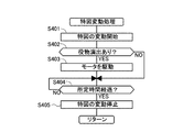
次に、特図変動処理のステップについて、詳細に説明する。図8のフローチャートに示されるように、特図表示部8aにおいて特図の変動が開始されると(S401)、主回路201は、役物(プリズム役物装置9)の演出があるか否かを判定し(S402)、演出があれば(S402でのYES)、モータ(壁部材用モータ29)を駆動させる(S403)。これにより、可動壁28が水平移動して、遊技者がプリズム部材26に表示される像を視認可能となる。所定時間が経過すると(S404でのYES)、特図の変動が停止される(S405)。なお、S404における所定時間は、例えば可動壁28を左方に最大に移動させた(即ち、プリズム窓27の全開状態)後、最初の状態に戻す(即ち、プリズム窓27の全閉状態)までの時間とすることができる。
Next, the steps of the special figure variation process will be described in detail. As shown in the flowchart of FIG. 8, when the change of the special figure is started in the special
第1実施例のプリズム役物装置9の作用について説明する。図9の(a),(b)に示されるように、遊技中に所定条件が成立すると特図の変動が開始される(「↓」は、変動中であることを示す)とともに、壁部材用モータ29が駆動して、可動壁28が水平移動される。これにより、特図表示部8aの右下部に表示される図柄からの入射光31が、プリズム部材26によって屈折し、その表面(傾斜面26aが設けられている面)に像が映し出される(第二表示態様)。図9に示される演出の場合、特図表示部8aの右下部(可動壁28の延設部33によって隠れる部分)の表示を黒塗り部41としている。このため、可動壁28が水平移動して、プリズム窓27が見え始めたとき、遊技者には、プリズム窓27の部分が真っ黒に見える。図9の(a)の状態の特図表示部8aを、図9の(c)に示す。なお、特図表示部8aの黒塗り部41が長方形状なのに、プリズム窓27の部分が半円状に見える(図9の(a)参照)のは、プリズム窓27の窓部が丸窓形状となっているからである。これにより、遊技者は、従来の遊技機にない興趣を感じるとともに、「何が現れるのだろう」という大きな期待感を抱く。
The operation of the
図10の(a),(b)に示されるように、可動壁28を水平移動させる途中で、黒塗り部41にキャラクタ42を表示させる。すると、このキャラクタ42からの入射光31が、プリズム窓27に表示されるようになる。そのときの特図表示部8aを、図10の(c)に示す。可動壁28の移動に併せてキャラクタ42を途中から表示するのではなく、最初からキャラクタ42を表示する演出としてもよい。そして、図柄変動の終了に併せて可動壁28を逆方向に水平移動させ、可動壁28が戻る過程(可動壁28が、プリズム窓27を覆い隠していく状態)で、特図表示部8aのキャラクタ42の表示を消滅させていく。これにより、特図表示部8aには、変動を終了した3つの図柄が表示され(図2の(a)の状態)、遊技者が、特図表示部8aに表示される図柄を視認するのに支障はない。
As shown in FIGS. 10A and 10B, the
次に、第2実施例のプリズム役物装置43について説明する。図11の(a),(b)に示されるように、第1実施例のプリズム役物装置9と同様に、筐体44に液晶表示装置8と第2実施例のプリズム役物装置43とが並設されている。方形板状のプリズム部材45は、プリズム窓46(本発明の副表示手段に相当)の窓部に嵌め込まれている。プリズム部材45の奥側には、平板状の壁役物47(本発明の遮断部材に相当)が配置されている。壁役物47の下端部にはラック部47aが設けられていて、壁部材用モータ48のモータ軸に取り付けられたピニオン49と噛み合っている。壁部材用モータ48を駆動させることにより、壁役物47を水平移動させ、筐体44に突出して形成された空間部44aに退避させることができる。プリズム部材45には、特図表示部8aにおける右端(3列目)の図柄が映し出されている。このため、壁役物47が筐体44の空間部44aに退避したとき、プリズム窓46には、特図表示部8aにおける3列目の図柄が表示される。
Next, the
図11の(a),(b)に示されるように、通常の遊技状態においては、壁役物47がプリズム部材45の直後方に配置されている。このため、プリズム窓46には、壁役物47の表面の模様が表示されている。所定の遊技条件が成立すると、特図表示部8aの3つの図柄が変動を開始する。所定時間の後、1列目と3列目の図柄変動が終了し、1列目と3列目に各図柄(この場合、「2」と「6」)が表示される(第一表示態様)。このとき、2列目の図柄は変動中である(「↓」で示す)。この時点で、遊技者は、特図の抽選結果が大当たりではないと感じる。
As shown in (a) and (b) of FIG. 11, in a normal gaming state, a
しかし、図12の(a),(b)に示されるように、2列目の図柄が変動中に壁役物47が水平移動を始めると、プリズム窓46に、新たな図柄が表示されるようになる(第二表示態様)。この新たな図柄は、3列目の図柄と同一なので(なぜならば、プリズム部材45には3列目の図柄が映し出されている)、壁役物47の全体が筐体44の空間部44aに退避すると、プリズム窓46には全部で4列の図柄が表示される。しかも、3列目と4列目の図柄は同一である。これは、3列目と4列目の図柄によってリーチ状態になっていることを示している。このため、図12の(c)に示されるように、変動中の2列目の図柄が停止したときに、3列目と同一の図柄が表示されれば、大当たりになる。遊技者は、いったんは大当たりになることをあきらめた後であっても、新たな有効ライン(4列目)の出現により、再び大当たりになるかもしれないという可能性を感じるため、従来の遊技機にはない新たな興趣がもたらされる。なお、2列目の図柄が停止した状態で、遊技者に大当たりであることを確実に報知するために、1列目の図柄をぼやけさせたり、半透明にさせたりしてもよい。
However, as shown in FIGS. 12A and 12B, when the
上記したように、本発明の第1及び第2の実施例のプリズム役物装置9,43では、プリズム窓27,46に何らかの図柄が表示される。即ち、第1実施例のプリズム役物装置9では、プリズム窓27に何らかの図形が徐々に表示される。このため、初めて遊技する遊技者であっても、「何か表示されたら熱いのかも」と期待感をもつことができる。また、第2実施例のプリズム役物装置43では、そのプリズム窓46に3列目の図柄と同一の図柄が表示されて自動的にリーチの状態となるため、いったんはあきらめかけた大当たりへの期待感を再度感じる。これにより、遊技者は、従来のパチンコ遊技機にない新たな興趣を感じる。また、液晶表示装置8の大きさを大きくすることなく、新たな有効ラインを出現させることができるため、安価である。
As described above, in the
第1及び第2の実施例のプリズム役物装置9,43で、可動部材(可動壁39、壁役物47)を、液晶表示装置8の前方又は後方ではなく、上下に移動させたりすることでプリズム窓27,46を出現するようにしても良い。
In the
第1実施例のプリズム役物装置9では、必要に応じて特図表示部8aの図柄の一部を隠すようにしたが、常に液晶の一部を隠しておいてもよい。また、第1実施例のプリズム役物装置9では、可動壁28の本体部によってプリズム窓27を覆い隠すとともに、可動壁28の延設部33によって筐体25の内壁面を隠している。これにより、壁部材用モータ29が1つで済むという利点がある。しかし、可動壁28の本体部と延設部33とを、別体の部材で形成してもよい。これにより、特図表示部8aの一部を隠す部材を、筐体25の上方や下方から出現させることができる。また、通常の遊技状態で、プリズム窓27に特図表示部8aの図柄が表示されないように、プリズム窓27の後方に可動部材を配置し、必要に応じて移動させたり、或いは別の部材でプリズム窓27を隠しておいて、必要に応じて上方や下方、左右方向に退避させてプリズム窓27を出現させるようにしてもよい。
In the
また、第1実施例のプリズム役物装置9では、プリズム窓27にキャラクタ42を表示する前に、黒塗り部41によって、プリズム窓27の表示を見えなくしているが、隠さなくてもよい。例えば、通常時はプリズム窓27の背後に壁役物を配置して特図表示部8aに表示されている内容をプリズム窓を通して遊技者から見えないようにしておき、所定の演出時にその壁役物を移動させることで特図表示部8aに表示された図柄をプリズム窓27を通しても見えるようにして、新たな有効ラインを出現させることもできる。
In the
次に、第3実施例のプリズム役物装置51について説明する。この実施例のパチンコ遊技機100は、所定の始動条件の成立に伴い、遊技者にとって有利となる遊技価値を付与するための内部抽選を実行する抽選手段と、その抽選手段により得られた抽選結果を遊技者に向けて複数の図柄列で表示する液晶表示装置8と、液晶表示装置8の特図表示部8aよりも遊技者側となる前方側に回転可能に配置され、特図表示部8aから発せられた光31を屈折させて前方側に伝搬させるためのプリズム部材52と、液晶表示装置8に並設されるとともに、液晶表示装置8の特図表示部8aに表示された一部の図柄列がプリズム部材52を通り、屈折像として表示可能なプリズム窓53(本発明の副表示手段に相当)と、液晶表示装置8の特図表示部8aへの図柄列の表示及びプリズム部材52を作動するモータ56を制御する表示制御回路205とを備えていて、この表示制御回路205が、液晶表示装置8の特図表示部8aに図柄列を表示させるとともに、プリズム部材52の回転によって、特図表示部8aに表示された表示内容以外の表示内容がプリズム窓53に表示されることにより液晶表示装置8の特図表示部8aのみを用いて図柄表示される第一表示態様と、特図表示部8aに表示された一部の図柄列がプリズム部材52を通り屈折像としてプリズム窓53に表示されることにより特図表示部8aとプリズム窓53とを用いて図柄表示される第二表示態様とに切換制御することを特徴としている。換言すれば、第3実施例のプリズム役物装置51には、第1及び第2の実施例のプリズム役物装置9,43が有している可動部材(可動壁28、壁役物47)を有しておらず、プリズム部材52自身が回転することによって、第二表示態様を出現させている。
Next, the
図13の(a),(b)に示されるように、プリズム役物装置51を構成するプリズム部材52は歯車形状であり、プリズム窓53の奥側に配置されている。プリズム部材52の外周部分には、3個の小歯車54が噛み合い状態で、かつ周方向に等角度で配置されている。そして、プリズム部材の一部(右端の外周縁部)が筐体55の突出部に形成された空間部55aに入り込んで奥行き方向の位置が決められている。また、筐体55には、モータ56が配置されていて、そのモータ軸には、プリズム部材52の外周面と噛み合う小歯車54のうちの1つと連結されている。モータ56を駆動すると、プリズム部材52が所定方向に回転される。また、モータ56のモータ軸に取り付けられた小歯車54以外の2つの小歯車54は、プリズム部材52の回転に伴って連れ回りする。
As shown in FIGS. 13A and 13B, the
図13の(c),(d)に示されるように、通常の遊技状態で、プリズム部材52は、その表面の溝部が高さ方向に沿って、かつ断面視においてその傾斜面52aが、図13の(d)の図面視において右下がりになるように配置されている。このため、プリズム部材52には、筐体55の内壁面が映し出されている。所定の遊技条件が成立すると、特図表示部8aの各図柄が変動を開始する。図13の(a)に示されるように、1列目と3列目の図柄変動が終了し、1列目と3列目に各図柄(この場合、「2」と「6」)が表示される(第一表示態様)。このとき、2列目の図柄は変動中である(「↓」で示す)。この時点で、遊技者は、特図の抽選結果が大当たりではないと感じる。
As shown in (c) and (d) of FIG. 13, in the normal gaming state, the
続いて、図14の(a),(b)に示されるように、プリズム部材52が回転し始める。図14の(c),(d)に示されるように、プリズム部材52が、最初の位置から右回りに90°回転すると、プリズム部材52の溝部が水平になり、プリズム窓部53には、筐体55の内部の底面壁が表示される。
Subsequently, as shown in FIGS. 14A and 14B, the
図15の(c),(d)に示されるように、更にプリズム部材51が回転すると、プリズム部材52の表面の溝部が高さ方向に沿って、かつ断面視においてその傾斜面52aが、図15の(d)の図面視において左下がりになるように配置されている。これにより、図15の(a),(b)に示されるように、特図表示部8aの3列目の図柄が徐々に、プリズム窓部53に表示されるようになる(第二表示態様)。そして、プリズム部材52が、最初の位置から180°だけ回転した状態で停止される。この状態で、プリズム窓部53には3列目と同一の図柄が表示され、遊技者は、3列目と新たな有効ラインに表示された図柄との2つの同一図柄により、リーチ状態となったことを視認できる。
As shown in FIGS. 15C and 15D, when the
上記したように、第3実施例のプリズム役物装置51では、プリズム部材52自身によって新たな有効ラインが形成される。このため、可動部材が不要となり、設計が容易になる。第1及び第2の実施例のプリズム役物装置9,43と同様に、遊技者は、いったんはあきらめかけた大当たりへの期待感を再度感じることができる。これにより、遊技者は、従来のパチンコ遊技機にない新たな興趣を感じる。また、液晶表示装置8の大きさを大きくすることなく、新たな有効ラインを出現させることができるため、安価である。
As described above, in the
上記した第3実施例のプリズム役物装置51では、プリズム部材52を回転させている。しかし、プリズム部材52を移動させたり、回転以外の姿勢変化(例えば、プリズム部材52を傾けたり、旋回させたりする)によって、第一表示態様と第二表示態様とを切り換えてもよい。
In the
本明細書では、各実施例のプリズム役物装置9,43,51をパチンコ遊技機100に取り付けた場合について説明したが、パチンコ遊技機100以外の弾球遊技機、または、スロットマシン等の回胴式遊技機であっても同様に取り付けることができる。
In the present specification, the case where the
100 パチンコ遊技機(遊技機)
201 主回路(抽選手段)
205 表示制御回路(表示制御手段)
8 液晶表示装置(主表示手段)
8a 特図表示部
26,45,52 プリズム部材
27,46,53 プリズム窓(副表示手段)
28 可動壁(遮断部材)
29,48 壁部材用モータ
31 光
47 壁役物(遮断部材)
56 モータ
100 Pachinko machines (game machines)
201 Main circuit (lottery means)
205 Display control circuit (display control means)
8 Liquid crystal display (main display means)
8a Special
28 Movable wall (blocking member)
29, 48
56 motor
Claims (6)
前記表示制御手段は、前記遮断部材の位置及び/又は姿勢を変化させて、前記遮断部材が前記伝搬経路を遮断することにより前記主表示手段のみを用いて前記特図表示部に表示された表示内容を遊技者に向けて表示させる第一表示態様と、当該第一表示態様において前記プリズム部材を通らずに視認可能である前記特図表示部に表示された表示内容の一部が前記プリズム部材を通り屈折像として前記副表示手段に表示されることにより両表示手段を用いて前記特図表示部に表示された表示内容を遊技者に向けて表示させる第二表示態様とに切換制御することを特徴とする遊技機。 In accordance with establishment of a predetermined starting condition, a lottery means for executing an internal lottery for giving a game value advantageous to the player, and a plurality of symbol strings are specially designated based on a lottery result obtained by the lottery means. a main display means for variably displaying on the display unit, the than the main display unit disposed on the front side of the player side, a prism member for propagating the main display refracts light emitted from the unit to the front side And a sub display means capable of displaying a part of the display content displayed on the special figure display section of the main display means as a refracted image through the prism member in a state of being arranged outside the main display means . A blocking member that is disposed in the middle of the light propagation path from the main display means to the player side through the prism member and the sub display means so as to be able to change position and / or posture, and can block the propagation path. And said And a display control means for controlling the operation of the display and the blocking member of said symbol rows on the display means,
The display control means changes the position and / or posture of the blocking member, and the blocking member blocks the propagation path so that the display displayed on the special figure display unit using only the main display means . A first display mode for displaying content to the player, and a part of the display content displayed on the special display unit that is visible without passing through the prism member in the first display mode is the prism member. Switching to a second display mode in which the display content displayed on the special figure display unit is displayed to the player using both display means by being displayed as a refracted image through the display . A gaming machine characterized by
前記表示制御手段は、前記遮断部材を前記副表示手段の前方に配置して前記伝搬経路を遮断することで前記第一表示態様を形成し、前記遮断部材を前記主表示手段の前方に移動させることで、前記特図表示部の前記遮断部材が位置する部位に表示された表示内容の一部が前記プリズム部材を通り屈折像として前記副表示手段に表示される前記第二表示態様に切換制御することを特徴とする請求項1に記載の遊技機。 The blocking member is provided movably between the front of the main display means and the front of the sub display means,
The display control unit forms the first display mode by disposing the blocking member in front of the sub-display unit and blocking the propagation path, and moves the blocking member to the front of the main display unit. Thus, a part of the display content displayed on the portion where the blocking member of the special figure display portion is located is controlled to switch to the second display mode in which the sub-display means is displayed as a refracted image through the prism member. The gaming machine according to claim 1, wherein:
前記表示制御手段は、前記遮断部材を前記副表示手段の後方に配置して前記伝搬経路を遮断することで前記第一表示態様を形成し、前記遮断部材を前記主表示手段及び副表示手段の前方及び後方のいずれとも重ならない方向に移動させることで、前記特図表示部に表示された表示内容の一部が前記プリズム部材を通り屈折像として前記副表示手段に表示される前記第二表示態様に切換制御することを特徴とする請求項1に記載の遊技機。 The blocking member is provided movably between a position overlapping the rear of the sub display means and a position not overlapping the front and rear of the main display means and the sub display means,
The display control unit forms the first display mode by disposing the blocking member behind the sub display unit and blocking the propagation path, and the blocking member is connected to the main display unit and the sub display unit. The second display in which a part of the display content displayed on the special figure display section is displayed on the sub display means as a refracted image through the prism member by moving in a direction that does not overlap with either the front or the rear . The gaming machine according to claim 1, wherein the game machine is controlled to be switched to a mode.
前記表示制御手段は、前記プリズム部材の位置及び/又は姿勢を変化させて、前記特図表示部に表示された表示内容以外の表示内容が前記副表示手段に表示されることにより前記主表示手段のみを用いて前記特図表示部に表示された表示内容を遊技者に向けて表示させる第一表示態様と、当該第一表示態様において前記プリズム部材を通らずに視認可能である前記特図表示部に表示された表示内容の一部が前記プリズム部材を通り屈折像として前記副表示手段に表示されることにより両表示手段を用いて前記特図表示部に表示された表示内容を遊技者に向けて表示させる第二表示態様とに切換制御することを特徴とする遊技機。 In accordance with establishment of a predetermined starting condition, a lottery means for executing an internal lottery for giving a game value advantageous to the player, and a plurality of symbol strings are specially designated based on a lottery result obtained by the lottery means. a main display means for variably displaying on the display unit, the main display means is a position change and / or the posture changeable disposed on the front side of the player side than refracts light emitted from said main display means A prism member for propagating forward, and a part of the display content displayed on the special display portion of the main display means in a state of being arranged in parallel outside the main display means refracts through the prism member. Sub-display means capable of displaying as an image, and display control means for controlling the display of the symbol row on the main display means and the operation of the prism member,
The display control means changes the position and / or orientation of the prism member, and display contents other than the display contents displayed on the special figure display section are displayed on the sub display means, thereby the main display means. A first display mode in which the display content displayed on the special map display unit is displayed to the player using only the special map display, and the special map display that is visible without passing through the prism member in the first display mode A part of the display content displayed on the part is displayed on the sub-display means as a refracted image through the prism member, so that the display content displayed on the special-figure display part can be displayed to the player using both display means . A gaming machine that is controlled to be switched to a second display mode to be displayed.
前記表示制御手段は、前記プリズム部材を前記特図表示部に表示された表示内容以外の表示内容が前記副表示手段に表示される姿勢にすることで前記第一表示態様を形成し、前記特図表示部に表示された表示内容の一部が前記プリズム部材を通り屈折像として前記副表示手段に表示される姿勢に前記プリズム部材を変化させることで前記第二表示態様に切換制御することを特徴とする請求項4に記載の遊技機。 The prism member is disposed behind the sub display means so as to be capable of changing its posture,
The display control means forms the first display form by the orientation display content other than the display contents of the prism member is displayed on the special symbol display section is displayed on the sub display unit, the Japanese Switching to the second display mode is performed by changing the prism member so that a part of the display content displayed on the figure display unit passes through the prism member and is displayed as a refracted image on the sub-display unit. The gaming machine according to claim 4, wherein the gaming machine is characterized.
前記表示制御手段は、前記第二表示態様において、前記特図表示部に表示された一部の図柄列を前記副表示手段に表示させ、両表示手段に横断的な一連の図柄列を形成して所定の向きに連続的に並んで表示させることにより、新たな有効ラインを出現させることを特徴とする請求項1ないし5のいずれか1項に記載の遊技機。 The sub display means is arranged on a side of the main display means,
In the second display mode, the display control unit causes the sub-display unit to display a part of the symbol sequence displayed on the special- symbol display unit, and forms a series of symbol sequences across both display units. 6. A gaming machine according to claim 1, wherein a new active line appears by continuously displaying the images in a predetermined direction.
Priority Applications (1)
| Application Number | Priority Date | Filing Date | Title |
|---|---|---|---|
| JP2007163565A JP5066397B2 (en) | 2007-06-21 | 2007-06-21 | Game machine |
Applications Claiming Priority (1)
| Application Number | Priority Date | Filing Date | Title |
|---|---|---|---|
| JP2007163565A JP5066397B2 (en) | 2007-06-21 | 2007-06-21 | Game machine |
Publications (2)
| Publication Number | Publication Date |
|---|---|
| JP2009000270A JP2009000270A (en) | 2009-01-08 |
| JP5066397B2 true JP5066397B2 (en) | 2012-11-07 |
Family
ID=40317328
Family Applications (1)
| Application Number | Title | Priority Date | Filing Date |
|---|---|---|---|
| JP2007163565A Expired - Fee Related JP5066397B2 (en) | 2007-06-21 | 2007-06-21 | Game machine |
Country Status (1)
| Country | Link |
|---|---|
| JP (1) | JP5066397B2 (en) |
Families Citing this family (3)
| Publication number | Priority date | Publication date | Assignee | Title |
|---|---|---|---|---|
| JP5903338B2 (en) * | 2012-06-15 | 2016-04-13 | 株式会社平和 | Game machine |
| JP5508481B2 (en) * | 2012-07-30 | 2014-05-28 | 株式会社ソフイア | Game machine |
| JP2021168798A (en) * | 2020-04-15 | 2021-10-28 | 株式会社三洋物産 | Game machine |
Family Cites Families (2)
| Publication number | Priority date | Publication date | Assignee | Title |
|---|---|---|---|---|
| JP2005160750A (en) * | 2003-12-03 | 2005-06-23 | Toyo Kasei Kk | Game machine |
| JP4261527B2 (en) * | 2005-08-29 | 2009-04-30 | 株式会社ソフィア | Game machine |
-
2007
- 2007-06-21 JP JP2007163565A patent/JP5066397B2/en not_active Expired - Fee Related
Also Published As
| Publication number | Publication date |
|---|---|
| JP2009000270A (en) | 2009-01-08 |
Similar Documents
| Publication | Publication Date | Title |
|---|---|---|
| JP2002272958A (en) | Game machine | |
| JP2005312515A (en) | Pinball machine | |
| JP4660302B2 (en) | Game machine | |
| JP2016002407A (en) | Game machine | |
| JP2007244496A (en) | Drum type display device for gaming machines | |
| JP5066397B2 (en) | Game machine | |
| JP5001709B2 (en) | Game machine | |
| JP4854446B2 (en) | Display device for gaming machine | |
| JP5084028B2 (en) | Bullet ball machine | |
| JP5213241B2 (en) | Game machine | |
| JP5551851B2 (en) | Game machine | |
| JP5690036B2 (en) | Game machine | |
| JP2008301849A (en) | Pinball game machine | |
| JP4865368B2 (en) | Game machine | |
| JP4950345B2 (en) | Method and apparatus for controlling symbol display in gaming machine | |
| JP5478001B2 (en) | Game machine | |
| JP5690035B2 (en) | Game machine | |
| JP4865369B2 (en) | Game machine | |
| JP6450088B2 (en) | Game machine | |
| JP2016214752A (en) | Game machine | |
| JP5382595B2 (en) | Game machine | |
| JP5385503B2 (en) | Game machine | |
| JP5282225B2 (en) | Game machine | |
| JP2020192248A (en) | Game machine | |
| JP2008132265A (en) | Game machine |
Legal Events
| Date | Code | Title | Description |
|---|---|---|---|
| A621 | Written request for application examination |
Free format text: JAPANESE INTERMEDIATE CODE: A621 Effective date: 20100427 |
|
| A977 | Report on retrieval |
Free format text: JAPANESE INTERMEDIATE CODE: A971007 Effective date: 20120531 |
|
| A131 | Notification of reasons for refusal |
Free format text: JAPANESE INTERMEDIATE CODE: A131 Effective date: 20120619 |
|
| A521 | Request for written amendment filed |
Free format text: JAPANESE INTERMEDIATE CODE: A523 Effective date: 20120716 |
|
| TRDD | Decision of grant or rejection written | ||
| A01 | Written decision to grant a patent or to grant a registration (utility model) |
Free format text: JAPANESE INTERMEDIATE CODE: A01 Effective date: 20120807 |
|
| A01 | Written decision to grant a patent or to grant a registration (utility model) |
Free format text: JAPANESE INTERMEDIATE CODE: A01 |
|
| A61 | First payment of annual fees (during grant procedure) |
Free format text: JAPANESE INTERMEDIATE CODE: A61 Effective date: 20120813 |
|
| R150 | Certificate of patent or registration of utility model |
Ref document number: 5066397 Country of ref document: JP Free format text: JAPANESE INTERMEDIATE CODE: R150 Free format text: JAPANESE INTERMEDIATE CODE: R150 |
|
| FPAY | Renewal fee payment (event date is renewal date of database) |
Free format text: PAYMENT UNTIL: 20150817 Year of fee payment: 3 |
|
| R250 | Receipt of annual fees |
Free format text: JAPANESE INTERMEDIATE CODE: R250 |
|
| R250 | Receipt of annual fees |
Free format text: JAPANESE INTERMEDIATE CODE: R250 |
|
| LAPS | Cancellation because of no payment of annual fees |