JP5063384B2 - Liquid coating apparatus and recording apparatus - Google Patents

Liquid coating apparatus and recording apparatus Download PDF

Info

Publication number
JP5063384B2
JP5063384B2 JP2008013066A JP2008013066A JP5063384B2 JP 5063384 B2 JP5063384 B2 JP 5063384B2 JP 2008013066 A JP2008013066 A JP 2008013066A JP 2008013066 A JP2008013066 A JP 2008013066A JP 5063384 B2 JP5063384 B2 JP 5063384B2
Authority
JP
Japan
Prior art keywords
liquid
application
coating
roller
recording
Prior art date
Legal status (The legal status is an assumption and is not a legal conclusion. Google has not performed a legal analysis and makes no representation as to the accuracy of the status listed.)
Active
Application number
JP2008013066A
Other languages
Japanese (ja)
Other versions
JP2009172840A (en
JP2009172840A5 (en
Inventor
恵世 袴田
哲洋 大橋
英明 永原
浩史 吉野
健 関野
Current Assignee (The listed assignees may be inaccurate. Google has not performed a legal analysis and makes no representation or warranty as to the accuracy of the list.)
Canon Inc
Original Assignee
Canon Inc
Priority date (The priority date is an assumption and is not a legal conclusion. Google has not performed a legal analysis and makes no representation as to the accuracy of the date listed.)
Filing date
Publication date
Application filed by Canon Inc filed Critical Canon Inc
Priority to JP2008013066A priority Critical patent/JP5063384B2/en
Priority to EP09151114.7A priority patent/EP2082810B1/en
Priority to US12/357,876 priority patent/US8146529B2/en
Priority to CN2009100011842A priority patent/CN101491980B/en
Publication of JP2009172840A publication Critical patent/JP2009172840A/en
Publication of JP2009172840A5 publication Critical patent/JP2009172840A5/ja
Application granted granted Critical
Publication of JP5063384B2 publication Critical patent/JP5063384B2/en
Active legal-status Critical Current
Anticipated expiration legal-status Critical

Links

Images

Classifications

    • BPERFORMING OPERATIONS; TRANSPORTING
    • B41PRINTING; LINING MACHINES; TYPEWRITERS; STAMPS
    • B41JTYPEWRITERS; SELECTIVE PRINTING MECHANISMS, i.e. MECHANISMS PRINTING OTHERWISE THAN FROM A FORME; CORRECTION OF TYPOGRAPHICAL ERRORS
    • B41J11/00Devices or arrangements  of selective printing mechanisms, e.g. ink-jet printers or thermal printers, for supporting or handling copy material in sheet or web form
    • B41J11/0015Devices or arrangements  of selective printing mechanisms, e.g. ink-jet printers or thermal printers, for supporting or handling copy material in sheet or web form for treating before, during or after printing or for uniform coating or laminating the copy material before or after printing
    • BPERFORMING OPERATIONS; TRANSPORTING
    • B05SPRAYING OR ATOMISING IN GENERAL; APPLYING FLUENT MATERIALS TO SURFACES, IN GENERAL
    • B05CAPPARATUS FOR APPLYING FLUENT MATERIALS TO SURFACES, IN GENERAL
    • B05C1/00Apparatus in which liquid or other fluent material is applied to the surface of the work by contact with a member carrying the liquid or other fluent material, e.g. a porous member loaded with a liquid to be applied as a coating
    • B05C1/04Apparatus in which liquid or other fluent material is applied to the surface of the work by contact with a member carrying the liquid or other fluent material, e.g. a porous member loaded with a liquid to be applied as a coating for applying liquid or other fluent material to work of indefinite length
    • B05C1/08Apparatus in which liquid or other fluent material is applied to the surface of the work by contact with a member carrying the liquid or other fluent material, e.g. a porous member loaded with a liquid to be applied as a coating for applying liquid or other fluent material to work of indefinite length using a roller or other rotating member which contacts the work along a generating line
    • B05C1/0813Apparatus in which liquid or other fluent material is applied to the surface of the work by contact with a member carrying the liquid or other fluent material, e.g. a porous member loaded with a liquid to be applied as a coating for applying liquid or other fluent material to work of indefinite length using a roller or other rotating member which contacts the work along a generating line characterised by means for supplying liquid or other fluent material to the roller
    • BPERFORMING OPERATIONS; TRANSPORTING
    • B41PRINTING; LINING MACHINES; TYPEWRITERS; STAMPS
    • B41MPRINTING, DUPLICATING, MARKING, OR COPYING PROCESSES; COLOUR PRINTING
    • B41M2205/00Printing methods or features related to printing methods; Location or type of the layers
    • B41M2205/12Preparation of material for subsequent imaging, e.g. corona treatment, simultaneous coating, pre-treatments

Description

本発明は、液体塗布装置および記録装置に関し、特にインクの凝集を早めるなどの所定の目的で記録媒体に液体と塗布する液体塗布装置および記録装置に関する。   The present invention relates to a liquid coating apparatus and a recording apparatus, and more particularly, to a liquid coating apparatus and a recording apparatus that apply a liquid to a recording medium for a predetermined purpose such as quick ink aggregation.

現在、記録装置により記録される記録媒体に、液体や液状の材料を塗布する方式として、スピンコータ、ロールコータ、バーコータ、ダイコータが知られている。これらの塗布方式は、比較的長い塗布媒体に塗布を連続的に行うことを前提としたものである。このため、例えば、比較的小さなサイズの塗布媒体が断続的に搬送されてこれらの記録媒体に塗布を行う場合には、塗布媒体ごとに、その塗布開始や終了の位置で塗料ビードが乱れるなどして均一な塗膜が得られないことがある。   Currently, spin coaters, roll coaters, bar coaters, and die coaters are known as methods for applying a liquid or a liquid material to a recording medium recorded by a recording apparatus. These coating methods are based on the premise that coating is continuously performed on a relatively long coating medium. For this reason, for example, when a relatively small size application medium is intermittently transported and applied to these recording media, the coating bead is disturbed at the application start and end positions for each application medium. A uniform coating film may not be obtained.

このような問題を解消する構成として、例えば特許文献1には、ダイコータ方式において、回転するロッドバーを用いる方法が開示されている。このロッドバーを用いる方法では、ロッドバーに対して吐出用スリットから塗布液を吐出し、ロッドバー上に塗膜を形成する。そして、形成された塗膜はロッドバーの回転に伴い塗布媒体に接触して転写される。このような方法では、ロッドバーに形成された塗膜を塗布媒体に転写、塗布しないときは、塗布液はロッドバーの回転によりヘッド内に戻り回収用スリットを介して回収される。すなわち、非塗布時でもロッドバーは回転し続け、塗布液はロッドバーに塗膜を形成した状態にある。これにより、塗布媒体が断続的に供給されそれらに断続的に塗布を行う場合でも、均一な塗膜を得ることを可能としている。   As a configuration for solving such a problem, for example, Patent Document 1 discloses a method of using a rotating rod bar in a die coater system. In the method using this rod bar, the coating liquid is discharged from the discharge slit to the rod bar to form a coating film on the rod bar. The formed coating film is transferred in contact with the coating medium as the rod bar rotates. In such a method, when the coating film formed on the rod bar is not transferred or applied to the coating medium, the coating solution returns to the head by the rotation of the rod bar and is collected through the collecting slit. That is, the rod bar continues to rotate even during non-application, and the application liquid is in a state where a coating film is formed on the rod bar. This makes it possible to obtain a uniform coating film even when the coating medium is intermittently supplied and the coating medium is intermittently applied thereto.

また、例えば特許文献2には、ローラと接するドクターブレードを用い、このブレードとローラとの間に塗布液を溜めるようにし、ローラの回転に伴ってこのローラに塗布液が付与される技術が開示されている。本技術では、ローラの回転に伴い、これと他のローラとの間を搬送される支持体に対し付与されている塗布液が転写、塗布される。さらに、特許文献3には、染料を不溶化する処理液(塗布液)を記録の前に予め塗布する機構が開示されている。本技術では、補充タンクの塗布液が回転するローラに付着することによって汲み出され、同時にその汲み出された塗布液が記録媒体に塗布されるものである。   Further, for example, Patent Document 2 discloses a technique in which a doctor blade that is in contact with a roller is used, the coating liquid is accumulated between the blade and the roller, and the coating liquid is applied to the roller as the roller rotates. Has been. In the present technology, as the roller rotates, the coating liquid applied to the support conveyed between this roller and another roller is transferred and applied. Further, Patent Document 3 discloses a mechanism for applying a treatment liquid (coating liquid) for insolubilizing a dye in advance before recording. In the present technology, the coating liquid in the replenishing tank is pumped out by adhering to a rotating roller, and at the same time, the pumped coating liquid is applied to a recording medium.

以上の特許文献1ないし3に開示された技術は、いずれも、ロッドバーまたはローラが回転しつつ、バーまたはローラの表面に塗布液が付与・供給されるところ、この付与・供給を行なう部分は、大気に開放されあるいは連通した部分である。このため、塗布液が蒸発するおそれがあり、また、装置の姿勢が変わったときに、それによって塗布液が漏れることがある。   In any of the techniques disclosed in Patent Documents 1 to 3, the application liquid is applied / supplied to the surface of the bar or roller while the rod bar or roller rotates. A part that is open to the atmosphere or communicated. For this reason, there exists a possibility that a coating liquid may evaporate, and when the attitude | position of an apparatus changes, a coating liquid may leak by it.

これに対し、インク等の液体をローラに付与・供給する部分をシールする構成が知られている。例えば、特許文献4に開示された装置は、ドクターブレードを有するインクチャンバーをローラの周面に当接させることにより、ローラとの間で液室(インク溜まり)を形成している。このような構成により、液体の蒸発および漏れを抑制することができる。   On the other hand, a configuration is known in which a portion for applying and supplying a liquid such as ink to a roller is sealed. For example, the apparatus disclosed in Patent Document 4 forms a liquid chamber (ink reservoir) with a roller by bringing an ink chamber having a doctor blade into contact with the peripheral surface of the roller. With such a configuration, evaporation and leakage of the liquid can be suppressed.

さらに、特許文献5に開示された装置は、円環状の部材をローラに当接することにより、塗布液を保持するための密閉領域を形成して、塗布液が蒸発することを防止することができる。   Furthermore, the apparatus disclosed in Patent Document 5 can prevent the coating liquid from evaporating by forming an airtight region for holding the coating liquid by contacting an annular member with the roller. .

しかしながら、特許文献4および5に開示される塗布構成では、塗布液を掻き取るドクターブレード上もしくはシールプレートに塗布液が残留することになる。間隔調整板の利用や撥水材の使用により低減することは可能であるが、塗布部材と液室とのニップ部およびその付近には塗布液は残留する。この状態で長期間にわたって装置を停止させていると、塗布部材と液室との間およびその付近に介在する塗布液の粘度が上昇し、塗布液が固着することがある。塗布液が塗布部材と液室とのニップ部で増粘・固着した場合には、塗布部材上の液室とのニップ部に相当する箇所のみ多量の塗布液が付着し、塗布部材の表面上で均一な層を形成することが困難となる。そのため、部分的に塗布液が不均一となることがある。   However, in the coating configurations disclosed in Patent Documents 4 and 5, the coating liquid remains on the doctor blade that scrapes the coating liquid or on the seal plate. Although it can be reduced by using an interval adjusting plate or using a water repellent material, the coating liquid remains in and near the nip portion between the coating member and the liquid chamber. If the apparatus is stopped for a long time in this state, the viscosity of the coating liquid interposed between and in the vicinity of the coating member and the liquid chamber increases, and the coating liquid may be fixed. When the coating liquid thickens and adheres at the nip between the coating member and the liquid chamber, a large amount of coating liquid adheres only to the portion corresponding to the nip with the liquid chamber on the coating member. Therefore, it becomes difficult to form a uniform layer. For this reason, the coating solution may be partially uneven.

これに対し、特許文献6に開示された技術では、記録動作の待機状態中に一定時間毎にローラ回転動作を行い、固着防止を行う手段が開示されている。特許文献6に開示された記録装置では、記録動作の待機中の一定時間毎にローラの空回転を行なうことにより、ローラ上に付着した増粘した塗布液を、通常の粘度に復帰させている。そして、一定時間が経過する毎に対向するローラを離間させることにより、ニップ部に塗布液が固着することを抑制している。   On the other hand, the technique disclosed in Patent Document 6 discloses a means for preventing sticking by performing a roller rotation operation at regular intervals during a standby state of a recording operation. In the recording apparatus disclosed in Patent Document 6, the thickened coating liquid adhering to the roller is returned to the normal viscosity by performing idle rotation of the roller every predetermined time while waiting for the recording operation. . Then, by separating the opposing rollers every time a certain time elapses, it is possible to prevent the coating liquid from adhering to the nip portion.

特開2001−70858号公報JP 2001-70858 A 特表2002−517341号公報JP-T-2002-517341 特開平08−72227号公報Japanese Patent Laid-Open No. 08-72227 特開平08−58069号公報JP-A-08-58069 特開2005−254229号公報JP 2005-254229 A 特開2002−96452号公報JP 2002-96452 A

しかしながら、特許文献6に開示された技術では、待機中の一定時間毎に動作を行なうため、待機時間が長ければ長いほど、消費電力が増大する。また、電源をOFFの状態で放置された場合には、内蔵電源などの機構が必要となる。さらに、一定時間が経過する毎に対向するローラを離間させるため、通常の塗布機構の他、ローラを離間させる機構が必要となり、塗布装置の機構が複雑になり、また、装置のサイズを大きくせざるを得ないことがある。   However, in the technique disclosed in Patent Document 6, since the operation is performed at fixed time intervals during standby, power consumption increases as the standby time increases. Further, when the power supply is left off, a mechanism such as a built-in power supply is required. Furthermore, since the opposing rollers are separated each time a certain time elapses, a mechanism for separating the rollers is required in addition to the normal coating mechanism, which complicates the mechanism of the coating apparatus and increases the size of the apparatus. There are times when it must be.

本発明は以上の点に鑑みてなされたものであり、新たな機構を設けることなく、塗布部材および液体供給部材の当接部で増粘・固着した塗布液を効率的に除去し、安定した塗布を行うことができる液体塗布装置および記録装置の提供を目的とする。   The present invention has been made in view of the above points, and without removing a new mechanism, the coating liquid thickened and fixed at the contact portion of the coating member and the liquid supply member is efficiently removed and stabilized. It is an object of the present invention to provide a liquid coating apparatus and a recording apparatus that can perform coating.

上記目的を達成するために本発明は、塗布面に供給された液体を記録媒体に塗布する塗布動作を行なう塗布ローラと、前記塗布面に当接して前記液体を保持する液体保持空間を形成する液体保持部材と、前記塗布動作よりも前に、前記塗布ローラの回転を伴って、前記塗布面に付着した固着液を前記液体保持空間内の前記液体に接触させることより前記固着液を溶解させる固着液除去動作を行なう制御部と、を具える液体塗布装置であって、前記制御部は、前記塗布面の部分が前記液体保持空間を通過する間に前記液体と接触する時間が、前記塗布動作時よりも前記固着液除去動作時の方が長くなるように、前記塗布ローラの回転を制御することを特徴とする。
To accomplish the above object, forms a coating roller for performing a coating operation for applying the supplied to the coating surface liquid on the recording medium, the liquid holding space for holding the liquid in contact with the coated surface Prior to the application operation with the liquid holding member, the fixing liquid is dissolved by bringing the fixing liquid attached to the application surface into contact with the liquid in the liquid holding space with the rotation of the application roller. A liquid application apparatus comprising: a control unit that performs a fixing liquid removing operation , wherein the control unit is configured so that a time during which the part of the application surface contacts the liquid while passing through the liquid holding space is The rotation of the application roller is controlled so that the time of the fixing liquid removing operation is longer than that during the operation .

以上の構成によれば、塗布動作前に塗布部材と液体保持部材との間やその付近に残留・固着した増粘した液体を再溶解することができ、塗布部材の表面上に付着する液体の不均一を抑制することができる。その結果、記録媒体にムラのない塗布動作を行うことができる。   According to the above configuration, it is possible to redissolve the thickened liquid remaining and fixed between or near the application member and the liquid holding member before the application operation, and the liquid adhering to the surface of the application member Nonuniformity can be suppressed. As a result, a coating operation without unevenness can be performed on the recording medium.

以下に図面を参照して本発明における実施形態を詳細に説明する。
(第1実施形態)
1.液体塗布部
図1は、本実施形態の液体塗布機構100の全体構成を示す斜視図である。液体塗布機構100は、塗布媒体に対し塗布液を塗布する液体塗布手段と、この液体塗布手段に塗布液を供給する液体供給手段を有している。
Embodiments of the present invention will be described below in detail with reference to the drawings.
(First embodiment)
1. Liquid Application Part FIG. 1 is a perspective view showing the overall configuration of the liquid application mechanism 100 of the present embodiment. The liquid application mechanism 100 includes a liquid application unit that applies the application liquid to the application medium, and a liquid supply unit that supplies the application liquid to the liquid application unit.

液体塗布手段は、円筒状の塗布ローラ1001、この塗布ローラ1001に対向して配置された円筒状のカウンタローラ(媒体支持部材)1002、塗布ローラ1001を駆動するローラ駆動機構1003を備えている。ローラ駆動機構1003は、ローラ駆動モータ1004と、ローラ駆動モータ1004の駆動力を塗布ローラ1001に伝達するギアトレインなどを有する動力伝達機構1005とによって構成されている。塗布ローラ1001およびカウンタローラ1002は、それぞれ、それらの両端が不図示のフレームに対して回動自在に取り付けられており、互いに平行な軸によって回動自在に支持されている。   The liquid application unit includes a cylindrical application roller 1001, a cylindrical counter roller (medium support member) 1002 disposed opposite to the application roller 1001, and a roller driving mechanism 1003 that drives the application roller 1001. The roller driving mechanism 1003 includes a roller driving motor 1004 and a power transmission mechanism 1005 having a gear train that transmits the driving force of the roller driving motor 1004 to the application roller 1001. The application roller 1001 and the counter roller 1002 are rotatably attached to both ends of the application roller 1001 and the counter roller 1002, respectively, and are rotatably supported by mutually parallel shafts.

液体供給手段は、塗布ローラ1001の周面との間で塗布液を保持する液体保持部材2001と、液体保持部材2001に液体を供給する後述する不図示の液体流路3000を備えている。液体保持部材2001は、塗布ローラ1001の長手方向のほぼ全体にわたって延在している。そして液体保持部材2001は、塗布ローラ1001の周面に対して接離動作を可能とする機構を介して不図示のフレームに移動可能に取り付けられている。   The liquid supply means includes a liquid holding member 2001 that holds the application liquid between itself and the peripheral surface of the application roller 1001, and a liquid channel 3000 (not shown) that supplies the liquid to the liquid holding member 2001. The liquid holding member 2001 extends over substantially the entire length of the application roller 1001. The liquid holding member 2001 is movably attached to a frame (not shown) via a mechanism that enables a contact / separation operation with respect to the peripheral surface of the application roller 1001.

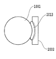
図2は、塗布ローラ1001、カウンタローラ1002および液体保持部材2001の配置の例を示す縦断側面図である。本実施形態の塗布ローラ1001の材質はゴム硬度20度のシリコン系材料であり、表面粗さはRa1.0〜2.0μm程度、直径23.169mmである。また、本実施形態のカウンタローラ1002の材質は鉄材であり、直径は12mmである。なお、シリコン系材料の一例として、液状シリコンがある。   FIG. 2 is a longitudinal side view showing an example of the arrangement of the application roller 1001, the counter roller 1002, and the liquid holding member 2001. The material of the application roller 1001 of this embodiment is a silicon-based material having a rubber hardness of 20 degrees, the surface roughness is about Ra 1.0 to 2.0 μm, and the diameter is 23.169 mm. The counter roller 1002 of this embodiment is made of iron and has a diameter of 12 mm. An example of the silicon-based material is liquid silicon.

カウンタローラ1002は、バネ部材2006により塗布ローラ1001の周面に向けて付勢されている。このような構成により、塗布ローラ1001を矢印X方向に回転させることにより、両ローラの間に塗布液が塗布される塗布媒体Pを挟持し得ると共に、塗布媒体Pを矢印Y方向に搬送している。   The counter roller 1002 is urged toward the peripheral surface of the application roller 1001 by a spring member 2006. With such a configuration, by rotating the application roller 1001 in the arrow X direction, the application medium P to which the application liquid is applied can be sandwiched between the two rollers, and the application medium P is conveyed in the arrow Y direction. Yes.

また、液体保持部材2001は、バネ部材2006の付勢力によって塗布ローラ1001の周面に対して付勢されて当接するとき、塗布ローラ1001による液体塗布領域全体に亘って延在する長尺な液体保持空間Sを形成するようになっている。この液体保持空間S内には、後述の液体供給流路3000から液体保持部材2001を介して塗布液が供給される。本実施形態の液体保持部材2001は、塗布ローラ1001が停止状態であるとき、液体保持空間Sから外方へ不用意に塗布液が漏出することを防止ないしは軽減することができるものである。また、同時に液体の蒸発を抑制することができるものである。   Further, when the liquid holding member 2001 is urged against and abuts against the peripheral surface of the application roller 1001 by the urging force of the spring member 2006, the long liquid that extends over the entire liquid application region by the application roller 1001. A holding space S is formed. In the liquid holding space S, the coating liquid is supplied through a liquid holding member 2001 from a liquid supply channel 3000 described later. The liquid holding member 2001 of the present embodiment can prevent or reduce the inadvertent leakage of the coating liquid from the liquid holding space S when the application roller 1001 is in a stopped state. At the same time, the evaporation of the liquid can be suppressed.

図3から図8は、本実施形態の液体保持部材2001の構成を示す図である。   3 to 8 are views showing the configuration of the liquid holding member 2001 of the present embodiment.

図3は、液体保持部材2001の構成を示す正面図、図4は図3A−A線にて切断した端面を示す端面図、図5は図3のB−B線にて切断した端面を示す端面図である。また、図6は、液体保持部材2001の構成を示す平面図、図7および図8は、液体塗布部材の当接部を液体塗布ローラに当接させた状態を示す左側面図および右側面図である。   3 is a front view showing the configuration of the liquid holding member 2001, FIG. 4 is an end view showing an end surface cut along line AA in FIG. 3, and FIG. 5 is an end surface cut along line BB in FIG. It is an end view. 6 is a plan view showing the configuration of the liquid holding member 2001, and FIGS. 7 and 8 are a left side view and a right side view showing a state in which the contact portion of the liquid application member is in contact with the liquid application roller. It is.

図3に示すように、液体保持部材2001は、空間形成基材2002と、空間形成基材2002の一方の面に設けられた環状の当接部材2009を備えている。空間形成基材2002には、その中央部分における長手方向に沿って、凹部2003が形成される。そして、当接部材2009は、その直線部分がこの凹部2003の上縁部に沿って固着され、また、円周部分が上縁部から底部を経て反対側の上縁部に至るように固着される。このような構成により、液体保持部材2001の当接部材2009が塗布ローラ1001に当接したとき、塗布ローラの周面形状に沿った当接が可能となり、均一な圧力の当接を実現することができる。   As shown in FIG. 3, the liquid holding member 2001 includes a space forming base material 2002 and an annular contact member 2009 provided on one surface of the space forming base material 2002. A recess 2003 is formed in the space forming substrate 2002 along the longitudinal direction of the central portion thereof. The abutting member 2009 is fixed so that the linear portion thereof is fixed along the upper edge portion of the recess 2003, and the circumferential portion is extended from the upper edge portion to the upper edge portion on the opposite side. The With such a configuration, when the abutting member 2009 of the liquid holding member 2001 abuts on the application roller 1001, it is possible to abut along the circumferential shape of the application roller, and to realize a uniform pressure abutment. Can do.

このように本実施形態の液体保持部材2001は、継ぎ目のない一体に形成された当接部材2009が、バネ部材2006の付勢力によって塗布ローラ1001の外周面に隙間なく連続した状態で当接する。その結果、液体保持空間Sは、この当接部材2009と、空間形成基材2002の一面と、塗布ローラ1001の外周面とによる実質的に閉塞した空間となり、この空間に塗布液が保持される。そして、塗布ローラ1001の回転が停止した状態では、当接部材2009と塗布ローラ1001の外周面とは液密状態を維持し、液体が外部へと漏出するのを確実に防止することができる。なおこの場合、当接部材2009の当接状態としては、当接部材2009が塗布ローラ1001の外周面に対して、直に接する状態の他、毛管力によって形成される液体の膜を介して塗布ローラ1001の外周面に当接する状態も含む。一方、塗布ローラ1001が回転するときは、塗布液は塗布ローラ1001の外周面と当接部材2009との間を摺り抜けて、塗布ローラ1001の外周面に層状に付着する。   As described above, in the liquid holding member 2001 according to the present embodiment, the abutting member 2009 formed integrally with the seam is in contact with the outer peripheral surface of the application roller 1001 without any gap by the biasing force of the spring member 2006. As a result, the liquid holding space S becomes a substantially closed space by the contact member 2009, one surface of the space forming substrate 2002, and the outer peripheral surface of the coating roller 1001, and the coating liquid is held in this space. . When the rotation of the application roller 1001 is stopped, the contact member 2009 and the outer peripheral surface of the application roller 1001 are maintained in a liquid-tight state, and it is possible to reliably prevent the liquid from leaking to the outside. In this case, as the contact state of the contact member 2009, the contact member 2009 is applied directly through the liquid film formed by the capillary force in addition to the state where the contact member 2009 is in direct contact with the outer peripheral surface of the application roller 1001. The state which contact | abuts to the outer peripheral surface of the roller 1001 is also included. On the other hand, when the application roller 1001 rotates, the application liquid slides between the outer peripheral surface of the application roller 1001 and the contact member 2009 and adheres in layers to the outer peripheral surface of the application roller 1001.

また、図6から図8に示すように、当接部材2009の長手方向における左右両側部は、緩やかに湾曲する形状をなしている。このため、塗布ローラ1001に対し、比較的強い押圧力で当接部材2009を当接させても、当接部材2009の全体が略均一に弾性変形し、局所的に大きな歪みが生じることはない。このため、当接部材2009は、隙間なく連続的に塗布ローラ1001の外周面に当接し、実質的に閉塞した空間を形成することができる。なお、液体保持部材2001は、塗布ローラ1001の略外周部に回転中心を有し、塗布ローラ中心に調芯する構造である。   Further, as shown in FIGS. 6 to 8, the left and right side portions in the longitudinal direction of the contact member 2009 have a gently curved shape. For this reason, even if the contact member 2009 is brought into contact with the application roller 1001 with a relatively strong pressing force, the entire contact member 2009 is elastically deformed substantially uniformly and no large distortion is locally generated. . For this reason, the abutting member 2009 can abut against the outer peripheral surface of the application roller 1001 continuously without a gap, and form a substantially closed space. The liquid holding member 2001 has a structure having a rotation center at a substantially outer peripheral portion of the application roller 1001 and aligning with the center of the application roller.

空間形成基材2002は、図3から図5に示すように、当接部材2009に囲繞された領域内に、それぞれ空間形成基材2002を貫通する孔を有して構成される液体供給口2004および液体回収口2005が設けられている。これらは空間形成基材2002の背面側に突設された円筒状の連結部20041および20051にそれぞれ連通している。これらの連結部20041および20051は、後述する液体供給流路3000に連結されている。なお、本実施形態では、液体供給口2004が当接部材2009に囲繞された領域の一端部(図3では左端部)近傍に形成され、液体回収口2005が同領域の他端部(図3では右端部)近傍に設けられている。液体供給口2004は、液体流路3000から供給される塗布液を液体保持空間Sに供給するためのものであり、液体回収口2005は液体保持空間S内の液体を液体流路3000へと流出させるためのものである。この液体の供給、流出を行うことにより、液体保持空間S内において、塗布液は図3に示す左端部から右端部へと流動する。   As shown in FIGS. 3 to 5, the space forming substrate 2002 has a liquid supply port 2004 configured to have holes penetrating the space forming substrate 2002 in a region surrounded by the contact member 2009. And a liquid recovery port 2005 is provided. These are in communication with cylindrical connecting portions 20009 and 20051 projecting from the back side of the space forming substrate 2002, respectively. These connecting portions 20009 and 20051 are connected to a liquid supply channel 3000 described later. In the present embodiment, the liquid supply port 2004 is formed in the vicinity of one end portion (left end portion in FIG. 3) surrounded by the contact member 2009, and the liquid recovery port 2005 is formed in the other end portion (FIG. 3). In the right end portion). The liquid supply port 2004 is for supplying the coating liquid supplied from the liquid channel 3000 to the liquid holding space S, and the liquid recovery port 2005 flows the liquid in the liquid holding space S into the liquid channel 3000. It is for making it happen. By supplying and flowing out the liquid, the coating liquid flows from the left end portion to the right end portion shown in FIG. 3 in the liquid holding space S.

2.塗布液流路および液循環部
次に、以上概略を説明した液体塗布構成の塗布液流路および液循環部の各要素についてより詳細に説明する。
2. Next, the components of the coating liquid flow path and the liquid circulation section of the liquid coating configuration outlined above will be described in more detail.

なお、本実施形態で使用する塗布液は、顔料を色材とするインクで記録した際に、顔料の凝集を早めることを目的とする液体である。塗布する液体の成分の一例としては、
硝酸カルシウム・4水和物 10%
グリセリン 42%
界面活性剤 1%
水 残量
であり、塗布液の粘度は25℃で5〜6cP(センチポアズ)である。なお、本発明の塗布液は、これに限られないことは勿論である。例えば、染料を不溶化あるいは凝集させる成分を含有する液体を塗布液として用いることも可能である。また、塗布媒体のカール(媒体が湾曲形状となる現象)を抑制する成分を含有する液体を塗布液として用いることも可能である。
Note that the coating liquid used in the present embodiment is a liquid intended to accelerate the aggregation of the pigment when recording with the ink using the pigment as the color material. As an example of the component of the liquid to apply,
Calcium nitrate tetrahydrate 10%
Glycerin 42%
Surfactant 1%
The remaining amount of water is 5 to 6 cP (centipoise) at 25 ° C. Of course, the coating solution of the present invention is not limited to this. For example, a liquid containing a component that insolubilizes or aggregates the dye may be used as the coating liquid. In addition, a liquid containing a component that suppresses curling of the coating medium (a phenomenon in which the medium has a curved shape) can be used as the coating liquid.

また、塗布する液体に水を用いる場合、本実施形態の塗布ローラとの液体保持部材の当接部分での摺動性は、表面張力を下げる成分を液体に含ませることで良好なものとなる。このような塗布する液体の成分の一例は、グリセリン及び界面活性剤が水の表面張力を下げる成分がある。   In addition, when water is used as the liquid to be applied, the slidability at the contact portion of the liquid holding member with the application roller of this embodiment is improved by including in the liquid a component that lowers the surface tension. . An example of such a liquid component to be applied is a component in which glycerin and a surfactant lower the surface tension of water.

(1)流路構成
図9は、本実施形態の塗布液供給手段の液体保持部材2001に連結される液体流路3000の概略構成を示す説明図である。液体流路3000は、空間形成基材2002の液体供給口2004と塗布液を貯蔵するバッファタンク3002とを連結する第1流路(供給流路)に含まれるチューブ3101およびチューブ3102を有する。また、液体流路3000は、空間形成基材2002の液体回収口2005とバッファタンク3002とを連結する第2流路(回収流路)に含まれるチューブ3103、3103a、3104および3105を有する。空間形成基材2002内の塗布液の有無を判定するために、第2流路の途中であるチューブ3103と3103aの間には、電気的な検知手段である液体検知センサY001が設けられている。また、バッファタンク3002には、大気連通口3004が設けられている。
(1) Channel Configuration FIG. 9 is an explanatory diagram showing a schematic configuration of the liquid channel 3000 connected to the liquid holding member 2001 of the coating liquid supply unit of the present embodiment. The liquid channel 3000 includes a tube 3101 and a tube 3102 included in a first channel (supply channel) that connects the liquid supply port 2004 of the space forming substrate 2002 and the buffer tank 3002 that stores the coating liquid. The liquid channel 3000 includes tubes 3103, 3103 a, 3104, and 3105 included in a second channel (collection channel) that connects the liquid recovery port 2005 of the space forming substrate 2002 and the buffer tank 3002. In order to determine the presence / absence of the coating liquid in the space forming substrate 2002, a liquid detection sensor Y001 as an electrical detection means is provided between the tubes 3103 and 3103a in the middle of the second flow path. . The buffer tank 3002 is provided with an air communication port 3004.

図10は、液体検知センサY001を示す概略断面図である。液体検知センサY001のジョイント部Y001b、Y001cには、チューブ3103および3103aが接続されている。また、内部には密閉された流路Y001aが形成されており、金属で形成された電極部材Y001d、Y001eが流路Y001aに突出している。電極部材Y001d、Y001eにはコネクタY005が接続されており、コネクタY005は接続手段によって不図示の検知回路に接続されている。そして、検知回路は制御部4000に接続されている。液体検知センサY001および検知回路は、電極部材Y001d、Y001eに通電することにより、流路Y001a内に塗布液の有無を判定する。   FIG. 10 is a schematic cross-sectional view showing the liquid detection sensor Y001. Tubes 3103 and 3103a are connected to the joint portions Y001b and Y001c of the liquid detection sensor Y001. Further, a sealed flow path Y001a is formed inside, and electrode members Y001d and Y001e made of metal project into the flow path Y001a. A connector Y005 is connected to the electrode members Y001d and Y001e, and the connector Y005 is connected to a detection circuit (not shown) by connection means. The detection circuit is connected to the control unit 4000. The liquid detection sensor Y001 and the detection circuit determine the presence or absence of the coating liquid in the flow path Y001a by energizing the electrode members Y001d and Y001e.

第1流路を構成するチューブ3101およびチューブ3102には三方の口を連結する第1T字流路3301が設けられている。第1T字流路3301はチューブ3101によりバッファタンク3002と連結されている。さらに三方の口を連結する合流点よりチューブ3101と連結される連結口側に連通、遮断の切換えを可能とする第1遮断弁3201が設けられている。また、第1T字流路3301はもう一方の連結口をチューブ3109と連結している。チューブ3109はバッファタンク3002に連結し、バッファタンク3002および大気連通口3004を介して大気と連通する。   The tube 3101 and the tube 3102 constituting the first flow path are provided with a first T-shaped flow path 3301 that connects the three ports. The first T-shaped channel 3301 is connected to the buffer tank 3002 by a tube 3101. Further, a first shut-off valve 3201 is provided which enables communication and shut-off switching from the junction where the three ports are connected to the connecting port connected to the tube 3101. The first T-shaped flow path 3301 connects the other connection port to the tube 3109. The tube 3109 is connected to the buffer tank 3002 and communicates with the atmosphere via the buffer tank 3002 and the atmosphere communication port 3004.

また、第一T字流路3301のチューブ3109側には、連通、遮断の切換えを可能とする第2遮断弁3202が設けられている。さらに、第1T字流路3301は残りの連結口をチューブ3102により液体供給口2004と連結している。この第1遮断弁3201と第2遮断弁3202および第1T字流路3301の構成は、2つの遮断弁の連通、遮断の組み合わせによりチューブ3102の連結先を大気とバッファタンク3002に貯蔵する塗布液の内から選択することを可能としている。   A second shut-off valve 3202 that enables switching between communication and shut-off is provided on the tube 3109 side of the first T-shaped flow path 3301. Further, the first T-shaped flow path 3301 connects the remaining connection port to the liquid supply port 2004 by the tube 3102. The configuration of the first cutoff valve 3201, the second cutoff valve 3202, and the first T-shaped flow path 3301 is a coating liquid that stores the connection destination of the tube 3102 in the atmosphere and the buffer tank 3002 by a combination of communication and cutoff of the two cutoff valves. It is possible to choose from.

さらに、第2流路には、チューブ3103、3103a、3104、3105、液体検知センサY001、本液体流路3000内で塗布液および空気をバッファタンク3002の方向へと強制的に流動させるためのポンプ3007が配置されている。ポンプ3007の、塗布液が流入する側(以下、「ポンプの上流側」ともいう。)には、チューブ3104が連結されている。一方、ポンプ3007の、塗布液が流出する側(以下、「ポンプの下流側」ともいう。)には、チューブ3105が連結されている。このチューブ3105はバッファタンク3002とポンプ3007とを連結している。   Further, in the second channel, a tube 3103, 3103a, 3104, 3105, a liquid detection sensor Y001, a pump for forcibly flowing the coating liquid and air in the direction of the buffer tank 3002 in the liquid channel 3000. 3007 is arranged. A tube 3104 is connected to a side of the pump 3007 into which the coating liquid flows (hereinafter also referred to as “upstream side of the pump”). On the other hand, a tube 3105 is connected to a side of the pump 3007 from which the coating liquid flows out (hereinafter also referred to as “downstream side of the pump”). The tube 3105 connects the buffer tank 3002 and the pump 3007.

これらの第1流路および第2流路により、バッファタンク3002と空間形成基材2002とを連結し、ポンプ3007を駆動させることでバッファタンク3002内の塗布液を空間形成基材2002に循環させながら供給することができる。   The buffer tank 3002 and the space forming base material 2002 are connected by the first flow path and the second flow path, and the pump 3007 is driven to circulate the coating liquid in the buffer tank 3002 to the space forming base material 2002. Can be supplied while.

さらに液体流路3000は、塗布液を貯蔵する交換可能な交換タンク3001と第2流路とを連結する第3流路(補給流路)と、バッファタンク3002と交換タンク3001とを連結する第4流路とを有している。なお、交換タンク3001は、バッファタンク3002よりも容積が大きいタンクである。   Furthermore, the liquid flow path 3000 is a third flow path (replenishment flow path) that connects the exchangeable exchange tank 3001 that stores the coating liquid and the second flow path, and a first flow path that connects the buffer tank 3002 and the exchange tank 3001. 4 channels. The replacement tank 3001 is a tank having a larger volume than the buffer tank 3002.

第3流路に含まれるチューブ3106は、注射針状の第1連結口3005および連結流路を構成する台座3003を介して交換タンク3001と連結している。すなわち、注射針状の第1連結口3005が、交換タンク3001の底部に設けられたゴム3501を突き抜けることによって、チューブ3106は交換タンク3001と連結される。チューブ3106のもう一方の口は前記第2T字流路3302と連結している。本実施形態では、チューブ3106が、交換タンク3001からバッファタンク3002へと塗布液を供給するための補給流路となる。   The tube 3106 included in the third flow path is connected to the replacement tank 3001 via the injection needle-like first connection port 3005 and a pedestal 3003 constituting the connection flow path. That is, the tube 3106 is connected to the replacement tank 3001 by the injection needle-like first connection port 3005 penetrating the rubber 3501 provided at the bottom of the replacement tank 3001. The other port of the tube 3106 is connected to the second T-shaped channel 3302. In the present embodiment, the tube 3106 serves as a replenishment flow path for supplying the coating liquid from the replacement tank 3001 to the buffer tank 3002.

また、第3流路および第4流路は、水蒸気バリア性が高く、柔軟性も備えた材料で構成されている。例えば、高密度ポリエチレンにより構成されている。これにより、流路内の塗布液の蒸発を最低限に抑えるとともに、本循環部を搭載する記録装置の組み立て性を向上することができる。   The third flow path and the fourth flow path are made of a material having a high water vapor barrier property and flexibility. For example, it is composed of high density polyethylene. As a result, the evaporation of the coating liquid in the flow path can be minimized, and the assemblability of the recording apparatus equipped with the circulation unit can be improved.

前記第2T字流路3302は、三方の口を連結する合流点よりチューブ3103aと連結される連結口側に、チューブ3103aと第2T字流路3302との連通、遮断の切換えを可能とする第3遮断弁3203を備えている。また、第2T字流路3302は、合流点よりチューブ3106と連結される連結口側に、チューブ3106と第2T字流路3302との連通、遮断の切換えを可能とする第4遮断弁3204を備えている。この第3遮断弁3203と第4遮断弁3204および第2T字流路3302の構成は、2つの遮断弁の連通、遮断の組み合わせによりチューブ3104との連結先を交換タンク3001と空間形成基材2002の内から選択することを可能としている。   The second T-shaped channel 3302 is configured to enable switching between communication and blocking between the tube 3103a and the second T-shaped channel 3302 on the connection port side connected to the tube 3103a from the junction that connects the three ports. A three shut-off valve 3203 is provided. In addition, the second T-shaped flow path 3302 has a fourth shut-off valve 3204 that enables switching between communication and blocking between the tube 3106 and the second T-shaped flow path 3302 on the connection port side connected to the tube 3106 from the junction. I have. The third shut-off valve 3203, the fourth shut-off valve 3204, and the second T-shaped flow path 3302 are configured by connecting the exchange tank 3001 and the space forming base material 2002 to the tube 3104 by combining the two shut-off valves. It is possible to choose from.

第4流路は、チューブ3107および3108を含んでいる。第4流路に含まれるチューブ3108は、注射針状の第2連結口3006および連結流路を構成する台座3003を介して交換タンク3001と連結する。すなわち、注射針状の第2の連結口3006が、交換タンク3001の底部に設けられたゴム3502を突き抜けることによって、チューブ3108は交換タンク3001と連結される。交換タンク3001は、チューブ3107とチューブ3108との連通、遮断の切換えを可能とする第5遮断弁3205を介してバッファタンク3002と連通している。   The fourth flow path includes tubes 3107 and 3108. The tube 3108 included in the fourth flow path is connected to the replacement tank 3001 via the injection needle-like second connection port 3006 and a pedestal 3003 constituting the connection flow path. That is, the tube 3108 is connected to the replacement tank 3001 by the injection needle-like second connection port 3006 penetrating the rubber 3502 provided at the bottom of the replacement tank 3001. The exchange tank 3001 communicates with the buffer tank 3002 via a fifth shutoff valve 3205 that enables communication between the tube 3107 and the tube 3108 and switching of the shutoff.

また、交換タンク3001内には、大気連通パイプ3001aが設けられている。大気連通パイプ3001aは、下端が第2の連結口3006に接続され、上端は交換タンク3001内の空気層Aに突出している。このような構成により、第5遮断弁3205を開放すると、交換タンク3001内の塗布液Lを循環経路に流出させることなく、交換タンク3001の内圧を外気と均衡にすることができる。この第4流路を設けることによって、交換タンク3001に大気連通口を設ける必要が無くなる。また、第4流路を設けることによって、交換タンク3001からバッファタンク3002へと塗布液を補給する際に、循環補給を行うことができる。バッファタンク3002への塗布液の補給時に、バッファタンク3002内に塗布液が残っている場合、この残った塗布液は、蒸発等により増粘することがある。しかしながら、本実施形態によれば、バッファタンク3002に供給された塗布液と残った塗布液とが相溶し、さらに相溶した塗布液が循環補給により交換タンク3001へと送られる。よって、バッファタンク内の蒸発による塗布液への影響をより軽減することができる。   In addition, an atmospheric communication pipe 3001a is provided in the exchange tank 3001. The atmospheric communication pipe 3001 a has a lower end connected to the second connection port 3006 and an upper end protruding into the air layer A in the exchange tank 3001. With this configuration, when the fifth shut-off valve 3205 is opened, the internal pressure of the replacement tank 3001 can be balanced with the outside air without causing the coating liquid L in the replacement tank 3001 to flow out to the circulation path. By providing this fourth flow path, it is not necessary to provide an atmosphere communication port in the exchange tank 3001. In addition, by providing the fourth flow path, circulation replenishment can be performed when the application liquid is replenished from the replacement tank 3001 to the buffer tank 3002. If the application liquid remains in the buffer tank 3002 when the application liquid is supplied to the buffer tank 3002, the remaining application liquid may thicken due to evaporation or the like. However, according to this embodiment, the coating liquid supplied to the buffer tank 3002 and the remaining coating liquid are compatible, and the compatible coating liquid is sent to the replacement tank 3001 by circulation replenishment. Therefore, the influence on the coating liquid due to evaporation in the buffer tank can be further reduced.

また、本実施形態では、交換タンク3001への連結口を注射針状とし、交換タンク3001の底部をゴムにてシールしているので、交換タンクの未装着時における、交換タンク内の塗布液の蒸発を抑制できる。   In this embodiment, the connection port to the replacement tank 3001 is shaped like an injection needle, and the bottom of the replacement tank 3001 is sealed with rubber, so that the coating liquid in the replacement tank when the replacement tank is not attached is used. Evaporation can be suppressed.

なお、各遮断弁の切換えは、制御部からの制御信号によって行われ、塗布液の充填、供給、回収などが行われる。具体的な動作の詳細は後述する。   Note that switching of each shut-off valve is performed by a control signal from the control unit, and filling, supply, recovery, and the like of the coating liquid are performed. Details of the specific operation will be described later.

本実施形態では、ポンプ3007の上流側で、回収流路と補給流路とを合流させ、かつポンプ3007へと繋がる流路と、回収流路と補給流路との連結の切換を行っている。この切換時によって、回収流路とポンプ3007とが連結された場合は、補給流路とポンプ3007とは連結されていない。よって、このとき、ポンプ3007により、第1流路、液体保持空間Sおよび第2流路内で、塗布液の循環、液体保持空間Sに対する塗布液の供給、回収を行うことができる。一方、切換により、補給流路とポンプ3007とが連結された場合は、回収流路とポンプ3007とは連結されていない。よって、このとき、第3流路を介して、交換タンク3001からバッファタンク3002へと塗布液を補給することができる。   In the present embodiment, on the upstream side of the pump 3007, the recovery channel and the supply channel are merged, and the connection between the channel connected to the pump 3007 and the recovery channel and the supply channel is switched. . When the recovery flow path and the pump 3007 are connected by this switching, the replenishment flow path and the pump 3007 are not connected. Therefore, at this time, the pump 3007 can circulate the coating liquid, and supply and collect the coating liquid to the liquid holding space S in the first flow path, the liquid holding space S, and the second flow path. On the other hand, when the supply channel and the pump 3007 are connected by switching, the recovery channel and the pump 3007 are not connected. Therefore, at this time, the coating liquid can be supplied from the replacement tank 3001 to the buffer tank 3002 via the third flow path.

このように、本実施形態では、ポンプ3007の上流側で、回収流路と補給流路との合流およびこれら流路の切換を行い、ポンプ3007と連通しない方の流路をポンプ3007に対して遮断している。したがって、バッファタンク3002と交換タンク3001とを有する流路の制御を、1つのポンプにより行うことが可能となる。すなわち、同一装置内でバッファタンクと交換タンクとを同時に配置しても、ポンプの数を増やす必要が無い。これにより、ポンプの増加に伴う流路や制御部を増やす必要が無いため、ポンプを含めて部品数の増加を抑制でき、装置の大型化を招かず、またコストダウンにも繋がる。   As described above, in the present embodiment, on the upstream side of the pump 3007, the recovery flow path and the replenishment flow path are merged and the flow paths are switched, and the flow path not communicating with the pump 3007 is connected to the pump 3007. It is shut off. Therefore, the flow path having the buffer tank 3002 and the exchange tank 3001 can be controlled by one pump. That is, it is not necessary to increase the number of pumps even if the buffer tank and the exchange tank are simultaneously arranged in the same apparatus. As a result, there is no need to increase the number of flow paths and control units accompanying the increase in the number of pumps, so that an increase in the number of parts including the pump can be suppressed, the apparatus is not increased in size, and the cost is reduced.

また、本実施形態では、バッファタンク3002と交換タンク3001とを同一の装置内に設けても、ポンプの数は1つで済む。よって、水頭差制御などの目的でバッファタンクを設ける場合であっても、液体塗布に必要な部材を、同一の液体塗布装置内に収めることができる。   In this embodiment, even if the buffer tank 3002 and the exchange tank 3001 are provided in the same apparatus, only one pump is required. Therefore, even when a buffer tank is provided for the purpose of controlling the head differential, a member necessary for liquid application can be accommodated in the same liquid application apparatus.

さらに、本実施形態において、塗布動作中では、塗布液は第1流路、液体保持空間S、第2流路、バッファタンク3002を循環しているので、塗布動作時に混入したゴミや紙粉等による注射針状の連結口へのゴミ詰まりを回避することができる。   Further, in the present embodiment, during the application operation, the application liquid circulates through the first flow path, the liquid holding space S, the second flow path, and the buffer tank 3002, so that dust, paper powder, and the like mixed during the application operation are used. It is possible to avoid clogging of dust in the injection needle-like connection port.

液体保持空間Sから塗布ローラ1001への塗布液の塗布量の安定化を実現するためには、貯蔵タンク内の塗布液を消費しても、貯蔵タンク内の塗布液の液面と液体保持空間Sとの水頭差の変動を抑えることが望ましい。このような貯蔵タンク内の塗布液の消費に伴う水頭差の変動を抑えるためには、貯蔵タンクの高さを小さくすれば良い。しかしながら、貯蔵タンクに貯蔵できる塗布液の量は多ければ多いほど好ましい、ということを考慮すると、高さの小さい貯蔵タンクにおいてより多くの塗布液を貯蔵しようとすると、その底面積を大きくしなければならない。これでは装置の大型化に繋がってしまう。そこで、本実施形態では、役割が異なる、交換タンク3001とバッファタンク3002を用いている。すなわち、交換タンク3001よりも小さい容積であって、少なくとも交換タンク3001よりも低い高さであるバッファタンク3002を用いて、液体保持空間Sに対して塗布液の循環、充填、回収を行う。また、同一の装置内に、バッファタンク3002よりも大きな容積を有する交換タンク3001により、多量の塗布液を貯蔵する。バッファタンク3002の容積は交換タンク3001に比べて小さいので、塗布液を使い切るまでの時間も早くなるが、随時、交換タンク3001からバッファタンク3002へと塗布液の補給を行う。このように、装置内に貯蔵できる塗布液の量を多量にしつつ、液体保持空間Sに対する塗布液の、充填、回収、循環に関わる貯蔵タンク(バッファタンク)の高さを小さくすることができる。よって、バッファタンク3002内の塗布液を消費しても、バッファタンク3002内の塗布液の液面と、液体保持空間Sとの間の水頭差の変動を抑えることができる。その結果、塗布ローラ1001による塗布液の塗布量を安定化することが可能となる。   In order to stabilize the application amount of the application liquid from the liquid holding space S to the application roller 1001, even if the application liquid in the storage tank is consumed, the liquid level of the application liquid in the storage tank and the liquid holding space It is desirable to suppress the fluctuation of the water head difference from S. In order to suppress the fluctuation of the water head difference due to the consumption of the coating liquid in the storage tank, the height of the storage tank may be reduced. However, in view of the fact that the larger the amount of coating liquid that can be stored in the storage tank, the more preferable it is to store more coating liquid in a storage tank with a small height, the bottom area must be increased. Don't be. This leads to an increase in the size of the apparatus. Therefore, in this embodiment, an exchange tank 3001 and a buffer tank 3002 having different roles are used. That is, the coating liquid is circulated, filled, and collected in the liquid holding space S by using the buffer tank 3002 that has a smaller volume than the replacement tank 3001 and at least a height lower than the replacement tank 3001. Further, a large amount of coating liquid is stored in the same apparatus by an exchange tank 3001 having a volume larger than that of the buffer tank 3002. Since the volume of the buffer tank 3002 is smaller than that of the replacement tank 3001, the time until the coating liquid is used up is also shortened. However, the coating liquid is replenished from the replacement tank 3001 to the buffer tank 3002 as needed. As described above, the height of the storage tank (buffer tank) related to filling, recovery, and circulation of the coating liquid with respect to the liquid holding space S can be reduced while increasing the amount of the coating liquid that can be stored in the apparatus. Therefore, even if the application liquid in the buffer tank 3002 is consumed, fluctuations in the water head difference between the liquid level of the application liquid in the buffer tank 3002 and the liquid holding space S can be suppressed. As a result, it is possible to stabilize the application amount of the application liquid by the application roller 1001.

また、水頭差の変動を抑えることにより、塗布ローラ1001および当接部材2009の磨耗を低減することができる。本実施形態では、ポンプ3007を、バッファタンク3002への回収側に設けているので、塗布液の循環の際には、液体回収口2005での圧力は液体供給口2004での圧力よりも相対的に低くなり、減圧方式の循環が達成される。よって、液体保持空間S内には負圧が発生することになるが、この負圧は、水頭差が大きくなるに従って大きくなる。本実施形態では、バネ部材2006のバネ付勢によって当接部材2009を塗布ローラ1001に押圧しているが、水頭差の増大による負圧の増大により、押圧力も増大してしまう。この押圧力の増大によって、塗布ローラ1001と当接部材2009との当接部の磨耗も増大してしまう。しかしながら、本実施形態では、水頭差の変動を抑えることができるので、磨耗を低減させることができ、塗布ローラ1001および当接部材2009の耐久性を向上させることが可能となる。   In addition, wear of the application roller 1001 and the contact member 2009 can be reduced by suppressing fluctuations in the water head difference. In the present embodiment, since the pump 3007 is provided on the recovery side to the buffer tank 3002, the pressure at the liquid recovery port 2005 is relative to the pressure at the liquid supply port 2004 when the coating liquid is circulated. The circulation of the decompression system is achieved. Therefore, a negative pressure is generated in the liquid holding space S, and this negative pressure increases as the water head difference increases. In the present embodiment, the contact member 2009 is pressed against the application roller 1001 by the spring bias of the spring member 2006, but the pressing force also increases due to an increase in negative pressure due to an increase in water head difference. Due to the increase in the pressing force, the wear of the contact portion between the application roller 1001 and the contact member 2009 also increases. However, in this embodiment, since the fluctuation of the water head difference can be suppressed, wear can be reduced, and the durability of the application roller 1001 and the contact member 2009 can be improved.

(2)制御系
図11は、本実施形態の液体塗布装置における制御系の概略構成を示すブロック図である。図11において、制御部4000は液体塗布装置全体を制御する制御手段である。この制御部4000は、種々の演算、制御、判別などの処理動作を実行するCPU4001を有する。また、制御部4000は、図12にて後述するCPU4001によって実行される処理などの制御プログラムなどを格納するROM4002と、CPU4001の処理動作中のデータや入力データなどを一時的に格納するRAM4003などを有している。
(2) Control System FIG. 11 is a block diagram showing a schematic configuration of a control system in the liquid coating apparatus of this embodiment. In FIG. 11, a control unit 4000 is a control unit that controls the entire liquid application apparatus. The control unit 4000 includes a CPU 4001 that executes processing operations such as various calculations, control, and determination. In addition, the control unit 4000 includes a ROM 4002 that stores a control program such as a process executed by the CPU 4001 described later in FIG. 12, a RAM 4003 that temporarily stores data during operation of the CPU 4001, input data, and the like. Have.

この制御部4000には、所定の指令あるいはデータなどを入力するキーボードあるいは各種スイッチなどを含む入力操作部4004、液体塗布装置の入力・設定状態などをはじめとする種々の表示を行う表示部4005が接続されている。また、制御部4000には、塗布媒体の位置や各部の動作状態などを検出するセンサなどを含む検出部4006が接続されている。前述の液体検知センサY001は、検出部4006の一部である。さらに、制御部4000には、ローラ駆動モータ1004、ポンプ駆動モータ4009、第1〜第5切換弁3201〜3205が、それぞれ駆動回路4007,4008,4011を介して接続されている。   The control unit 4000 includes an input operation unit 4004 including a keyboard or various switches for inputting predetermined commands or data, and a display unit 4005 for performing various displays including the input / setting state of the liquid coating apparatus. It is connected. The control unit 4000 is connected to a detection unit 4006 including a sensor that detects the position of the application medium, the operation state of each unit, and the like. The liquid detection sensor Y001 described above is a part of the detection unit 4006. Further, a roller drive motor 1004, a pump drive motor 4009, and first to fifth switching valves 3201 to 3205 are connected to the control unit 4000 via drive circuits 4007, 4008, and 4011, respectively.

(3)液体塗布動作シーケンス
図12は、本実施形態の液体塗布装置における液体塗布の処理手順を示すフローチャートである。液体塗布装置に電源が投入されると、制御部4000は、図12に示すフローチャートに従って塗布動作シーケンスを実行する。以下、このフローチャートを参照して、液体塗布にかかる各工程を説明する。
(3) Liquid Application Operation Sequence FIG. 12 is a flowchart showing a liquid application processing procedure in the liquid application apparatus of this embodiment. When the power is supplied to the liquid coating apparatus, the control unit 4000 executes a coating operation sequence according to the flowchart shown in FIG. Hereinafter, with reference to this flowchart, each process concerning liquid application will be described.

なお各遮断弁の開閉組み合わせを、以下の表1に示す「放置」、「補給」、「循環」、「回収」の4つの組み合わせとする。制御部4000は、装置の状態に適切な組み合わせを選択し、選択された組み合わせに対応する動作を行うように各遮断弁へと制御信号を送信する。   The open / close combinations of the shut-off valves are the four combinations of “Left”, “Replenishment”, “Circulation”, and “Recovery” shown in Table 1 below. The control unit 4000 selects a combination appropriate for the state of the apparatus, and transmits a control signal to each cutoff valve so as to perform an operation corresponding to the selected combination.

Figure 0005063384
Figure 0005063384

ここで「放置」とは、非動作時であって、液体保持空間Sから塗布液を回収した状態の各遮断弁の状態である。「補給」とは、交換タンク3001からバッファタンク3002へと塗布液を補給する際の各遮断弁の状態である。「循環」とは、バッファタンク3002、第1流路、液体保持空間S、第2流路内において塗布液を循環させる際の各遮断弁の状態である。「回収」とは、液体保持空間Sからバッファタンク3002へと塗布液を回収する際の各遮断弁の状態である。   Here, “leaving” is a state of each shut-off valve in a state in which the coating liquid is recovered from the liquid holding space S when not in operation. “Replenishment” is the state of each shut-off valve when the coating liquid is replenished from the replacement tank 3001 to the buffer tank 3002. “Circulation” is the state of each shut-off valve when the coating liquid is circulated in the buffer tank 3002, the first flow path, the liquid holding space S, and the second flow path. “Recovery” is the state of each shutoff valve when recovering the coating liquid from the liquid holding space S to the buffer tank 3002.

また、「放置」の状態として、第2遮断弁を「閉」状態にすることも可能である。この場合は、液体保持空間Sとバッファタンク3002が完全に遮断されることになるので、非動作時の如何なる状況においても、バッファタンク3002内の塗布液が液体保持空間Sに侵入していくことはなくなる。   In addition, the second shut-off valve can be set to the “closed” state as the “leaving” state. In this case, since the liquid holding space S and the buffer tank 3002 are completely cut off, the coating liquid in the buffer tank 3002 enters the liquid holding space S in any situation during non-operation. Will disappear.

(3−1)充填工程
図13は、図12のステップS1における保持空間Sに対する塗布液の充填工程の動作の詳細を示すフローチャートである。この充填工程では、塗布動作が開始されると(ステップS10)、各遮断弁を切り替えることにより、「循環」の開閉組み合わせにする(ステップS11)。この開閉組み合わせにすると、液体保持空間Sに対して第1流路および第2流路によってバッファタンク3002が連通する。
(3-1) Filling Process FIG. 13 is a flowchart showing details of the operation of the filling process of the coating liquid into the holding space S in step S1 of FIG. In this filling process, when the application operation is started (step S10), the switching operation of each shut-off valve is performed to make an open / close combination of “circulation” (step S11). With this open / close combination, the buffer tank 3002 communicates with the liquid holding space S through the first flow path and the second flow path.

その後、液体検知センサY001で液の有無を監視しながら、ポンプ3007を通常の速度で駆動する(ステップS12)。ポンプ3007の駆動により、第1流路、液体保持空間S、チューブ3103、液体検知センサY001の順に塗布液が供給される。そして、液体検知センサY001の流路Y001aが塗布液で満たされると、液体検知センサY001により液体が有る状態を検知されたか否かを判断する(ステップS13)。液体検知センサY001により液体が検知されると、ポンプ3007の駆動が停止される。この場合には、塗布ローラ1001に対し塗布液が供給された状態となっているため、塗布媒体への塗布が可能となり(ステップS16)、塗布動作を行なう(ステップS17)。   Thereafter, the pump 3007 is driven at a normal speed while monitoring the presence or absence of the liquid with the liquid detection sensor Y001 (step S12). By driving the pump 3007, the coating liquid is supplied in the order of the first flow path, the liquid holding space S, the tube 3103, and the liquid detection sensor Y001. Then, when the flow path Y001a of the liquid detection sensor Y001 is filled with the coating liquid, it is determined whether or not the liquid detection sensor Y001 has detected a state in which liquid is present (step S13). When the liquid is detected by the liquid detection sensor Y001, the driving of the pump 3007 is stopped. In this case, since the application liquid is supplied to the application roller 1001, application to the application medium is possible (step S16), and an application operation is performed (step S17).

一方、液体検知センサY001により液体が有る状態を検知しない場合には、塗布ローラを駆動する(ステップS14)。すなわち、液体検知センサY001に液が充填されるために十分な量ポンプ3007を駆動しても、液体検知センサY001が液有を検知できない場合がある。その原因として、例えば、ポンプ或いは循環経路の不良がある。また、他の原因として、塗布液がポンプ内で増粘して粘性抵抗が高くなり、通常のポンプ速度ではポンプが正常に機能しないことがある。さらに、塗布液が循環経路内で増粘し、流動速度が遅くなっていることがある。また、液体検知センサY001の流路Y001aに塗布液があっても、液有と検知されないことがある。   On the other hand, when the liquid detection sensor Y001 does not detect the presence of liquid, the application roller is driven (step S14). That is, there are cases where the liquid detection sensor Y001 cannot detect the presence of liquid even if the pump 3007 that is sufficient to fill the liquid detection sensor Y001 with the liquid is driven. The cause is, for example, a pump or a defective circulation path. As another cause, the coating liquid thickens in the pump and the viscosity resistance increases, and the pump may not function normally at a normal pump speed. Furthermore, the coating liquid may thicken in the circulation path, resulting in a slow flow rate. Even if there is a coating liquid in the flow path Y001a of the liquid detection sensor Y001, it may not be detected that there is a liquid.

このように、ポンプ3007を十分な量駆動しても液体検知センサY00により液体が有る状態が検知されなかった場合(ステップS13)、ローラ駆動モータ1004を駆動して塗布ローラ1001を回転させる(ステップS14)。このときの駆動負荷を、ローラ駆動モータ1004の駆動電流或いはPWMのデューティなどにより検知する(ステップS15)。負荷が閾値未満の場合には、液体保持空間S内に塗布液が存在していると判断し(ステップS16)、その後の塗布動作を行う(ステップS17)。   As described above, even when the pump 3007 is driven by a sufficient amount, if the liquid detection sensor Y00 does not detect the presence of liquid (step S13), the roller driving motor 1004 is driven to rotate the application roller 1001 (step S13). S14). The driving load at this time is detected by the driving current of the roller driving motor 1004 or the duty of PWM (step S15). When the load is less than the threshold value, it is determined that the coating liquid is present in the liquid holding space S (step S16), and the subsequent coating operation is performed (step S17).

負荷が閾値以上の場合には(ステップS15)、液体保持空間S内に塗布液が存在していないと判断し、塗布液を充填させるためにポンプ3007を低速で再度駆動する(ステップS19)。その結果、液体検知センサY001が塗布液有を検知した場合には、液体保持空間S内に塗布液が存在していると判断し(ステップS13、S16)、その後の塗布動作に進む(ステップS17)。   If the load is equal to or greater than the threshold (step S15), it is determined that no coating liquid exists in the liquid holding space S, and the pump 3007 is driven again at a low speed to fill the coating liquid (step S19). As a result, when the liquid detection sensor Y001 detects the presence of the coating liquid, it is determined that the coating liquid is present in the liquid holding space S (steps S13 and S16), and the subsequent coating operation is performed (step S17). ).

ポンプ3007の再駆動を行っても液体検知センサY001により液体が有る状態が検知されなかった場合は、塗布ローラ1001を再度駆動し(ステップS14)、ローラ駆動モータ1004の駆動負荷を検出する(ステップS15)。駆動負荷が閾値未満であれば、液体保持空間S内に塗布液が存在していると判断し(ステップS16)、その後の塗布動作を行う(ステップS17)。一方、駆動負荷が再度閾値以上だった場合は、ポンプ3007或いは液体流路3000に何らかの異常が発生していると判断し、ステップS18を経て循環系エラーとなる(ステップS20)。   If the liquid detection sensor Y001 does not detect the presence of liquid even after the pump 3007 is re-driven, the application roller 1001 is driven again (step S14), and the driving load of the roller drive motor 1004 is detected (step S14). S15). If the driving load is less than the threshold value, it is determined that the coating liquid is present in the liquid holding space S (step S16), and the subsequent coating operation is performed (step S17). On the other hand, if the drive load is equal to or greater than the threshold value again, it is determined that some abnormality has occurred in the pump 3007 or the liquid flow path 3000, and a circulatory system error is generated through step S18 (step S20).

なお、本実施形態では、ステップS19におけるポンプ3007の再駆動の際、ポンプの駆動速度を変更している。しかしながら、本発明のポンプの再駆動は、ステップS12におけるポンプ3007の駆動と同じ速度であってもよい。例えば、駆動速度を早くすると、ポンプでより大きい負圧を発生することが出来、塗布液が増念して流動速度が遅くなっている場合の流動速度を早くすることが出来る。また、駆動速度を遅くすると、ポンプ内で塗布液が増粘した場合でもポンプをほぼ正常に機能させることが出来る。   In the present embodiment, the pump driving speed is changed when the pump 3007 is re-driven in step S19. However, the re-driving of the pump of the present invention may be the same speed as the driving of the pump 3007 in step S12. For example, if the driving speed is increased, a larger negative pressure can be generated by the pump, and the flow speed can be increased when the coating liquid is increased and the flow speed is reduced. Moreover, if the drive speed is slowed down, the pump can function almost normally even when the coating liquid thickens in the pump.

また、ステップS14におけるローラ駆動モータ1004の駆動は、記録用紙の搬送動作を行うための予備動作を利用することも出来る。予備動作とは、例えば後述する固着液除去動作がある。このようにすると、液体保持空間S内の塗布液の有無の検知のための新しい動作を追加する必要がなくなり、動作時間の短縮につながる。   In addition, the roller drive motor 1004 can be driven in step S14 using a preliminary operation for carrying the recording paper. The preliminary operation includes, for example, a fixing liquid removing operation described later. In this way, it is not necessary to add a new operation for detecting the presence or absence of the coating liquid in the liquid holding space S, leading to a reduction in operation time.

(3−2)補給工程
図12のステップS1で、液体保持部材内の液面の高さを検知するための液面管理手段としてのセンサ等により、バッファタンク3002内の塗布液の充填が不十分であると判断する場合は、各遮断弁を「補給」の開閉組み合わせにする。その後、ポンプ3007を一定時間駆動する。この開閉組み合わせにすると、交換タンク3001に対して第3流路および第4流路によってバッファタンク3002が連通する。これにより、バッファタンク3002に塗布液が補給されていく。
(3-2) Replenishment Step In step S1 of FIG. 12, the filling of the coating liquid in the buffer tank 3002 is not performed by a sensor or the like as a liquid level management means for detecting the height of the liquid level in the liquid holding member. When it is determined that the value is sufficient, each shut-off valve is set to a “replenishment” open / close combination. Thereafter, the pump 3007 is driven for a certain time. With this open / close combination, the buffer tank 3002 communicates with the replacement tank 3001 through the third flow path and the fourth flow path. As a result, the coating liquid is supplied to the buffer tank 3002.

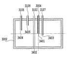
図14、図15および図16は、本実施形態のバッファタンク3002の構成を示す概略図である。本実施形態におけるバッファタンクの内部の空間は説明の便宜を考慮して直方体とする。   14, FIG. 15 and FIG. 16 are schematic views showing the configuration of the buffer tank 3002 of the present embodiment. The space inside the buffer tank in the present embodiment is a rectangular parallelepiped for convenience of explanation.

図14において、バッファタンク3002の内部と供給流路3101に連結する流路とは開口部3402で連通している。バッファタンク3002の内部と回収流路3105に連結する流路とは開口部3404で連通している。バッファタンク3002の内部とチューブ3109に連結する流路とは開口部3405で連通している。開口部3403は交換タンク3001と連通している第4流路であるチューブ3107と連通している。開口部3401は大気連通口3004と連通している。   In FIG. 14, the inside of the buffer tank 3002 and the flow path connected to the supply flow path 3101 communicate with each other through an opening 3402. The inside of the buffer tank 3002 and the flow path connected to the recovery flow path 3105 communicate with each other through an opening 3404. The inside of the buffer tank 3002 and the flow path connected to the tube 3109 communicate with each other through an opening 3405. The opening 3403 communicates with a tube 3107 that is a fourth flow path communicating with the replacement tank 3001. The opening 3401 is in communication with the atmosphere communication port 3004.

開口部3404の垂直方向における位置に制約は無い。本実施形態の開口部3404の垂直方向における位置は、説明の便宜上図14に示す位置とする。開口部3402はバッファタンク3002内の塗布液をなるべく有効に使用できる様にバッファタンク3002の底面に近い位置にする。開口部3405は回収動作の際に大気と連通する必要があり、バッファタンク3002内部を経由して大気連通口3004と連通していなければならない。よって、開口部3405の垂直方向における位置はバッファタンク3002の天井に近い位置にする。但し補給動作の際には、開口部3402および開口部3405に連通する流路は各々の弁により遮断されている為、開口部が無い構造と等価である。開口部3401はバッファタンク3002の内部空間の中心になるべく近い位置とする。ここで、バッファタンク3002の内部空間の形状を均一な物質で形成した際の重心をバッファタンク3002の内部空間の中心を定義する。開口部3403の垂直方向における位置は前記の開口部3401の位置よりも低く位置にする。   There is no restriction on the position of the opening 3404 in the vertical direction. The position of the opening 3404 in the present embodiment in the vertical direction is the position shown in FIG. 14 for convenience of explanation. The opening 3402 is positioned close to the bottom surface of the buffer tank 3002 so that the coating liquid in the buffer tank 3002 can be used as effectively as possible. The opening 3405 needs to communicate with the atmosphere during the recovery operation, and must communicate with the atmosphere communication port 3004 via the buffer tank 3002. Therefore, the position of the opening 3405 in the vertical direction is set close to the ceiling of the buffer tank 3002. However, in the replenishment operation, the flow path communicating with the opening 3402 and the opening 3405 is blocked by the respective valves, which is equivalent to a structure having no opening. The opening 3401 is positioned as close as possible to the center of the internal space of the buffer tank 3002. Here, the center of the internal space of the buffer tank 3002 is defined as the center of gravity when the internal space of the buffer tank 3002 is formed of a uniform material. The position of the opening 3403 in the vertical direction is set lower than the position of the opening 3401.

図15および図16に示す様に、この充填は、バッファタンク3002の内部に位置する第4流路の端部である開口部3403の水位まで行われる。この第4流路の端部3403の水位まで塗布液が充填されると交換タンクとバッファタンク3002間での循環の流れになり、バッファタンク3002内の水位は変化しない。この第4流路の端部3403がバッファタンクの大気連通口である開口部3401の位置よりも重力方向に低い位置に配置することで、大気連通口から塗布液が流出することはない。本構成によれば補給工程においてポンプ3007の駆動時間に関わらずバッファタンク3002からの液漏れは発生しない。   As shown in FIGS. 15 and 16, this filling is performed up to the water level of the opening 3403 that is the end of the fourth flow path located inside the buffer tank 3002. When the coating liquid is filled up to the water level at the end 3403 of the fourth flow path, the flow of circulation occurs between the replacement tank and the buffer tank 3002, and the water level in the buffer tank 3002 does not change. By disposing the end 3403 of the fourth flow path at a position lower in the gravitational direction than the position of the opening 3401 that is the atmosphere communication port of the buffer tank, the coating liquid does not flow out from the atmosphere communication port. According to this configuration, liquid leakage from the buffer tank 3002 does not occur in the replenishment process regardless of the driving time of the pump 3007.

なお、別の構成として、バッファタンク3002内に大気連通口3401の位置よりも重力方向に低い水位を検出するセンサを設けてもよい。この場合は第4流路が不必要となる。但し、水位を検出するセンサが故障した場合を考慮して、第4流路と前記センサの双方を併せ持ってもよい。   As another configuration, a sensor that detects a water level lower in the direction of gravity than the position of the atmosphere communication port 3401 may be provided in the buffer tank 3002. In this case, the fourth flow path is unnecessary. However, in consideration of the case where the sensor for detecting the water level fails, both the fourth flow path and the sensor may be included.

また、大気連通口3401の位置よりも重力方向に低い水位を検出するセンサよりもバッファタンクの底面により近い側に、別の水位センサを設置するようにしてもよい。この場合は、バッファタンク内の液量が少なくなった状態を検知できるので、それをトリガにして、補給工程を行うことが可能になる。   Further, another water level sensor may be installed on the side closer to the bottom surface of the buffer tank than a sensor that detects a water level lower in the direction of gravity than the position of the atmosphere communication port 3401. In this case, since the state in which the amount of liquid in the buffer tank has decreased can be detected, it is possible to perform the replenishment process using that as a trigger.

また、本実施形態では、バッファタンク3002内に位置する第1流路の端部3402は、バッファタンク3002の底部近傍に位置している。こうすることで、第1流路へと気泡が混入することを抑制することができる。   In the present embodiment, the end portion 3402 of the first flow path located in the buffer tank 3002 is located near the bottom of the buffer tank 3002. By carrying out like this, it can suppress that a bubble mixes into the 1st channel.

このように、本実施形態に係るバッファタンク3002は、水頭差の管理、液体の貯蔵、タンク内の水位の管理だけでなく、脱気の機能も有している。   As described above, the buffer tank 3002 according to the present embodiment has not only the management of the water head difference, the storage of the liquid, and the management of the water level in the tank, but also a degassing function.

(3−3)塗布工程
再度図12を参照するに、塗布開始指令が入力されると(ステップS2)、再びポンプ3007が作動を開始し(ステップS3)、塗布ローラ1001が図2に示す矢印X方向に回転を開始する(ステップS4)。この塗布ローラ1001の回転により、液体保持空間Sに充填された塗布液Lは、塗布ローラ1001に対する液体保持部材2001の当接部材2009の押圧力に抗して、塗布ローラ1001と当接部材2009の下縁部2011との間を摺り抜ける。この擦り抜けた塗布液は、塗布ローラ1001の外周に層状態となって付着する。塗布ローラ1001に付着した塗布液Lは、塗布ローラ1001とカウンタローラ1002との当接部に送られる。
(3-3) Application Step Referring again to FIG. 12, when an application start command is input (step S2), the pump 3007 starts operating again (step S3), and the application roller 1001 is moved to the arrow shown in FIG. The rotation is started in the X direction (step S4). The application liquid L filled in the liquid holding space S by the rotation of the application roller 1001 resists the pressing force of the contact member 2009 of the liquid holding member 2001 against the application roller 1001 and the contact roller 2009 and the contact member 2009. It slides through between the lower edge part 2011. The scrubbed coating liquid adheres in a layered state to the outer periphery of the coating roller 1001. The coating liquid L adhering to the coating roller 1001 is sent to the contact portion between the coating roller 1001 and the counter roller 1002.

そして、塗布媒体送給機構1006によって塗布ローラ1001とカウンタローラ1002との間に塗布媒体Pが搬送され、これらのローラの間に塗布媒体Pが挿入される。これと共に、塗布媒体Pは、塗布ローラ1001とカウンタローラ1002の回転に伴い排紙部へ向けて搬送される(ステップS5)。この搬送の間に、塗布ローラ1001の外周面に塗布された塗布液Lが、図17に示すように塗布ローラ1001から塗布媒体Pに転写される。なお、塗布ローラ1001とカウンタローラ1002との間に塗布媒体Pを供給する手段としては、上記の送給機構に限られないことは勿論である。このような手段としては、例えば、所定のガイド部材を補助的に用いる手差しによる手段を併せて用いてもよく、また、手差し手段を単独で用いる構成など、どのような手段を用いてもよい。   Then, the application medium feeding mechanism 1006 conveys the application medium P between the application roller 1001 and the counter roller 1002, and the application medium P is inserted between these rollers. At the same time, the coating medium P is conveyed toward the paper discharge unit as the coating roller 1001 and the counter roller 1002 rotate (step S5). During this conveyance, the coating liquid L applied to the outer peripheral surface of the coating roller 1001 is transferred from the coating roller 1001 to the coating medium P as shown in FIG. Of course, the means for supplying the application medium P between the application roller 1001 and the counter roller 1002 is not limited to the above-described feeding mechanism. As such a means, for example, a manual feed means that uses a predetermined guide member as an auxiliary may be used together, or any means such as a configuration in which the manual feed means is used alone may be used.

図17および図18は、液体塗布手段の構成を示す縦断面図である。図17は、液体保持部材2001と塗布ローラ1001とによって形成される液体保持空間Sに塗布液Lが充填され、塗布ローラ1001の回転により塗布媒体Pに液体が塗布されている状態を示している。また、図18は、液体保持部材2001と塗布ローラ1001とによって形成される液体保持空間Sに塗布液Lが充填され、塗布媒体Pが存在しない状態で塗布ローラ1001を回転させた状態を示している。   17 and 18 are longitudinal sectional views showing the configuration of the liquid applying means. FIG. 17 shows a state in which the liquid holding space S formed by the liquid holding member 2001 and the application roller 1001 is filled with the application liquid L, and the application medium P is applied by the rotation of the application roller 1001. . FIG. 18 shows a state in which the liquid holding space S formed by the liquid holding member 2001 and the application roller 1001 is filled with the application liquid L and the application roller 1001 is rotated without the application medium P present. Yes.

図17において、交差する斜線で表現した部分が塗布液Lを示している。なお、ここでは、塗布ローラ1001および塗布媒体Pにおける塗布液の層の厚みは、塗布時における塗布液Lの様子を明確に図示する上で、実際の厚みよりもかなり過大に表している。塗布媒体Pの塗布された部分は塗布ローラ1001の搬送力により矢印方向に搬送される。これと共に、塗布媒体Pと塗布ローラ1001の接触部に塗布媒体Pの未塗布部分が搬送され、この動作を連続もしくは間欠的に行うことで塗布媒体全体に塗布液を塗布することができる。   In FIG. 17, a portion expressed by intersecting oblique lines indicates the coating liquid L. Here, the thickness of the coating liquid layer on the coating roller 1001 and the coating medium P is considerably larger than the actual thickness in order to clearly illustrate the state of the coating liquid L during coating. The coated part of the coating medium P is transported in the direction of the arrow by the transport force of the coating roller 1001. At the same time, the uncoated portion of the coating medium P is conveyed to the contact portion between the coating medium P and the coating roller 1001, and the coating liquid can be applied to the entire coating medium by performing this operation continuously or intermittently.

なお、図17では、当接部材2009の下縁部2011から摺り抜けて塗布ローラ2001に付着した塗布液Lの全てが塗布媒体Pに転写された理想的な塗布状態を示している。しかしながら、実際には、塗布ローラ1001に付着した塗布液Lの全てが塗布媒体Pに転写されるとは限らない。つまり、搬送される塗布媒体Pが塗布ローラ1001から離間する際、塗布液Lは、塗布ローラ1001にも付着し、塗布ローラ1001に塗布液Lが残留することが多い。この塗布ローラ1001における塗布液Lの残留量は、塗布媒体Pの材質および表面の微小な凹凸の状態によっても異なるが、塗布媒体Pが普通紙の場合、塗布動作後も塗布ローラ1001の周面には塗布液Lが残留する。   FIG. 17 shows an ideal application state in which all of the coating liquid L that has passed through the lower edge portion 2011 of the contact member 2009 and adhered to the application roller 2001 is transferred to the application medium P. However, in practice, not all of the coating liquid L adhering to the coating roller 1001 is transferred to the coating medium P. That is, when the transported application medium P is separated from the application roller 1001, the application liquid L adheres to the application roller 1001 and the application liquid L often remains on the application roller 1001. The remaining amount of the coating liquid L in the coating roller 1001 varies depending on the material of the coating medium P and the state of minute irregularities on the surface, but when the coating medium P is plain paper, the peripheral surface of the coating roller 1001 after the coating operation. The coating liquid L remains on the surface.

図19、図20および図21は、塗布媒体Pが普通紙である場合における媒体の表面と塗布面での塗布過程を説明する説明図である。これらの図において黒く塗りつぶされている領域は、液体(塗布液L)を示している。   19, 20 and 21 are explanatory diagrams for explaining the coating process on the surface and the coating surface of the medium when the coating medium P is plain paper. In these drawings, the blacked area indicates the liquid (coating liquid L).

図19は、塗布ローラ1001とカウンタローラ1002とのニップ部より上流側での状態を示している。同図において塗布ローラ1001の塗布面には液体が塗布面の表面の微細な凹凸をわずかに被うように液体が付着している。   FIG. 19 shows a state upstream of the nip portion between the application roller 1001 and the counter roller 1002. In the figure, the liquid adheres to the application surface of the application roller 1001 so that the liquid slightly covers fine irregularities on the surface of the application surface.

図20は、塗布ローラ1001とカウンタローラ1002とのニップ部での、塗布媒体Pである普通紙の表面と塗布ローラ1001の塗布面の状態を示している。同図において普通紙の表面の凸部は塗布ローラ1001の塗布面と接触し、接触した部分より塗布液L
が瞬時に普通紙の表面の繊維に浸透ないし吸着する。また塗布ローラ1001の塗布面には普通紙の表面の凸部と接触しない部分に付着した塗布液Lが残留する。
FIG. 20 shows the state of the surface of plain paper as the application medium P and the application surface of the application roller 1001 at the nip portion between the application roller 1001 and the counter roller 1002. In the figure, the convex portion on the surface of the plain paper comes into contact with the application surface of the application roller 1001, and the coating liquid L from the contacted portion.
Instantly penetrates or adsorbs on the fibers on the surface of plain paper. Further, the coating liquid L adhering to the portion of the coating roller 1001 that does not come into contact with the convex portion of the surface of the plain paper remains.

図21は、塗布ローラ1001とカウンタローラ1002とのニップ部より下流側での状態を示している。同図は媒体Pと塗布ローラ1001の塗布面が完全に離脱した状態である。塗布ローラ1001の塗布面には普通紙の表面の凸部と接触しない部分に残留した塗布液Lと接触部における塗布液Lも極微量ながら塗布面に残留する。   FIG. 21 shows a state downstream of the nip portion between the application roller 1001 and the counter roller 1002. This figure shows a state where the medium P and the application surface of the application roller 1001 are completely separated. On the coating surface of the coating roller 1001, the coating liquid L remaining on the portion of the plain paper surface that does not come into contact with the convex portion and the coating liquid L at the contact portion also remain on the coating surface with a very small amount.

この塗布ローラ1001に残留した塗布液Lは、塗布ローラ1001に対する液体保持部材2001の当接部材2009の押圧力に抗して、塗布ローラ1001と当接部材2009の上縁部2010との間を摺り抜けて液体保持空間S内に戻る。液体保持空間S内に戻った塗布液Lは、同空間S内に充填されている塗布液Lと混合される。   The coating liquid L remaining on the application roller 1001 is between the application roller 1001 and the upper edge 2010 of the contact member 2009 against the pressing force of the contact member 2009 of the liquid holding member 2001 against the application roller 1001. It slips through and returns to the liquid holding space S. The coating liquid L returned to the liquid holding space S is mixed with the coating liquid L filled in the space S.

この塗布液Lの戻し動作は、図18に示すように塗布媒体Pが存在しない状態で塗布ローラ1001を回転させた場合にも同様に行われる。すなわち、塗布ローラ1001を回転することで塗布ローラ1001の外周に付着した塗布液Lは、カウンタローラ1002と当接する部分(ニップ部)を摺り抜ける。摺り抜けた後は塗布ローラ1001側とカウンタローラ1002側とに塗布液Lが分離し、塗布ローラ1001に塗布液Lが残留する。そして、塗布ローラ1001側に付着した塗布液Lは当接部材2009の上縁部2010と塗布ローラ1001との間を摺り抜けて液体保持空間S内に侵入し、同空間S内に充填されている塗布液Lに混合される。   The returning operation of the coating liquid L is similarly performed when the coating roller 1001 is rotated in a state where the coating medium P is not present as shown in FIG. That is, the coating liquid L adhering to the outer periphery of the coating roller 1001 by rotating the coating roller 1001 slides through a portion (nip portion) that contacts the counter roller 1002. After slipping through, the coating liquid L is separated on the coating roller 1001 side and the counter roller 1002 side, and the coating liquid L remains on the coating roller 1001. Then, the coating liquid L adhering to the coating roller 1001 slides between the upper edge portion 2010 of the contact member 2009 and the coating roller 1001 and enters the liquid holding space S, and is filled in the space S. It is mixed with the coating liquid L.

(3−4)固着液除去動作
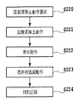
図22は、本実施形態の固着液除去動作の動作を説明するフローチャートである。まず、前回の駆動時の時間からの経過時間を取得して、予め用意された固着液除去動作から適切な塗布動作前の固着液除去動作を選択する(ステップS220)。選択された固着液除去動作に基づき、固着液を除去する(ステップS221)。そして、塗布動作(ステップS222)を行った後、塗布動作後の残存液低減動作を行なう(ステップS223)。最後に、次に塗布動作を行なう時に選択される固着液除去動作を選択するために固着液除去動作時刻を更新する(ステップS224)。
(3-4) Fixing Liquid Removal Operation FIG. 22 is a flowchart for explaining the operation of the fixing liquid removal operation of the present embodiment. First, an elapsed time from the time of the previous drive is acquired, and a fixing liquid removing operation before an appropriate coating operation is selected from a prepared fixing liquid removing operation (step S220). Based on the selected fixing liquid removing operation, the fixing liquid is removed (step S221). And after performing application | coating operation | movement (step S222), the residual liquid reduction operation | movement after application | coating operation | movement is performed (step S223). Finally, the fixing liquid removing operation time is updated in order to select the fixing liquid removing operation selected when the coating operation is performed next (step S224).

以下、詳細に本実施形態の固着液除去動作について説明する。   Hereinafter, the fixing liquid removing operation of this embodiment will be described in detail.

図23および図24は、塗布ローラ1001と当接部材2009とのニップ部を示す概略断面図である。   23 and 24 are schematic cross-sectional views showing a nip portion between the application roller 1001 and the contact member 2009. FIG.

本実施形態では、前述の塗布液の戻し動作の際、塗布液の多くは当接部材2009の上縁部2010と塗布ローラ1001との間をすり抜ける。しかしながら、当接部材2009の上縁部2010に掻き取られる塗布液もあり、塗布ローラ1001と当接部材2009とのニップ部およびその付近に残留する塗布液も存在する。また、液体の表面張力によってはまとまった滴になる場合もある。この状態で長時間放置すると、塗布液内の水分が蒸発し、塗布液が、粘度が上昇した状態で塗布ローラ1001の表面上に介在することになる。さらに、放置をし続けると、塗布液内の不揮発成分のみが残留し、塗布ローラ1001と当接部材2009とのニップ部に塗布液が固着する現象が起こる。塗布液が増粘した状態もしくは固着した状態で塗布動作を実行すると、塗布ローラ1001上の当接部材2009とのニップ部に相当する箇所のみ多量の塗布液が付着する。その結果、塗布ローラ1001上に均一な塗布液の層を形成することができず、塗布媒体Pへの塗布は不均一となる。   In the present embodiment, most of the coating liquid passes through between the upper edge portion 2010 of the contact member 2009 and the coating roller 1001 during the above-described returning operation of the coating liquid. However, some coating liquid is scraped off by the upper edge portion 2010 of the contact member 2009, and there is also a coating solution remaining in and near the nip portion between the coating roller 1001 and the contact member 2009. Also, depending on the surface tension of the liquid, it may become a coherent drop. If left in this state for a long time, the water in the coating solution evaporates, and the coating solution is interposed on the surface of the coating roller 1001 in a state where the viscosity is increased. Furthermore, if it is left unattended, only the non-volatile components in the coating liquid remain, and a phenomenon occurs in which the coating liquid adheres to the nip portion between the coating roller 1001 and the contact member 2009. When the coating operation is performed in a state where the coating liquid is thickened or fixed, a large amount of the coating liquid adheres only at a portion corresponding to the nip portion with the contact member 2009 on the coating roller 1001. As a result, a uniform coating solution layer cannot be formed on the coating roller 1001, and coating on the coating medium P becomes non-uniform.

これに対して、塗布動作前に、塗布ローラ1001が単位時間に接触する液体保持空間Sに保持されている液体の体積を塗布動作時よりも多くすることで、固着した塗布液の再溶解を促進させることが可能となる。   On the other hand, by increasing the volume of the liquid held in the liquid holding space S that the application roller 1001 contacts in unit time before the application operation, compared to the time of the application operation, the fixed application liquid can be re-dissolved. It becomes possible to promote.

本実施形態では、塗布動作前に、液体保持空間Sに塗布液を満たした状態で、塗布媒体Pを通さずに、低速度での塗布ローラ1001の回転動作を実行すること(以下「固着液除去動作」ともいう。)で、不均一な塗布を回避する。図23に示すように、塗布ローラ1001と当接部材2009とのニップ部に、塗布液が増粘・固着した状態から、図中矢印方向に塗布ローラ1001を回転させると、塗布ローラ1001上に増粘・固着した塗布液(以下「固着液」ともいう。)Tが付着する。そして、固着液Tは、図24に示されるように、液体保持空間S内に入り込む。この際、塗布ローラ1001の回転速度が低速であればあるほど、塗布ローラ1001上の固着液Tの、液体保持空間Sに保持されている塗布液Lとの接触時間が延びる。その結果、固着液Tが再溶解するため、固着液Tを除去することが可能となる。この動作は、塗布ローラ1001の1回転のうち、少なくとも、塗布ローラ1001上の、起動前に当接部材2009が当接していた位置が、液体保持空間Sを通過する間だけ低速度になっていればよい。   In the present embodiment, before the application operation, the application roller 1001 is rotated at a low speed without passing through the application medium P in a state where the liquid holding space S is filled with the application liquid (hereinafter referred to as “fixing liquid”). Also referred to as “removal operation”) to avoid non-uniform application. As shown in FIG. 23, when the application roller 1001 is rotated in the direction of the arrow in the drawing from the state where the application liquid is thickened and fixed to the nip portion between the application roller 1001 and the contact member 2009, A thickened / fixed coating solution (hereinafter also referred to as “fixing solution”) T adheres. Then, the fixing liquid T enters the liquid holding space S as shown in FIG. At this time, the lower the rotation speed of the application roller 1001, the longer the contact time of the fixing liquid T on the application roller 1001 with the application liquid L held in the liquid holding space S. As a result, since the fixing liquid T is redissolved, the fixing liquid T can be removed. In this operation, at least the position where the contact member 2009 is in contact with the application roller 1001 before starting out of one rotation of the application roller 1001 is low only while passing through the liquid holding space S. Just do it.

また、固着液除去動作の塗布ローラの回転時に、塗布ローラ1001の回転動作量を多くして、固着液Tと液体保持空間Sに介在する塗布液Lとの接触する時間を増やしてもよい。本実施形態の場合、塗布ローラ1001の回転動作量を多くすることで、副次的に、当接する部材2009の上縁部2010により固着液Tを掻き取る力も加わり、より効果的となる。   Further, during the rotation of the application roller in the fixing liquid removing operation, the rotation operation amount of the application roller 1001 may be increased to increase the contact time between the fixing liquid T and the application liquid L interposed in the liquid holding space S. In the case of the present embodiment, by increasing the amount of rotation of the application roller 1001, a force to scrape the fixing liquid T by the upper edge portion 2010 of the abutting member 2009 is added, which is more effective.

本実施形態を用いて、固着液除去動作時の塗布ローラ1001の回転動作速度および回転動作量を変更して塗布均一性を確認したデータを表2に示す。本表では、60時間放置した場合に相当する条件、および120時間放置した場合に相当する条件の下、塗布ローラ1001の周速および回転数を変えたときのデータを示している。○は塗布均一性問題無し、△はわずかに塗布不均一部あり、×は塗布不均一部あり、を示している。この結果より、固着液Tによる塗布不均一問題に対して、塗布ローラ1001の回転動作は、低速度かつ多回転量である場合が効果的であることがわかる。   Table 2 shows data in which application uniformity is confirmed by changing the rotational operation speed and the rotational operation amount of the application roller 1001 during the fixing liquid removing operation using this embodiment. This table shows data when the peripheral speed and the rotation speed of the application roller 1001 are changed under the conditions corresponding to the case where the application roller is left for 60 hours and the condition corresponding to the case where the application roller is left for 120 hours. ○ indicates that there is no coating uniformity problem, Δ indicates that there is a slight coating uneven portion, and × indicates that there is a coating uneven portion. From this result, it can be seen that the rotating operation of the applying roller 1001 is effective for the non-uniform application problem due to the fixing liquid T when the rotation speed is low and the rotation amount is large.

Figure 0005063384
Figure 0005063384

また、塗布ローラ1001上の固着液Tが、液体保持空間Sに保持されている塗布液と接触している状態(図24に示す状態)において待機時間を設けると、固着液Tの再溶解が進む。したがって、塗布ローラの回転時にローラを停止する動作を含むことも効果的である。別な制御手段として、塗布ローラ1001の回転は、図中矢印で示す正転方向のだけに限らず、逆転動作であってもよく、回転時に逆転動作を加え、それらを組み合わせて複数回行ってもよい。さらに、塗布ローラ1001の表面もしくは液体保持空間Sに保持されている塗布液の温度を上昇させる手段を有し、加温した状態で固着液を溶融させる手段も効果的である。   In addition, when a waiting time is provided in a state where the fixing liquid T on the application roller 1001 is in contact with the application liquid held in the liquid holding space S (the state shown in FIG. 24), the fixing liquid T is re-dissolved. move on. Therefore, it is also effective to include an operation of stopping the roller when the application roller rotates. As another control means, the rotation of the application roller 1001 is not limited to the forward rotation direction indicated by the arrow in the figure, and may be a reverse operation. Also good. Further, a means for increasing the temperature of the coating liquid held on the surface of the coating roller 1001 or the liquid holding space S, and a means for melting the fixing liquid in a heated state are also effective.

また、塗布ローラ1001上で固着液Tが、液体保持空間Sに保持されている塗布液と接触している状態(図24に示す状態)において、液体供給手段を用いて液体保持空間S内に塗布液の流れを発生させることも、塗布液の再溶解が促進され、効果的である。さらに、前述した手段と組み合わせて、塗布ローラ1001の駆動を停止した状態で、液体保持空間Sに塗布液の流れを発生させてもよい。   Further, in the state where the fixing liquid T is in contact with the coating liquid held in the liquid holding space S (the state shown in FIG. 24) on the application roller 1001, the liquid supply means is used to enter the liquid holding space S. Generating the flow of the coating liquid is also effective because the re-dissolution of the coating liquid is promoted. Further, in combination with the above-described means, the flow of the coating liquid may be generated in the liquid holding space S in a state where the driving of the coating roller 1001 is stopped.

本実施形態では、固着液除去動作中は、このような液体供給手段により、液体保持部材2001内の塗布液を連続的もしくは断続的に流動させることで、固着液Tの再溶解を加速させている。液体供給手段が負圧循環系であることより、ポンプ3007の回転数を上げることで、液体流路3000内および液体保持空間S内の流速が速くなると共に、見かけ上、液体保持部材2001の塗布ローラ1001に対する当接圧が強くなる。このため、副次的に、固着液Tを掻き落とす効果が高まる。   In the present embodiment, during the fixing liquid removing operation, the liquid supply means causes the coating liquid in the liquid holding member 2001 to flow continuously or intermittently, thereby accelerating re-dissolution of the fixing liquid T. Yes. Since the liquid supply means is a negative pressure circulation system, the flow rate in the liquid flow channel 3000 and the liquid holding space S is increased by increasing the number of rotations of the pump 3007, and apparently the liquid holding member 2001 is applied. The contact pressure against the roller 1001 increases. For this reason, the effect of scraping off the fixing liquid T is increased.

固着液Tの増粘・固着の度合いは、塗布液Lの水分蒸発が原因であることより、機構の放置時間によって異なる。放置時間が長ければ長いほど、増粘・固着度合いは促進する。一方、上述したように、固着液除去動作において、塗布ローラ1001の回転は、低速であればあるほど、もしくは待機時間が長いほど、固着液除去に対する効果は大きいが、塗布動作に入るまでの時間が遅くなるという不利な面もある。このため、放置時間が短い場合は、固着度合いも軽微であるため、塗布ローラ1001の回転速度もしくは回転量、待機時間を適切に選択することで、固着液除去動作の時間短縮を図ることが可能となる。   The degree of thickening and fixing of the fixing liquid T varies depending on the mechanism standing time because it is caused by the evaporation of moisture in the coating liquid L. The longer the standing time, the greater the degree of thickening and sticking. On the other hand, as described above, in the fixing liquid removing operation, the rotation of the application roller 1001 is more effective as the lower the speed or the standby time is longer. There is also the disadvantage of slowing down. For this reason, when the standing time is short, the degree of fixation is slight, and therefore the time for the fixing liquid removing operation can be shortened by appropriately selecting the rotation speed or rotation amount of the application roller 1001 and the standby time. It becomes.

すなわち、前回駆動時の時間に関する情報を取得する取得手段を有し、取得手段を用いて、固着液除去動作時にその時刻からの経過時間を算出し、その値に応じて動作条件を選択することで、効率的な固着液除去動作を行なうことができる。   That is, having an acquisition means for acquiring information related to the time of the previous drive, using the acquisition means, calculating the elapsed time from that time during the fixing liquid removing operation, and selecting the operation condition according to the value Thus, an efficient fixing liquid removal operation can be performed.

表3では、本実施形態における固着液除去シーケンスの一例を示す。本実施形態では、制御部4000の一部に不図示の電気的な記録部を具え、記録部に塗布動作終了時刻を格納し、随時最新の塗布動作終了時刻に更新する。固着液除去動作時に、前回の通紙動作の時刻を取得し、その時刻からの経過時間を算出し、その出力結果に応じて、塗布ローラ1001の回転速度および回転量を選択している。表3は、経過時間と塗布ローラ1001の駆動条件の一例を示している。本実施形態では、塗布均一性を確保しながら起動時間の効率化を実現している。加えて、固着液除去動作時にポンプ3007の回転速度を上げ、固着液Tの再溶解を促進させている。   Table 3 shows an example of the fixing liquid removal sequence in the present embodiment. In the present embodiment, an electric recording unit (not shown) is provided in a part of the control unit 4000, the application operation end time is stored in the recording unit, and updated to the latest application operation end time as needed. During the fixing liquid removing operation, the time of the previous sheet passing operation is acquired, the elapsed time from that time is calculated, and the rotation speed and rotation amount of the application roller 1001 are selected according to the output result. Table 3 shows an example of the elapsed time and the driving conditions of the application roller 1001. In this embodiment, the efficiency of the start-up time is realized while ensuring the coating uniformity. In addition, the rotational speed of the pump 3007 is increased during the fixing liquid removing operation to promote re-dissolution of the fixing liquid T.

Figure 0005063384
Figure 0005063384

さらに本実施形態では、塗布ローラ1001と当節部材2009との当接部に残存する塗布液の量を低減するために、塗布動作終了後に、塗布ローラ1001の表面上に残存する塗布液の量を低減する動作(以下、「残存液低減動作」ともいう。)を行っている。塗布ローラ1001の回転速度が遅い方がニュートンの粘性法則に従い、塗布ローラ1001上に付着する塗布液が少なくなる。また、前述のように、ポンプ3007の回転速度を上げると液体保持空間S内の負圧値が大きくなるため、塗布ローラ1001に対する当接部材2009の見かけ上の当接圧が大きくなり、液体保持部材2001より流出する塗布液の量が少なくなる。これらの動作を組み合わせることで、塗布ローラ1001上に残存する塗布液の量は、大幅に低減することができる。この結果、塗布ローラ1001と当接部材2009との間およびその付近に残存する塗布液の量が減り、固着液Tの量を低減することができる。   Furthermore, in this embodiment, in order to reduce the amount of the coating liquid remaining in the contact portion between the coating roller 1001 and the joint member 2009, the amount of the coating liquid remaining on the surface of the coating roller 1001 after the coating operation is completed. (Hereinafter, also referred to as “residual liquid reduction operation”). When the rotation speed of the coating roller 1001 is slower, the coating liquid adhering to the coating roller 1001 is reduced according to Newton's law of viscosity. Further, as described above, when the rotation speed of the pump 3007 is increased, the negative pressure value in the liquid holding space S increases, so that the apparent contact pressure of the contact member 2009 against the application roller 1001 increases, and the liquid holding The amount of the coating liquid flowing out from the member 2001 is reduced. By combining these operations, the amount of the coating liquid remaining on the coating roller 1001 can be significantly reduced. As a result, the amount of the coating liquid remaining between and near the coating roller 1001 and the contact member 2009 is reduced, and the amount of the fixing liquid T can be reduced.

なお、密閉空間を形成しない機構であっても、液面と塗布部材の接点があると、増粘現象は起こるため、上記手段が有効である。   Even if the mechanism does not form a sealed space, the above means is effective because a thickening phenomenon occurs if there is a contact between the liquid surface and the coating member.

(3−5)終了工程
再度図12に戻り、塗布媒体への塗布動作が実行されると、次に塗布工程を終了して良いか否かの判断を行う(ステップS6)。塗布工程を終了しない場合は、ステップS5に戻り、塗布媒体の塗布が必要な部分全体に塗布工程を終了するまで塗布動作を繰り返す。塗布工程を終了すると、ポンプ3007の駆動を停止させる(ステップS8)。この後、ステップS2へ移行し、塗布開始指令が入力されていれば、ステップS2〜S8の動作を繰り返す。一方、塗布開始指令が入力されていなければ、保持空間Sおよび液体流路内の塗布液を回収する回収動作などの後処理を行い(ステップS9)、塗布にかかる処理を終了する。
(3-5) Ending Step Returning to FIG. 12 again, when the coating operation on the coating medium is executed, it is next determined whether or not the coating step can be ended (step S6). If the application process is not completed, the process returns to step S5, and the application operation is repeated until the application process is completed for the entire portion where application of the application medium is required. When the coating process is finished, the driving of the pump 3007 is stopped (step S8). Thereafter, the process proceeds to step S2, and if an application start command is input, the operations in steps S2 to S8 are repeated. On the other hand, if an application start command has not been input, post-processing such as a recovery operation for recovering the application liquid in the holding space S and the liquid flow path is performed (step S9), and the application process is terminated.

なお、ステップS8でポンプ3007を停止させるのではなく、固着液除去動作での塗布ローラ1001の駆動と同期してポンプ3007を停止させるようにしてもよい。   Instead of stopping the pump 3007 in step S8, the pump 3007 may be stopped in synchronization with the driving of the application roller 1001 in the fixing liquid removing operation.

また、回収動作は、各遮断弁を「回収」の開閉組み合わせにして、ポンプ3007を一定時間駆動する。この開閉組み合わせにすると、液体保持空間Sに対して第2流路によってバッファタンク3002が連通し、また液体保持空間Sに対して第1流路は大気連通口である連通口3004と連通する。これにより、チューブ3102、液体保持空間S、チューブ3103、チューブ3104、ポンプ3007、およびチューブ3105に大気を供給することになり、充満されていた塗布液Lはバッファタンク3002に回収される。この回収動作を行うことにより、液体保持空間Sからの塗布液の蒸発を完全に防止ないしは軽減することができる。   Further, in the collecting operation, each shut-off valve is set to an opening / closing combination of “collecting”, and the pump 3007 is driven for a predetermined time. With this open / close combination, the buffer tank 3002 communicates with the liquid holding space S through the second flow path, and the first flow path communicates with the liquid holding space S with the communication port 3004 that is an air communication port. Accordingly, the atmosphere is supplied to the tube 3102, the liquid holding space S, the tube 3103, the tube 3104, the pump 3007, and the tube 3105, and the filled coating liquid L is collected in the buffer tank 3002. By performing this collecting operation, evaporation of the coating liquid from the liquid holding space S can be completely prevented or reduced.

また、回収動作後は、各遮断弁を「放置」の開閉組み合わせにする。この開閉組み合わせにすると、交換タンク3001、バッファタンク3002および液体保持空間Sは互いに遮断された状態になる。よって、移動、運搬などにおいて装置の姿勢が傾いた場合にも塗布液Lが各タンク間を移動や外部へ流出するのを完全に防止ないしは軽減することができる。   In addition, after the collecting operation, each shut-off valve is set to an open / close combination of “Left”. With this open / close combination, the exchange tank 3001, the buffer tank 3002, and the liquid holding space S are cut off from each other. Therefore, even when the posture of the apparatus is inclined during movement, transportation, etc., it is possible to completely prevent or reduce the coating liquid L from moving between tanks or flowing out to the outside.

なお、本実施形態では、交換タンク3001からバッファタンク3002への塗布液の補給と、液体保持空間Sに対する塗布液の循環とを別個に行っているが、同時に行っても良い。このときは、第2遮断弁3202は閉じ、第1遮断弁3201、第3遮断弁3203〜第5遮断弁3205を開けるようにすれば良い。   In the present embodiment, the application liquid supply from the replacement tank 3001 to the buffer tank 3002 and the application liquid circulation to the liquid holding space S are performed separately, but they may be performed simultaneously. At this time, the second cutoff valve 3202 may be closed and the first cutoff valve 3201, the third cutoff valve 3203 to the fifth cutoff valve 3205 may be opened.

(第2実施形態)
第1実施形態では、液体塗布装置について説明したが、本発明は上述の液体塗布装置を備えたインクジェット記録装置にも適用することができる。
(Second Embodiment)
Although the liquid coating apparatus has been described in the first embodiment, the present invention can also be applied to an inkjet recording apparatus including the above-described liquid coating apparatus.

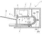
図25は、本実施形態のインクジェット記録装置を示す概略図である。本実施形態のインクジェット記録装置1には、複数枚の記録媒体Pを積載する給送トレイ2が設けられている。半月形状の分離ローラ3は、給送トレイ2に積載された記録媒体Pを1枚ずつ分離して搬送経路に給送する。搬送経路中には、液体塗布機構の液体塗布手段を構成する塗布ローラ1001およびカウンタローラ1002が配置されている。給送トレイ2から給送された記録媒体Pは、ローラ1001および1002の間に搬送される。塗布ローラ1001はローラ駆動モータの回転によって図17における時計回り方向に回転され、記録媒体Pを搬送しながら塗布液Lを記録媒体Pの記録面に塗布する。塗布液Lが塗布された記録媒体Pは、搬送ローラ4とピンチローラ5との間に送られ、搬送ローラ4が、図25における反時計周り方向へと回転することによって、記録媒体Pはプラテン6の上を搬送される。そして、記録媒体Pは、記録手段を構成する記録ヘッド7に対向する位置へと搬送される。記録ヘッド7は所定数のインク吐出用のノズルが配設されたインクジェット記録ヘッドであり、この記録ヘッド7が記録媒体Pと垂直方向に走査する間に、記録データに従ってノズルから記録媒体Pの記録面に対してインク滴が吐出される。この記録動作と搬送ローラ4による所定量の搬送動作とを交互に繰り返しながら、記録媒体P上に画像が形成される。この画像形成動作とともに、記録媒体の搬送経路において記録ヘッド7の走査領域の後流側に設けられた、排紙ローラ8と排紙拍車9によって記録媒体Pが挟持され、排紙ローラ8の回転によって排紙トレイ10上に排紙される。   FIG. 25 is a schematic view showing the ink jet recording apparatus of the present embodiment. The ink jet recording apparatus 1 of the present embodiment is provided with a feeding tray 2 on which a plurality of recording media P are stacked. The half-moon-shaped separation roller 3 separates the recording media P stacked on the feeding tray 2 one by one and feeds them to the transport path. An application roller 1001 and a counter roller 1002 that constitute liquid application means of the liquid application mechanism are disposed in the transport path. The recording medium P fed from the feeding tray 2 is conveyed between the rollers 1001 and 1002. The application roller 1001 is rotated in the clockwise direction in FIG. 17 by the rotation of the roller drive motor, and applies the application liquid L to the recording surface of the recording medium P while conveying the recording medium P. The recording medium P coated with the coating liquid L is sent between the conveying roller 4 and the pinch roller 5, and the conveying roller 4 rotates counterclockwise in FIG. 6 is carried over. Then, the recording medium P is conveyed to a position facing the recording head 7 constituting the recording means. The recording head 7 is an ink jet recording head provided with a predetermined number of nozzles for ejecting ink. While the recording head 7 scans in the direction perpendicular to the recording medium P, the recording from the nozzles to the recording medium P is recorded. Ink droplets are ejected onto the surface. An image is formed on the recording medium P while this recording operation and a predetermined amount of conveyance operation by the conveyance roller 4 are alternately repeated. Along with this image forming operation, the recording medium P is sandwiched between the discharge roller 8 and the discharge spur 9 provided on the downstream side of the scanning area of the recording head 7 in the recording medium conveyance path, and the discharge roller 8 rotates. Is discharged onto the discharge tray 10.

なお、本発明の記録装置はシリアル型のインクジェット記録装置に限定されず、例えば、インクを吐出するノズルを記録媒体の最大幅に亘って配設した長尺な記録ヘッドを用いて記録動作を行ういわゆるフルライン型のインクジェット記録装置であってもよい。   Note that the recording apparatus of the present invention is not limited to a serial type ink jet recording apparatus. For example, the recording operation is performed using a long recording head in which nozzles for ejecting ink are arranged over the maximum width of the recording medium. A so-called full-line type ink jet recording apparatus may be used.

また、本実施形態で用いる塗布液Lは、顔料を色材とするインクで記録した際に顔料の凝集を早める処理液である。塗布液として処理液を用いることにより、処理液と処理液が塗布された記録媒体Pに吐出されるインクの色材である顔料を反応させて顔料の凝集を早めさせることができる。そして、この不溶化により、記録濃度の向上を図ることができる。さらに、ブリーディングの軽減または防止が可能となる。なお、インクジェット記録装置において用いる塗布液としては、上述の例に限られないことは勿論である。   Further, the coating liquid L used in the present embodiment is a processing liquid that accelerates the aggregation of the pigment when recording with the ink using the pigment as the color material. By using the treatment liquid as the coating liquid, the pigment that is the color material of the ink discharged to the recording medium P coated with the treatment liquid can be reacted to accelerate the aggregation of the pigment. This insolubilization can improve the recording density. Furthermore, bleeding can be reduced or prevented. Needless to say, the coating liquid used in the ink jet recording apparatus is not limited to the above example.

図26は、本実施形態のインクジェット記録装置の要部を示す斜視図である。給送トレイ2の一端の上方に塗布機構100が設けられ、この塗布機構より上部に給送トレイ2の中央部上方に記録ヘッド7などを備えた記録機構が設けられる。   FIG. 26 is a perspective view showing a main part of the ink jet recording apparatus of the present embodiment. A coating mechanism 100 is provided above one end of the feeding tray 2, and a recording mechanism including a recording head 7 and the like is provided above the coating mechanism and above the central portion of the feeding tray 2.

図27は、本実施形態のインクジェット記録装置の制御系の概略構成を示すブロック図である。液体塗布機構の要素であるローラ駆動モータ1004、ポンプ駆動モータ4009は、第1実施形態の液体塗布装置と同様の要素である。CPU5001は、後述する処理手順に従い、塗布機構の各要素の駆動を制御する。またCPU5001は、記録機構にかかるLFモータ5013、CRモータ5015、および記録ヘッド7の駆動を、それぞれの駆動回路5012、5014、5016を介して制御する。すなわち、LFモータ5013の駆動によって搬送ローラ4などを回転させ、また、CRモータ5015の駆動によって記録ヘッド7を搭載したキャリッジを移動させる。さらに、記録ヘッド7のノズルからインクを吐出させる制御を行う。   FIG. 27 is a block diagram illustrating a schematic configuration of a control system of the ink jet recording apparatus according to the present embodiment. The roller drive motor 1004 and the pump drive motor 4009 that are elements of the liquid application mechanism are the same elements as the liquid application apparatus of the first embodiment. The CPU 5001 controls driving of each element of the coating mechanism according to a processing procedure described later. The CPU 5001 controls driving of the LF motor 5013, the CR motor 5015, and the recording head 7 according to the recording mechanism via the respective drive circuits 5012, 5014, and 5016. That is, the conveyance roller 4 and the like are rotated by driving the LF motor 5013, and the carriage on which the recording head 7 is mounted is moved by driving the CR motor 5015. Further, control is performed to eject ink from the nozzles of the recording head 7.

図28は、本実施形態のインクジェット記録装置における液体塗布およびそれに伴う記録動作の手順を示すフローチャートである。   FIG. 28 is a flowchart showing the procedure of liquid application and the accompanying recording operation in the inkjet recording apparatus of the present embodiment.

同図において、ステップS101、S103〜S105の処理、およびステップS108〜S110の処理は、それぞれ、第1実施形態の図12に示すステップS1、S3〜S5、S8〜S9の処理と同様である。   In the same figure, the process of step S101, S103-S105, and the process of step S108-S110 are the same as the process of step S1, S3-S5, and S8-S9 shown in FIG. 12 of 1st Embodiment, respectively.

図28に示すように、本実施形態では、記録開始の指令があると(ステップS102)、ポンプ作動などの一連の液体塗布動作を行う(ステップS103〜S105)。そして、記録媒体の液体塗布が必要な部分に液体を塗布する。塗布動作の前後では、必要に応じて前述した固着液除去動作を行う。   As shown in FIG. 28, in this embodiment, when there is a recording start command (step S102), a series of liquid application operations such as pump operation are performed (steps S103 to S105). Then, a liquid is applied to a portion of the recording medium that requires liquid application. Before and after the coating operation, the above-described fixing liquid removing operation is performed as necessary.

この塗布工程の後、必要な部分に塗布液が塗布された記録媒体に対して、記録動作を行う(ステップS106)。すなわち、搬送ローラ4によって所定量ずつ搬送される記録媒体Pに対して記録ヘッド7を走査させ、この走査の間に記録データに応じてノズルからインクを吐出することにより記録媒体にインクを付着させてドットを形成する。この付着するインクは塗布液と反応するため、濃度向上や滲みの防止が可能となる。以上の記録媒体の搬送と記録ヘッドの走査を繰り返すことにより、記録媒体Pに対して記録がなされ、記録を終了した記録媒体は排紙トレイ10上に排紙される。ステップS107で記録が終了したと判断すると、ステップS108以降の処理を行い、本処理を終了する。   After this coating process, a recording operation is performed on the recording medium in which the coating liquid is coated on a necessary portion (step S106). That is, the recording head 7 is scanned with respect to the recording medium P conveyed by a predetermined amount by the conveying roller 4, and ink is attached to the recording medium by ejecting ink from the nozzles according to the recording data during this scanning. To form dots. Since the adhering ink reacts with the coating liquid, it is possible to improve the density and prevent bleeding. By repeating the above-described conveyance of the recording medium and scanning of the recording head, recording is performed on the recording medium P, and the recording medium that has finished recording is discharged onto the discharge tray 10. If it is determined in step S107 that the recording has been completed, the processing after step S108 is performed, and this processing is terminated.

なお、本実施形態では、記録媒体に対する液体塗布に伴い、その塗布が終了した部分に対して順次記録を行うものである。すなわち、塗布ローラから記録ヘッドへ至る搬送経路の長さが記録媒体の長さよりも短く、記録媒体上の液体の塗布がなされた部分が記録ヘッドによる走査領域に至るときに、記録媒体の他の部分に塗布機構によって塗布が行われる形態である。この形態により、記録媒体の所定量の搬送ごとに、記録媒体の異なる部分で、順次、液体塗布と記録がなされていくものである。しかしながら、本発明はこのような形態に限定されず、1つの記録媒体に対する塗布が完了してから記録を行うものであってもよい。   In the present embodiment, recording is sequentially performed on a portion where the application has been completed as the liquid application is performed on the recording medium. That is, when the length of the conveyance path from the application roller to the recording head is shorter than the length of the recording medium, and the portion where the liquid is applied on the recording medium reaches the scanning area by the recording head, In this mode, application is performed on the portion by an application mechanism. With this configuration, each time a predetermined amount of the recording medium is conveyed, liquid application and recording are sequentially performed on different portions of the recording medium. However, the present invention is not limited to such a form, and recording may be performed after application to one recording medium is completed.

また、本実施形態の記録装置では、液体塗布機構によって、蛍光増白剤を含有する液体を塗布することにより、媒体の白色度を向上させることもできる。このとき、液体塗布後の記録手段は、インクジェット記録方式に限られず、熱転写方式、電子写真方式などの記録方式でも効果を得ることができる。また、銀塩写真方式の記録装置に適用する場合には、記録前に感光剤を塗布してもよい。   In the recording apparatus of the present embodiment, the whiteness of the medium can be improved by applying a liquid containing a fluorescent brightening agent by the liquid application mechanism. At this time, the recording means after applying the liquid is not limited to the ink jet recording system, and an effect can also be obtained by a recording system such as a thermal transfer system or an electrophotographic system. When applied to a silver halide photographic recording apparatus, a photosensitive agent may be applied before recording.

すなわち、本発明は、インクジェット記録装置に適用する場合に限定されるものではなく、記録媒体に処理液等の液体を塗布する機構を有する記録装置に適用されるものである。   That is, the present invention is not limited to application to an ink jet recording apparatus, but is applied to a recording apparatus having a mechanism for applying a liquid such as a processing liquid to a recording medium.

本発明の第1実施形態の液体塗布機構の全体構成を示す斜視図である。It is a perspective view which shows the whole structure of the liquid application mechanism of 1st Embodiment of this invention. 本発明の第1の実施形態の塗布ローラ、カウンタローラおよび液体保持部材の配置の例を示す縦断側面図である。It is a vertical side view which shows the example of arrangement | positioning of the application roller of the 1st Embodiment of this invention, a counter roller, and a liquid holding member. 本発明の第1の実施形態の液体保持部材の構成を示す正面図である。It is a front view which shows the structure of the liquid holding member of the 1st Embodiment of this invention. 図3のA−A線にて切断した端面を示す端面図である。It is an end view which shows the end surface cut | disconnected by the AA line of FIG. 図3のB−B線にて切断した端面を示す端面図である。It is an end elevation which shows the end surface cut | disconnected by the BB line of FIG. 本発明の第1の実施形態の液体保持部材の構成を示す平面図である。It is a top view which shows the structure of the liquid holding member of the 1st Embodiment of this invention. 本発明の第1の実施形態の液体塗布部材の当接部を液体塗布ローラに当接させた状態を示す左側面図である。It is a left view which shows the state which contacted the contact part of the liquid application member of the 1st Embodiment of this invention to the liquid application roller. 本発明の第1の実施形態の液体塗布部材の当接部を液体塗布ローラに当接させた状態を示す右側面図である。It is a right view which shows the state which contact | abutted the contact part of the liquid application member of the 1st Embodiment of this invention to the liquid application roller. 本発明の第1実施形態の液体流路の概略構成を示す説明図である。It is explanatory drawing which shows schematic structure of the liquid flow path of 1st Embodiment of this invention. 本発明の第1実施形態の液体検知センサを示す概略断面図である。It is a schematic sectional drawing which shows the liquid detection sensor of 1st Embodiment of this invention. 本発明の第1実施形態の液体塗布装置における制御系の概略構成を示すブロック図である。It is a block diagram which shows schematic structure of the control system in the liquid coating device of 1st Embodiment of this invention. 本発明の第1実施形態の液体塗布装置における液体塗布の処理手順を示すフローチャートである。It is a flowchart which shows the process sequence of the liquid application in the liquid application apparatus of 1st Embodiment of this invention. 本発明の第1実施形態の充填工程の動作の詳細を示すフローチャートである。It is a flowchart which shows the detail of operation | movement of the filling process of 1st Embodiment of this invention. 本発明の第1実施形態のバッファタンクの構成を示す概略図である。It is the schematic which shows the structure of the buffer tank of 1st Embodiment of this invention. 本発明の第1実施形態のバッファタンクの構成を示す概略図である。It is the schematic which shows the structure of the buffer tank of 1st Embodiment of this invention. 本発明の第1実施形態のバッファタンクの構成を示す概略図である。It is the schematic which shows the structure of the buffer tank of 1st Embodiment of this invention. 本発明の第1実施形態の液体塗布手段の構成を示す縦断面図である。It is a longitudinal cross-sectional view which shows the structure of the liquid application means of 1st Embodiment of this invention. 本発明の第1実施形態の液体塗布手段の構成を示す縦断面図である。It is a longitudinal cross-sectional view which shows the structure of the liquid application means of 1st Embodiment of this invention. 本発明の第1実施形態の媒体の表面と塗布面での塗布過程を説明する説明図である。It is explanatory drawing explaining the application | coating process by the surface and application | coating surface of the medium of 1st Embodiment of this invention. 本発明の第1実施形態の媒体の表面と塗布面での塗布過程を説明する説明図である。It is explanatory drawing explaining the application | coating process by the surface and application | coating surface of the medium of 1st Embodiment of this invention. 本発明の第1実施形態の媒体の表面と塗布面での塗布過程を説明する説明図である。It is explanatory drawing explaining the application | coating process by the surface and application | coating surface of the medium of 1st Embodiment of this invention. 本発明の第1実施形態の固着液除去動作の動作を説明するフローチャートである。It is a flowchart explaining the operation | movement of the fixing liquid removal operation | movement of 1st Embodiment of this invention. 本発明の第1実施形態の塗布ローラと当接部材とのニップ部を示す概略断面図である。It is a schematic sectional drawing which shows the nip part of the application roller and contact member of 1st Embodiment of this invention. 本発明の第1実施形態の塗布ローラと当接部材とのニップ部を示す概略断面図である。It is a schematic sectional drawing which shows the nip part of the application roller and contact member of 1st Embodiment of this invention. 本発明の第2実施形態のインクジェット記録装置を示す概略図である。It is the schematic which shows the inkjet recording device of 2nd Embodiment of this invention. 本発明の第2実施形態のインクジェット記録装置の要部を示す斜視図である。It is a perspective view which shows the principal part of the inkjet recording device of 2nd Embodiment of this invention. 本発明の第2実施形態のインクジェット記録装置の制御系の概略構成を示すブロック図であるIt is a block diagram which shows schematic structure of the control system of the inkjet recording device of 2nd Embodiment of this invention. 本発明の第2実施形態のインクジェット記録装置における液体塗布およびそれに伴う記録動作の手順を示すフローチャートである。It is a flowchart which shows the procedure of the liquid application | coating and accompanying recording operation | movement in the inkjet recording device of 2nd Embodiment of this invention.

符号の説明Explanation of symbols

Y001 液体検知センサ
1 インクジェット記録装置
2 給紙トレイ
3 分離ローラ
4 搬送ローラ
7 記録部
2001 液体保持部材
2002 空間形成部材
2004 液体供給口
2005 液体回収口
2009 当接部材
3000 液体流路
3001 交換タンク
3002 バッファタンク
3007 ポンプ
3008 連通口
3101 供給流路
3105 回収流路
4000 制御部
4009 ポンプ駆動モータ
5001 CPU
L 塗布液
P 塗布媒体
S 液体保持空間
Y001 Liquid detection sensor 1 Inkjet recording device 2 Paper feed tray 3 Separating roller 4 Conveying roller 7 Recording unit 2001 Liquid holding member 2002 Space forming member 2004 Liquid supply port 2005 Liquid recovery port 2009 Abutting member 3000 Liquid flow channel 3001 Exchange tank 3002 Buffer Tank 3007 Pump 3008 Communication port 3101 Supply flow path 3105 Recovery flow path 4000 Control unit 4009 Pump drive motor 5001 CPU
L Coating liquid P Coating medium S Liquid holding space

Claims (10)

塗布面に供給された液体を記録媒体に塗布する塗布動作を行なう塗布ローラと、
前記塗布面に当接して前記液体を保持する液体保持空間を形成する液体保持部材と
前記塗布動作よりも前に、前記塗布ローラの回転を伴って、前記塗布面に付着した固着液を前記液体保持空間内の前記液体に接触させることより前記固着液を溶解させる固着液除去動作を行なう制御部と、
を具える液体塗布装置であって、
前記制御部は、前記塗布面の部分が前記液体保持空間を通過する間に前記液体と接触する時間が、前記塗布動作時よりも前記固着液除去動作時の方が長くなるように、前記塗布ローラの回転を制御することを特徴とする液体塗布装置。
An application roller for performing an application operation for applying the liquid supplied to the application surface to the recording medium;
A liquid holding member that forms a liquid holding space for holding the liquid in contact with the application surface ;
Prior to the application operation, a fixing liquid removing operation for dissolving the fixing liquid by bringing the fixing liquid attached to the application surface into contact with the liquid in the liquid holding space with the rotation of the application roller. A control unit to perform;
A liquid application device comprising:
The controller is configured so that the time during which the portion of the application surface contacts the liquid while passing through the liquid holding space is longer during the fixing liquid removal operation than during the application operation. A liquid application apparatus that controls rotation of a roller .
前記液体保持空間に保持される液体の体積、前記塗布動作時より前記固着液除去動作時の方が多いことを特徴とする請求項1に記載の液体塗布装置。 The volume of liquid held in the liquid holding space, a liquid coating apparatus according to claim 1, characterized in that towards the fixedly adhered liquid removing operation than during the coating operation is large. 前記塗布ローラの回転速度、前記塗布動作時より前記固着液除去動作時の方が低いことを特徴とする請求項1または2に記載の液体塗布装置。 The rotational speed of the application roller, a liquid coating apparatus according to claim 1 or 2, wherein said that the person at the time of the fixedly adhered liquid removing operation is lower than during the coating operation. 前記固着液除去動作時の前記塗布ローラの回転動作は当該塗布ローラの回転が停止する動作を含むことを特徴とする請求項1から請求項のいずれかに記載の液体塗布装置。 The rotation of the applying roller during fixedly adhered liquid removing operation, the liquid coating apparatus according to any one of claims 1 to 3, rotation of the application roller, characterized in that it comprises an operation to stop. 前記固着液除去動作時の前記塗布ローラの回転動作は当該塗布ローラの回転が前記塗布動作時の回転と逆に回転する動作を含むことを特徴とする請求項1から請求項のいずれかに記載の液体塗布装置。 Said rotation of the coating roller at the time of the fixedly adhered liquid removing operation, any one of claims 1 to rotation of the application roller, characterized in that it comprises an operation of rotating the rotation and reverse during the coating operation according to claim 4 The liquid coating apparatus according to 1. 前記制御部は、前記固着液除去動作時に、前記液体保持空間に保持された液体に流れを発生させることを特徴とする請求項1から請求項のいずれかに記載の液体塗布装置。 Wherein, when the fixedly adhered liquid removing operation, the liquid coating apparatus according to any one of claims 1 to 5, characterized in that to generate a flow in the liquid held in the liquid holding space. 前記液体塗布装置は、さらに塗布動作後に前記塗布ローラを回転させ、前記塗布動作後の前記塗布ローラの回転は、前記塗布動作時の前記塗布ローラの回転よりも回転速度が低速であることを特徴とする請求項1から請求項のいずれかに記載の液体塗布装置。 Wherein the liquid coating apparatus, is further rotated to the coating roller after coating operation, the rotation of the application roller after the coating operation, the rotational speed than the rotation of the application roller during the coating operation is slow The liquid coating apparatus according to any one of claims 1 to 6 . 前記塗布面の部分が前記液体保持空間を通過する間に前記液体と接触する時間は、前回の塗布動作からの経過時間に基づき変更することを特徴とする請求項1から請求項のいずれかに記載の液体塗布装置。 Time portion of the coated surface is in contact with the liquid while passing through the liquid holding space is, any one of claims 1, characterized in that the change on the basis of the elapsed time from the previous coating operation according to claim 7 The liquid coating apparatus according to 1. 記録媒体を所定の搬送経路に沿って搬送する搬送手段と、前記記録媒体に記録を行なう記録手段と、前記記録媒体に液体を塗布する液体塗布手段とを備えた記録装置であって、
前記液体塗布手段は、
塗布面に供給された液体を記録媒体に塗布する塗布動作を行なう塗布ローラと、
前記塗布面に当接して前記液体を保持する液体保持空間を形成する液体保持部材と
前記塗布動作よりも前に、前記塗布ローラの回転を伴って、前記塗布面に付着した固着液を前記液体保持空間内の前記液体に接触させることより前記固着液を溶解させる固着液除去動作を行なう制御部と、
を具える液体塗布手段であって、
前記制御部は、前記塗布面の部分が前記液体保持空間を通過する間に前記液体と接触する時間が、前記塗布動作時よりも前記固着液除去動作時の方が長くなるように、前記塗布ローラの回転を制御することを特徴とする記録装置。
A recording apparatus comprising: conveying means for conveying a recording medium along a predetermined conveying path; recording means for recording on the recording medium; and liquid applying means for applying a liquid to the recording medium,
The liquid applying means includes
An application roller for performing an application operation for applying the liquid supplied to the application surface to the recording medium;
A liquid holding member that forms a liquid holding space for holding the liquid in contact with the application surface ;
Prior to the application operation, a fixing liquid removing operation for dissolving the fixing liquid by bringing the fixing liquid attached to the application surface into contact with the liquid in the liquid holding space with the rotation of the application roller. A control unit to perform;
A liquid application means comprising:
The controller is configured so that the time during which the portion of the application surface contacts the liquid while passing through the liquid holding space is longer during the fixing liquid removal operation than during the application operation. A recording apparatus for controlling rotation of a roller .
前記搬送経路において、前記液体塗布手段は、前記記録手段よりも上流側に配置されたことを特徴とする請求項に記載の記録装置。 The recording apparatus according to claim 9 , wherein the liquid application unit is disposed upstream of the recording unit in the transport path.
JP2008013066A 2008-01-23 2008-01-23 Liquid coating apparatus and recording apparatus Active JP5063384B2 (en)

Priority Applications (4)

Application Number Priority Date Filing Date Title
JP2008013066A JP5063384B2 (en) 2008-01-23 2008-01-23 Liquid coating apparatus and recording apparatus
EP09151114.7A EP2082810B1 (en) 2008-01-23 2009-01-22 Liquid application apparatus and printing apparatus
US12/357,876 US8146529B2 (en) 2008-01-23 2009-01-22 Liquid application apparatus and printing apparatus
CN2009100011842A CN101491980B (en) 2008-01-23 2009-01-23 Liquid application apparatus and printing apparatus

Applications Claiming Priority (1)

Application Number Priority Date Filing Date Title
JP2008013066A JP5063384B2 (en) 2008-01-23 2008-01-23 Liquid coating apparatus and recording apparatus

Publications (3)

Publication Number Publication Date
JP2009172840A JP2009172840A (en) 2009-08-06
JP2009172840A5 JP2009172840A5 (en) 2011-01-20
JP5063384B2 true JP5063384B2 (en) 2012-10-31

Family

ID=40513910

Family Applications (1)

Application Number Title Priority Date Filing Date
JP2008013066A Active JP5063384B2 (en) 2008-01-23 2008-01-23 Liquid coating apparatus and recording apparatus

Country Status (4)

Country Link
US (1) US8146529B2 (en)
EP (1) EP2082810B1 (en)
JP (1) JP5063384B2 (en)
CN (1) CN101491980B (en)

Families Citing this family (11)

* Cited by examiner, † Cited by third party
Publication number Priority date Publication date Assignee Title
JP5441341B2 (en) * 2008-01-23 2014-03-12 キヤノン株式会社 Liquid coating apparatus and method for controlling liquid coating apparatus
JP5063385B2 (en) * 2008-01-23 2012-10-31 キヤノン株式会社 Liquid coating apparatus and inkjet recording apparatus
US20100154706A1 (en) * 2008-12-19 2010-06-24 Canon Kabushiki Kaisha Liquid applying apparatus
JP5794466B2 (en) 2011-04-13 2015-10-14 株式会社リコー Treatment liquid applying apparatus and image forming apparatus
JP6028433B2 (en) * 2012-07-17 2016-11-16 株式会社リコー Treatment liquid coating device for inkjet printer, inkjet system
JP6201479B2 (en) * 2013-07-22 2017-09-27 株式会社リコー Treatment liquid application device for inkjet printer
JP6327882B2 (en) 2014-02-25 2018-05-23 キヤノン株式会社 Recording device
JP6116525B2 (en) 2014-06-10 2017-04-19 キヤノン株式会社 Carriage device
JP2023020127A (en) 2021-07-30 2023-02-09 キヤノン株式会社 Hand-held type recording device
JP2023020124A (en) 2021-07-30 2023-02-09 キヤノン株式会社 Hand-held type recorder
JP2023020119A (en) 2021-07-30 2023-02-09 キヤノン株式会社 Hand-held type recording device

Family Cites Families (12)

* Cited by examiner, † Cited by third party
Publication number Priority date Publication date Assignee Title
US3952700A (en) * 1970-11-09 1976-04-27 Xerox Corporation Liquid applicator
JP3184050B2 (en) 1994-08-24 2001-07-09 富士機械工業株式会社 Ink supply device for gravure printing press
JPH0872227A (en) 1994-09-02 1996-03-19 Canon Inc Image forming apparatus
US6183079B1 (en) * 1998-06-11 2001-02-06 Lexmark International, Inc. Coating apparatus for use in an ink jet printer
JP2001070858A (en) 1999-07-07 2001-03-21 Canon Inc Paint coater and coating method
JP4025004B2 (en) 2000-09-22 2007-12-19 株式会社リコー Image recording device
US6706118B2 (en) * 2002-02-26 2004-03-16 Lexmark International, Inc. Apparatus and method of using motion control to improve coatweight uniformity in intermittent coaters in an inkjet printer
JP4498148B2 (en) * 2004-02-12 2010-07-07 キヤノン株式会社 Liquid applicator, recording device
JP2006346534A (en) * 2005-06-14 2006-12-28 Canon Inc Liquid applying apparatus and recording apparatus
WO2007018274A1 (en) * 2005-08-11 2007-02-15 Canon Kabushiki Kaisha Liquid coater, inkjet recording device and controlling method for liquid coater
JP4480166B2 (en) * 2005-08-11 2010-06-16 キヤノン株式会社 Liquid coating apparatus and inkjet recording apparatus
JP4845499B2 (en) * 2005-12-07 2011-12-28 キヤノン株式会社 Inkjet recording apparatus and recording apparatus

Also Published As

Publication number Publication date
EP2082810B1 (en) 2013-07-10
EP2082810A3 (en) 2009-12-30
US20090194019A1 (en) 2009-08-06
US8146529B2 (en) 2012-04-03
JP2009172840A (en) 2009-08-06
CN101491980A (en) 2009-07-29
EP2082810A2 (en) 2009-07-29
CN101491980B (en) 2011-03-16

Similar Documents

Publication Publication Date Title
JP5063384B2 (en) Liquid coating apparatus and recording apparatus
JP5441341B2 (en) Liquid coating apparatus and method for controlling liquid coating apparatus
JP4533274B2 (en) Liquid coating apparatus and inkjet recording apparatus
JP4533275B2 (en) Liquid coating apparatus and inkjet recording apparatus
JP4498148B2 (en) Liquid applicator, recording device
US7650850B2 (en) Liquid applying apparatus and ink jet printing apparatus
JP4617383B2 (en) Inkjet recording device
JP5414356B2 (en) Ink jet recording apparatus, liquid application mechanism, and control method of the liquid application mechanism
JP5116471B2 (en) Liquid coating apparatus and inkjet recording apparatus
JPWO2007018274A1 (en) Liquid coating apparatus, inkjet recording apparatus, and liquid coating apparatus control method
JP2007050315A (en) Liquid coater and ink jet recording apparatus
JP4355586B2 (en) Liquid coating apparatus and inkjet recording apparatus
JP4677246B2 (en) Inkjet recording device
JP5371226B2 (en) Liquid coating apparatus and inkjet recording apparatus
JP2010143014A (en) Recording apparatus and recording method
JP2010274255A (en) Liquid storage container, coating liquid feed system and inkjet recording device
JP4748768B2 (en) Inkjet recording device
JP4906460B2 (en) Liquid applicator
JP4642360B2 (en) Liquid applicator, recording device
JP2008149231A (en) Liquid coater and ink jet recorder
JP4355662B2 (en) Inkjet recording device
JP4533120B2 (en) Liquid coating apparatus and inkjet recording apparatus
JP4508978B2 (en) Liquid coating apparatus and inkjet recording apparatus
JP6515540B2 (en) Liquid application apparatus and image forming system
JP2005224701A (en) Liquid coating device and inkjet recording device

Legal Events

Date Code Title Description
RD02 Notification of acceptance of power of attorney

Free format text: JAPANESE INTERMEDIATE CODE: A7422

Effective date: 20101106

A521 Written amendment

Free format text: JAPANESE INTERMEDIATE CODE: A523

Effective date: 20101201

A621 Written request for application examination

Free format text: JAPANESE INTERMEDIATE CODE: A621

Effective date: 20101201

A977 Report on retrieval

Free format text: JAPANESE INTERMEDIATE CODE: A971007

Effective date: 20120411

A131 Notification of reasons for refusal

Free format text: JAPANESE INTERMEDIATE CODE: A131

Effective date: 20120420

A521 Written amendment

Free format text: JAPANESE INTERMEDIATE CODE: A523

Effective date: 20120619

TRDD Decision of grant or rejection written
A01 Written decision to grant a patent or to grant a registration (utility model)

Free format text: JAPANESE INTERMEDIATE CODE: A01

Effective date: 20120710

A01 Written decision to grant a patent or to grant a registration (utility model)

Free format text: JAPANESE INTERMEDIATE CODE: A01

A61 First payment of annual fees (during grant procedure)

Free format text: JAPANESE INTERMEDIATE CODE: A61

Effective date: 20120807

R151 Written notification of patent or utility model registration

Ref document number: 5063384

Country of ref document: JP

Free format text: JAPANESE INTERMEDIATE CODE: R151

FPAY Renewal fee payment (event date is renewal date of database)

Free format text: PAYMENT UNTIL: 20150817

Year of fee payment: 3