JP4480166B2 - Liquid coating apparatus and inkjet recording apparatus - Google Patents
Liquid coating apparatus and inkjet recording apparatus Download PDFInfo
- Publication number
- JP4480166B2 JP4480166B2 JP2005233271A JP2005233271A JP4480166B2 JP 4480166 B2 JP4480166 B2 JP 4480166B2 JP 2005233271 A JP2005233271 A JP 2005233271A JP 2005233271 A JP2005233271 A JP 2005233271A JP 4480166 B2 JP4480166 B2 JP 4480166B2
- Authority
- JP
- Japan
- Prior art keywords
- liquid
- application
- coating
- roller
- holding member
- Prior art date
- Legal status (The legal status is an assumption and is not a legal conclusion. Google has not performed a legal analysis and makes no representation as to the accuracy of the status listed.)
- Active
Links
Images


Classifications
-
- B—PERFORMING OPERATIONS; TRANSPORTING
- B41—PRINTING; LINING MACHINES; TYPEWRITERS; STAMPS
- B41J—TYPEWRITERS; SELECTIVE PRINTING MECHANISMS, i.e. MECHANISMS PRINTING OTHERWISE THAN FROM A FORME; CORRECTION OF TYPOGRAPHICAL ERRORS
- B41J29/00—Details of, or accessories for, typewriters or selective printing mechanisms not otherwise provided for
- B41J29/17—Cleaning arrangements
-
- B—PERFORMING OPERATIONS; TRANSPORTING
- B41—PRINTING; LINING MACHINES; TYPEWRITERS; STAMPS
- B41F—PRINTING MACHINES OR PRESSES
- B41F31/00—Inking arrangements or devices
- B41F31/02—Ducts, containers, supply or metering devices
- B41F31/027—Ink rail devices for inking ink rollers
-
- B—PERFORMING OPERATIONS; TRANSPORTING
- B41—PRINTING; LINING MACHINES; TYPEWRITERS; STAMPS
- B41J—TYPEWRITERS; SELECTIVE PRINTING MECHANISMS, i.e. MECHANISMS PRINTING OTHERWISE THAN FROM A FORME; CORRECTION OF TYPOGRAPHICAL ERRORS
- B41J11/00—Devices or arrangements of selective printing mechanisms, e.g. ink-jet printers or thermal printers, for supporting or handling copy material in sheet or web form
- B41J11/0015—Devices or arrangements of selective printing mechanisms, e.g. ink-jet printers or thermal printers, for supporting or handling copy material in sheet or web form for treating before, during or after printing or for uniform coating or laminating the copy material before or after printing
-
- B—PERFORMING OPERATIONS; TRANSPORTING
- B41—PRINTING; LINING MACHINES; TYPEWRITERS; STAMPS
- B41J—TYPEWRITERS; SELECTIVE PRINTING MECHANISMS, i.e. MECHANISMS PRINTING OTHERWISE THAN FROM A FORME; CORRECTION OF TYPOGRAPHICAL ERRORS
- B41J2/00—Typewriters or selective printing mechanisms characterised by the printing or marking process for which they are designed
- B41J2/005—Typewriters or selective printing mechanisms characterised by the printing or marking process for which they are designed characterised by bringing liquid or particles selectively into contact with a printing material
- B41J2/01—Ink jet
- B41J2/17—Ink jet characterised by ink handling
- B41J2/175—Ink supply systems ; Circuit parts therefor
- B41J2/17503—Ink cartridges
- B41J2/17506—Refilling of the cartridge
- B41J2/17509—Whilst mounted in the printer
Description
本発明は、液体塗布装置およびインクジェット記録装置に関する。詳しくは、顔料を色材とするインクで記録した際に顔料の凝集を早めるなど所定の目的で媒体に液体を塗布する液体塗布装置に関するものである。また、同様に、インクジェット記録で用いられる記録媒体に対して、顔料を色材とするインクで記録した際に顔料の凝集を早めるなどの目的で液体を塗布する機構を備えたインクジェット記録装置に関するものである。 The present invention relates to a liquid coating apparatus and an ink jet recording apparatus. More specifically, the present invention relates to a liquid application apparatus that applies a liquid to a medium for a predetermined purpose such as aggregating the pigment when recording with an ink using a pigment as a color material. Similarly, the present invention relates to an ink jet recording apparatus provided with a mechanism for applying a liquid for the purpose of accelerating the aggregation of the pigment when recording with the ink using the pigment as a coloring material on the recording medium used in the ink jet recording. It is.
広く媒体に液体もしくは液状の材料を塗布する方式として、スピンコータ、ロールコータ、バーコータ、ダイコータが知られている。これらの塗布方式は、その搬送方向の長さが比較的長い塗布媒体に塗布を連続的に行うことを前提としたものである。このため、例えば、比較的小さなサイズの塗布媒体が断続的に搬送されてこれらに塗布を行う場合には、塗布媒体ごとに、その塗布開始や終了の位置で塗料ビードが乱れるなどして均一な塗膜が得られなくなるなどの問題を生じることがある。 Spin coaters, roll coaters, bar coaters, and die coaters are widely known as methods for applying a liquid or liquid material to a medium. These coating methods are based on the premise that coating is continuously performed on a coating medium having a relatively long length in the transport direction. For this reason, for example, when a relatively small size application medium is intermittently transported and applied to these, the coating bead is disturbed at the start and end positions of the application medium, for example. Problems such as the inability to obtain a coating film may occur.
このような問題を解消できる一構成として、特許文献1に記載されたものが知られている。この構成は、ダイコーダ方式において、回転するロッドバーを用い、このロッドバーに対して吐出用スリットから塗料を吐出し、ロッドバー上に塗膜を形成する。そして、形成された塗膜はロッドバーの回転に伴い塗布媒体に接触して転写されるものである。ここで、ロッドバーに形成された塗膜を塗布媒体に転写、塗布しないときは、塗料はロッドバーの回転によりヘッド内に戻り回収用スリットを介して回収される。すなわち、非塗布時でもロッドバーは回転し続け、その際、塗料はロッドバーに塗膜を形成した状態にある。これにより、塗布媒体が断続的に供給されそれらに断続的に塗布を行う場合でも、均一な塗膜を得ることを可能としている。 As one configuration capable of solving such a problem, one described in Patent Document 1 is known. This configuration uses a rotating rod bar in a die coder system, and discharges paint from the discharge slit to the rod bar to form a coating film on the rod bar. The formed coating film is transferred in contact with the coating medium as the rod bar rotates. Here, when the coating film formed on the rod bar is not transferred or applied to the coating medium, the coating material returns to the head by the rotation of the rod bar and is collected through the collecting slit. That is, the rod bar continues to rotate even when it is not applied, and the paint is in a state where a coating film is formed on the rod bar. This makes it possible to obtain a uniform coating film even when the coating medium is intermittently supplied and the coating medium is intermittently applied thereto.
インクジェット記録装置の分野においても液体塗布機構を用いたものが知られている。特許文献2には、ローラと接するドクターブレードを用い、このブレードとローラとの間にコーティング液を溜めるようにし、ローラの回転に伴ってこのローラにコーティング液が付与されることが記載されている。そして、ローラの回転に伴い、これと他のローラとの間を搬送される支持体に対し、ローラに付与されたコーティング液が転写、塗布される。特許文献3にも、同様に、インクジェット記録装置において、染料を不溶化する処理液を記録の前に予め塗布する機構が示されている。この文献の実施例1には、補充タンクに有る処理液が、回転するローラに付着することによって汲み出され同時にその汲み出した処理液が記録紙に塗布されることが記載されている。
Also in the field of ink jet recording apparatuses, those using a liquid application mechanism are known.
しかし、以上の特許文献1ないし3に記載の構成は、いずれも、ロッドバーないしローラが回転しつつそのバーないしローラの表面に塗布液が付与もしくは供給されるが、その付与等する部分が大気に開放されあるいは連通した部分である。このため、塗布液の蒸発などが問題となる他、装置の姿勢が変わったときに、それによって塗布液が漏れるなどの問題を生じるおそれがある。特に、プリンタなどのインクジェット記録装置では、運搬時の姿勢変化による液体の漏れなどを考慮すると、小型化された装置には上記各文献に記載の塗布機構を適用し難い。 However, in all of the configurations described in Patent Documents 1 to 3, the coating liquid is applied or supplied to the surface of the bar or roller while the rod bar or roller rotates. An open or communicated part. For this reason, evaporation of the coating solution becomes a problem, and when the posture of the apparatus is changed, there is a possibility that the coating solution leaks. In particular, in an inkjet recording apparatus such as a printer, it is difficult to apply the coating mechanism described in each of the above documents to a downsized apparatus in consideration of liquid leakage due to a change in posture during transportation.
これに対し、塗布液としてのインクをローラに付与ないし供給する部分をシールする構成が、特許文献4に開示されている。同文献に記載の塗布機構は、グラビア印刷装置において印刷版のパターンが表面に形成されたローラにインクを塗布する機構である。ここでは、ローラの周面に沿った上下2ヶ所に対応した位置で、ローラの長手方向に延在するドクターブレードと、この2つのドクターブレードの両側部にそれぞれ設けられた弾性部材と、を有したインクチャンバーを用いたものである。このチャンバーをローラの周面に当接させることにより、ローラとの間で液室を形成する。そして、ローラが回転することにより、この液室の塗布液がローラに付与ないし供給される。 On the other hand, Patent Document 4 discloses a configuration in which a portion that applies or supplies ink as a coating liquid to a roller is sealed. The application mechanism described in this document is a mechanism for applying ink to a roller having a printing plate pattern formed on the surface thereof in a gravure printing apparatus. Here, doctor blades extending in the longitudinal direction of the roller at positions corresponding to two upper and lower locations along the peripheral surface of the roller, and elastic members respectively provided on both sides of the two doctor blades are provided. The ink chamber is used. By bringing the chamber into contact with the peripheral surface of the roller, a liquid chamber is formed with the roller. Then, as the roller rotates, the coating liquid in the liquid chamber is applied to or supplied to the roller.
ところで、特許文献1〜4に記載されるような塗布装置では、その塗布する液体が装置内で一定の箇所に比較的長時間留まって流動しないことに起因した問題を生じることがある。例えば、塗布動作が比較的長時間行われないときに塗布ローラの表面に残る塗布液が増粘し、塗布動作が再開されたときにローラが正常に回転できなかったり、媒体に対して均一な塗布ができなかったりすることがある。 これに対し、特許文献5には、塗布液を用いた記録装置において、装置の電源オン時や記録動作の待機中所定時間ごとに、媒体のない状態で塗布ローラを回転させる動作である塗布初期処理を行うことが記載されている。すなわち、媒体のない状態で塗布ローラが回転すると、塗布ローラ上に付着している塗布液がリフレッシュされることから、塗布ローラにおける塗布液の粘度を低下させることができる。このように特許文献5によれば、塗布ローラの塗布液に増粘が生じていても、そのような塗布液の粘度を低下させたり、あるいは増粘した塗布液を排除することができ、その後の塗布動作を良好に行うことが可能となる。
By the way, in the coating apparatus as described in Patent Documents 1 to 4, there may be a problem caused by the liquid to be applied remaining in a certain place in the apparatus for a relatively long time and not flowing. For example, when the coating operation is not performed for a relatively long time, the coating liquid remaining on the surface of the coating roller thickens, and when the coating operation is resumed, the roller cannot rotate normally or is uniform with respect to the medium. Application may not be possible. On the other hand, in
しかしながら、特許文献5では、塗布ローラ上における塗布液の増粘は問題認識されているが、塗布ローラへ塗布液を供給するための流路中における塗布液の増粘は問題認識されていない。すなわち、塗布液の貯蔵タンクから流路を介して塗布ローラへ塗布液を供給する形態においては、非動作状態が長時間継続すると流路内の塗布液が蒸発し、流路内で塗布液が増粘・固着する。この増粘・固着を軽減するためには、非動作状態が長時間継続する前に、流路内の塗布液を回収しておくことが望ましい。しかし、特許文献5には、このような塗布液の回収動作に関する記載は一切ない。また、特許文献1〜4にも、非動作状態が長時間継続する前に塗布液を回収する旨の記載はない。
However,
さて、非動作状態が長時間継続する前に塗布液を確実に回収できれば、流路内での塗布液の増粘・固着問題はそれ程顕在化しない。しかし、停電などによって装置の動作が意図せずして停止する場合などは、上記の回収動作が行われずに装置が電源オフ状態になる。すると、塗布液が流路内に長期間存在したままの状態になり、この滞留した塗布液が流路内で増粘・固着を引き起こす。これによって、その後に再開された塗布動作が良好になされないことがある。 If the coating liquid can be reliably recovered before the non-operating state continues for a long time, the problem of thickening and sticking the coating liquid in the flow path does not become so obvious. However, when the operation of the apparatus is stopped unintentionally due to a power failure or the like, the above-described recovery operation is not performed and the apparatus is turned off. Then, the coating liquid remains in the flow path for a long time, and the staying coating liquid causes thickening and sticking in the flow path. As a result, the coating operation resumed thereafter may not be performed well.
また、回収動作が行われない場合に生じる増粘・固着の問題は流路内だけで発生するわけでない。回収動作が行われない場合、塗布ローラに液体が長時間接触した状態で放置されることになる。すると、塗布ローラの表面上で液体の増粘・固着が生じ、これが塗布むらを招く。 Further, the problem of thickening and sticking that occurs when the collecting operation is not performed does not occur only in the flow path. When the collection operation is not performed, the liquid is left in contact with the application roller for a long time. As a result, the liquid is thickened and fixed on the surface of the coating roller, which causes uneven coating.
本発明の目的は、非動作状態が長時間継続する前に塗布液を回収できない場合が生じたとしても、その後に再開される塗布動作を良好に行うことが可能な液体塗布装置およびインクジェット記録装置を提供することにある。 An object of the present invention is to provide a liquid coating apparatus and an ink jet recording apparatus that can satisfactorily perform a coating operation that is resumed even if the coating liquid cannot be collected before the non-operating state continues for a long time. Is to provide.
上記課題を解決するための本発明の第1の形態では、インクジェット記録装置において、媒体に液体を塗布する塗布部材と、前記液体が前記塗布部材の一部と接した状態で当該液体を保持する液体保持部材とを備え、前記塗布部材を回転させることにより、前記液体保持部材に保持される液体を前記塗布部材を介して前記媒体に塗布する液体塗布手段と、前記液体塗布手段により液体が塗布された媒体に記録ヘッドからインクを吐出させる手段と、前記液体を貯蔵する貯蔵手段と、前記貯蔵手段と前記液体保持部材とを連通する経路と、前記経路と前記液体保持部材を含む流路から前記液体を回収する回収手段と、前記回収手段による回収動作を行った旨の情報を記憶する記憶手段と、前記塗布手段による塗布の前に行う準備動作として、前記貯蔵手段から前記経路を介して前記液体保持部材に前記液体を供給する供給動作および前記塗布部材を回転させる回転動作の少なくとも一方を行う準備動作実行手段とを備え、前記準備動作実行手段は、前記記憶手段の記憶内容を参照し、前記回収動作を行った旨の情報が記憶されているか否かに応じて、前記準備動作の内容を異ならせることを特徴とする。 In a first aspect of the present invention for solving the above-described problem, in an ink jet recording apparatus, an application member that applies a liquid to a medium, and the liquid is held in a state where the liquid is in contact with a part of the application member. A liquid holding member, and by rotating the application member, a liquid application unit that applies the liquid held by the liquid holding member to the medium via the application member; and the liquid is applied by the liquid application unit Means for ejecting ink from the recording head onto the recorded medium, storage means for storing the liquid, a path communicating the storage means and the liquid holding member, and a flow path including the path and the liquid holding member. The recovery means for recovering the liquid, the storage means for storing information indicating that the recovery operation by the recovery means has been performed, and the preparatory operation to be performed before the application by the application means, Preparatory operation execution means for performing at least one of a supply operation for supplying the liquid to the liquid holding member from the storage means via the path and a rotation operation for rotating the application member; The content of the preparation operation is made different depending on whether or not information indicating that the collection operation has been performed is stored with reference to the storage content of the storage means.
また、本発明の第2の形態では、インクジェット記録装置において、媒体に液体を塗布する塗布部材と、前記液体が前記塗布部材の一部と接した状態で当該液体を保持する液体保持部材とを備え、前記塗布部材を回転させることにより、前記液体保持部材に保持される液体を前記塗布部材を介して前記媒体に塗布する液体塗布手段と、前記液体塗布手段により液体が塗布された媒体に記録ヘッドからインクを吐出させる手段と、前記液体を貯蔵する貯蔵手段と、前記貯蔵手段に貯蔵される液体を前記液体保持部材へ供給するための第1の経路と、前記液体保持部材に保持される液体を前記貯蔵手段に回収するための第2の経路と、前記第1の経路、前記第2の経路、前記液体保持部材を含む流路から前記液体を回収する回収手段と、前記回収手段による回収動作を行った旨の情報を記憶する記憶手段と、前記塗布手段による塗布の前に、前記貯蔵手段から前記第1の経路を介して前記液体保持部材に前記液体を供給する動作を行う実行手段とを有し、前記実行手段は、前記記憶手段の記憶内容を参照し、前記情報が記憶されているか否かに応じて、前記液体の供給に係る動作内容を異ならせることを特徴とする。 In the second aspect of the present invention, in the ink jet recording apparatus, an application member that applies a liquid to a medium, and a liquid holding member that holds the liquid in a state where the liquid is in contact with a part of the application member. A liquid application unit that applies the liquid held by the liquid holding member to the medium through the application member by rotating the application member; and records the medium on which the liquid is applied by the liquid application unit. Means for ejecting ink from the head , storage means for storing the liquid, a first path for supplying the liquid stored in the storage means to the liquid holding member, and the liquid holding member A second path for recovering the liquid to the storage means; a recovery means for recovering the liquid from a flow path including the first path, the second path, and the liquid holding member; and the recovery Storage means for storing information indicating that the collecting operation by the stage has been performed, and an operation of supplying the liquid from the storage means to the liquid holding member via the first path before application by the application means. An execution means for performing, wherein the execution means refers to the storage content of the storage means, and varies the operation content related to the supply of the liquid depending on whether or not the information is stored. And
また、本発明の第3の実施形態では、インクジェット記録装置において、媒体に液体を塗布する塗布部材と、前記液体が前記塗布部材の一部と接した状態で当該液体を保持する液体保持部材とを備え、前記塗布部材を回転させることにより、前記液体保持部材に保持される液体を前記塗布部材を介して前記媒体に塗布する液体塗布手段と、前記液体塗布手段により液体が塗布された媒体に記録ヘッドからインクを吐出させる手段と、前記液体を貯蔵する貯蔵手段と、前記貯蔵手段に貯蔵される液体を前記液体保持部材へ供給するための第1の経路と、前記液体保持部材に保持される液体を前記貯蔵手段に回収するための第2の経路と、前記第1の経路、前記第2の経路、前記液体保持部材を含む流路から前記液体を回収する回収手段と、前記回収手段による回収動作を行った旨の情報を記憶する記憶手段と、前記塗布手段による塗布の前に、前記塗布部材を回転させる動作を行う実行手段とを有し、前記実行手段は、前記記憶手段の記憶内容を参照し、前記情報が記憶されているか否かに応じて、前記塗布部材の回転に係る動作内容を異ならせることを特徴とする。 In the third embodiment of the present invention, in the ink jet recording apparatus, an application member that applies a liquid to a medium, and a liquid holding member that holds the liquid in a state where the liquid is in contact with a part of the application member; A liquid application unit that applies the liquid held by the liquid holding member to the medium via the application member by rotating the application member, and a medium on which the liquid is applied by the liquid application unit. Means for ejecting ink from the recording head ; storage means for storing the liquid; a first path for supplying the liquid stored in the storage means to the liquid holding member; and the liquid holding member. A second path for recovering the liquid to be stored in the storage means, the first path, the second path, a recovery means for recovering the liquid from a flow path including the liquid holding member, Storage means for storing information indicating that the collecting operation by the collecting means has been performed, and execution means for performing an operation of rotating the application member before application by the application means, wherein the execution means includes the storage The stored contents of the means are referred to, and the operation contents related to the rotation of the application member are made different depending on whether or not the information is stored.
また、本発明の第4の実施形態では、インクジェット記録装置において、媒体に液体を塗布する塗布部材と、前記液体が前記塗布部材の一部と接した状態で当該液体を保持する液体保持部材とを備え、前記塗布部材を回転させることにより、前記液体保持部材に保持される液体を前記塗布部材を介して前記媒体に塗布する液体塗布手段と、前記液体塗布手段により液体が塗布された媒体に記録ヘッドからインクを吐出させる手段と、前記液体を貯蔵する貯蔵手段と、前記貯蔵手段と前記液体保持部材とを連通する経路と、前記経路と前記液体保持部材を含む流路から前記液体を回収する回収手段と、前記回収手段による回収動作を行った旨の情報を記憶する記憶手段と、前記記憶手段の記憶内容を参照し、前記回収動作を行った旨の情報が記憶されていない場合、記塗布手段による塗布の前に所定の準備動作を行う準備動作実行手段とを備え、前記所定の準備動作は、(A)前記貯蔵手段から前記経路を介して前記液体保持空間に前記液体を供給する供給動作および(B)前記塗布部材を回転させる回転動作の少なくとも一方であることを特徴とする。 In the fourth embodiment of the present invention, in the ink jet recording apparatus, an application member that applies a liquid to a medium, and a liquid holding member that holds the liquid in a state where the liquid is in contact with a part of the application member; A liquid application unit that applies the liquid held by the liquid holding member to the medium via the application member by rotating the application member, and a medium on which the liquid is applied by the liquid application unit. Means for discharging ink from the recording head ; storage means for storing the liquid; a path communicating with the storage means and the liquid holding member; and collecting the liquid from a flow path including the path and the liquid holding member. The storage means for storing the information indicating that the recovery operation has been performed by the recovery means, and the information indicating that the recovery operation has been performed by referring to the storage contents of the storage means. If not, a preparatory operation execution means for performing a predetermined preparatory operation before application by the application means is provided, and the predetermined preparatory operation is performed by (A) the liquid holding space via the path from the storage means. And (B) a rotation operation for rotating the application member.
本発明によれば、液体を回収した旨の情報が記憶されているか否かに応じて、充填動作やローラ回転動作等の準備動作の内容を異ならせる。例えば、装置の電源オフ時などに意図せずして回収動作が行われなかった場合は、回収動作が行われた場合に比べて、流路内や塗布ローラ上の増粘物・固着物をより低減できる強力な準備動作を実行する。この結果、回収動作が確実に行われない場合でも、その後に再開される塗布動作を良好に行うことが可能となる。 According to the present invention, the contents of the preparatory operations such as the filling operation and the roller rotating operation are made different depending on whether or not information indicating that the liquid has been collected is stored. For example, if the collection operation is not performed unintentionally when the power of the device is turned off, the thickened / fixed material in the flow path or on the application roller is removed compared to the case where the collection operation is performed. Perform powerful preparatory actions that can be reduced further. As a result, even when the collection operation is not reliably performed, it is possible to satisfactorily perform the application operation resumed thereafter.
以下、図面を参照して本発明の実施形態を詳細に説明する。 Hereinafter, embodiments of the present invention will be described in detail with reference to the drawings.
(第1実施形態)
図1は、本発明の液体塗布装置100に係る実施形態の全体構成を示す斜視図である。ここに示す液体塗布装置100は、概略、塗布媒体に対し所定の塗布液を塗布する液体塗布機構と、この液体塗布機構に塗布液を供給する液体供給機構を有して構成されている。
(First embodiment)
FIG. 1 is a perspective view showing an overall configuration of an embodiment according to a
液体塗布機構は、円筒状の塗布ローラ1001、この塗布ローラ1001に対向して配置された円筒状のカウンターローラ(媒体支持部材)1002、および塗布ローラ1001を駆動するローラ駆動機構1003などを有する。このローラ駆動機構1003は、ローラ駆動モータ1004と、このローラ駆動モータ1004の駆動力を塗布ローラ1001に伝達するギアトレインなどを有する動力伝達機構1005とによって構成されている。
The liquid application mechanism includes a
また、液体供給機構は、塗布ローラ1001の周面との間で塗布液を保持する液体保持部材2001、およびこの液体保持部材2001に液体を供給する後述の液体流路3000(図1では不図示)などを有して構成される。塗布ローラ1001およびカウンターローラ1002は、それぞれ、それらの両端が不図示のフレームに対して回動自在に取り付けられた、互いに平行な軸によって回動自在に支持されている。また、液体保持部材2001は、塗布ローラ1001の長手方向のほぼ全体にわたって延在するものであり、塗布ローラ1001の周面に対して接離動作を可能とする機構を介して上記のフレームに移動可能に取り付けられている。
In addition, the liquid supply mechanism includes a
本実施形態の液体塗布装置は、さらに、塗布ローラ1001とカウンターローラ1002とのニップ部に塗布媒体を搬送するための、ピックアップローラなどからなる塗布媒体供給機構1006を備える。また、この塗布媒体の搬送路において、塗布ローラ1001およびカウンターローラ1002の後流側には、塗布液が塗布された塗布媒体を排紙部(不図示)へ向けて搬送する、排紙ローラなどからなる排紙機構1007が設けられる。これらの給紙機構や排紙機構も、塗布ローラなどと同様、動力伝達機構1005を介して伝えられる駆動モータ1004の駆動力によって動作する。
The liquid application apparatus according to the present embodiment further includes an application
本実施形態で使用する塗布液の成分の一例を以下に記述する。
硝酸カルシウム・4水和物 10%
グリセリン 42%
界面活性剤 1%
水 残量
An example of the components of the coating solution used in this embodiment will be described below.
Glycerin 42%
Surfactant 1%
Water remaining
また、前記塗布液の粘度は25℃で5〜6cP(センチポアズ)である。
なお、本発明の適用において塗布液は、上記のものに限られないことは勿論である。例えば、別の塗布液として、染料を不溶化あるいは凝集させる成分を含有する液体を用いることも可能である。また、別の塗布液として、塗布媒体のカール(媒体が湾曲形状となる現象)を抑制する成分を含有する液体を用いることも可能である。
The viscosity of the coating solution is 5 to 6 cP (centipoise) at 25 ° C.
In the application of the present invention, the coating solution is not limited to the above. For example, it is also possible to use a liquid containing a component that insolubilizes or aggregates the dye as another coating liquid. Further, as another coating liquid, a liquid containing a component that suppresses curling of the coating medium (a phenomenon in which the medium becomes a curved shape) can be used.
塗布する液体に水を用いる場合、本発明の塗布ローラとの液体保持部材の当接部分での周動性は、表面張力を下げる成分を前記液体に含ませることで良好なものとなる。
上述の塗布する液体の成分の一例では、グリセリン及び界面活性剤が水の表面張力を下げる成分である。
When water is used as the liquid to be applied, the peripheral movement at the contact portion of the liquid holding member with the application roller of the present invention is improved by including a component that lowers the surface tension in the liquid.
In an example of the liquid component to be applied, glycerin and a surfactant are components that lower the surface tension of water.
次に、以上概略を説明した液体塗布装置を構成する各部の要素について詳細に説明する。 Next, the elements of the respective parts constituting the liquid applying apparatus that has been outlined above will be described in detail.
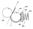
図2は、塗布ローラ1001、カウンターローラ1002および液体保持部材2001などの配置の詳細を示す縦断側面図である。
カウンターローラ1002は、ばねなどを有して構成される不図示の付勢機構によって塗布ローラ1001の周面に向けて付勢されている。この状態で塗布ローラ1001を図中、時計方向に回転させることにより、両ローラの間に塗布液を塗布すべ記録媒体Pを挟持し得ると共に、記録媒体Pを図中の矢印方向に搬送し得るようになっている。
FIG. 2 is a longitudinal side view showing details of the arrangement of the
The
本実施形態では、塗布ローラ1001の材質はゴム硬度30度のEPDMとし、表面粗さはRa1.6μmとし、直径22.19mmとした。カウンターローラ1002の材質はアルミニウムとし、表面は鏡面状に加工し、直径は22.19mmである。
In this embodiment, the material of the
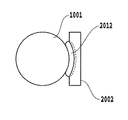
また、液体保持部材2001は、空間形成基材2002と当接部材2009とを有して構成され、ばね2006の付勢力によって塗布ローラ1001の周面に対して付勢されて当接する。そして、この当接により、塗布ローラ1001による液体塗布領域全体に亘って(図2の紙面に垂直な方向に)延在する長尺な液体保持空間Sが形成される。この液体保持空間S内には、後述の液体流路3000から液体保持部材2001の供給口を介して塗布液が供給される。この際、液体保持部材2001が以下のように構成されているため、塗布ローラ1001の停止状態において、液体保持空間Sから外へ不用意に塗布液が漏出するのを防止することができる。
The
この液体保持部材2100の構成を、図3ないし図8に示す。
図3に示すように、液体保持部材2001は、空間形成基材2002と、この空間形成基材2002の一方の面に設けられた環状の当接部材2009とを有して構成されている。空間形成基材2002には、その中央部分における長手方向に沿って、底部の断面形が円弧状をなす凹部2003が形成される。そして、当接部材2009は、その直線部分がこの凹部2003の上縁部に沿って固着され、また、円周部分が上記上縁部から底部を経て反対側の上縁部に至るように固着される。これにより、液体保持部材2001の当接部2009が塗布ローラ1001に当接したとき、塗布ローラの周面形状に沿った当接が可能となり、均一な圧力の当接を実現することができる。
The configuration of the liquid holding member 2100 is shown in FIGS.
As illustrated in FIG. 3, the
本実施形態では、当接部材2009の材質はNBR(ニトリルブタジエンラバー)であり、硬度は共に70度、直径は3.5mmである。
In this embodiment, the material of the
上記のようにこの実施形態における液体保持部材は、継ぎ目のない一体に形成された当接部材2009が、バネ部材2006の付勢力によって塗布ローラ1001の外周面に隙間なく連続した状態で当接する。その結果、液体保持空間Sは、この当接部材2009と、空間形成基材の一面と、塗布ローラ1001の外周面とによる実質的に閉塞した空間となり、この空間に塗布液が保持される。そして、塗布ローラ1001の回転が停止した状態では、当接部材2009と塗布ローラ1001の外周面とは液密状態を維持し、液体が外部へと漏出するのを確実に防止することができる。一方、塗布ローラ1001が回転するときは、後述されるように、塗布液は塗布ローラ1001の外周面と当接部材2009との間をすり抜けて、塗布ローラの外周面に層状に付着する。ここで、塗布ローラ1001の停止状態において、その外周面と当接部材2009とが密接状態にあるとは、上記のとおり、上記液体保持空間Sの内と外との間で液体を通さないことである。この場合、当接部材2009の当接状態としては、それが塗布ローラ1001の外周面に対し、直に接する状態の他、毛管力によって形成される液体の膜を解して上記外周面に当接する状態を含むものである。
As described above, in the liquid holding member in this embodiment, the abutting
また、当接部材2009の長手方向における左右両側部は、正面(図3)、平面(図6)および側面(図7、図8)のいずれの方向から見ても緩やかに湾曲する形状をなしている。このため、塗布ローラ1001に対し、比較的強い押圧力で当接部材2120を当接させても、当接部材2009の全体が略均一に弾性変形し、局所的に大きな歪みが生じることはない。このため、当接部材2009は図6ないし図8に示すように、隙間なく連続的に塗布ローラ1001の外周面に当接し、上記の実質的に閉塞した空間を形成することができる。
Further, the left and right side portions in the longitudinal direction of the abutting
一方、空間形成基材2002には、図3ないし図5に示すように、当接部材2009に囲繞された領域内に、それぞれ空間形成基材2002を貫通する孔を有して構成される液体供給口2004および液体回収口2005が設けられている。これらは空間形成基材の背面側に突設された円筒状の連結部20041,20051にそれぞれ連通している。また、この連結部20041,20051は、後述の液体供給流路3000に連結されている。なお、この実施形態では、液体供給口2004が当接部材2009に囲繞された領域の一端部(図3では左端部)近傍に形成され、液体回収口2005が同領域の他端部(図3では右端部)近傍に設けられる。この液体供給口2004は、液体流路3000から供給される塗布液を前述の液体保持空間Sに供給し、液体回収口2005は液体保持空間S内の液体を液体流路3000へと流出させるためのものである。この液体の供給、流出を行うことにより、液体保持空間S内において、塗布液は上記の左端部から右端部へと流動する。
On the other hand, as shown in FIGS. 3 to 5, the space-forming
塗布液流路
図11は、塗布液供給機構の液体保持部材2001に連結される液体流路3000の概略構成を示す説明図である。
この液体流路3000は、液体保持部材2001を構成する空間形成基材2002の液体供給口2004と塗布液を貯蔵する貯蔵タンク3003とを連結する第1流路(供給流路)3001を有する。また、液体流路3000、は空間形成基材2002の液体回収口2005と貯蔵タンク3003とを連結する第2流路(回収流路)3002を有する。この貯蔵タンク3003には、大気連通口3004が設けられており、また、この大気連通口には、大気との連通、遮断を切換える大気連通弁3005が設けられている。また、第1流路3001内には切換弁3006が設けられており、この切換弁3006によって第1流路3001と大気との連通、遮断が切換え可能となっている。さらに第2流路3002内には、本液体流路3000内で塗布液および空気を所望の方向へと強制的に流動させるためのポンプ3007が連結されている。
The coating liquid flow path 11 is an explanatory diagram showing a schematic configuration of the liquid flow path 3000 to be coupled to the
The liquid flow path 3000 includes a first flow path (supply flow path) 3001 that connects the
この実施形態において、第1流路3001および第2の流路3002は円管状のチューブによって形成されている。それぞれのチューブの端部に形成される開口部は、貯蔵タンク3003の底部もしくは底部に近い位置に配置され、貯蔵タンク3003内の塗布液を完全に消費し得るようになっている。
In this embodiment, the
また、本実施形態の切換弁3006は、第1流路3001と大気との連通、遮断を切換え得るものであれば、種々のものが適用可能であるが、ここでは、図11に示すような三方弁を使用している。この三方弁3006は、互いに連通する3つのポートを有する。そして、このポートのうち2つのポートを、第1流路3001における貯蔵タンク側チューブ3011と、液体保持部材側チューブ3012と、大気連通口3013の中のいずれか二つに選択的に連通させることができる。そして、この三方弁3006の切換えにより、チューブ3011とチューブ3012とを連通させる連結状態と、チューブ3012と大気連通口3013とを連通させる連結状態とが選択的に切り換えることができる。これにより、液体保持部材2001と塗布ローラ1001とによって形成される空間Sに対し、貯蔵タンク3003内の塗布液あるいは大気連通口3013から取り込まれる空気の何れかを選択して供給することが可能となる。なお、三方弁3006の切換えは、後述の制御部4000からの制御信号によって行われ、塗布液の充填、供給などが行われる。
制御系
図12は、本実施形態の液体塗布装置における制御系の概略構成を示すブロック図である。
図において、4000は液体塗布装置全体を制御する制御部を示す。この制御部4000は、種々の演算、制御、判別などの処理動作を実行するCPU4001を有する。また、このCPU4001によって実行される、図13〜図15にて後述される処理などの制御プログラムなどを格納するROM4002と、CPU4001の処理動作中のデータや入力データなどを一時的に格納するRAM4003を有する。さらに、電源OFF時にフラグの内容を保持するEEPROM4012などを有する。後述する終了工程が完了されたか否かを示す情報フラグ(終了工程フラグ)はこのEEPROM4012に記憶される。
Control system Figure 12 is a block diagram showing a schematic configuration of a control system in the liquid application apparatus of the present embodiment.
In the figure,
この制御部4000には、所定の指令あるいはデータなどを入力するキーボードあるいは各種スイッチなどを含む入力操作部4004、液体塗布装置の入力・設定状態などをはじめとする種々の表示を行う表示部4005、塗布媒体の位置や各部の動作状態などを検出するセンサなどを含む検出部4006、前記ローラ駆動モータ1004、ポンプ駆動モータ4009、大気連通弁3005および切換弁3006などがそれぞれ駆動回路4007,4008,4010,4011を介して接続されている。
The
液体塗布動作シーケンス
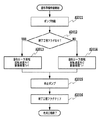
図13は、本実施形態の液体塗布装置の液体塗布に係わる処理手順を示すフローチャートである。以下、このフローチャートを参照して、液体塗布にかかる各工程を説明する。すなわち、液体塗布装置に電源が投入されると、制御部4000は、図13に示すフローチャートに従って以下の塗布動作シーケンスを実行する。
Liquid Application Operation Sequence FIG. 13 is a flowchart showing a processing procedure related to liquid application of the liquid application apparatus of this embodiment. Hereinafter, with reference to this flowchart, each process concerning liquid application will be described. That is, when power is turned on to the liquid coating apparatus, the
〔充填工程〕
ステップS1では、保持空間Sに対する塗布液の充填工程を実行する。
[Filling process]
In step S1, a coating liquid filling step for the holding space S is executed.
図14は、この充填工程の詳細な処理を示すフローチャートである。図14において、まず、大気連通弁3005を開放し、貯蔵タンク3003を大気に開放させる(ステップS101)。
FIG. 14 is a flowchart showing detailed processing of this filling step. In FIG. 14, first, the
次に、終了工程フラグを参照して終了工程フラグが立てられているか否かを判断する(ステップS102)。すなわち、この終了工程フラグは、図13のステップS10、S11で後述されるように、図11に示した液体保持空間Sおよび液体流路3001、3002から塗布液を回収して貯蔵タンク3003に戻す動作を含む終了工程を実行したときに立てられるものである。従って、終了工程フラグが記憶されて(立てられて)いるときは、前回の電源オフ時に塗布液の回収動作が正常に行われていると判断する。一方、終了工程フラグが立てられていないときは、回収動作が行われずに電源がオフされたと判断する。なお、回復動作が行われず電源がオフになる例として、例えば、停電などによって装置の動作が意図せずして停止する場合などが考えられる。
Next, it is determined whether or not the end process flag is set with reference to the end process flag (step S102). That is, the end process flag collects the coating liquid from the liquid holding space S and the
そして、次に、充填動作を行うが、回収動作が行われている場合は、通常の充填動作を行う。すなわち、図11に示した液体流路において、ポンプ3007を回転速度Rp1で規定時間Tp1の間作動する(ステップS103)。これにより、液体保持空間Sおよび各流路3001,3002内にポンプによって内部の空気が貯留部へと送られて大気へと排出されると共に各部に塗布液が充填される。
Next, a filling operation is performed. When a collecting operation is performed, a normal filling operation is performed. That is, in the liquid flow path shown in FIG. 11, the
一方、終了工程フラグが記憶されていないと判断したときは、回収動作を正常に実行しておらず、液体保持部材や液体流路に増粘ないし固着した塗布液が存在する可能性がある。このため、ステップS104で、回復動作を兼ねた充填動作として、ステップS103で行われる通常の充填動作よりもより強い流動を生じさせる充填を行う。すなわち、ポンプ3007を回転速度Rp1で、上記の規定時間Tp1より長い規定時間Tp2の間作動する。ここで、規定時間Tp2は、液体保持空間Sおよび各液体流路3001,3002内に残存する増粘ないし固着した液体を再流動させるのに十分な時間である。これにより、液体保持空間および各液体流路に存在した増粘などした塗布液は循環に差し支えない程度に再流動化され、正常な塗布液の充填が行われる。この回復動作を兼ねた充填動作によって、塗布ローラ1001に対し塗布液が供給可能な状態となる。
On the other hand, when it is determined that the end process flag is not stored, there is a possibility that the collecting operation is not normally executed, and there is a coating liquid that thickens or adheres to the liquid holding member or the liquid channel. For this reason, in step S104, as a filling operation that also serves as a recovery operation, filling that causes a stronger flow than the normal filling operation performed in step S103 is performed. That is, the
なお、回復を兼ねた充填では、通常の充填動作を比べて、充填する時間を長くするのではなく、後述の実施形態で説明されるようにポンプの回転速度を増してもよく、あるいは、これらの時間と回転速度の両方を増すようにしても良いことはもちろんである。 In addition, in filling that also serves as a recovery, the rotation time of the pump may be increased as described in the embodiments described later, rather than increasing the filling time as compared with the normal filling operation, or these Of course, both the time and the rotation speed may be increased.
また、上述のように、前回の電源オフ時に正常に回収動作が行われている場合は、ステップS103で行われるのは、充填動作としての液体流動であり、一方、ステップS104で行われるのは、回復動作を兼ねた充填動作である。このように、ステップS104では、先ず、所定の回復動作を行い、次に、ステップS103と同じ充填動作を行うようにしてもよい。この場合、上記のようにポンプ駆動の規定時間を異ならせる場合は、規定時間の長い分を回復動作とみなすこともできる。 Further, as described above, when the recovery operation is normally performed when the power is turned off last time, the liquid flow as the filling operation is performed in step S103, whereas the operation performed in step S104 is performed. The filling operation also serves as a recovery operation. Thus, in step S104, first, a predetermined recovery operation may be performed, and then the same filling operation as in step S103 may be performed. In this case, when the specified time for driving the pump is varied as described above, the longer specified time can be regarded as the recovery operation.
〔塗布準備動作〕
再び図13を参照する。前述した図14に示される充填動作を終了すると(ステップS1)、塗布準備動作を行う(ステップS2)。
[Preparation operation]
Refer to FIG. 13 again. When the filling operation shown in FIG. 14 is completed (step S1), a coating preparation operation is performed (step S2).
図15は、この塗布準備動作工程の詳細を示すフローチャートである。図15において、先ず、図11に示した流路におけるポンプ3007を作動させる(ステップS201)。次に、ステップS1の処理と同様、終了工程フラグを参照する(ステップS202)。
FIG. 15 is a flowchart showing details of the coating preparation operation process. In FIG. 15, first, the
ここで、終了工程フラグが記憶されているときは、前回の電源オフに際して塗布液が正常に回収されていると判断する。すなわち、液体保持空間S内で塗布ローラの表面に付着した塗布液は微量であると判断する。この場合は、塗布ローラ1001を回転速度Rr1で規定時間Tr1の間回転させる(ステップ203)。
Here, when the end process flag is stored, it is determined that the coating liquid has been normally recovered when the power is turned off the last time. That is, it is determined that the amount of coating liquid adhering to the surface of the coating roller in the liquid holding space S is very small. In this case, the
一方、終了工程フラグが記憶されていないときは、終了工程は正常に実行されていないと判断する。この場合、液体保持空間Sを形成する塗布ローラ表面上には塗布液が付着しままであり、その塗布液は増粘している可能性がある。 On the other hand, when the end process flag is not stored, it is determined that the end process is not normally executed. In this case, there is a possibility that the coating liquid has adhered to the surface of the coating roller forming the liquid holding space S, and the coating liquid may be thickened.
そこで、塗布ローラ1001を回転速度Rr1で、上記の規定時間Tr1より長い規定時間Tr2の間回転させる(ステップ204)。ここで、このとき規定時間Tr2は、塗布ローラ1001の表面に付着する増粘インクが当接部材2009によってかき取られる、もしくは正常な塗布液により再流動化されるのに十分な時間である。これにより、塗布ローラ表面は正常な状態となる。このように塗布ローラの回転は、塗布ローラの回復動作に該当する。
Therefore, the
なお、ステップS1の充填工程における充填動作の際に塗布ローラを回転させることによって、塗布ローラに付着した増粘した塗布液を除くことも可能ではある。しかし、本実施形態では、この除去を確実に行うべく、上述のように、回復動作を含む準備動作を行う。 ローラの回転を終了すると、ポンプを停止し(ステップS205)、EEPROMに終了工程フラグが記憶されていればクリアされる(ステップS206)。 In addition, it is also possible to remove the thickened coating liquid adhering to the coating roller by rotating the coating roller during the filling operation in the filling process of Step S1. However, in the present embodiment, as described above, the preparatory operation including the recovery operation is performed in order to reliably perform this removal. When the rotation of the roller is completed, the pump is stopped (step S205), and if the end process flag is stored in the EEPROM, it is cleared (step S206).
〔塗布動作〕
再び図13を参照すると、塗布開始命令があれば塗布動作を開始する(ステップS3)。塗布動作が開始されると最初にポンプが作動する(ステップS4)。また、塗布ローラ1001が図1の矢印に示すように、時計周りに回転を開始する(ステップS5)。この塗布ローラ1001の回転により、液体保持空間Sに充填された塗布液Lは、塗布ローラ1001に対する液体保持部材2001の当接部材2009の押圧力に抗して、塗布ローラ1001と当接部材2009の下縁部2011との間を摺り抜ける。そして、塗布ローラ1001の外周に層状態となって付着する。塗布ローラ1001に付着した塗布液Lは、塗布ローラ1001とカウンターローラ1002との当接部に送られる。
(Application operation)
Referring to FIG. 13 again, if there is a coating start command, the coating operation is started (step S3). When the application operation is started, the pump is first activated (step S4). Further, the
次いで、塗布媒体送給機構1006によって塗布ローラ1001とカウンターローラ1002との間に塗布媒体が搬送され、これらのローラの間に塗布媒体が挿入される。これとともに、塗布ローラ1001とカウンターローラ1002の回転に伴い排紙部へ向けて搬送される(ステップS6)。この搬送の間に、塗布ローラ1001の外周面に塗布された塗布液が、図9に示すように塗布ローラ1001から塗布媒体Pに転写される。なお、塗布ローラ1001とカウンターローラ1002との間に塗布媒体を供給する機構としては、上記の送給機構に限られないことは勿論である。例えば、所定のガイド部材を補助的に用いる手差しによる機構を併せて用いてもよく、また、手差し機構を単独で用いる構成など、どのような機構を用いてもよい。
Next, the application
図9において、交差する斜線で表現した部分が塗布液Lを示している。なお、ここでは、塗布ローラ1001および塗布媒体Pにおける塗布液の層の厚みは、塗布時における塗布液Lの様子を明確に図示する上で、実際の厚みよりもかなり過大に表している。
In FIG. 9, a portion expressed by crossing oblique lines indicates the coating liquid L. Here, the thickness of the coating liquid layer on the
上記のようにして、塗布媒体Pの塗布された部分は塗布ローラ2001の搬送力により矢印方向に搬送される。これとともに、塗布媒体Pと塗布ローラ2001の接触部に塗布媒体Pの未塗布部分が搬送され、この動作を連続もしくは間欠的に行うことで塗布媒体全体に塗布液を塗布して行く。
As described above, the coated portion of the coating medium P is transported in the arrow direction by the transport force of the
ところで、図9においては、当接部材2009からすり抜けて塗布ローラ2001に付着した塗布液Lの全てが塗布媒体Pに転写された理想的な塗布状態を示している。しかし、実際には、塗布ローラ1001に付着した塗布液Lの全てが塗布媒体Pに転写されるとは限らない。つまり、搬送される塗布媒体Pが塗布ローラ1001から離間する際、塗布液Lは、塗布ローラ1001にも付着し、塗布ローラ1001に塗布液Lが残留することが多い。この塗布ローラ1001における塗布液Lの残留量は、塗布媒体Pの材質及び表面の微小な凹凸の状態によっても異なるが、塗布媒体Pが普通紙の場合、塗布動作後も塗布ローラ1001の周面には塗布液Lが残留する。
Incidentally, FIG. 9 shows an ideal application state in which all of the application liquid L that has passed through the
図20,図21,図22は、媒体Pが普通紙である場合における媒体の表面と塗布面での塗布過程を説明する説明図である。本図では液体を黒く塗りつぶしてある。 20, FIG. 21, and FIG. 22 are explanatory diagrams for explaining the coating process on the surface and coating surface of the medium when the medium P is plain paper. In this figure, the liquid is painted black.
図20は塗布ローラ1001とカウンタローラ1002とのニップ部より上流側での状態を示している。同図において塗布ローラ1001の塗布面には液体が塗布面の表面の微細な凹凸をわずかに被うように液体が付着している。
FIG. 20 shows a state upstream of the nip portion between the
図21は塗布ローラ1001とカウンタローラ1002とのニップ部での、媒体Pである普通紙の表面と塗布ローラ1001の塗布面の状態を示している。同図において媒体Pである普通紙の表面の凸部は塗布ローラ1001の塗布面と接触し、接触した部分より液体が瞬時に媒体Pである普通紙の表面の繊維に浸透ないし吸着する。また塗布ローラ1001の塗布面には普通紙の表面の凸部と接触しない部分に付着した液体が残留される。
FIG. 21 shows the state of the surface of plain paper as the medium P and the application surface of the
図22は塗布ローラ1001とカウンタローラ1002とのニップ部より下流側での状態を示している。同図は媒体と塗布ローラ1001の塗布面が完全に離脱した状態である。塗布ローラ1001の塗布面には普通紙の表面の凸部と接触しない部分に残留した液体と接触部における液体も極微量ながら塗布面に残留する。
FIG. 22 shows a state downstream of the nip portion between the
この塗布ローラ1001に残留した塗布液は、塗布ローラ1001に対する液体保持部材2001の当接部材2009の押圧力に抗して、塗布ローラ1001と当接部材2009の上縁部2010との間をすり抜けて液体保持空間S内に戻る。そして、同空間S内に充填されている塗布液と混合される。
The application liquid remaining on the
また、この塗布液の戻し動作は、図10に示すように塗布媒体が存在しない状態で塗布ローラ1001を回転させた場合にも同様に行われる。すなわち、塗布ローラ1001を回転することで塗布ローラ1001の外周に付着した塗布液は、カウンターローラ1002と当接する部分(ニップ部)の間をすり抜ける。すり抜けた後は塗布ローラ1001側とカウンターローラ1002側とに塗布液が分離し、塗布ローラ1001に塗布液が残留する。そして、塗布ローラ1001側に付着した塗布液Lは当接部材2009の上縁部2010と塗布ローラ1001との間をすり抜けて液体保持空間S内に侵入し、同空間S内に充填されている塗布液に混合する。
Further, the returning operation of the coating liquid is performed in the same manner when the
〔終了工程〕
上記のようにして、塗布媒体への塗布動作が実行されると、次に塗布工程を終了して良いか否かの判断を行い(ステップS7)、塗布工程を終了しない場合は、ステップS6に戻り、塗布媒体の塗布が必要な部分全体に塗布工程を終了するまで塗布動作を繰り返す。塗布工程を終了すると、塗布ローラ1001を停止させ(ステップS8)、さらに、ポンプ3007の駆動を停止させる(ステップS9)。この後、ステップS2へ移行し、塗布開始指令が入力されていれば、前述のステップS2〜S9の動作を繰り返す。塗布開始指令が入力されていなければ、保持空間Sおよび液体流路内の塗布液を回収する回収動作などの後処理を行い(ステップ10)、塗布にかかる処理を終了する。ステップ10の後処理終了後、EEPROM4012に終了工程フラグを記憶させる(ステップ11)。
[End process]
As described above, when the application operation to the application medium is executed, it is determined whether or not the application process can be completed next (step S7). If the application process is not ended, the process proceeds to step S6. Returning, the coating operation is repeated until the coating process is completed on the entire portion where coating of the coating medium is required. When the coating process is finished, the
なお、上記回収動作(ステップ10)は、前記大気連通弁3005および切換弁3006を開放し、ポンプ3007を駆動することによって塗布液を塗布液保持空間Sおよび第2流路3002内の塗布液を液体貯留タンク3003へと流入させることによって行う。この回収動作を行うことにより、液体保持空間Sからの塗布液の蒸発を抑制することができる。また、回収動作後は大気連通弁3005を閉じ、切換弁3006を切換えて第1流路3001および大気連通口3013との連通を遮断することにより、貯蔵タンク3003を大気から遮断する。これにより、液体貯蔵タンク3003からの塗布液の蒸発を抑制することができると共に、移動、運搬などにおいて装置の姿勢が傾いた場合にも塗布液が外部へ流出するのを完全に防止することができる。
In the recovery operation (step 10), the
以上のように、この実施形態では、異常終了状態などにより液体保持空間Sや液体流路に塗布液が保持されたままであっても、塗布開始前に塗布液の回収又は未回収の判定を行う。そして、その判定結果に基づいて、塗布液の増粘、固着を解消させる回復動作を実行している。これにより、その後の塗布動作を良好に行うことができる。 As described above, in this embodiment, even when the coating liquid is held in the liquid holding space S or the liquid flow path due to an abnormal end state or the like, it is determined whether the coating liquid is recovered or not recovered before starting the application. . Then, based on the determination result, a recovery operation for eliminating the thickening and sticking of the coating liquid is performed. Thereby, subsequent application | coating operation | movement can be performed favorably.
(第2実施形態)
本発明の第2実施形態は、終了工程が行われていないと判断した場合に、充填工程でポンプ作動速度を速くし、また、塗布ローラの塗布準備動作おいて塗布ローラの駆動速度を速くするものである。図16および図17は、それぞれ充填動作および塗布準備動作の詳細を示すフローチャートである。これらの動作以外は上述した第1実施形態と同様である。
(Second Embodiment)
In the second embodiment of the present invention, when it is determined that the end process is not performed, the pump operation speed is increased in the filling process, and the application roller driving speed is increased in the application preparation operation of the application roller. Is. 16 and 17 are flowcharts showing details of the filling operation and the application preparing operation, respectively. Other than these operations, the second embodiment is the same as the first embodiment.
〔充填工程〕
図16において、最初に、大気連通弁3005を開放し、貯蔵タンク3003を大気に開放させる(ステップS1011)。次に、終了工程フラグを参照しフラグが記憶されて(立てられて)いるか否かを判断する(ステップS1012)。終了工程フラグが記憶されていれば、前回の電源オフ時に塗布液の回収動作がされているとして、ポンプ3007を回転速度Rp1で規定時間Tp1の間作動する(ステップS1013)。これにより、液体保持空間Sおよび各流路3001,3002内にポンプによって内部の空気が貯留部へと送られて大気へと排出されると共に各部に塗布液が充填される。
[Filling process]
In FIG. 16, first, the
一方、終了工程フラグが記憶されていないときは、前回の電源オフ時に終了工程が正常に実行されておらず、液体保持部材や液体流路に増粘などした塗布液が存在する可能性があるとして、ポンプ3007を上記の正常終了時の回転速度Rp1より大きな回転速度Rp2で、規定時間Tp1の間作動させる(ステップS1014)。ここで、回転速度Rp2は、液体保持空間Sおよび液体流路3001,3002内に残存する増粘などした液体を再流動化させるのに十分な回転速度である。これにより、液体保持空間Sおよび各液体流路に存在した増粘などした塗布液は循環に差し支えない程度に再流動化され、塗布液の充填が良好になされる。この初期動作によって、塗布ローラ1001に対し塗布液が供給可能な状態となる。
On the other hand, when the end process flag is not stored, the end process is not normally executed when the power is turned off last time, and there is a possibility that there is a coating liquid with increased viscosity in the liquid holding member or the liquid channel. As described above, the
〔塗布準備動作〕
次に、図17に示す塗布準備動作では、先ず、ポンプを作動させる(ステップS2011)。次に、終了工程フラグを参照してこのフラグが記憶されているか否かを判断する(ステップS2012)。終了工程フラグが記憶されているときは、塗布液の回収動作が正常に行われており、塗布ローラ表面に付着した塗布液は微量であるとして、塗布ローラ1001を回転速度Rr1で規定時間Tr1の間回転させる(ステップ2013)。
[Preparation operation]
Next, in the coating preparation operation shown in FIG. 17, first, the pump is operated (step S2011). Next, it is determined whether or not this flag is stored with reference to the end process flag (step S2012). When the end process flag is stored, it is assumed that the operation of collecting the coating liquid is normally performed and that the amount of the coating liquid adhering to the surface of the coating roller is very small. (Step 2013).
一方、終了工程フラグが記憶されていないときは、回収動作が正常に行われないで電源がオフとされたと判断する。この場合は、液体保持空間Sを形成する塗布ローラ表面には増粘した塗布液が付着していると判断し、塗布ローラ1001を上記回転速度Rr1より大きな回転速度Rr2で、規定時間Tr1の間回転させる(ステップ2014)。ここで、回転速度Rr2は、塗布ローラ1001の表面に付着する増粘インクが当接部材2009によってかき取られるか、もしくは正常な塗布液により再流動化されるのに十分な速度である。これにより、塗布ローラ表面は正常な状態となる。
On the other hand, when the end process flag is not stored, it is determined that the collection operation is not normally performed and the power is turned off. In this case, it is determined that the thickened coating liquid is attached to the surface of the coating roller forming the liquid holding space S, and the
なお、図17に示すステップS2014の塗布ローラの回転速度を増す準備動作は、図16に示す充填動作によって塗布ローラから増粘した塗布液が十分に除去できる場合には実行する必要がないことは、第1実施形態と同様である。 It should be noted that the preparation operation for increasing the rotation speed of the application roller in step S2014 shown in FIG. 17 is not necessarily performed when the application liquid thickened from the application roller by the filling operation shown in FIG. 16 can be sufficiently removed. This is the same as in the first embodiment.
塗布ローラの回転を終了すると、ポンプを停止し(ステップS2015)、次に、EEPROMに終了工程フラグが記憶されているときはクリアする(ステップS2016)。 When the rotation of the application roller is finished, the pump is stopped (step S2015), and then, when an end process flag is stored in the EEPROM, it is cleared (step S2016).
以上のように、本実施形態でも第1実施形態と同様、異常終了状態などにより液体保持空間Sや液体流路に液体が保持されたままで次の塗布動作が開始される場合でも、塗布開始前に塗布液の回収または未回収の判定を行い、塗布液の増粘、固着を解消する回復動作を行うことができる。その結果、それに続く塗布動作を良好に行うことができる。 As described above, in the present embodiment as well as in the first embodiment, even when the next application operation is started while the liquid is held in the liquid holding space S or the liquid flow path due to an abnormal end state or the like, before the start of application. Then, it is possible to determine whether the coating liquid is recovered or not recovered, and to perform a recovery operation for eliminating the thickening and sticking of the coating liquid. As a result, the subsequent coating operation can be performed satisfactorily.
(第3実施形態)
本発明の第3実施形態は、前回の電源オフ時に回収動作が行われていない場合に、充填動作および塗布ローラの塗布準備動作で、ポンプおよび塗布ローラそれぞれの駆動回数を多くし、未回収で増粘した可能性のある塗布液を再流動化させるものである。
(Third embodiment)
In the third embodiment of the present invention, when the collecting operation is not performed when the power is turned off last time, the number of times of driving the pump and the applying roller is increased in the filling operation and the applying roller applying preparation operation. The coating liquid that may have increased in viscosity is reflowed.
図18および図19は、本実施形態に係るそれぞれ充填動作および塗布準備動作の詳細を示すフローチャートである。これらの動作以外は第1実施形態と同様である。 18 and 19 are flowcharts showing details of the filling operation and the application preparing operation according to the present embodiment, respectively. Except for these operations, the second embodiment is the same as the first embodiment.
〔充填工程〕
図18において、先ず、貯蔵タンク3003の大気連通弁3005を大気に開放させる(ステップS1021)。次に、終了工程フラグを参照し(ステップS1022)、終了工程フラグが記憶されていれば、塗布液が正常に回収されているとして、ポンプ3007を通常の充填動作として、回転速度Rp1で規定時間Tp1の間作動する動作を1回行う(ステップS1023)。
[Filling process]
In FIG. 18, first, the
一方、終了工程フラグが記憶されていないときは、前回の終了工程を正常に終えておらず、液体保持部材または液体流路に増粘などした塗布液が存在すると判断して、ポンプ3007を回転速度Rp1で規定時間Tp1の間駆動するポンプ動作を、通常の充填動作に回復動作分を加えた、N回(N>1)行う(ステップS1024)。ここで、動作回数Nは、液体保持空間Sや液体流路3001,3002内に残存する増粘などした液体を再流動化させるのに十分な回数に設定される。これにより、液体保持空間Sおよび各液体流路に存在した増粘などした塗布液は循環に差し支えない程度に再流動化され、正常な塗布液の充填が行われる。この初期動作によって、塗布ローラ1001に対し塗布液が供給可能な状態となる。
On the other hand, when the end process flag is not stored, it is determined that the previous end process has not been completed normally, and there is a coating liquid with increased viscosity in the liquid holding member or the liquid flow path, and the
〔塗布準備動作〕
図19に示す塗布準備動作では、先ず、ポンプを作動させる(ステップS2021)。次に、終了工程フラグを参照する(ステップS2022)。終了工程フラグが記憶されているときは、前回の電源オフ時に塗布液の回収動作が正常に行われており、塗布ローラ表面に付着した塗布液は微量であるとして、塗布ローラ1001を通常の準備動作の回転速度Rr1で規定時間Tr1の間回転する動作を1回行う(ステップ2023)。
[Preparation operation]
In the application preparation operation shown in FIG. 19, first, the pump is operated (step S2021). Next, the end process flag is referred to (step S2022). When the end process flag is stored, it is assumed that the application liquid is recovered normally when the power is turned off last time, and that the application liquid attached to the application roller surface is very small. The operation of rotating at the rotational speed Rr1 for the specified time Tr1 is performed once (step 2023).
一方、終了工程フラグが記憶されていないときは、回収動作が正常に行われていないと判断する。この場合は、液体保持空間Sを形成する塗布ローラ表面には塗布液が付着しているとして、塗布ローラ1001を回転速度Rr1で規定時間Tr1の回転動作を、通常の準備動作に回復動作分を加えたM回(M>1)行う(ステップ2014)。このとき動作回数M回は、塗布ローラ1001の表面に付着する増粘インクが当接部材2009によってかき取られる、もしくは正常な塗布液により再流動化するのに十分な回数である。これにより、塗布ローラ表面は正常な状態となる。
On the other hand, when the end process flag is not stored, it is determined that the collecting operation is not normally performed. In this case, assuming that the coating liquid adheres to the surface of the coating roller forming the liquid holding space S, the rotation operation of the
ローラ回転を終了すると、ポンプを停止し(ステップS2025)、EEPROMに終了工程フラグが記憶されていればクリアする(ステップS2026)。 When the roller rotation is finished, the pump is stopped (step S2025), and if the end process flag is stored in the EEPROM, it is cleared (step S2026).
なお、図19に示すステップS2024の塗布ローラの回転動作の回数を増す準備動作は、図18に示す充填動作によって塗布ローラから増粘した塗布液が十分に除去できる場合には実行する必要がないことは、第1および第2実施形態と同様である。 The preparation operation for increasing the number of rotations of the application roller in step S2024 shown in FIG. 19 does not need to be performed when the coating liquid thickened from the application roller by the filling operation shown in FIG. 18 can be sufficiently removed. This is the same as in the first and second embodiments.
以上のように、本実施形態でも、異常終了状態などにより液体保持空間Sおよび流路に液体が保持されたままであっても、塗布開始前に塗布液の回収または未回収の判定を行い、増粘などした塗布液を再流動化させる回復動作を行うことができる。 As described above, even in the present embodiment, even when the liquid holding space S and the flow path are retained due to an abnormal end state or the like, it is determined whether the coating liquid has been collected or not collected before the start of coating. A recovery operation can be performed to reflow the viscous coating liquid.
(第4実施形態)
上述した第1ないし第3の実施形態は、用紙に塗布液を塗布する塗布装置に関して説明したが、本発明の第4の実施形態は、以上説明した塗布装置を塗布機構として備えたインクジェット記録装置に関するものである。本実施形態の記録装置は、概略、その塗布機構は上述した塗布装置と同様のものである。そして、図13に示した充填動作(ステップS1)と回転準備動作(ステップS2)と同様の動作を行う。以下では、主に上述した塗布装置と異なる点を説明する。
(Fourth embodiment)
The first to third embodiments described above have been described with reference to a coating apparatus that applies a coating liquid to paper. However, the fourth embodiment of the present invention is an inkjet recording apparatus that includes the above-described coating apparatus as a coating mechanism. It is about. The recording apparatus of the present embodiment is roughly the same as the application apparatus described above in its application mechanism. Then, operations similar to the filling operation (step S1) and the rotation preparation operation (step S2) shown in FIG. 13 are performed. Below, a different point from the coating device mentioned above is mainly demonstrated.
図23は、本発明のインクジェット記録装置の一実施形態であるインクジェットプリンタの概略構成を示す図である。本実施形態のインクジェットプリンタは、記録用紙などの記録媒体に液体を塗布する液体塗布機構を備えたものである。 FIG. 23 is a diagram showing a schematic configuration of an ink jet printer which is an embodiment of the ink jet recording apparatus of the present invention. The ink jet printer of this embodiment includes a liquid application mechanism that applies liquid to a recording medium such as recording paper.
このインクジェット記録装置1には、複数枚の記録媒体Pを積載する給送トレイ2が設けられており、その断面が半月形状の分離ローラ3が、給送トレイ2に積載された記録媒体Pを1枚ずつ分離して搬送経路に給送する。搬送経路中には、液体塗布機構における塗布部材を構成する塗布ローラ1001とこれに塗布液を供給する液体保持部材2001、および塗布ローラ1001とともに記録媒体を挟んで搬送するためのカウンターローラ1002が配置されている。塗布ローラ1001はローラ駆動モータの回転によって図23において時計周り方向に回転し、記録媒体Pを図中上向に搬送しながら、記録媒体Pの必要な部分に塗布液を塗布する。記録媒体に対して塗布液が均一に塗布できるように、塗布ローラ1001の表面は実質的に凹凸の無い面で構成されている。塗布液が塗布された記録媒体Pは、搬送ローラ4とピンチローラ5との間に送られるとともに、搬送ローラ4が、図中、反時計周り方向へと回転駆動されることによって、記録媒体Pはプラテン6の上を搬送される。
The ink jet recording apparatus 1 is provided with a feeding
このプラテン6上を搬送される記録媒体Pに対して、記録ヘッド7に対向する位置で記録が行われる。すなわち、記録ヘッド7は所定数のインク吐出用のノズルを配設したインクジェット記録ヘッドであり、この記録ヘッド7が図の紙面と垂直方向に走査する間に、記録データに従ってノズルから記録媒体Pに対してインク滴を吐出して記録を行う。この記録動作と搬送ローラ4による所定量の搬送動作とを交互に繰り返しながら、塗布液が塗布された記録媒体に記録を行って行く。この記録動作とともに、記録媒体Pの搬送路において記録ヘッドの走査領域の後流側に設けられた、排紙ローラ8と拍車9によって排紙トレイ10上に排紙される。
Recording is performed on the recording medium P conveyed on the platen 6 at a position facing the
なお、このインクジェット記録装置としては、インクを吐出するノズルを記録媒体の最大幅に亘って配設した長尺な記録ヘッドを用いて記録動作を行ういわゆるフルライン型のインクジェット記録装置を構成することも可能である。 As the ink jet recording apparatus, a so-called full line type ink jet recording apparatus that performs a recording operation using a long recording head in which nozzles for ejecting ink are arranged over the maximum width of the recording medium is configured. Is also possible.
また、本実施形態で用いる塗布液は、インクの色材である顔料を凝集させる処理液である。具体的な組成は次のとおりである。
硝酸カルシウム・4水和物 10%
グリセリン 42%
界面活性剤 1%
水 残量
The coating liquid used in this embodiment is a treatment liquid that agglomerates pigments that are ink color materials. The specific composition is as follows.
Glycerin 42%
Surfactant 1%
Water remaining
また、この塗布液の粘度は25℃で5〜6cP(センチポアズ)である。なお、本発明の適用において、塗布液は上記のものに限られないことは勿論である。例えば、別の塗布液として、染料を不溶化あるいは凝集させる成分を含有する液体を用いることが可能である。 Moreover, the viscosity of this coating liquid is 5-6 cP (centipoise) at 25 degreeC. Of course, in the application of the present invention, the coating solution is not limited to the above. For example, a liquid containing a component that insolubilizes or aggregates the dye can be used as another coating liquid.
本実施形態では、塗布液として処理液を用いることにより、この処理液とこの処理液が塗布された記録媒体に吐出されるインクの色材である顔料を反応させて顔料の凝集を促進させる。そして、顔料の凝集を促進させることにより、記録濃度の向上を図ることができる。さらに、ブリーディングの軽減または防止することも可能となる。なお、インクジェット記録装置において用いる塗布液としては、上記の例に限られないことはもちろんである。 In this embodiment, by using the treatment liquid as the coating liquid, the pigment, which is the color material of the ink discharged to the recording medium coated with the treatment liquid, is reacted to promote the aggregation of the pigment. The recording density can be improved by promoting the aggregation of the pigment. Furthermore, bleeding can be reduced or prevented. Of course, the coating liquid used in the ink jet recording apparatus is not limited to the above example.
塗布する液体に水を用いる場合、本発明の塗布ローラとの液体保持部材の当接部分での周動性は、表面張力を下げる成分を前記液体に含ませることで良好なものとなる。上述の塗布する液体の成分の一例では、グリセリン及び界面活性剤が水の表面張力を下げる成分である。 When water is used as the liquid to be applied, the peripheral movement at the contact portion of the liquid holding member with the application roller of the present invention is improved by including a component that lowers the surface tension in the liquid. In an example of the liquid component to be applied, glycerin and a surfactant are components that lower the surface tension of water.
制御系
図24は、本実施形態のインクジェットプリンタにおける制御系の概略構成を示すブロック図である。
図に示すように、塗布ローラの駆動機構や液体流路のポンプ駆動や弁の切り替えの機構およびその制御は図12に示した構成と同様である。異なる点として、本実施形態では、CPU5001は、図25にて後述する処理手順のプログラムに従い、塗布機構の各要素の駆動を制御するとともに、記録機構にかかるLFモータ5013、CRモータ5015、および記録ヘッド7の駆動を、それぞれの駆動回路5012、5014、ヘッドドライバ5016を介して制御する。すなわち、LFモータ5013の駆動によって搬送ローラ4などを回転させ、また、CRモータの駆動によって記録ヘッド7を搭載したキャリッジを移動させる。さらに、記録ヘッドのノズルからインクを吐出させる制御を行う。
Control system Figure 24 is a block diagram showing a schematic configuration of a control system in the inkjet printer of this embodiment.
As shown in the figure, the driving mechanism of the application roller, the pump driving of the liquid flow path, the valve switching mechanism, and the control thereof are the same as the configuration shown in FIG. As a difference, in this embodiment, the
図25は、本実施形態のインクジェットプリンタにおける液体塗布およびそれに伴う記録動作の手順を示すフローチャートである。
本プリンタに電源が投入されると、制御部5000は、図25に示すフローチャートに従って以下の塗布動作および記録動作のシーケンスを実行する。
FIG. 25 is a flowchart showing a procedure of liquid application and a recording operation associated therewith in the ink jet printer of the present embodiment.
When the printer is turned on, the
〔充填工程〕
ステップS4001では、液体保持空間Sに対する塗布液の充填を実行する。この充填工程は、図13に示した充填工程(ステップS1)と同じである。すなわち、上述した本発明の各実施形態に係る、終了工程フラグの判断およびそれに基づくポンプ駆動などの充填動作の制御を行う。
[Filling process]
In step S4001, the liquid holding space S is filled with the coating liquid. This filling step is the same as the filling step (step S1) shown in FIG. That is, according to each embodiment of the present invention described above, the determination of the end process flag and the control of the filling operation such as the pump drive based on the determination are performed.
〔回転準備動作〕
充填動作を終了すると、塗布準備動作を行う(ステップS4002)。すなわち、上述した本発明の各実施形態に係る、終了工程フラグの判断およびそれに基づく塗布ローラの回転駆動などの準備動作の制御を行う。
[Rotation preparation operation]
When the filling operation is finished, a coating preparation operation is performed (step S4002). That is, according to each embodiment of the present invention described above, determination of the end process flag and control of preparatory operations such as rotation driving of the application roller based on the determination are performed.
〔塗布工程〕
ここで、記録開始指令が入力されると(ステップS4003)、再びポンプ3007の作動を開始すると共に(ステップS4004)、塗布ローラ1001が図23において時計周りに回転を開始する(ステップS4005)。そして、この塗布ローラ1001の回転によって、液体保持空間Sに充填された塗布液は、塗布ローラ1001の周面に膜を形成するように付着する。塗布ローラ1001に付着した塗布液は、塗布ローラ1001とカウンターローラ1002とが記録媒体Pを介して当接する部分に送られる。
[Coating process]
When a recording start command is input (step S4003), the operation of the
これとともに、記録媒体送給機構1006によって塗布ローラ1001とカウンターローラ1002との間に記録媒体が搬送され、これらのローラの間に記録媒体が挿入される(ステップS4006)。
At the same time, the recording
この搬送の間に、塗布ローラの周面に塗布された塗布液が、塗布ローラ1001から記録媒体Pに転写される。なお、塗布ローラ1001とカウンターローラ1002との間に記録媒体を供給する機構としては、上記の送給機構に限られないことはもちろんであり、例えば、所定のガイド部材を補助的に用いる手差しによる機構を併せて用いてもよく、また、手差し機構を単独で用いる構成などどのような機構を用いてもよい。
During this conveyance, the coating liquid applied to the peripheral surface of the coating roller is transferred from the
上記のようにして、記録媒体Pの塗布された部分は塗布ローラ2001の搬送力により矢印方向に搬送されると共に、記録媒体Pと塗布ローラ2001の接触部に記録媒体Pの未塗布部分が搬送され、この動作を連続もしくは間欠的に行うことで記録媒体全体に塗布液を塗布していく。
As described above, the coated portion of the recording medium P is transported in the direction of the arrow by the transport force of the
〔記録工程〕
上述した塗布工程の後、必要な部分に塗布液が塗布された記録媒体に対して、記録動作を行う(ステップS4007)。すなわち、搬送ローラ4によって所定量ずつ搬送される記録媒体Pに対して記録ヘッド7を走査させ、この走査の間に記録データに応じてノズルからインクを吐出することにより記録媒体にインクを付着させてドットを形成する。この付着するインクは塗布液と反応するため、濃度向上や滲みの防止が可能となる。以上の記録媒体の搬送と記録ヘッドの走査を繰り返すことにより、記録媒体Pに対して記録がなされ、記録を終了した記録媒体は排紙トレイ10上に排紙される。
[Recording process]
After the above-described coating process, a recording operation is performed on the recording medium in which the coating liquid is coated on a necessary portion (step S4007). That is, the
すなわち、塗布ローラは所定量の回転を間歇的に行い、記録媒体に対して当該塗布領域を異ならせて塗布を順次に行うとともに、記録媒体を搬送する搬送ローラは同様に所定量の回転を間歇的に行うことにより、記録媒体に対して当該インク吐出領域を異ならせて記録を順次に行う。これにより、記録ヘッドから記録媒体の搬送方向下流側の第1領域にインクを吐出して記録するとき、塗布ローラが前記記録媒体の搬送方向上流側の第2領域への塗布を行う。この場合に、塗布ローラによる間欠搬送量と前記搬送ローラによる間欠搬送量は同じである。この構成では、塗布ローラにより液体が塗布された記録媒体を前記記録ヘッドに対向する位置へ搬送するための搬送路は、塗布ローラから記録ヘッドへ至る搬送路の長さが、当該記録装置で使用可能な記録媒体の最大長よりも短いものとなる。 That is, the application roller intermittently rotates a predetermined amount, and sequentially applies the recording medium with different application areas, and the conveyance roller that conveys the recording medium similarly rotates the predetermined amount intermittently. By sequentially performing the recording, the recording is sequentially performed with the ink discharge area different from the recording medium. Thus, when recording is performed by ejecting ink from the recording head to the first area on the downstream side in the conveyance direction of the recording medium, the application roller performs application on the second area on the upstream side in the conveyance direction of the recording medium. In this case, the intermittent conveyance amount by the application roller and the intermittent conveyance amount by the conveyance roller are the same. In this configuration, the length of the conveyance path from the application roller to the recording head is used in the recording apparatus for conveying the recording medium coated with the liquid by the application roller to a position facing the recording head. This is shorter than the maximum possible recording medium length.
なお、本実施形態では、記録媒体に対する液体塗布に伴い、その塗布が終了した部分に対して順次記録を行うものである。すなわち、塗布ローラから記録ヘッドへ至る搬送路の長さが記録媒体の長さよりも短く、記録媒体上の液体の塗布がなされた部分が記録ヘッドによる走査領域に至るときに、記録媒体の他の部分に塗布機構によって塗布が行われる形態であり、記録媒体の所定量の搬送ごとに、記録媒体の異なる部分で、順次、液体塗布と記録がなされていく。しかし、本発明の適用する上で、別の形態として、特許文献5に記載されるように、1つの記録媒体に対する塗布が完了してから記録を行うものであってもよい。この構成では、記録媒体は、塗布ローラにより記録媒体全面に塗布された後、記録ヘッドに対向する位置へ搬送されてインクが吐出されて記録が開始される。
In the present embodiment, recording is sequentially performed on a portion where the application has been completed as the liquid application is performed on the recording medium. That is, when the length of the conveyance path from the coating roller to the recording head is shorter than the length of the recording medium, and the portion where the liquid is applied on the recording medium reaches the scanning area by the recording head, This is a form in which application is performed on the portion by the application mechanism, and liquid application and recording are sequentially performed in different portions of the recording medium every time a predetermined amount of the recording medium is conveyed. However, when the present invention is applied, as another embodiment, as described in
〔終了工程〕
上記のようにして、記録媒体への塗布および記録動作が実行されると、次に、記録工程を終了して良いか否かの判断を行い(ステップS4008)、記録工程を終了しない場合は、ステップS4006に戻り、記録媒体の塗布が必要な部分全体に塗布工程を終了するまで塗布動作とそれに応じた記録動作を繰り返す。記録工程を終了すると、塗布ローラ1001を停止させ(ステップS4009)、さらに、ポンプ3007の駆動を停止させる(ステップS4010)。この後、ステップS4003へ移行し、所定期間の経過前に次の記録媒体に対する新たな記録開始指令が入力されていれば、前述のステップS4003〜S4010の動作を繰り返す。一方、所定期間の経過後であっても記録開始指令が入力されていなければ、保持空間Sおよび液体流路内の塗布液を回収する回収動作などの後処理を行う(ステップS4011)。その後、EEPROM4012に終了工程フラグを記憶させて(ステップ4012)、本処理を終了する。
[End process]
When the application to the recording medium and the recording operation are performed as described above, it is next determined whether or not the recording process can be completed (step S4008). Returning to step S4006, the coating operation and the corresponding recording operation are repeated until the coating process is completed on the entire portion where the recording medium needs to be coated. When the recording process is completed, the
7 記録ヘッド
100 液体塗布装置
1001 塗布ローラ
1002 カウンターローラ
1003 ローラ駆動機構
1004 ローラ駆動モータ
1005 動力伝達機構
2001 液体保持部材
2002 空間形成基材
3000 液体流路
3001 第1流路
3002 第2流路
3003 貯蔵タンク
3004 大気連通口
3005 大気連通弁
3006 切換弁
3007 ポンプ
3011 貯蔵タンク側チューブ
3012 液体塗布部材側チューブ
3013 大気連通口
4000、5000 制御部
4001、5001 CPU
4002、5002 ROM
4003、5003 RAM
4004、5004 入力操作部
4005、5004 表示部
4006、5006 検出部
4012、5012 EEPROM
5013 LFモータ
5015 CRモータ
7
4002, 5002 ROM
4003, 5003 RAM
4004, 5004
5013
Claims (12)
前記液体塗布手段により液体が塗布された媒体に記録ヘッドからインクを吐出させる手段と、
前記液体を貯蔵する貯蔵手段と、
前記貯蔵手段と前記液体保持部材とを連通する経路と、
前記経路と前記液体保持部材を含む流路から前記液体を回収する回収手段と、
前記回収手段による回収動作を行った旨の情報を記憶する記憶手段と、
前記塗布手段による塗布の前に行う準備動作として、前記貯蔵手段から前記経路を介して前記液体保持部材に前記液体を供給する供給動作および前記塗布部材を回転させる回転動作の少なくとも一方を行う準備動作実行手段とを備え、
前記準備動作実行手段は、前記記憶手段の記憶内容を参照し、前記回収動作を行った旨の情報が記憶されているか否かに応じて、前記準備動作の内容を異ならせることを特徴とするインクジェット記録装置。 An application member for applying a liquid to a medium; and a liquid holding member for holding the liquid in a state where the liquid is in contact with a part of the application member. By rotating the application member, the liquid holding member A liquid application means for applying a liquid to be held to the medium via the application member;
Means for ejecting ink from a recording head onto a medium coated with liquid by the liquid application means;
Storage means for storing the liquid;
A path communicating the storage means and the liquid holding member;
Recovery means for recovering the liquid from the flow path including the path and the liquid holding member;
Storage means for storing information indicating that the collection operation by the collection means has been performed;
As a preparatory operation performed before application by the application means, a preparatory operation for performing at least one of a supply operation for supplying the liquid from the storage means to the liquid holding member via the path and a rotation operation for rotating the application member. Execution means,
The preparation operation execution means refers to the storage content of the storage means, and changes the content of the preparation operation depending on whether information indicating that the collection operation has been performed is stored. Inkjet recording device.
前記液体塗布手段により液体が塗布された媒体に記録ヘッドからインクを吐出させる手段と、
前記液体を貯蔵する貯蔵手段と、
前記貯蔵手段に貯蔵される液体を前記液体保持部材へ供給するための第1の経路と、
前記液体保持部材に保持される液体を前記貯蔵手段に回収するための第2の経路と、
前記第1の経路、前記第2の経路、前記液体保持部材を含む流路から前記液体を回収する回収手段と、
前記回収手段による回収動作を行った旨の情報を記憶する記憶手段と、
前記塗布手段による塗布の前に、前記貯蔵手段から前記第1の経路を介して前記液体保持部材に前記液体を供給する動作を行う実行手段とを有し、
前記実行手段は、前記記憶手段の記憶内容を参照し、前記情報が記憶されているか否かに応じて、前記液体の供給に係る動作内容を異ならせることを特徴とするインクジェット記録装置。 An application member for applying a liquid to a medium; and a liquid holding member for holding the liquid in a state where the liquid is in contact with a part of the application member. By rotating the application member, the liquid holding member A liquid application means for applying a liquid to be held to the medium via the application member;
Means for ejecting ink from a recording head onto a medium coated with liquid by the liquid application means;
Storage means for storing the liquid;
A first path for supplying liquid stored in the storage means to the liquid holding member;
A second path for recovering the liquid held in the liquid holding member to the storage means;
A collecting means for collecting the liquid from a flow path including the first path, the second path, and the liquid holding member;
Storage means for storing information indicating that the collection operation by the collection means has been performed;
Execution means for performing an operation of supplying the liquid from the storage means to the liquid holding member via the first path before application by the application means;
The said execution means refers to the memory content of the said memory | storage means, The operation content which concerns on the supply of the said liquid differs according to whether the said information is memorize | stored, The inkjet recording device characterized by the above-mentioned.
前記液体塗布手段により液体が塗布された媒体に記録ヘッドからインクを吐出させる手段と、
前記液体を貯蔵する貯蔵手段と、
前記貯蔵手段に貯蔵される液体を前記液体保持部材へ供給するための第1の経路と、
前記液体保持部材に保持される液体を前記貯蔵手段に回収するための第2の経路と、
前記第1の経路、前記第2の経路、前記液体保持部材を含む流路から前記液体を回収する回収手段と、
前記回収手段による回収動作を行った旨の情報を記憶する記憶手段と、
前記塗布手段による塗布の前に、前記塗布部材を回転させる動作を行う実行手段とを有し、
前記実行手段は、前記記憶手段の記憶内容を参照し、前記情報が記憶されているか否かに応じて、前記塗布部材の回転に係る動作内容を異ならせることを特徴とするインクジェット記録装置。 An application member for applying a liquid to a medium; and a liquid holding member for holding the liquid in a state where the liquid is in contact with a part of the application member. By rotating the application member, the liquid holding member A liquid application means for applying a liquid to be held to the medium via the application member;
Means for ejecting ink from a recording head onto a medium coated with liquid by the liquid application means;
Storage means for storing the liquid;
A first path for supplying liquid stored in the storage means to the liquid holding member;
A second path for recovering the liquid held in the liquid holding member to the storage means;
A collecting means for collecting the liquid from a flow path including the first path, the second path, and the liquid holding member;
Storage means for storing information indicating that the collection operation by the collection means has been performed;
Execution means for performing an operation of rotating the application member before application by the application means;
The said execution means refers to the memory content of the said memory | storage means, The operation content which concerns on rotation of the said application | coating member is varied according to whether the said information is memorize | stored, The inkjet recording device characterized by the above-mentioned.
前記液体塗布手段により液体が塗布された媒体に記録ヘッドからインクを吐出させる手段と、
前記液体を貯蔵する貯蔵手段と、
前記貯蔵手段と前記液体保持部材とを連通する経路と、
前記経路と前記液体保持部材を含む流路から前記液体を回収する回収手段と、
前記回収手段による回収動作を行った旨の情報を記憶する記憶手段と、
前記記憶手段の記憶内容を参照し、前記回収動作を行った旨の情報が記憶されていない場合、記塗布手段による塗布の前に所定の準備動作を行う準備動作実行手段とを備え、
前記所定の準備動作は、(A)前記貯蔵手段から前記経路を介して前記液体保持空間に前記液体を供給する供給動作および(B)前記塗布部材を回転させる回転動作の少なくとも一方であることを特徴とするインクジェット記録装置。 An application member for applying a liquid to a medium; and a liquid holding member for holding the liquid in a state where the liquid is in contact with a part of the application member. By rotating the application member, the liquid holding member A liquid application means for applying a liquid to be held to the medium via the application member;
Means for ejecting ink from a recording head onto a medium coated with liquid by the liquid application means;
Storage means for storing the liquid;
A path communicating the storage means and the liquid holding member;
Recovery means for recovering the liquid from the flow path including the path and the liquid holding member;
Storage means for storing information indicating that the collection operation by the collection means has been performed;
With reference to the storage contents of the storage means, and if the information indicating that the recovery operation has been performed is not stored, a preparation operation execution means for performing a predetermined preparation operation before application by the application means,
The predetermined preparation operation is at least one of (A) a supply operation for supplying the liquid from the storage means to the liquid holding space via the path, and (B) a rotation operation for rotating the application member. An ink jet recording apparatus.
Priority Applications (3)
| Application Number | Priority Date | Filing Date | Title |
|---|---|---|---|
| JP2005233271A JP4480166B2 (en) | 2005-08-11 | 2005-08-11 | Liquid coating apparatus and inkjet recording apparatus |
| US11/499,720 US7537661B2 (en) | 2005-08-11 | 2006-08-07 | Liquid applying apparatus and ink-jet printing apparatus |
| CNB2006101097758A CN100537049C (en) | 2005-08-11 | 2006-08-11 | Liquid applying apparatus and ink-jet printing apparatus |
Applications Claiming Priority (1)
| Application Number | Priority Date | Filing Date | Title |
|---|---|---|---|
| JP2005233271A JP4480166B2 (en) | 2005-08-11 | 2005-08-11 | Liquid coating apparatus and inkjet recording apparatus |
Publications (3)
| Publication Number | Publication Date |
|---|---|
| JP2007044647A JP2007044647A (en) | 2007-02-22 |
| JP2007044647A5 JP2007044647A5 (en) | 2008-08-07 |
| JP4480166B2 true JP4480166B2 (en) | 2010-06-16 |
Family
ID=37720681
Family Applications (1)
| Application Number | Title | Priority Date | Filing Date |
|---|---|---|---|
| JP2005233271A Active JP4480166B2 (en) | 2005-08-11 | 2005-08-11 | Liquid coating apparatus and inkjet recording apparatus |
Country Status (3)
| Country | Link |
|---|---|
| US (1) | US7537661B2 (en) |
| JP (1) | JP4480166B2 (en) |
| CN (1) | CN100537049C (en) |
Cited By (1)
| Publication number | Priority date | Publication date | Assignee | Title |
|---|---|---|---|---|
| JP4915529B2 (en) * | 2005-08-11 | 2012-04-11 | キヤノン株式会社 | Liquid applicator |
Families Citing this family (24)
| Publication number | Priority date | Publication date | Assignee | Title |
|---|---|---|---|---|
| US7604344B2 (en) * | 2005-02-09 | 2009-10-20 | Canon Kabushiki Kaisha | Liquid application device and inkjet recording apparatus |
| JP4533275B2 (en) * | 2005-08-11 | 2010-09-01 | キヤノン株式会社 | Liquid coating apparatus and inkjet recording apparatus |
| JP4533274B2 (en) * | 2005-08-11 | 2010-09-01 | キヤノン株式会社 | Liquid coating apparatus and inkjet recording apparatus |
| JP4669347B2 (en) | 2005-08-15 | 2011-04-13 | キヤノン株式会社 | Liquid coating apparatus and inkjet recording apparatus |
| WO2007020899A1 (en) * | 2005-08-15 | 2007-02-22 | Canon Kabushiki Kaisha | Liquid coater and ink-jet recorder |
| US8001921B2 (en) * | 2005-12-06 | 2011-08-23 | Canon Kabushiki Kaisha | Liquid application device and inkjet recording apparatus |
| JP4845499B2 (en) * | 2005-12-07 | 2011-12-28 | キヤノン株式会社 | Inkjet recording apparatus and recording apparatus |
| JP5441341B2 (en) * | 2008-01-23 | 2014-03-12 | キヤノン株式会社 | Liquid coating apparatus and method for controlling liquid coating apparatus |
| JP5063385B2 (en) * | 2008-01-23 | 2012-10-31 | キヤノン株式会社 | Liquid coating apparatus and inkjet recording apparatus |
| JP5063384B2 (en) * | 2008-01-23 | 2012-10-31 | キヤノン株式会社 | Liquid coating apparatus and recording apparatus |
| JP4670881B2 (en) * | 2008-03-14 | 2011-04-13 | 富士ゼロックス株式会社 | Image recording composition, image recording ink set, and recording apparatus |
| US8342672B2 (en) * | 2008-03-24 | 2013-01-01 | Fuji Xerox Co., Ltd. | Recording apparatus |
| JP2009240870A (en) * | 2008-03-28 | 2009-10-22 | Fujifilm Corp | Coating mechanism and droplet jetting device |
| JP2010000712A (en) * | 2008-06-20 | 2010-01-07 | Fuji Xerox Co Ltd | Image recording composition, image recording ink set, and recorder |
| JP2010000710A (en) * | 2008-06-20 | 2010-01-07 | Fuji Xerox Co Ltd | Image recording composition, image recording ink set, and recorder |
| US20100154706A1 (en) * | 2008-12-19 | 2010-06-24 | Canon Kabushiki Kaisha | Liquid applying apparatus |
| CN102049900A (en) * | 2009-10-27 | 2011-05-11 | 鸿富锦精密工业(深圳)有限公司 | Ink-jet printer |
| US20120256166A1 (en) * | 2009-12-17 | 2012-10-11 | Merck Patent Gesellschaft Mit Beschrankter Haftung | Deposition of nanoparticles |
| JP6203025B2 (en) | 2013-12-10 | 2017-09-27 | キヤノン株式会社 | Recording apparatus and recording data processing method |
| US10166763B2 (en) | 2014-06-18 | 2019-01-01 | Canon Kabushiki Kaisha | Printing apparatus, printing method and storage medium |
| US9636920B2 (en) | 2015-07-01 | 2017-05-02 | Ricoh Company, Ltd. | Liquid applying apparatus and method for maintaining liquid applying apparatus |
| JP7154929B2 (en) | 2018-10-05 | 2022-10-18 | キヤノン株式会社 | Recording device and recording device control method |
| WO2020071130A1 (en) | 2018-10-05 | 2020-04-09 | キヤノン株式会社 | Inkjet recording device and control method for inkjet recording device |
| TWI724952B (en) * | 2020-07-23 | 2021-04-11 | 樂盟科技有限公司 | Liquid dosing device and liquid dosing equipment |
Citations (1)
| Publication number | Priority date | Publication date | Assignee | Title |
|---|---|---|---|---|
| JP2002096452A (en) * | 2000-09-22 | 2002-04-02 | Ricoh Co Ltd | Image recording device |
Family Cites Families (21)
| Publication number | Priority date | Publication date | Assignee | Title |
|---|---|---|---|---|
| EP0419185B1 (en) * | 1989-09-18 | 1999-03-31 | Canon Kabushiki Kaisha | Conveying rotational member for an ink recording apparatus |
| JP3184050B2 (en) | 1994-08-24 | 2001-07-09 | 富士機械工業株式会社 | Ink supply device for gravure printing press |
| JPH0872227A (en) | 1994-09-02 | 1996-03-19 | Canon Inc | Image forming apparatus |
| JP3413052B2 (en) * | 1996-04-23 | 2003-06-03 | キヤノン株式会社 | Ink jet recording apparatus and control method |
| US6183079B1 (en) * | 1998-06-11 | 2001-02-06 | Lexmark International, Inc. | Coating apparatus for use in an ink jet printer |
| JP2001070858A (en) | 1999-07-07 | 2001-03-21 | Canon Inc | Paint coater and coating method |
| US6529220B1 (en) * | 1999-09-06 | 2003-03-04 | Fuji Photo Film Co., Ltd. | Method and apparatus for forming image with image recording liquid and dummy liquid |
| US6423366B2 (en) * | 2000-02-16 | 2002-07-23 | Roll Coater, Inc. | Strip coating method |
| JP4144850B2 (en) * | 2001-07-19 | 2008-09-03 | キヤノン株式会社 | Liquid applicator applicable to ink recorded medium and image forming apparatus having the same |
| JP4233866B2 (en) * | 2002-12-27 | 2009-03-04 | 三菱重工業株式会社 | Waste liquid recycling device for printing press |
| JP2005070276A (en) * | 2003-08-22 | 2005-03-17 | Ricoh Co Ltd | Image forming apparatus, process cartridge and toner used therefor |
| JP2005219391A (en) * | 2004-02-06 | 2005-08-18 | Canon Inc | Inkjet recording apparatus |
| JP4355586B2 (en) * | 2004-02-12 | 2009-11-04 | キヤノン株式会社 | Liquid coating apparatus and inkjet recording apparatus |
| CN100368199C (en) * | 2004-02-12 | 2008-02-13 | 佳能株式会社 | Liquid applying apparatus and ink jet printing apparatus |
| US7604344B2 (en) * | 2005-02-09 | 2009-10-20 | Canon Kabushiki Kaisha | Liquid application device and inkjet recording apparatus |
| WO2007018274A1 (en) * | 2005-08-11 | 2007-02-15 | Canon Kabushiki Kaisha | Liquid coater, inkjet recording device and controlling method for liquid coater |
| JP4533274B2 (en) * | 2005-08-11 | 2010-09-01 | キヤノン株式会社 | Liquid coating apparatus and inkjet recording apparatus |
| JP4533275B2 (en) * | 2005-08-11 | 2010-09-01 | キヤノン株式会社 | Liquid coating apparatus and inkjet recording apparatus |
| JP4669347B2 (en) * | 2005-08-15 | 2011-04-13 | キヤノン株式会社 | Liquid coating apparatus and inkjet recording apparatus |
| US8001921B2 (en) * | 2005-12-06 | 2011-08-23 | Canon Kabushiki Kaisha | Liquid application device and inkjet recording apparatus |
| JP4845499B2 (en) * | 2005-12-07 | 2011-12-28 | キヤノン株式会社 | Inkjet recording apparatus and recording apparatus |
-
2005
- 2005-08-11 JP JP2005233271A patent/JP4480166B2/en active Active
-
2006
- 2006-08-07 US US11/499,720 patent/US7537661B2/en not_active Expired - Fee Related
- 2006-08-11 CN CNB2006101097758A patent/CN100537049C/en not_active Expired - Fee Related
Patent Citations (1)
| Publication number | Priority date | Publication date | Assignee | Title |
|---|---|---|---|---|
| JP2002096452A (en) * | 2000-09-22 | 2002-04-02 | Ricoh Co Ltd | Image recording device |
Cited By (1)
| Publication number | Priority date | Publication date | Assignee | Title |
|---|---|---|---|---|
| JP4915529B2 (en) * | 2005-08-11 | 2012-04-11 | キヤノン株式会社 | Liquid applicator |
Also Published As
| Publication number | Publication date |
|---|---|
| CN1911532A (en) | 2007-02-14 |
| JP2007044647A (en) | 2007-02-22 |
| US7537661B2 (en) | 2009-05-26 |
| CN100537049C (en) | 2009-09-09 |
| US20070034152A1 (en) | 2007-02-15 |
Similar Documents
| Publication | Publication Date | Title |
|---|---|---|
| JP4480166B2 (en) | Liquid coating apparatus and inkjet recording apparatus | |
| JP4669347B2 (en) | Liquid coating apparatus and inkjet recording apparatus | |
| JP4533275B2 (en) | Liquid coating apparatus and inkjet recording apparatus | |
| JP4915529B2 (en) | Liquid applicator | |
| JP4617383B2 (en) | Inkjet recording device | |
| JP4533274B2 (en) | Liquid coating apparatus and inkjet recording apparatus | |
| JP4498148B2 (en) | Liquid applicator, recording device | |
| US7270409B2 (en) | Liquid applying apparatus and ink jet printing apparatus | |
| JP5414356B2 (en) | Ink jet recording apparatus, liquid application mechanism, and control method of the liquid application mechanism | |
| JP2005225065A (en) | Liquid application device and inkjet recording device | |
| JP4677246B2 (en) | Inkjet recording device | |
| JP2007117806A (en) | Liquid coating device and recording apparatus | |
| JP4480159B2 (en) | Liquid applicator, recording device | |
| JP4642360B2 (en) | Liquid applicator, recording device | |
| JP4384086B2 (en) | Liquid coating apparatus and inkjet recording apparatus | |
| JP4355662B2 (en) | Inkjet recording device | |
| JP4748768B2 (en) | Inkjet recording device | |
| JP4533120B2 (en) | Liquid coating apparatus and inkjet recording apparatus | |
| JP4508978B2 (en) | Liquid coating apparatus and inkjet recording apparatus | |
| JP2007181809A (en) | Liquid coating apparatus and inkjet recording apparatus | |
| JP4683641B2 (en) | Inkjet recording device | |
| JP2005224701A (en) | Liquid coating device and inkjet recording device |
Legal Events
| Date | Code | Title | Description |
|---|---|---|---|
| A521 | Written amendment |
Free format text: JAPANESE INTERMEDIATE CODE: A523 Effective date: 20080619 |
|
| A621 | Written request for application examination |
Free format text: JAPANESE INTERMEDIATE CODE: A621 Effective date: 20080619 |
|
| TRDD | Decision of grant or rejection written | ||
| A01 | Written decision to grant a patent or to grant a registration (utility model) |
Free format text: JAPANESE INTERMEDIATE CODE: A01 Effective date: 20100312 |
|
| A01 | Written decision to grant a patent or to grant a registration (utility model) |
Free format text: JAPANESE INTERMEDIATE CODE: A01 |
|
| A61 | First payment of annual fees (during grant procedure) |
Free format text: JAPANESE INTERMEDIATE CODE: A61 Effective date: 20100315 |
|
| FPAY | Renewal fee payment (event date is renewal date of database) |
Free format text: PAYMENT UNTIL: 20130326 Year of fee payment: 3 |
|
| R150 | Certificate of patent or registration of utility model |
Ref document number: 4480166 Country of ref document: JP Free format text: JAPANESE INTERMEDIATE CODE: R150 Free format text: JAPANESE INTERMEDIATE CODE: R150 |
|
| FPAY | Renewal fee payment (event date is renewal date of database) |
Free format text: PAYMENT UNTIL: 20140326 Year of fee payment: 4 |