JP4906460B2 - Liquid applicator - Google Patents
Liquid applicator Download PDFInfo
- Publication number
- JP4906460B2 JP4906460B2 JP2006275307A JP2006275307A JP4906460B2 JP 4906460 B2 JP4906460 B2 JP 4906460B2 JP 2006275307 A JP2006275307 A JP 2006275307A JP 2006275307 A JP2006275307 A JP 2006275307A JP 4906460 B2 JP4906460 B2 JP 4906460B2
- Authority
- JP
- Japan
- Prior art keywords
- liquid
- application
- roller
- medium
- coating
- Prior art date
- Legal status (The legal status is an assumption and is not a legal conclusion. Google has not performed a legal analysis and makes no representation as to the accuracy of the status listed.)
- Expired - Fee Related
Links
Images


Description
本発明は、液体塗布装置およびインクジェット記録装置に関し、詳しくは、顔料を色材とするインクで記録した際に顔料の凝集を早めるなど所定の目的で媒体に液体を塗布する液体塗布装置に関するものである。また、本発明は、インクジェット記録で用いられる記録媒体に対して、顔料を色材とするインクで記録した際に顔料の凝集を早めるなどの目的で液体を塗布する機構を備えたインクジェット記録装置に関するものである。 The present invention relates to a liquid coating apparatus and an ink jet recording apparatus, and more particularly to a liquid coating apparatus that applies a liquid to a medium for a predetermined purpose such as aggregating the pigment when recording with an ink using a pigment as a coloring material. is there. The present invention also relates to an ink jet recording apparatus provided with a mechanism for applying a liquid to a recording medium used in ink jet recording for the purpose of accelerating the aggregation of the pigment when recording with an ink using a pigment as a coloring material. Is.
従来印刷の分野では、塗布液としてのインクをローラに供給する部分をシールする構成が知られている(特許文献1参照)。同文献に記載の塗布機構は、グラビア印刷装置において印刷版のパターンが表面に形成されたローラにインクを塗布する機構である。ここでは、ローラの周面に沿った上下2ヶ所に対応した位置で、ローラの長手方向に延在するドクターブレードと、この2つのドクターブレードの両側部にそれぞれ設けられた弾性部材と、を有したインクチャンバーを用いたものである。このチャンバーをローラの周面に当接させることにより、ローラとの間で液室を形成する。そして、ローラを回転することにより、この液室の塗布液がローラに付与ないし供給される。特許文献1では、インクタンクと塗布液室との間にポンプが設けられており、加圧方式によって塗布液の供給等を行っている。すなわち、上記ポンプによりインクタンク内のインクを塗布液室に圧送することで、インクタンクから塗布液室へのインクの供給等を行っている。
In the field of conventional printing, a configuration in which a portion that supplies ink as a coating liquid to a roller is sealed is known (see Patent Document 1). The application mechanism described in this document is a mechanism for applying ink to a roller having a printing plate pattern formed on the surface thereof in a gravure printing apparatus. Here, doctor blades extending in the longitudinal direction of the roller at positions corresponding to two upper and lower locations along the peripheral surface of the roller, and elastic members respectively provided on both sides of the two doctor blades are provided. The ink chamber is used. By bringing the chamber into contact with the peripheral surface of the roller, a liquid chamber is formed with the roller. Then, by rotating the roller, the coating liquid in the liquid chamber is applied to or supplied to the roller. In
また、特許文献2では、上記シール性をさらに高めた液体塗布装置が提案されており、塗布ローラと当接することにより塗布液を保持する液体保持空間を形成する液体保持部材の、上記塗布ローラと当接する当接部が、単一部材によって環状に形成されている。特許文献2では、液体保持部材と当接する塗布ローラとして弾性部材が例示されている。 Further, Patent Document 2 proposes a liquid application device that further enhances the sealing performance, and the application roller of the liquid holding member that forms a liquid holding space for holding the application liquid by contacting the application roller. The abutting portion that abuts is formed in an annular shape by a single member. In Patent Document 2, an elastic member is exemplified as an application roller that contacts the liquid holding member.
特許文献2は、特許文献1と異なり、液体保持部材の回収口側にポンプを設けている、負圧方式(減圧方式)によって塗布液の供給、循環、回収を行うことができる。加圧方式では、大量の液体を塗布液室に供給すると、液室内の圧力が高くなり、液漏れを生じることがあるが、負圧方式を用いると、このような液漏れを軽減できる。また、減圧方式を用いると、加圧方式では必要だった、塗布による消費分を考慮した供給制御を行う必要が無くなる。よって、コストダウンや小型化を図ることができる。このように、特許文献2は、特許文献1に対して様々な利点を有する。
Unlike
しかしながら、特許文献2では、塗布ローラとして弾性部材を使用する際に、耐久性において不安があることについて言及がなされていない。 However, Patent Document 2 does not mention that there is anxiety in durability when using an elastic member as a coating roller.
具体的には、従来、記録媒体に液体を塗布するための回転回数が増えるにつれ、記録媒体が通った部位のローラが削れてしまい、ローラが細くなる恐れがある、という問題がある。すなわち、塗布液は、ローラの表面に付着する際は潤滑剤としても機能するが、記録媒体に接触することによって、記録媒体へと塗布される。すると、ローラの表面の、記録媒体が通った領域には、塗布液が少量しか残されないことになる。このとき、塗布液が少量しか残されていない領域がローラのニップ部に進入すると、上記ニップ部にかかる摩擦力が大きくなってしまう。 Specifically, conventionally, as the number of rotations for applying a liquid to a recording medium increases, there is a problem that a roller at a portion through which the recording medium passes may be scraped and the roller may become thin. That is, the coating liquid functions as a lubricant when adhering to the surface of the roller, but is applied to the recording medium by contacting the recording medium. As a result, only a small amount of the coating liquid is left on the surface of the roller where the recording medium passes. At this time, if a region where only a small amount of the coating liquid remains enters the nip portion of the roller, the frictional force applied to the nip portion increases.
記録媒体と接触していない領域は、塗布液が大量に残っている。よって、上記ニップ部に進入しても、大量に残った塗布液が潤滑剤として機能するので、摩擦は小さくなる。一方、塗布液が少量しか残されていない領域(記録媒体と接触した領域)では、上述のように摩擦力が大きくなり、ローラの磨耗が進行する恐れがある。 A large amount of the coating liquid remains in the area not in contact with the recording medium. Therefore, even if it enters the nip portion, a large amount of the coating liquid functions as a lubricant, so that friction is reduced. On the other hand, in a region where only a small amount of the coating liquid remains (a region in contact with the recording medium), the frictional force increases as described above, and there is a possibility that the wear of the roller proceeds.
この問題を模式的に図14、15に示す。図15では、図14に示した、所定のローラ径を有するローラ1401に対して耐久性試験を行った後、ローラ1401がどうなるかを概念的に示し、かつローラ径とローラ位置との関係についてのグラフを示す。
This problem is schematically shown in FIGS. FIG. 15 conceptually shows what happens to the
これらの図で、図14、図15の右端が搬送する際の記録媒体を突き当てる基準(記録媒体の搬送の基準)である。記録媒体を搬送する際、装置端部付近や中央付近などに基準を設け、それに突き当てて記録媒体を搬送する。また、市場には、A4、A5、A3、B5、B4、など、様々なサイズの記録媒体があり、記録装置は各種のサイズに対応するため、サポートする記録媒体の最大幅を持つ。例えば、記録媒体を突き当てる基準を搬送方向に対してローラの右端にもつ装置である場合、ローラにおいて、基準側と塗布ローラの長手方向に沿った上記基準側と反対側(非基準側と呼ぶ)とを比較すると、明らかに記録媒体の通る頻度が違う。つまり、基準側はどんなサイズの記録媒体も必ず通ることになるが、非基準側は、記録媒体のサイズによっては、通らない事もあるからである。 In these figures, the right end of FIGS. 14 and 15 is a reference (reference for transporting the recording medium) against which the recording medium is brought into contact. When the recording medium is transported, a reference is provided near the end of the apparatus or near the center and the recording medium is transported against the reference. In addition, there are various sizes of recording media such as A4, A5, A3, B5, and B4 in the market. Since the recording apparatus supports various sizes, it has the maximum width of supported recording media. For example, when the apparatus has a reference for abutting the recording medium at the right end of the roller with respect to the transport direction, the reference side and the side opposite to the reference side along the longitudinal direction of the coating roller (referred to as a non-reference side) ) Clearly differs in the frequency of passing through the recording medium. That is, the recording medium of any size is sure to pass through on the reference side, but the non-reference side may not pass depending on the size of the recording medium.
これにより、基準側と非基準側とでローラの磨耗量が変わってしまう。例えば、図14において、記録装置にてサポートされている記録媒体のサイズ(記録装置にて記録できる記録媒体のサイズ)が最大でA3の塗布装置のローラを例に挙げる。この装置を使用するユーザーがA4のサイズの記録媒体を多く使う場合、図15のようにA4の紙が通るところ(範囲1501)とそれ以外の部分(範囲1502)とでは、ローラの磨耗による径の細りは、程度が異なる恐れがある。すなわち、A4の紙が通るところの方(範囲1501)が、それ以外のところ(範囲1502)より径が細る恐れがあるのである。 As a result, the amount of wear of the roller changes between the reference side and the non-reference side. For example, in FIG. 14, a roller of a coating apparatus having a maximum A3 size of the recording medium supported by the recording apparatus (the size of the recording medium that can be recorded by the recording apparatus) is taken as an example. When a user who uses this apparatus uses a large A4 size recording medium, the diameter of the roller due to the wear of the roller is between the area where the A4 paper passes (range 1501) and the other area (range 1502) as shown in FIG. The degree of thinning may vary. That is, the diameter of the area where the A4 paper passes (range 1501) may be smaller than that of the other area (range 1502).
また、本発明の発明者らは、液体保持部材の負圧が大きいと、磨耗量が増える恐れがある、ということを、特許文献2の出願後に明らかにした。これを例示したのが図16である。 In addition, the inventors of the present invention have clarified that the amount of wear may increase if the negative pressure of the liquid holding member is large after the application of Patent Document 2. This is illustrated in FIG.
これらの原因によりローラの径が磨耗により細くなると、ローラに対するキャップの押し圧が変わる。これは、特許文献2にも明示されている通り、押し圧の変化により塗布量が意図せず変化してしまう。つまり1枚の記録媒体の中で塗りムラができてしまい、印字した際に画像弊害を起こす可能性がある。 When the diameter of the roller becomes thin due to wear due to these causes, the pressing force of the cap against the roller changes. As is clearly shown in Patent Document 2, the coating amount changes unintentionally due to a change in the pressing pressure. In other words, uneven coating may occur in a single recording medium, which may cause image problems when printed.
このように、負圧方式による塗布液の供給等は、上述したような種々の利点を有するが、さらに良好な記録を行うためには、更なる工夫が必要である。 As described above, the supply of the coating liquid by the negative pressure method has various advantages as described above, but further ingenuity is necessary to perform better recording.
本発明は、このような問題に鑑みてなされたもので、その目的とするところは、塗布部材(例えばローラ)の使用回数が増える事による弊害を軽減可能な液体塗布装置およびインクジェット記録装置を提供することにある。 The present invention has been made in view of such problems, and an object of the present invention is to provide a liquid coating apparatus and an ink jet recording apparatus capable of reducing the adverse effects caused by an increase in the number of times of use of a coating member (for example, a roller). There is to do.
また、本発明は、媒体に液体を塗布することが可能な液体塗布装置であって、複数の異なるサイズの媒体を、いずれも媒体の搬送方向と直交する方向における中心が同一の基準位置を通るように搬送する搬送手段と、前記搬送手段により搬送される媒体に液体を塗布するための塗布ローラおよび前記塗布ローラに当接して形成される液体保持空間に液体を保持するための保持部材を含み、前記塗布ローラを回転させることにより前記液体保持空間内の液体を前記塗布ローラを介して前記媒体に塗布する液体塗布手段と、前記液体を貯蔵する貯蔵手段と、前記貯蔵手段内の液体を前記液体保持空間へ供給するための供給路と、前記液体保持空間内の液体を前記貯蔵手段に回収するための回収路と、前記保持部材に形成され、前記供給路に接続された供給口と、前記保持部材に形成され、前記回収路に接続された回収口と、前記貯蔵手段、前記供給路、前記液体保持空間および前記回収路を含む流路において前記液体の流れを発生させるためのポンプとを備え、前記ポンプは前記回収路に設けられており、前記基準位置に対して相対的に近い位置に前記供給口が配置され、前記基準位置に対して相対的に遠く且つ前記供給口を挟んだ複数の位置に前記回収口が配置されていることを特徴とする。
また、本発明は、請求項1に記載の液体塗布装置であって、前記液体塗布手段によって前記液体を前記媒体に塗布している間に前記流路において液体の循環が行われるように前記ポンプの駆動を制御する制御手段を更に備えることを特徴とする。
Further, the present invention provides a liquid applying apparatus capable of applying liquid to a medium body, a plurality of different media sizes, both center in the direction perpendicular to the conveying direction of the medium is the same reference position conveying means for conveying so as to pass, the holding member for holding the liquid in the liquid holding space, which is in contact with forming the application roller and the application roller for applying the liquid to the medium conveyed by the conveying means wherein the liquid application means for applying the liquid in the liquid holding space by rotating the coating roller on the medium through said applying roller, a storage means for storing the liquid, the liquid in the storage means A supply path for supplying to the liquid holding space, a recovery path for recovering the liquid in the liquid holding space to the storage means, and formed in the holding member and connected to the supply path. The liquid flow is generated in a supply port, a recovery port formed in the holding member and connected to the recovery path, and a flow path including the storage means, the supply path, the liquid holding space, and the recovery path. and a pump for the pump is provided in the recovery path, the supply port is disposed in a position relatively close to the front Kimoto reference position, relative to the reference position The recovery ports are arranged at a plurality of positions far from each other with the supply port interposed therebetween .
The present invention is the liquid application apparatus according to
また、本発明は、媒体に液体を塗布することが可能な液体塗布装置であって、複数の異なるサイズの媒体を、いずれも媒体の搬送方向と直交する方向における中心が同一の基準位置を通るように搬送する搬送手段と、前記搬送手段により搬送される媒体に液体を塗布するための塗布ローラおよび前記塗布ローラに当接して形成される液体保持空間に液体を保持するための保持部材を含み、前記塗布ローラを回転させることにより、前記液体保持空間に保持される液体を前記塗布ローラを介して前記媒体に塗布する液体塗布手段と、前記保持部材に形成され、前記液体保持空間に前記液体を供給するための供給口と、前記保持部材に形成され、前記液体保持空間から前記液体を排出するための排出口と、前記液体塗布手段により前記液体を前記媒体に塗布している間、前記液体保持空間内の液体を前記排出口から排出させることにより、前記液体保持空間内の回収口側を前記供給口側よりも負圧にする負圧発生手段とを備え、前記基準位置に対して相対的に近い位置に前記供給口が配置され、前記基準位置に対して相対的に遠い複数の位置に前記回収口が配置されていることを特徴とする。 Further, the present invention provides a liquid applying apparatus capable of applying liquid to a medium body, a plurality of different media sizes, both center in the direction perpendicular to the conveying direction of the medium is the same reference position conveying means for conveying so as to pass, the holding member for holding the liquid in the liquid holding space, which is in contact with forming the application roller and the application roller for applying the liquid to the medium conveyed by the conveying means wherein, by rotating the application roller, the liquid application means for applying the liquid held in the liquid holding space to the medium through said applying roller, is formed in the holding member, the said liquid holding space A supply port for supplying a liquid; a discharge port formed in the holding member for discharging the liquid from the liquid holding space; and Negative pressure generating means for causing the recovery port side in the liquid holding space to be more negative than the supply port side by discharging the liquid in the liquid holding space from the discharge port while being applied to the body. wherein the supply port is disposed relatively close to the front Kimoto reference position, and wherein the recovery port relatively far plurality of positions with respect to the reference position is located To do.
また、本発明は、請求項1乃至3のいずれか1項に記載の液体塗布装置であって、前記液体塗布手段により液体が塗布された媒体に対してインクを吐出するための記録ヘッドを更に備えることを特徴とする。
The present invention is the liquid coating apparatus according to any one of
また、本発明は、請求項4に記載の液体塗布装置であって、前記液体は、前記インク中の成分と反応する成分を含有することを特徴とする。 In addition, the present invention is the liquid coating apparatus according to claim 4 , wherein the liquid contains a component that reacts with a component in the ink.
本発明によれば、搬送基準に対して相対的に近い位置に供給口を配置し、搬送基準に対して相対的に遠い位置に回収口を配置しているので、負圧による塗布部材(例えば、塗布ローラ)の磨耗の影響を分散することが可能である。よって、塗布部材の磨耗による画像弊害を抑制することが可能となる。 According to the present invention, the supply port is disposed at a position relatively close to the transport reference, and the recovery port is disposed at a position relatively distant from the transport reference. It is possible to disperse the influence of the wear of the application roller. Therefore, it is possible to suppress image adverse effects due to wear of the application member.
以下、添付図面を参照して本発明の好適な実施の形態を詳細に説明する。
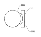
図1は、本発明の液体塗布装置100に係る実施形態の全体構成を示す斜視図である。
ここに示す液体塗布装置100は、概略、塗布媒体に対し所定の塗布液を塗布する液体塗布手段と、この液体塗布手段に塗布液を供給する液体供給手段を有して構成されている。
Preferred embodiments of the present invention will be described below in detail with reference to the accompanying drawings.
FIG. 1 is a perspective view showing an overall configuration of an embodiment according to a
The
液体塗布手段は、円筒状の塗布ローラ1001、この塗布ローラ1001に対向して配置された円筒状のカウンターローラ(媒体支持部材)1002、および塗布ローラ1001を駆動するローラ駆動機構1003などを有する。このローラ駆動機構1003は、ローラ駆動モータ1004と、このローラ駆動モータ1004の駆動力を塗布ローラ1001に伝達するギアトレインなどを有する動力伝達機構1005とによって構成されている。
The liquid application unit includes a
また、液体供給手段は、塗布ローラ1001の周面との間で塗布液を保持する液体保持部材2001、およびこの液体保持部材2001に液体を供給する後述の液体流路3000(図1では不図示)などを有して構成される。塗布ローラ1001およびカウンターローラ1002は、それぞれ、それらの両端が不図示のフレームに対して回動自在に取り付けられた、互いに平行な軸によって回動自在に支持されている。また、液体保持部材2001は、塗布ローラ1001の長手方向のほぼ全体にわたって延在するものであり、塗布ローラ1001の周面に対して接離動作を可能とする機構を介して上記のフレームに移動可能に取り付けられている。
Further, the liquid supply means includes a
本実施形態の液体塗布装置は、さらに、塗布ローラ1001とカウンターローラ1002とのニップ部に塗布媒体を搬送するための、ピックアップローラなどからなる塗布媒体供給機構1006を備える。また、この塗布媒体の搬送路において、塗布ローラ1001およびカウンターローラ1002の後流側には、塗布液が塗布された塗布媒体を排紙部(不図示)へ向けて搬送する、排紙ローラなどからなる排紙機構1007が設けられる。これらの給紙機構や排紙機構も、塗布ローラなどと同様、動力伝達機構1005を介して伝えられる駆動モータ1004の駆動力によって動作する。
The liquid application apparatus according to the present embodiment further includes an application
なお、本実施形態で使用する塗布液は、顔料を色材とするインクで記録した際に顔料の凝集を早めることを目的とした液体である。
塗布する液体の成分の一例を以下に記述する。
硝酸カルシウム・4水和物 10%
グリセリン 42%
界面活性剤 1%
水 残量
また、前記塗布液の粘度は25℃で5〜6cP(センチポアズ)である。
なお、本発明の適用において塗布液は、上記のものに限られないことは勿論である。例えば、別の塗布液として、染料を不溶化あるいは凝集させる成分を含有する液体を用いることも可能である。また、別の塗布液として、塗布媒体のカール(媒体が湾曲形状となる現象)を抑制する成分を含有する液体を用いることも可能である。
Note that the coating liquid used in the present embodiment is a liquid for the purpose of accelerating the aggregation of the pigment when recording with the ink using the pigment as the color material.
An example of the component of the liquid to apply is described below.
Glycerin 42%
Surfactant 1%
The remaining amount of water The viscosity of the coating solution is 5 to 6 cP (centipoise) at 25 ° C.
In the application of the present invention, the coating solution is not limited to the above. For example, it is also possible to use a liquid containing a component that insolubilizes or aggregates the dye as another coating liquid. Further, as another coating liquid, a liquid containing a component that suppresses curling of the coating medium (a phenomenon in which the medium becomes a curved shape) can be used.
塗布する液体に水を用いる場合、本発明の塗布ローラとの液体保持部材の当接部分での周動性は、表面張力を下げる成分を前記液体に含ませることで良好なものとなる。
上述の塗布する液体の成分の一例では、グリセリン及び界面活性剤が水の表面張力を下げる成分である。
When water is used as the liquid to be applied, the peripheral movement at the contact portion of the liquid holding member with the application roller of the present invention is improved by including a component that lowers the surface tension in the liquid.
In an example of the liquid component to be applied, glycerin and a surfactant are components that lower the surface tension of water.
次に、以上概略を説明した液体塗布装置を構成する各部の要素についてより詳細に説明する。
図2は、塗布ローラ1001、カウンターローラ1002および液体保持部材2001などの配置の一例を示す説明縦断側面図である。
カウンターローラ1002は、不図示の付勢手段によって塗布ローラ1001の周面に向けて付勢されており、塗布ローラ1001を図中、時計方向に回転させることにより、両ローラの間に塗布液を塗布すべき塗布媒体Pを挟持し得る。これと共に、塗布媒体Pを図中の矢印方向に搬送し得るようになっている。
Next, the elements of the respective parts constituting the liquid coating apparatus that has been outlined above will be described in more detail.
FIG. 2 is an explanatory vertical side view showing an example of the arrangement of the
The
また、液体保持部材2001は、バネ部材(押圧手段)2006の付勢力によって塗布ローラ1001の周面に対して付勢されて当接するとき、塗布ローラ1001による液体塗布領域全体に亘って延在する長尺な液体保持空間Sを形成するようになっている。この液体保持空間S内には、後述の液体供給経路3000から液体保持部材2001を介して塗布液が供給される。このとき、液体保持部材2001が以下のように構成されているため、塗布ローラ1001の停止状態において、液体保持空間Sから外方へ不用意に塗布液が漏出するのを防止ないしは軽減することができる。
Further, when the
この液体保持部材2100の構成を、図3ないし図8に示す。
図3に示すように、液体保持部材2001は、空間形成基材2002と、この空間形成基材2002の一方の面に設けられた環状の当接部材2009とを有して構成されている。空間形成基材2002には、その中央部分における長手方向に沿って、底部の断面形が円弧状をなす凹部2003が形成される。そして、当接部材2009は、その直線部分がこの凹部2003の上縁部に沿って固着され、また、円周部分が上記上縁部から底部を経て反対側の上縁部に至るように固着される。これにより、液体保持部材2001の当接部2009が塗布ローラ1001に当接したとき、塗布ローラの周面形状に沿った当接が可能となり、均一な圧力の当接を実現することができる。
The configuration of the liquid holding member 2100 is shown in FIGS.
As illustrated in FIG. 3, the
上記のようにこの実施形態における液体保持部材は、継ぎ目のない一体に形成された当接部材2009が、バネ部材2006の付勢力によって塗布ローラ1001の外周面に隙間なく連続した状態で当接する。その結果、液体保持空間Sは、この当接部材2009と、空間形成基材の一面と、塗布ローラ1001の外周面とによる実質的に閉塞した空間となり、この空間に塗布液が保持される。そして、塗布ローラ1001の回転が停止した状態では、当接部材2009と塗布ローラ1001の外周面とは液密状態を維持し、液体が外部へと漏出するのを確実に防止することができる。一方、塗布ローラ1001が回転するときは、後述されるように、塗布液は塗布ローラ1001の外周面と当接部材2009との間をすり抜けて、塗布ローラの外周面に層状に付着する。ここで、塗布ローラ1001の停止状態において、その外周面と当接部材2009とが密接状態にあるとは、上記のとおり、上記液体保持空間Sの内と外との間で液体を通さないことである。この場合、当接部材2009の当接状態としては、それが塗布ローラ1001の外周面に対し、直に接する状態の他、毛管力によって形成される液体の膜を解して上記外周面に当接する状態を含むものである。
As described above, in the liquid holding member in this embodiment, the abutting
また、当接部材2009の長手方向における左右両側部は、図3ないし図8に示すように、正面(図3)、平面(図6)および側面(図7、図8)のいずれの方向から見ても緩やかに湾曲する形状をなしている。このため、塗布ローラ1001に対し、比較的強い押圧力で当接部材2120を当接させても、当接部材2009の全体が略均一に弾性変形し、局所的に大きな歪みが生じることはない。このため、当接部材2009は図6ないし図8に示すように、隙間なく連続的に塗布ローラ1001の外周面に当接し、上記の実質的に閉塞した空間を形成することができる。
Further, the left and right side portions in the longitudinal direction of the abutting
一方、空間形成基材2002には、図3ないし図5に示すように、当接部材2009に囲繞された領域内に、それぞれ空間形成基材2002を貫通する孔を有して構成される液体供給口(供給口)2004および液体回収口(回収口)2005が設けられている。これらは空間形成基材の背面側に突設された円筒状の連結部20041,20051にそれぞれ連通している。また、この連結部20041,20051は、後述の液体供給流路3000に連結されている。なお、この実施形態では、液体供給口2004が当接部材2009に囲繞された領域の一端部(図3では左端部)近傍に形成され、液体回収口2005が同領域の他端部(図3では右端部)近傍に設けられる。この液体供給口2004は、液体流路3000から供給される塗布液を前述の液体保持空間Sに供給し、液体回収口2005は液体保持空間S内の液体を液体流路3000へと流出させるためのものである。この液体の供給、流出を行うことにより、液体保持空間S内において、塗布液は上記の左端部から右端部へと流動する。
On the other hand, as shown in FIGS. 3 to 5, the space-forming
その際、液体保持空間S内を塗布液が流れる間に、圧力損失が起こる。このため、液体供給口2004と、液体回収口2005とで比べた場合、液体供給口2005での負圧が高くなってしまう。前述の通り、負圧が高い方が磨耗量が多くなってしまうことを鑑みると、液体供給口2004と液体回収口2005とでは、回収口2005の方が負圧により磨耗の程度が悪い、すなわち、磨耗の量が多くなる。本実施形態では、装置の搬送経路を含めて供給口2004・回収口2005の場所を配置するものである。というのは、頻繁に塗布媒体が搬送される基準側の磨耗が、塗布液の圧力損失による磨耗で加速されないよう、回収口2005を供給口2004に対して相対的に基準側から遠い方に配置するものである。つまり、基準側に比べて塗布媒体が通る頻度が少なく、それによる磨耗が少ない方の端部を、負圧による磨耗が多い回収口付近に設置することとし、磨耗の原因を分散し、ローラの磨耗による画像弊害を軽減するものである。例えば図1の装置概要で、給紙側から塗布ローラ1001を見た場合の右側を搬送の際の基準側とする。このとき、供給口2004を同じく向かって右、回収口2005を非基準側(向かって左)になるように配置する(図17)。
At that time, pressure loss occurs while the coating liquid flows in the liquid holding space S. For this reason, when compared with the
本明細書において、「基準(突き当て基準とも呼ぶ)、基準点」とは、例えば塗布媒体を塗布ローラ1001やカウンターローラ1002等の塗布手段のニップ部に通す際の、塗布媒体の位置の基準である。よって、塗布媒体の所定の箇所を上記基準に合わせるようにして、上記ニップ部の間で塗布媒体を搬送させるのである。例えば、基準を図17において向かって右側に設定する場合、いずれのサイズの塗布媒体であっても、該塗布媒体の搬送方向右側の端を基準に合わせるようにして搬送する。搬送方向に沿った記録媒体の一端部を規制する部材を右端に設けることで、記録媒体を右端に沿って搬送できるようになる。また、例えば、基準を図18においてほぼ中央に設定する場合、いずれのサイズの塗布媒体であっても、該塗布媒体のほぼ中央を基準に合わせるようにして搬送する。よって、給紙部から塗布ローラへと塗布媒体を搬送させるための搬送路は、塗布媒体の所定の箇所(例えば、図17では、塗布媒体の向かって右側の端)を基準に合わせて搬送できるように設けられる。
In the present specification, “reference (also referred to as abutment reference), reference point” means, for example, a reference for the position of the application medium when the application medium is passed through the nip portion of application means such as the
このように、設定された基準に応じて、塗布媒体における、上記基準と合わせる点(領域)が決められる。なお、上記基準は装置の設計時に設定され、該基準に基づいて、塗布媒体を上記基準に合わせるように搬送させるための搬送路やその制御機構などが設けられる。 In this way, according to the set standard, a point (area) to be matched with the standard in the coating medium is determined. The standard is set at the time of designing the apparatus, and based on the standard, a transport path for transporting the coating medium so as to meet the standard, a control mechanism thereof, and the like are provided.
このように、塗布ローラなどの塗布手段において、基準や基準点近傍では塗布媒体は必ず通る。一方、例えば、回収口2005付近等の非基準側(塗布手段の長手方向に沿った、基準側と所定の距離だけ離れた領域)では、塗布媒体のサイズによっては塗布媒体が通らないこともある。 As described above, in the application means such as the application roller, the application medium always passes in the vicinity of the reference or the reference point. On the other hand, for example, on the non-reference side such as the vicinity of the recovery port 2005 (a region separated from the reference side by a predetermined distance along the longitudinal direction of the application unit), the application medium may not pass depending on the size of the application medium. .
(塗布液流路)
図11は、前記塗布液供給手段の液体保持部材2001に連結される液体流路3000の概略構成を示す説明図である。
この液体流路3000は、液体保持部材2001を構成する空間形成基材2002の液体供給口2004と塗布液を貯蔵する貯蔵タンク3003とを連結する第1流路(供給流路)3001を有する。また、液体流路3000は、空間形成基材2002の液体回収口2005と前記貯蔵タンク3003とを連結する第2流路(回収流路)3002を有する。この貯蔵タンク3003には、大気連通口3004が設けられており、また、この大気連通口には、大気との連通、遮断を切換える大気連通弁3005が設けられている。また、第1流路3001内には切換弁3006が設けられており、この切換弁3006によって第1流路3001と大気との連通、遮断が切換え可能となっている。さらに第2流路3002内には、本液体流路3000内で塗布液および空気を所望の方向へと強制的に流動させるためのポンプ3007が連結されている。
(Coating solution flow path)
FIG. 11 is an explanatory diagram showing a schematic configuration of a
The
なお、図11において、基準点は、図11において向かって左側の位置であって、基準点から回収口2005までの距離が、基準点から供給口2004までの距離よりも遠くなる位置に設定されている。すなわち、基準点に相対的に近い位置に供給口2004が配置され、基準点に相対的に遠い位置に回収口2005が配置される。
In FIG. 11, the reference point is a position on the left side in FIG. 11, and the distance from the reference point to the
また、回収流路である第2流路3002内にポンプ3007が配置されている。よって、図11の矢印方向に塗布液が流動するようにポンプ3007を作動させると、液体保持空間S内の空気または塗布液の少なくとも一方が回収口2005から第2流路3002へと移動するので、液体保持部材2001内は大気圧に対して負圧になる。よって、本実施形態では、塗布液の循環、供給、回収は、負圧方式によって行われる。なお、ポンプ3007を駆動すると、液体保持空間S内の供給口2004側よりも回収口2005側の方が負圧になる。従って、供給口2004側よりも回収口2005側の負圧が大きい状態で、塗布液の循環、供給、回収は行われる。
A
また、この実施形態における切換弁3006は、第1流路3001と大気との連通、遮断を切換え得るものであれば、種々のものが適用可能であるが、ここでは図11に示すような三方弁を使用している。この三方弁3006は、互いに連通する3つのポートを有する。これらポートのうち2つのポートを、第1流路3001における貯蔵タンク側チューブ3011と、液体保持部材側チューブ3012と、大気連通口3013の中のいずれか二つに選択的に連通させることができる。そして、この三方弁3006の切換えにより、チューブ3011とチューブ3012とを連通させる連結状態と、チューブ3012と大気連通口3013とを連通させる連結状態とが選択的に切り換えられる。これにより、液体保持部材2001と塗布ローラ1001とによって形成される液体保持空間Sに対し、貯蔵タンク3003内の塗布液あるいは大気連通口3013から取り込まれる空気の何れかを選択して供給することが可能となる。なお、三方弁3006の切換えは、後述の制御部4000からの制御信号によって行われ、塗布液の充填、供給などが行われる。
(制御系)
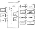
図12は、本実施形態の液体塗布装置における制御系の概略構成を示すブロック図である。
図において、符号4000は液体塗布装置全体を制御する制御手段としての制御部である。この制御部4000は、種々の演算、制御、判別などの処理動作を実行するCPU4001と、このCPU4001によって実行される、図13にて後述される処理などの制御プログラムなどを格納するROM4002とを有する。また、制御部4000は、CPU4001の処理動作中のデータや入力データなどを一時的に格納するRAM4003などを有する。
(Control system)
FIG. 12 is a block diagram showing a schematic configuration of a control system in the liquid coating apparatus of the present embodiment.
In the figure,
この制御部4000には、所定の指令あるいはデータなどを入力するキーボードあるいは各種スイッチなどを含む入力操作部4004、液体塗布装置の入力・設定状態などをはじめとする種々の表示を行う表示部4005がそれぞれ接続されている。また、制御部4000には、塗布媒体の位置や各部の動作状態などを検出するセンサなどを含む検出部4006が接続されている。さらに制御部4000には、前記ローラ駆動モータ1004、ポンプ駆動モータ4009、大気連通弁3005および切換弁3006などがそれぞれ駆動回路4007,4008,4010,4011を介して接続されている。
The
(液体塗布動作シーケンス)
図13は、本実施形態の液体塗布装置の液体塗布に係わる処理手順を示すフローチャートである。以下、このフローチャートを参照して、液体塗布にかかる各工程を説明する。 すなわち、液体塗布装置に電源が投入されると、制御部4000は、図13に示すフローチャートに従って以下の塗布動作シーケンスを実行する。
(Liquid application operation sequence)
FIG. 13 is a flowchart showing a processing procedure related to liquid application of the liquid application apparatus of this embodiment. Hereinafter, with reference to this flowchart, each process concerning liquid application will be described. That is, when power is turned on to the liquid coating apparatus, the
充填工程
ステップS1では、前記塗布空間Sに対する塗布液の充填工程を実行する。この充填工程では、まず、貯蔵タンク3003の大気連通弁3005を大気に開放させると共に、ポンプ3007を一定時間駆動する。これにより、液体塗布空間Sおよび各流路3001,3002内に塗布液が充填されていない場合には、ポンプによって内部の空気が貯留部へと送られて大気へと排出されると共に各部に塗布液が充填される。また、既に各部に塗布液が充填されている場合には、各部の塗布液が流動して適正な濃度および粘度の塗布液が供給される。この初期動作によって、塗布ローラ1001に対し塗布液が供給された状態となり、塗布媒体への塗布が可能となる。
Filling process
In step S1, a coating liquid filling step for the coating space S is performed. In this filling step, first, the
塗布工程
ここで、塗布開始指令が入力されると(ステップS2)、再びポンプ3007が作動を開始する(ステップS3)。このようにして、液体保持空間S内の供給口2004側よりも回収口2005側を負圧にした状態で、液体流路3000内で塗布液を循環させる。次いで、液体流路3000内で塗布液を循環させながら、塗布ローラ1001が図1の矢印に示すように、時計周りに回転を開始する(ステップS4)。この塗布ローラ1001の回転により、液体保持空間Sに充填された塗布液Lは、塗布ローラ1001に対する液体保持部材2001の当接部材2009の押圧力に抗して、塗布ローラ1001と当接部材2009の下縁部2011との間を摺り抜ける。摺り抜けた塗布液は塗布ローラ1001の外周に層状態となって付着する。塗布ローラ1001に付着した塗布液Lは、塗布ローラ1001とカウンターローラ1002との当接部に送られる。
Application process
Here, when an application start command is input (step S2), the
次いで、塗布媒体送給機構1006によって塗布ローラ1001とカウンターローラ1002との間に塗布媒体が搬送され、これらのローラの間に塗布媒体が挿入される。これと共に、挿入された塗布媒体は、塗布ローラ1001とカウンターローラ1002の回転に伴い排紙部へ向けて搬送される(ステップS5)。この搬送の間に、塗布ローラ1001の外周面に塗布された塗布液が、図9に示すように塗布ローラ1001から塗布媒体Pに転写される。なお、塗布ローラ1001とカウンターローラ1002との間に塗布媒体を供給する手段としては、上記の送給機構に限られないことは勿論である。例えば、所定のガイド部材を補助的に用いる手差しによる手段を併せて用いてもよく、また、手差し手段を単独で用いる構成など、どのような手段を用いてもよい。
Next, the application
さて、本実施形態では、上述した通り、ポンプ3007の駆動によって負圧方式で塗布液を循環させながら、塗布ローラによる塗布液の塗布を実行している。そのため、塗布液の塗布時には、液体保持空間S内の供給口2004側よりも回収口2005側の負圧が大きくなる。こうした負圧差は塗布ローラの磨耗量に差異を生じさせ、負圧差に起因した塗布ローラの磨耗量は供給口2004側よりも回収口2005側の方が大きい。
In the present embodiment, as described above, the application liquid is applied by the application roller while the application liquid is circulated by the negative pressure method by driving the
そこで、本実施形態では、負圧による磨耗量が比較的小さい供給口2004を、記録媒体の搬送頻度が比較的多い搬送基準側に配置する。また、負圧による磨耗量が比較的大きい回収口2005の位置を、記録媒体の搬送頻度が比較的少ない非基準側に配置する。すなわち、搬送基準位置に対して、供給口2004よりも相対的に遠い位置に回収口2005を配置するのである。このように負圧による磨耗量が小さい供給口2004を搬送による磨耗量が大きい側に配置し、負圧による磨耗量が大きい回収口2005を搬送による磨耗量が小さい側に配置することで、塗布ローラの左右の磨耗量を比較的均一にできる。
Therefore, in the present embodiment, the
図9において、交差する斜線で表現した部分が塗布液Lを示している。なお、ここでは、塗布ローラ1001および塗布媒体Pにおける塗布液の層の厚みは、塗布時における塗布液Lの様子を明確に図示する上で、実際の厚みよりもかなり過大に表している。
In FIG. 9, a portion expressed by crossing oblique lines indicates the coating liquid L. Here, the thickness of the coating liquid layer on the
上記のようにして、塗布媒体Pの塗布された部分は塗布ローラ2001の搬送力により矢印方向に搬送されると共に、塗布媒体Pと塗布ローラ2001の接触部に塗布媒体Pの未塗布部分が搬送される。この動作を連続もしくは間欠的に行うことで塗布媒体全体に塗布液を塗布して行く。
As described above, the coated portion of the coating medium P is transported in the direction of the arrow by the transport force of the
ところで、塗布液は潤滑剤としての働きもある。後で詳しく述べるが、塗布ローラ1001の表面に供給された塗布液は塗布媒体へと塗布されるため、塗布媒体が通った後の塗布ローラには少量しか塗布液が残っていない。これにより、塗布ローラが再びキャップ(液体保持部材2001)のニップ部に突入するポイントで潤滑剤としての塗布液が不足し摩擦が大きくなり、塗布ローラの通紙部が磨耗してしまう。図9は、通紙部(塗布ローラ表面における、塗布媒体と接触する領域、すなわち、塗布媒体が通る領域)の模式図である。また、図10は、非通紙部(例えば最大でA3サイズの塗布媒体に塗布可能な塗布ローラにおいて、A4サイズの記録媒体を通紙した場合の、非基準側であって、塗布媒体が通らない部分のこと)の模式図である。
By the way, the coating liquid also functions as a lubricant. As will be described in detail later, since the application liquid supplied to the surface of the
図21,図22,図23は、媒体Pが普通紙である場合における媒体の表面と塗布面での塗布過程を説明する説明図である。本図では液体を黒く塗りつぶしてある。
図21は塗布ローラ1001とカウンターローラ1002とのニップ部より上流側での状態を示している。同図において塗布ローラ1001の塗布面には液体が塗布面の表面の微細な凹凸をわずかに被うように液体が付着している。
図22は塗布ローラ1001とカウンターローラ1002とのニップ部での、媒体Pである普通紙の表面と塗布ローラ1001の塗布面の状態を示している。同図において媒体Pである普通紙の表面の凸部は塗布ローラ1001の塗布面と接触し、接触した部分より液体が瞬時に媒体Pである普通紙の表面の繊維に浸透ないし吸着する。また塗布ローラ1001の塗布面には普通紙の表面の凸部と接触しない部分に付着した液体が残留される。
21, 22, and 23 are explanatory diagrams for explaining the application process on the surface and the application surface of the medium when the medium P is plain paper. In this figure, the liquid is painted black.
FIG. 21 shows a state upstream of the nip portion between the
FIG. 22 shows the state of the surface of plain paper as the medium P and the application surface of the
図23は塗布ローラ1001とカウンターローラ1002とのニップ部より下流側での状態を示している。同図は媒体と塗布ローラ1001の塗布面が完全に離脱した状態である。塗布ローラ1001の塗布面には普通紙の表面の凸部と接触しない部分に残留した液体と接触部における液体も極微量ながら塗布面に残留する。
FIG. 23 shows a state downstream of the nip portion between the
また、この塗布ローラ1001に残留した塗布液は、塗布ローラ1001に対する液体保持部材2001の当接部材2009の押圧力に抗して、塗布ローラ1001と当接部材2009の上縁部2010との間を摺り抜けて液体保持空間S内に戻る。この液体保持空間S内に戻った塗布液は、同空間S内に充填されている塗布液と混合される。
Further, the coating liquid remaining on the
さらに、この塗布液の戻し動作は、図10に示すように塗布媒体が存在しない状態で塗布ローラ1001を回転させた場合にも同様に行われる。すなわち、塗布ローラ1001を回転することで塗布ローラ1001の外周に付着した塗布液は、カウンターローラ1002と当接する部分(ニップ部)の間をすり抜ける。すり抜けた後は塗布ローラ1001側とカウンターローラ1002側とに塗布液が分離し、塗布ローラ1001に塗布液が残留する。そして、塗布ローラ1001側に付着した塗布液Lは当接部材2009の上縁部2010と塗布ローラ1001との間をすり抜けて液体保持空間S内に侵入し、同空間S内に充填されている塗布液に混合する。
Further, the returning operation of the coating liquid is similarly performed when the
終了工程
上記のようにして、塗布媒体への塗布動作が実行されると、次に塗布工程を終了して良いか否かの判断を行い(ステップS6)、塗布工程を終了しない場合は、ステップS5に戻り、塗布媒体の塗布が必要な部分全体に塗布工程を終了するまで塗布動作を繰り返す。塗布工程を終了すると、塗布ローラ1001を停止させ(ステップS7)、さらに、ポンプ3007の駆動を停止させる(ステップS8)。この後、ステップS2へ移行し、塗布開始指令が入力されていれば、前述のステップS2〜S8の動作を繰り返す。一方、塗布開始指令が入力されていなければ、液体保持空間Sおよび液体流路内の塗布液を回収する回収動作などの後処理を行い(ステップ9)、塗布にかかる処理を終了する。
End process
As described above, when the application operation to the application medium is executed, it is determined whether or not the application process can be completed next (step S6). If the application process is not ended, the process proceeds to step S5. Returning, the coating operation is repeated until the coating process is completed on the entire portion where coating of the coating medium is required. When the application process is completed, the
なお、上記回収動作は、前記大気連通弁3005および切換弁3006を開放し、ポンプ3007を駆動することによって塗布液を塗布液保持空間Sおよび第2流路3002内の塗布液を液体貯留タンク3003へと流入させることによって行う。この回収動作を行うことにより、液体保持空間Sからの塗布液の蒸発を完全に防止ないしは緩和することができる。また、回収動作後は大気連通弁3005を閉じ、切換弁3006を切換えて第1流路3001および大気連通口3013との連通を遮断することにより、貯蔵タンク3003を大気から遮断する。これにより、液体貯蔵タンク3003からの塗布液の蒸発を防止ないしは軽減することができると共に、移動、運搬などにおいて装置の姿勢が傾いた場合にも塗布液が外部へ流出するのを完全に防止ないしは軽減することができる。
In the recovery operation, the
このように、本実施形態によれば、負圧方式において、基準に対して相対的に近い位置に供給口を配置し、基準に対して相対的に遠い位置に回収口を配置しているので、負圧による磨耗と、塗布液が少ないことによる磨耗とを分散することができる。すなわち、塗布媒体への塗布によりローラ表面に残った塗布液が少なくなる、または無くなることによって生じる磨耗に対して、負圧による磨耗の影響を及ぼすことを軽減することができる。よって、塗布ローラやカウンターローラ等の塗布に関るローラの磨耗の原因を分散することができ、塗布液の塗りムラによる画像の弊害等、ローラの磨耗による画像弊害を軽減することが可能となる。
さて、本実施形態は、塗布媒体への塗布によるローラ表面の塗布液残量が十分でないことによるローラの磨耗に対して、負圧によるローラの磨耗の影響を軽減させるために、回収口を基準点に対して、供給口よりも相対的に遠い位置に配置している。よって、基準点に対して、回収口と供給口との位置関係を上述のようであればいずれの関係であっても良い。
Thus, according to this embodiment, in the negative pressure method, the supply port is disposed at a position relatively close to the reference, and the recovery port is disposed at a position relatively far from the reference. It is possible to disperse wear due to negative pressure and wear due to a small amount of coating liquid. That is, it is possible to reduce the influence of the wear due to the negative pressure on the wear caused when the coating liquid remaining on the roller surface is reduced or eliminated due to the application to the application medium. Therefore, it is possible to disperse the causes of wear of the roller related to the application such as the application roller and the counter roller, and it is possible to reduce the image adverse effects due to the abrasion of the rollers, such as the adverse effects of the image due to the uneven coating of the coating liquid. .
In the present embodiment, the recovery port is used as a reference in order to reduce the influence of the roller wear due to the negative pressure against the wear of the roller due to the remaining amount of the coating liquid on the roller surface due to the application to the application medium. It arrange | positions in the position relatively distant from the supply port with respect to the point. Therefore, any relationship may be used as long as the positional relationship between the recovery port and the supply port is as described above with respect to the reference point.
なお、塗布媒体のサイズ等を考慮するとより好ましい位置関係がある。例えば、液体塗布装置でサポートされる最大の塗布媒体のサイズがA3であり、最も頻繁に塗布を行う塗布媒体のサイズがA4である場合はより好ましい位置関係は、以下の通りである。すなわち、A4サイズの塗布媒体を基準点に突き当てた(合わせた)場合、基準点に対して、該塗布媒体の基準点とは反対側の端よりも相対的に遠い位置に回収口を配置すれば良い。
このように、供給口は、総てのサイズの媒体と当接する塗布ローラの搬送方向と直交する方向の位置に対向する液体保持部材2001上に配置することが好ましい。一方、回収口は、一部のサイズの媒体だけと当接する塗布ローラの搬送方向と直交する方向の位置に対向する液体保持部材2001上の位置に配置することが好適である。
Note that there is a more preferable positional relationship in consideration of the size of the coating medium and the like. For example, when the size of the largest application medium supported by the liquid application apparatus is A3 and the size of the application medium that is most frequently applied is A4, the more preferable positional relationship is as follows. That is, when an A4 size coating medium is abutted (matched) to the reference point, the recovery port is disposed at a position relatively far from the reference point on the side opposite to the reference point of the coating medium. Just do it.
Thus, the supply port is preferably disposed on the
また、いずれのサイズの塗布媒体に塗布する場合でも、塗布ローラの表面の、液体塗布装置でサポートされる最小の塗布媒体が通る領域を、塗布媒体のサイズに関らず塗布媒体は必ず通過する。よって、上記最小サイズの塗布媒体を基準点に突き当てた場合、基準点に対して、該塗布媒体の基準点とは反対側の塗布媒体の端よりも相対的に遠い位置に回収口を配置することも好ましい。 In addition, regardless of the size of the application medium, the application medium always passes through the area on the surface of the application roller through which the minimum application medium supported by the liquid application apparatus passes, regardless of the size of the application medium. . Therefore, when the minimum-size coating medium is abutted against the reference point, the recovery port is disposed at a position relatively far from the reference point of the coating medium opposite to the reference point of the coating medium. It is also preferable to do.
(第2の実施形態)
次に、本発明の他の実施形態の要部を図18に基き説明する。
本実施形態では、搬送時の基準が、塗布ローラ1001のほぼ中心にある場合を想定している。第1の実施形態では、記録媒体を塗布ローラ端部の片方に突き当てて搬送しているため、塗布ローラの片側のみが徐々にけずれていくが、本実施形態では、基準をほぼ中心にとる。そのため、片側のみと言わず、基準となる中心付近から対称系にローラが削れてしまう。
(Second Embodiment)
Next, a main part of another embodiment of the present invention will be described with reference to FIG.
In this embodiment, it is assumed that the reference at the time of conveyance is substantially at the center of the
この場合も同じように、基準から見て供給口2004よりも相対的に遠い位置、つまりこの場合は、塗布ローラ1001の両端のどちらか一方、または両方に回収口2005を設ければ良い。もし、液体供給口2004を基準と同じ塗布ローラ1001の中心付近に配置する場合は、塗布ローラ1001の両端のどちらか、もしくはその両方に回収口2005を配置する。というのも、本発明の一実施形態において、液体保持部材2001に形成する供給口2004および回収口2005の形成位置および数は、上記実施形態に限定されないからである。
Similarly, in this case, the
例えば、図18に示すように、液体回収口を液体保持空間内の両端部に配置し、その両液体回収口の間に一つまたは複数の液体供給口を配置しても良い。要は、基準とほぼ同じ位置または、基準に対して相対的に近い位置に液体供給口を配置し、相対的に遠い位置に液体回収口を配置して、液体保持部材内に保持される液体が液体保持空間内で流動可能になれば良い。 For example , as shown in FIG. 18, the liquid recovery ports may be arranged at both ends in the liquid holding space, and one or a plurality of liquid supply ports may be arranged between the two liquid recovery ports. The point is that the liquid held in the liquid holding member by disposing the liquid supply port at substantially the same position as the reference or a position relatively close to the reference and disposing the liquid recovery port at a relatively distant position. It is only necessary that the fluid can flow in the liquid holding space.
(他の実施形態)
第1および第2の実施形態では、液体保持部材2001に塗布ローラ1001を当接することにより、シール性(液密状態)に優れた液体保持空間Sを形成しているが、これに限定されない。例えば、特許文献1に記載されているようなチャンバーを塗布ローラの周面に当接することにより、上記液体保持空間を形成するようにしても良い。すなわち、液体保持空間を形成するための部材として、液体供給口と液体回収口とを有し、塗布ローラに当接することにより液体保持空間を形成し、負圧により上記空間に対して塗布液の循環、供給、回収等を行える部材であれば、いずれの部材を用いても良い。
(Other embodiments)
In the first and second embodiments, the liquid holding space S having excellent sealing properties (liquid-tight state) is formed by bringing the
(インクジェット記録装置の実施形態)
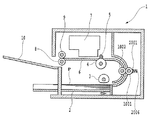
図19は、上述の液体塗布装置とほぼ同様の構成を有した塗布機構を備えたインクジェット記録装置1の概略構成を示す図である。
このインクジェット記録装置1には、複数枚の記録媒体Pを積載する給送トレイ2が設けられており、半月形状の分離ローラ3が、給送トレイに積載された記録媒体Pを1枚づつ分離して搬送経路に給送する。搬送経路中には、上記液体塗布機構の液体塗布手段を構成する塗布ローラ1001およびカウンターローラ1002が配置されている。この構成により、給送トレイ2から給送された記録媒体Pは、装置毎に任意に決められた基準に突き当てられて両ローラ1001,1002の間に送られる。塗布ローラ1001はローラ駆動モータの回転によって図19において時計周り方向に回転し、記録媒体Pを搬送しながら塗布液を記録媒体Pの記録面に塗布する。塗布液が塗布された記録媒体Pは、搬送ローラ4とピンチローラ5との間に送られ、搬送ローラ4が、図中、反時計周り方向へと回転することによって、記録媒体Pはプラテン6の上を搬送される。搬送された記録媒体Pは、記録手段を構成する記録ヘッド7に対向する位置へと移動する。記録ヘッド7は所定数のインク吐出用のノズルを配設したインクジェット記録ヘッドであり、この記録ヘッド7が図の紙面と垂直方向に走査する間に、記録データに従ってノズルから記録媒体Pの記録面に対してインク滴を吐出して記録を行う。この記録動作と搬送ローラ4による所定量の搬送動作とを交互に繰り返しながら、記録媒体に画像を形成して行く。この画像形成動作とともに、記録媒体の搬送路において記録ヘッドの走査領域の後流側に設けられた、排紙ローラ8と排紙拍車9によって記録媒体Pが挟持され、排紙ローラ8の回転によって排紙トレイ10上に排紙される。
(Embodiment of inkjet recording apparatus)
FIG. 19 is a diagram illustrating a schematic configuration of the
The
なお、このインクジェット記録装置としては、インクを吐出するノズルを記録媒体の最大幅に亘って配設した長尺な記録ヘッドを用いて記録動作を行ういわゆるフルライン型のインクジェット記録装置を構成することも可能である。 As the ink jet recording apparatus, a so-called full line type ink jet recording apparatus that performs a recording operation using a long recording head in which nozzles for ejecting ink are arranged over the maximum width of the recording medium is configured. Is also possible.
また、この実施形態で用いる塗布液は、顔料を色材とするインクで記録した際に顔料の凝集を早める処理液である。この実施形態では、塗布液として処理液を用いることにより、この処理液とこの処理液が塗布された記録媒体に吐出されるインクの色材である顔料を反応させて顔料の凝集を早めさせる。そして、この不溶化により、記録濃度の向上を図ることができる。さらに、ブリーディングの軽減または防止が可能となる。なお、インクジェット記録装置において用いる塗布液としては、上述の例に限られないことは勿論である。 The coating liquid used in this embodiment is a processing liquid that accelerates the aggregation of the pigment when recording with the ink using the pigment as the color material. In this embodiment, by using the treatment liquid as the coating liquid, the pigment that is the color material of the ink discharged onto the recording medium coated with the treatment liquid is reacted to accelerate the aggregation of the pigment. This insolubilization can improve the recording density. Furthermore, bleeding can be reduced or prevented. Needless to say, the coating liquid used in the ink jet recording apparatus is not limited to the above example.
図20は、上述したインクジェット記録装置の要部を示す斜視図である。同図に示すように、給送トレイ2の一端の上方に塗布機構100が設けられ、この塗布機構より上部で、給送トレイ2の中央部上方に記録ヘッド7などを備えた記録機構が設けられる。
FIG. 20 is a perspective view showing a main part of the above-described ink jet recording apparatus. As shown in the figure, a
なお、本実施形態では、記録媒体に対する液体塗布に伴い、その塗布が終了した部分に対して順次記録を行うものである。すなわち、塗布ローラから記録ヘッドへ至る搬送路の長さが記録媒体の長さよりも短く、記録媒体上の液体の塗布がなされた部分が記録ヘッドによる走査領域に至るときに、記録媒体の他の部分に塗布機構によって塗布が行われる形態である。記録媒体の所定量の搬送ごとに、記録媒体の異なる部分で、順次、液体塗布と記録がなされていく。しかし、本発明の適用する上で、別の形態として、特許文献3に記載されるように、1つの記録媒体に対する塗布が完了してから記録を行うものであってもよい。
In the present embodiment, recording is sequentially performed on a portion where the application has been completed as the liquid application is performed on the recording medium. That is, when the length of the conveyance path from the coating roller to the recording head is shorter than the length of the recording medium, and the portion where the liquid is applied on the recording medium reaches the scanning area by the recording head, In this mode, application is performed on the portion by an application mechanism. Each time a predetermined amount of the recording medium is conveyed, liquid application and recording are sequentially performed in different portions of the recording medium. However, when the present invention is applied, as another embodiment, recording may be performed after application to one recording medium is completed, as described in
また、本発明における記録装置においては、液体塗布機構によって、蛍光増白剤を含有する液体を塗布することにより、媒体の白色度を向上させることが可能である。このとき、前記液体塗布後の記録手段は、インクジェット記録方式に限られず、熱転写方式、電子写真方式などの記録方式でも効果を得ることができる。
また、銀塩写真方式の記録装置において、記録前に、感光剤を塗布してもよい。
In the recording apparatus of the present invention, the whiteness of the medium can be improved by applying a liquid containing a fluorescent brightening agent by a liquid application mechanism. At this time, the recording means after applying the liquid is not limited to the ink jet recording method, and the effect can be obtained by a recording method such as a thermal transfer method and an electrophotographic method.
In a silver halide photographic recording apparatus, a photosensitive agent may be applied before recording.
100 液体塗布装置
1001 塗布ローラ
1002 カウンターローラ
2001 液体保持部材
2004 液体供給口
2005 液体回収口
3000 液体流路
3001 第1流路
3002 第2流路
3003 貯蔵タンク
3004 大気連通口
3005 大気連通弁
3006 切換弁
3007 ポンプ
DESCRIPTION OF
Claims (5)
複数の異なるサイズの媒体を、いずれも媒体の搬送方向と直交する方向における中心が同一の基準位置を通るように搬送する搬送手段と、
前記搬送手段により搬送される媒体に液体を塗布するための塗布ローラおよび前記塗布ローラに当接して形成される液体保持空間に液体を保持するための保持部材を含み、前記塗布ローラを回転させることにより前記液体保持空間内の液体を前記塗布ローラを介して前記媒体に塗布する液体塗布手段と、
前記液体を貯蔵する貯蔵手段と、
前記貯蔵手段内の液体を前記液体保持空間へ供給するための供給路と、
前記液体保持空間内の液体を前記貯蔵手段に回収するための回収路と、
前記保持部材に形成され、前記供給路に接続された供給口と、
前記保持部材に形成され、前記回収路に接続された回収口と、
前記貯蔵手段、前記供給路、前記液体保持空間および前記回収路を含む流路において前記液体の流れを発生させるためのポンプと
を備え、
前記ポンプは前記回収路に設けられており、
前記基準位置に対して相対的に近い位置に前記供給口が配置され、前記基準位置に対して相対的に遠く且つ前記供給口を挟んだ複数の位置に前記回収口が配置されていることを特徴とする液体塗布装置。 A liquid application apparatus capable of applying liquid to a medium body,
Transport means for transporting a plurality of media of different sizes so that the centers in the direction orthogonal to the transport direction of the medium all pass the same reference position ;
It includes holding members for holding the liquid to the liquid holding space formed in contact with the application roller and the application roller for applying the liquid to the medium conveyed by the conveying means, to rotate the application roller Liquid applying means for applying the liquid in the liquid holding space to the medium via the application roller ;
Storage means for storing the liquid;
A supply path for supplying the liquid in the storage means to the liquid holding space;
A recovery path for recovering the liquid in the liquid holding space to the storage means;
A supply port formed in the holding member and connected to the supply path;
A recovery port formed in the holding member and connected to the recovery path;
A pump for generating a flow of the liquid in a flow path including the storage means, the supply path, the liquid holding space, and the recovery path;
The pump is provided in the recovery path;
It is the supply port is disposed relatively close to the front Kimoto reference position, wherein the recovery port is arranged in a plurality of locations across the relatively far and the supply port with respect to the reference position A liquid coating apparatus characterized by that.
複数の異なるサイズの媒体を、いずれも媒体の搬送方向と直交する方向における中心が同一の基準位置を通るように搬送する搬送手段と、
前記搬送手段により搬送される媒体に液体を塗布するための塗布ローラおよび前記塗布ローラに当接して形成される液体保持空間に液体を保持するための保持部材を含み、前記塗布ローラを回転させることにより、前記液体保持空間に保持される液体を前記塗布ローラを介して前記媒体に塗布する液体塗布手段と、
前記保持部材に形成され、前記液体保持空間に前記液体を供給するための供給口と、
前記保持部材に形成され、前記液体保持空間から前記液体を排出するための排出口と、
前記液体塗布手段により前記液体を前記媒体に塗布している間、前記液体保持空間内の液体を前記排出口から排出させることにより、前記液体保持空間内の回収口側を前記供給口側よりも負圧にする負圧発生手段と
を備え、
前記基準位置に対して相対的に近い位置に前記供給口が配置され、前記基準位置に対して相対的に遠い複数の位置に前記回収口が配置されていることを特徴とする液体塗布装置。 A liquid application apparatus capable of applying liquid to a medium body,
Transport means for transporting a plurality of media of different sizes so that the centers in the direction orthogonal to the transport direction of the medium all pass the same reference position ;
It includes holding members for holding the liquid to the liquid holding space formed in contact with the application roller and the application roller for applying the liquid to the medium conveyed by the conveying means, to rotate the application roller Liquid applying means for applying the liquid held in the liquid holding space to the medium via the application roller ;
A supply port formed in the holding member for supplying the liquid to the liquid holding space;
A discharge port formed in the holding member for discharging the liquid from the liquid holding space;
While the liquid is applied to the medium by the liquid application means, the liquid in the liquid holding space is discharged from the discharge port, so that the recovery port side in the liquid holding space is more than the supply port side. Negative pressure generating means for making negative pressure,
The supply port is disposed in a position relatively close to the front Kimoto reference position, the liquid coating, characterized in that the recovery port relatively far plurality of positions with respect to the reference position is located apparatus.
Priority Applications (1)
| Application Number | Priority Date | Filing Date | Title |
|---|---|---|---|
| JP2006275307A JP4906460B2 (en) | 2005-12-06 | 2006-10-06 | Liquid applicator |
Applications Claiming Priority (3)
| Application Number | Priority Date | Filing Date | Title |
|---|---|---|---|
| JP2005352507 | 2005-12-06 | ||
| JP2005352507 | 2005-12-06 | ||
| JP2006275307A JP4906460B2 (en) | 2005-12-06 | 2006-10-06 | Liquid applicator |
Publications (3)
| Publication Number | Publication Date |
|---|---|
| JP2007181809A JP2007181809A (en) | 2007-07-19 |
| JP2007181809A5 JP2007181809A5 (en) | 2009-11-19 |
| JP4906460B2 true JP4906460B2 (en) | 2012-03-28 |
Family
ID=38338313
Family Applications (1)
| Application Number | Title | Priority Date | Filing Date |
|---|---|---|---|
| JP2006275307A Expired - Fee Related JP4906460B2 (en) | 2005-12-06 | 2006-10-06 | Liquid applicator |
Country Status (1)
| Country | Link |
|---|---|
| JP (1) | JP4906460B2 (en) |
Families Citing this family (2)
| Publication number | Priority date | Publication date | Assignee | Title |
|---|---|---|---|---|
| JP5602476B2 (en) * | 2010-04-02 | 2014-10-08 | キヤノン株式会社 | Liquid coating apparatus and recording apparatus |
| JP5998485B2 (en) * | 2012-01-13 | 2016-09-28 | ブラザー工業株式会社 | Liquid ejection device |
Family Cites Families (2)
| Publication number | Priority date | Publication date | Assignee | Title |
|---|---|---|---|---|
| JPH06263268A (en) * | 1993-03-15 | 1994-09-20 | Ricoh Co Ltd | Image forming device |
| JP4748768B2 (en) * | 2004-02-12 | 2011-08-17 | キヤノン株式会社 | Inkjet recording device |
-
2006
- 2006-10-06 JP JP2006275307A patent/JP4906460B2/en not_active Expired - Fee Related
Also Published As
| Publication number | Publication date |
|---|---|
| JP2007181809A (en) | 2007-07-19 |
Similar Documents
| Publication | Publication Date | Title |
|---|---|---|
| JP4533275B2 (en) | Liquid coating apparatus and inkjet recording apparatus | |
| JP4533274B2 (en) | Liquid coating apparatus and inkjet recording apparatus | |
| JP4498148B2 (en) | Liquid applicator, recording device | |
| JP4617383B2 (en) | Inkjet recording device | |
| US8001921B2 (en) | Liquid application device and inkjet recording apparatus | |
| US7270409B2 (en) | Liquid applying apparatus and ink jet printing apparatus | |
| US7650850B2 (en) | Liquid applying apparatus and ink jet printing apparatus | |
| JP2007044647A (en) | Liquid application apparatus and ink-jet recording apparatus | |
| JP5116471B2 (en) | Liquid coating apparatus and inkjet recording apparatus | |
| JP4355586B2 (en) | Liquid coating apparatus and inkjet recording apparatus | |
| JP2007117807A (en) | Liquid coating device, and recording apparatus | |
| JP4906460B2 (en) | Liquid applicator | |
| JP4677246B2 (en) | Inkjet recording device | |
| JP2007117806A (en) | Liquid coating device and recording apparatus | |
| JP2010143014A (en) | Recording apparatus and recording method | |
| JP4642360B2 (en) | Liquid applicator, recording device | |
| JP4748768B2 (en) | Inkjet recording device | |
| JP4355662B2 (en) | Inkjet recording device | |
| JP4384086B2 (en) | Liquid coating apparatus and inkjet recording apparatus | |
| JP4480159B2 (en) | Liquid applicator, recording device | |
| JP4508978B2 (en) | Liquid coating apparatus and inkjet recording apparatus | |
| JP2008149231A (en) | Liquid coater and ink jet recorder | |
| JP2005224701A (en) | Liquid coating device and inkjet recording device |
Legal Events
| Date | Code | Title | Description |
|---|---|---|---|
| A521 | Written amendment |
Free format text: JAPANESE INTERMEDIATE CODE: A523 Effective date: 20091006 |
|
| A621 | Written request for application examination |
Free format text: JAPANESE INTERMEDIATE CODE: A621 Effective date: 20091006 |
|
| RD02 | Notification of acceptance of power of attorney |
Free format text: JAPANESE INTERMEDIATE CODE: A7422 Effective date: 20101106 |
|
| A977 | Report on retrieval |
Free format text: JAPANESE INTERMEDIATE CODE: A971007 Effective date: 20110908 |
|
| A131 | Notification of reasons for refusal |
Free format text: JAPANESE INTERMEDIATE CODE: A131 Effective date: 20110916 |
|
| A521 | Written amendment |
Free format text: JAPANESE INTERMEDIATE CODE: A523 Effective date: 20111104 |
|
| A131 | Notification of reasons for refusal |
Free format text: JAPANESE INTERMEDIATE CODE: A131 Effective date: 20111125 |
|
| A521 | Written amendment |
Free format text: JAPANESE INTERMEDIATE CODE: A523 Effective date: 20111209 |
|
| TRDD | Decision of grant or rejection written | ||
| A01 | Written decision to grant a patent or to grant a registration (utility model) |
Free format text: JAPANESE INTERMEDIATE CODE: A01 Effective date: 20120106 |
|
| A01 | Written decision to grant a patent or to grant a registration (utility model) |
Free format text: JAPANESE INTERMEDIATE CODE: A01 |
|
| A61 | First payment of annual fees (during grant procedure) |
Free format text: JAPANESE INTERMEDIATE CODE: A61 Effective date: 20120110 |
|
| FPAY | Renewal fee payment (event date is renewal date of database) |
Free format text: PAYMENT UNTIL: 20150120 Year of fee payment: 3 |
|
| FPAY | Renewal fee payment (event date is renewal date of database) |
Free format text: PAYMENT UNTIL: 20150120 Year of fee payment: 3 |
|
| LAPS | Cancellation because of no payment of annual fees |