JP4480159B2 - Liquid applicator, recording device - Google Patents
Liquid applicator, recording device Download PDFInfo
- Publication number
- JP4480159B2 JP4480159B2 JP2005168568A JP2005168568A JP4480159B2 JP 4480159 B2 JP4480159 B2 JP 4480159B2 JP 2005168568 A JP2005168568 A JP 2005168568A JP 2005168568 A JP2005168568 A JP 2005168568A JP 4480159 B2 JP4480159 B2 JP 4480159B2
- Authority
- JP
- Japan
- Prior art keywords
- application
- liquid
- contact position
- coating
- roller
- Prior art date
- Legal status (The legal status is an assumption and is not a legal conclusion. Google has not performed a legal analysis and makes no representation as to the accuracy of the status listed.)
- Expired - Fee Related
Links
- 239000007788 liquid Substances 0.000 title claims description 333
- 238000000576 coating method Methods 0.000 claims description 209
- 239000011248 coating agent Substances 0.000 claims description 203
- 238000000034 method Methods 0.000 claims description 36
- 239000000463 material Substances 0.000 claims description 20
- 238000003860 storage Methods 0.000 claims description 16
- 238000004040 coloring Methods 0.000 claims description 4
- 238000004891 communication Methods 0.000 description 19
- 230000002093 peripheral effect Effects 0.000 description 18
- 239000012298 atmosphere Substances 0.000 description 15
- 238000012545 processing Methods 0.000 description 13
- 239000000049 pigment Substances 0.000 description 10
- 238000010586 diagram Methods 0.000 description 9
- 238000011084 recovery Methods 0.000 description 9
- 238000006073 displacement reaction Methods 0.000 description 8
- 229920001971 elastomer Polymers 0.000 description 5
- 239000005060 rubber Substances 0.000 description 5
- 238000007789 sealing Methods 0.000 description 5
- 239000000758 substrate Substances 0.000 description 5
- 238000012546 transfer Methods 0.000 description 5
- PEDCQBHIVMGVHV-UHFFFAOYSA-N Glycerine Chemical compound OCC(O)CO PEDCQBHIVMGVHV-UHFFFAOYSA-N 0.000 description 4
- 238000004220 aggregation Methods 0.000 description 4
- 230000002776 aggregation Effects 0.000 description 4
- 238000003825 pressing Methods 0.000 description 4
- 230000005540 biological transmission Effects 0.000 description 3
- 230000000903 blocking effect Effects 0.000 description 3
- 230000001186 cumulative effect Effects 0.000 description 3
- 238000001704 evaporation Methods 0.000 description 3
- 230000008020 evaporation Effects 0.000 description 3
- 238000000926 separation method Methods 0.000 description 3
- XLYOFNOQVPJJNP-UHFFFAOYSA-N water Substances O XLYOFNOQVPJJNP-UHFFFAOYSA-N 0.000 description 3
- 229920002943 EPDM rubber Polymers 0.000 description 2
- 229920000459 Nitrile rubber Polymers 0.000 description 2
- 238000009825 accumulation Methods 0.000 description 2
- 230000000740 bleeding effect Effects 0.000 description 2
- 239000003795 chemical substances by application Substances 0.000 description 2
- 238000001514 detection method Methods 0.000 description 2
- 238000007599 discharging Methods 0.000 description 2
- 235000011187 glycerol Nutrition 0.000 description 2
- 238000007646 gravure printing Methods 0.000 description 2
- 238000005259 measurement Methods 0.000 description 2
- 239000003973 paint Substances 0.000 description 2
- 239000004094 surface-active agent Substances 0.000 description 2
- 238000011144 upstream manufacturing Methods 0.000 description 2
- ZHJGWYRLJUCMRT-UHFFFAOYSA-N 5-[6-[(4-methylpiperazin-1-yl)methyl]benzimidazol-1-yl]-3-[1-[2-(trifluoromethyl)phenyl]ethoxy]thiophene-2-carboxamide Chemical compound C=1C=CC=C(C(F)(F)F)C=1C(C)OC(=C(S1)C(N)=O)C=C1N(C1=C2)C=NC1=CC=C2CN1CCN(C)CC1 ZHJGWYRLJUCMRT-UHFFFAOYSA-N 0.000 description 1
- 230000004931 aggregating effect Effects 0.000 description 1
- 229910052782 aluminium Inorganic materials 0.000 description 1
- XAGFODPZIPBFFR-UHFFFAOYSA-N aluminium Chemical compound [Al] XAGFODPZIPBFFR-UHFFFAOYSA-N 0.000 description 1
- 239000011324 bead Substances 0.000 description 1
- 230000015572 biosynthetic process Effects 0.000 description 1
- 238000005282 brightening Methods 0.000 description 1
- 239000000835 fiber Substances 0.000 description 1
- 238000011835 investigation Methods 0.000 description 1
- 239000011344 liquid material Substances 0.000 description 1
- 229910052751 metal Inorganic materials 0.000 description 1
- 239000002184 metal Substances 0.000 description 1
- 230000000149 penetrating effect Effects 0.000 description 1
- 239000012466 permeate Substances 0.000 description 1
- 238000012805 post-processing Methods 0.000 description 1
- 238000007639 printing Methods 0.000 description 1
- 229920002379 silicone rubber Polymers 0.000 description 1
- 239000004945 silicone rubber Substances 0.000 description 1
- 229910052709 silver Inorganic materials 0.000 description 1
- 239000004332 silver Substances 0.000 description 1
- -1 silver halide Chemical class 0.000 description 1
- 230000003746 surface roughness Effects 0.000 description 1
Images


Classifications
-
- B—PERFORMING OPERATIONS; TRANSPORTING
- B41—PRINTING; LINING MACHINES; TYPEWRITERS; STAMPS
- B41J—TYPEWRITERS; SELECTIVE PRINTING MECHANISMS, i.e. MECHANISMS PRINTING OTHERWISE THAN FROM A FORME; CORRECTION OF TYPOGRAPHICAL ERRORS
- B41J11/00—Devices or arrangements of selective printing mechanisms, e.g. ink-jet printers or thermal printers, for supporting or handling copy material in sheet or web form
- B41J11/0015—Devices or arrangements of selective printing mechanisms, e.g. ink-jet printers or thermal printers, for supporting or handling copy material in sheet or web form for treating before, during or after printing or for uniform coating or laminating the copy material before or after printing
Description
本発明は、液体塗布装置およびインクジェット記録装置に関し、詳しくは、顔料を色材とするインクで記録した際に顔料の凝集を早めるなど所定の目的で媒体に液体を塗布する液体塗布装置に関するものであり、また、同様に、インクジェット記録で用いられる記録媒体に対して、顔料を色材とするインクで記録した際に顔料の凝集を早めるなどの目的で液体を塗布する機構を備えたインクジェット記録装置に関するものである。 The present invention relates to a liquid coating apparatus and an ink jet recording apparatus, and more particularly to a liquid coating apparatus that applies a liquid to a medium for a predetermined purpose such as aggregating the pigment when recording with an ink using a pigment as a coloring material. Similarly, an ink jet recording apparatus having a mechanism for applying a liquid to a recording medium used in ink jet recording for the purpose of accelerating the aggregation of the pigment when recording with an ink having a pigment as a coloring material. It is about.
広く媒体に液体もしくは液状の材料を塗布する方式として、スピンコータ、ロールコータ、バーコータ、ダイコータが知られている。これらの塗布方式は、比較的長い塗布媒体に塗布を連続的に行うことを前提としたものである。このため、例えば、比較的小さなサイズの塗布媒体が断続的に搬送されてこれらに塗布を行う場合には、塗布媒体ごとに、その塗布開始や終了の位置で塗料ビードが乱れるなどして均一な塗膜が得られなくなるなどの問題を生じることがある。 Spin coaters, roll coaters, bar coaters, and die coaters are widely known as methods for applying a liquid or liquid material to a medium. These coating methods are based on the premise that coating is continuously performed on a relatively long coating medium. For this reason, for example, when a relatively small size application medium is intermittently transported and applied to these, the coating bead is disturbed at the start and end positions of the application medium, for example. Problems such as the inability to obtain a coating film may occur.
このような問題を解消可能な一構成として、特許文献1に記載されたものが知られている。この構成は、ダイコーダ方式において、回転するロッドバーを用い、このロッドバーに対して吐出用スリットから塗料を吐出し、ロッドバー上に塗膜を形成する。そして、形成された塗膜はロッドバーの回転に伴い塗布媒体に接触して転写されるものである。ここで、ロッドバーに形成された塗膜を塗布媒体に転写、塗布しないときは、塗料はロッドバーの回転によりヘッド内に戻り回収用スリットを介して回収される。すなわち、非塗布時でもロッドバーは回転し続け、その際、塗料はロッドバーに塗膜を形成した状態にある。これにより、塗布媒体が断続的に供給されそれらに断続的に塗布を行う場合でも、均一な塗膜を得ることを可能としている。
As one configuration capable of solving such a problem, one described in
インクジェット記録装置の分野においても液体塗布機構を用いたものが知られている。特許文献2には、ローラと接するドクターブレードを用い、このブレードとローラとの間にコーティング液を溜めるようにし、ローラの回転に伴ってこのローラにコーティング液が付与されることが記載されている。そして、このローラの回転に伴い、これと他のローラとの間を搬送される支持体に対し付与されているコーティング液が転写、塗布される。特許文献3にも、同様に、インクジェット記録装置において、染料を不溶化する処理液を記録の前に予め塗布する機構が示されている。この文献の実施例1には、補充タンクに在る処理液が、回転するローラに付着することによって汲み出される。それと同時にその汲み出した処理液が記録紙に塗布されることが記載されている。 Also in the field of ink jet recording apparatuses, those using a liquid application mechanism are known. Patent Document 2 describes that a doctor blade in contact with a roller is used, a coating liquid is accumulated between the blade and the roller, and the coating liquid is applied to the roller as the roller rotates. . As the roller rotates, the coating liquid applied to the support conveyed between this roller and the other rollers is transferred and applied. Similarly, Patent Document 3 also shows a mechanism for applying a treatment liquid for insolubilizing a dye in advance before recording in an ink jet recording apparatus. In Example 1 of this document, the processing liquid in the replenishing tank is pumped out by adhering to a rotating roller. At the same time, it is described that the processing liquid drawn out is applied to the recording paper.
しかしながら、以上の特許文献1ないし3に記載の構成は、いずれも、ロッドバーないしローラが回転しつつそのバーないしローラの表面に塗布液が付与もしくは供給される。しかしながら、その付与もしくは供給する部分が大気に開放されあるいは連通した部分である。このため、塗布液の蒸発などが問題となる他、装置の姿勢が変わったときに、それによって塗布液が漏れるなどの問題を生じるおそれがある。
However, in any of the configurations described in
特に、プリンタなどのインクジェット記録装置では、運搬時の姿勢変化による液体の漏れなどを考慮すると、小型化された装置には上記各文献に記載の塗布機構を適用し難い。 In particular, in an inkjet recording apparatus such as a printer, it is difficult to apply the coating mechanism described in each of the above documents to a downsized apparatus in consideration of liquid leakage due to a change in posture during transportation.
これに対し、塗布液としてのインクを塗布ローラに付与ないし供給する部分をシールする構成が、特許文献4に開示されている。同文献に記載の塗布機構は、グラビア印刷装置において印刷版のパターンが表面に形成された塗布ローラにインクを塗布する機構である。ここでは、塗布ローラの周面に沿った上下2ヶ所に対応した位置で、塗布ローラの長手方向に延在するドクターブレードと、この2つのドクターブレードの両側部にそれぞれ設けられた弾性部材と、を有したインクチャンバー(液体保持部材)を用いたものである。このチャンバー(液体保持部材)を塗布ローラの周面(塗布面)に当接させることにより、塗布ローラとの間で液室を形成する。そして、塗布ローラが回転することにより、この液室の塗布液が塗布ローラに付与ないし供給されるものである。 On the other hand, Patent Document 4 discloses a configuration in which a portion for applying or supplying ink as a coating liquid to a coating roller is sealed. The application mechanism described in this document is a mechanism that applies ink to an application roller having a printing plate pattern formed on the surface thereof in a gravure printing apparatus. Here, doctor blades extending in the longitudinal direction of the application roller at positions corresponding to the upper and lower two locations along the peripheral surface of the application roller, and elastic members respectively provided on both sides of the two doctor blades, The ink chamber (liquid holding member) having the above is used. By bringing this chamber (liquid holding member) into contact with the peripheral surface (application surface) of the application roller, a liquid chamber is formed with the application roller. Then, when the application roller rotates, the application liquid in the liquid chamber is applied to or supplied to the application roller.
しかしながら、特許文献4に開示される技術を、塗布ローラを介して塗布媒体に塗布液を均一に塗るための装置に適用した場合、塗布媒体への塗布液の転写性能とシール性能が不十分となる。すなわち、グラビア印刷技術を開示する特許文献4では、塗布ローラの表面に凹凸パターンが形成されているため、塗布媒体への塗布液の転写量が均一にならず転写性能は十分とはいえない。また、塗布ローラの表面に凹凸パターンが形成されていることは、塗布ローラと液体保持部材(インクチャンバー)との当接によるシール性を不十分にする。更に、塗布ローラ表面の材質が金属であることも、そのシール性を不十分にする原因である。 However, when the technique disclosed in Patent Document 4 is applied to an apparatus for uniformly applying a coating liquid onto a coating medium via a coating roller, the transfer performance and sealing performance of the coating liquid onto the coating medium are insufficient. Become. That is, in Patent Document 4 that discloses the gravure printing technique, since the uneven pattern is formed on the surface of the coating roller, the transfer amount of the coating liquid to the coating medium is not uniform, and the transfer performance is not sufficient. In addition, the formation of the concavo-convex pattern on the surface of the coating roller makes the sealing performance due to the contact between the coating roller and the liquid holding member (ink chamber) insufficient. Furthermore, the material of the coating roller surface being a metal is also a cause of insufficient sealing performance.
本発明者が検討したところ、塗布媒体への塗布液の転写性能とシール性能を両立させるためには、塗布ローラの表面を弾性部材で構成し、更に可能な限り柔らかい材質にすることが望ましい、との結論を得た。更に言えば、塗布ローラの表面の弾性部材の硬度は40度のゴム硬度以下が望ましい。 As a result of investigation by the present inventors, in order to achieve both the transfer performance of the coating liquid to the coating medium and the sealing performance, it is desirable that the surface of the coating roller is made of an elastic member, and that the material be made as soft as possible. The conclusion was obtained. Furthermore, the hardness of the elastic member on the surface of the application roller is desirably 40 degrees or less.
そこで、塗布ローラの表面を弾性部材で構成し、更なる検討を続けた。すると、次のような新たな問題が生じた。まず、弾性部材からなる塗布面を有する塗布ローラ等の塗布部材と、その塗布面に当接して形成される液体保持空間に液体を保持する液体保持部材とを有する装置を用意し、この装置を長期間停止状態とした。つまり、塗布面と液体保持空間との当接位置を変えずに長期間放置した。すると、塗布面における液体保持部材との当接部分に圧力がかかり、その部分の塗布面が歪むだ。如何なる材質のゴムであっても、この歪は圧力から開放しても瞬間的になくなるものではない。長期間にわたって装置を停止させている状態から塗布動作を開始すると、前述の当接部分に生じた凹みの存在する塗布面で媒体に塗布を行うことになる。塗布面の凹みは、塗布面と塗布媒体とが接触しない状態、もしくは塗布面と塗布媒体との接触が少ない状態を生じさせる。このため、塗布媒体において部分的に塗布液が塗布されないか、もしくは十分な塗布液を付与されないという問題が生じる。 Therefore, the surface of the coating roller was made of an elastic member, and further studies were continued. Then, the following new problems occurred. First, an apparatus having an application member such as an application roller having an application surface made of an elastic member and a liquid holding member that holds liquid in a liquid holding space formed in contact with the application surface is prepared. The vehicle was stopped for a long time. That is, it was left for a long time without changing the contact position between the application surface and the liquid holding space. Then, pressure is applied to the contact portion of the application surface with the liquid holding member, and the application surface of that portion is distorted. No matter what kind of rubber is used, this strain does not disappear instantaneously even when the pressure is released. When the application operation is started from a state where the apparatus is stopped for a long period of time, the application is performed on the medium on the application surface where the above-described dent generated in the contact portion exists. The dent of the coating surface causes a state where the coating surface and the coating medium are not in contact with each other, or a state where there is little contact between the coating surface and the coating medium. For this reason, there arises a problem that the coating liquid is not partially applied to the coating medium or a sufficient coating liquid is not applied.
本発明は、上記問題に着目してなされたものであり、塗布部材の塗布面と液体保持部材との当接位置において生じる歪みを軽減することができる液体塗布装置、液体塗布装置の制御方法および記録装置の提供を目的とする。 The present invention has been made paying attention to the above-described problem, and a liquid application apparatus capable of reducing distortion generated at a contact position between the application surface of the application member and the liquid holding member, a control method for the liquid application apparatus, and An object is to provide a recording apparatus.
上記課題を解決するため、本発明は、以下の構成を有するものとなっている。
すなわち、本発明の第1の形態は、液体塗布装置であって、媒体に液体を塗布する弾性変形可能な塗布面を有する塗布部材と、前記塗布部材の塗布面に当接して形成される液体保持空間に前記液体を保持する液体保持部材とを有し、前記塗布部材の塗布面を回転させることによって前記塗布面を介して前記媒体に対し前記液体を塗布する塗布動作を行う液体塗布手段と、前記塗布動作終了後における前記塗布部材と前記液体保持部材との当接位置が前記塗布動作開始前の当接位置と異なるように、前記塗布動作開始前の当接位置に基づいて前記塗布動作終了後の当接位置を設定する当接位置設定手段と、を備えたことを特徴とする。
In order to solve the above problems, the present invention has the following configuration.
That is, the first aspect of the present invention is a liquid application device, which is an application member having an elastically deformable application surface for applying a liquid to a medium, and a liquid formed in contact with the application surface of the application member. and a liquid holding member which holds the liquid into the holding space, before Symbol liquid coating means for performing a coating operation for applying the liquid to the medium through the coating surface by rotating the coating surface of the coating member When the coating operation in the contact position between the coating member and the liquid holding member after the completion different from the abutment position before starting the coating operation, the coating on the basis of the contact position before the coating operation starts Contact position setting means for setting a contact position after the operation is completed.
本発明の第2の形態は、媒体に液体を塗布する弾性変形可能な塗布面を有する塗布部材と、前記塗布部材の塗布面に当接して形成される液体保持空間に液体を保持する液体保持部材とを有し、前記液体保持部材に対し前記塗布部材の塗布面を回転させることによって前記塗布面を介して前記媒体に対し前記液体を塗布する塗布動作を行う液体塗布装置の制御方法であって、前記塗布動作終了後における前記塗布部材と前記液体保持部材との当接位置を、前記塗布動作開始前における前記塗布部材と前記液体保持部材との当接位置に対して異ならせることを特徴とする。 According to a second aspect of the present invention, there is provided an application member having an elastically deformable application surface for applying a liquid to a medium, and a liquid holding for holding the liquid in a liquid holding space formed in contact with the application surface of the application member. A liquid application apparatus that performs an application operation of applying the liquid to the medium via the application surface by rotating the application surface of the application member with respect to the liquid holding member. The contact position between the application member and the liquid holding member after completion of the application operation is made different from the contact position between the application member and the liquid holding member before the start of the application operation. And
本発明の第3の形態は、記録装置であって、記録媒体に液体を塗布する弾性変形可能な塗布面を有する塗布部材と、前記塗布部材の塗布面に当接して形成される液体保持空間に液体を保持する液体保持部材とを有し、前記塗布部材の塗布面を回転させることによって前記塗布面を介して前記液体を前記記録媒体に塗布する塗布動作を行う液体塗布手段と、前記液体塗布手段により液体が塗布された記録媒体に対して記録を行う記録手段と、前記塗布動作終了後における前記塗布部材と前記液体保持部材との当接位置が、前記塗布動作開始前における当接位置と異なるように、前記塗布動作開始前の当接位置に基づいて前記塗布動作終了後の当接位置を設定する当接位置設定手段とを備えたことを特徴とする。 A third aspect of the present invention, there is provided a record apparatus, a coating member having an elastically deformable application surface for applying liquid to a record medium, the liquid that is formed in contact with the coated surface of the coating member A liquid holding member that holds a liquid in a holding space , and a liquid application unit that performs an application operation of applying the liquid to the recording medium via the application surface by rotating the application surface of the application member; and recording means for recording on a recording medium in which the liquid is applied by the liquid coating means, the contact position between the coating member and the liquid holding member after the applying operation end, those in the coating operation is started before as different from the contact position, characterized in that a contact position setting means for setting the contact position after the coating operation is completed on the basis of the contact position before the coating operation starts.
本発明の第4の形態は、インクおよび当該インク中の色材を凝集させる液体を用いて記録媒体に記録を行う記録装置であって、前記記録媒体に前記液体を塗布する弾性変形可能な塗布面を有する塗布部材と、前記塗布部材の塗布面に当接して形成される液体保持空間に液体を保持する液体保持部材とを有し、前記塗布部材の塗布面を回転させることによって前記塗布面を介して前記液体を前記記録媒体に塗布する塗布動作を行う液体塗布手段と、前記液体塗布手段により液体が塗布された記録媒体に対してインクを吐出するためのインクジェットヘッドと、前記塗布動作終了後における前記塗布部材と前記液体保持部材との当接位置を、前記塗布動作開始前における当接位置に対して異ならせる当接位置変更手段と、を備えることを特徴とする。 According to a fourth aspect of the present invention, there is provided a recording apparatus that performs recording on a recording medium using ink and a liquid that agglomerates the coloring material in the ink, and the elastically deformable application that applies the liquid to the recording medium An application member having a surface, and a liquid holding member that holds liquid in a liquid holding space formed in contact with the application surface of the application member, and rotating the application surface of the application member to rotate the application surface A liquid application unit for performing an application operation of applying the liquid to the recording medium via an inkjet; an inkjet head for discharging ink to a recording medium to which the liquid has been applied by the liquid application unit; and the application operation end Contact position changing means for making a contact position between the application member and the liquid holding member later differ from a contact position before the start of the application operation. .
本発明によれば、塗布部材の停止時において塗布面と液体保持部材との当接部が同一位置に停止される頻度を下げることができるため、塗布部材停止時に液体保持部材と塗布面とが当接することによって発生する歪みを軽減することができる。 According to the present invention, it is possible to reduce the frequency at which the contact portion between the application surface and the liquid holding member is stopped at the same position when the application member is stopped. Distortion caused by the contact can be reduced.
以下、添付図面を参照して本発明の好適な実施の形態を詳細に説明する。 Preferred embodiments of the present invention will be described below in detail with reference to the accompanying drawings.
図1は、本発明の液体塗布装置100に係る実施形態の全体構成を示す斜視図である。ここに示す液体塗布装置100は、概略、塗布媒体に対し所定の塗布液を塗布する液体塗布手段と、この液体塗布手段に塗布液を供給する液体供給手段を有して構成されている。
FIG. 1 is a perspective view showing an overall configuration of an embodiment according to a
液体塗布手段は、円筒状の塗布ローラ1001、この塗布ローラ1001に対向して配置された円筒状のカウンターローラ(媒体支持部材)1002、および塗布ローラ1001を駆動するローラ駆動機構1003などを有する。このローラ駆動機構1003は、ローラ駆動モータ1004と、このローラ駆動モータ1004の駆動力を塗布ローラ1001に伝達するギアトレインなどを有する動力伝達機構1005とによって構成されている。
The liquid application unit includes a
また、液体供給手段は、塗布ローラ1001の周面との間で塗布液を保持する液体保持部材2001、およびこの液体保持部材2001に液体を供給する後述の液体流路3000(図1では不図示)などを有している。塗布ローラ1001およびカウンターローラ1002は、それぞれ、それらの両端が不図示のフレームに対して回動自在に取り付けられた、互いに平行な軸によって回動自在に支持されている。また、液体保持部材2001は、塗布ローラ1001の長手方向のほぼ全体にわたって延在するものであり、塗布ローラ1001の周面に対して接離動作を可能とする機構を介して上記のフレームに移動可能に取り付けられている。
Further, the liquid supply means includes a
本実施形態の液体塗布装置は、さらに、塗布ローラ1001とカウンターローラ1002とのニップ部に塗布媒体を搬送するためのピックアップローラなどからなる塗布媒体供給機構1006を備える。また、この塗布媒体の搬送路において、塗布ローラ1001およびカウンターローラ1002の後流側には、塗布液が塗布された塗布媒体を排紙部(不図示)へ向けて搬送する排紙ローラなどからなる排紙機構1007が設けられる。これらの給紙機構や排紙機構も、塗布ローラなどと同様、動力伝達機構1005を介して伝えられる駆動モータ1004の駆動力によって動作する。
The liquid application apparatus according to the present embodiment further includes an application
なお、本実施形態で使用する塗布液は、顔料を色材とするインクで記録した際に顔料の凝集を早めることを目的とした液体である。
塗布する液体の成分の一例を以下に記述する。
硝酸カルシウム・4水和物 10%
グリセリン 42%
界面活性剤 1%
水 残量
また、前記塗布液の粘度は25℃で5〜6cP(センチポアズ)である。
なお、本発明の適用において、塗布液は上記のものに限られないことは勿論である。
Note that the coating liquid used in the present embodiment is a liquid for the purpose of accelerating the aggregation of the pigment when recording with the ink using the pigment as the color material.
An example of the component of the liquid to apply is described below.
Glycerin 42%
Surfactant 1%
The remaining amount of water The viscosity of the coating solution is 5 to 6 cP (centipoise) at 25 ° C.
Of course, in the application of the present invention, the coating solution is not limited to the above.
塗布する液体に水を用いる場合、本発明の塗布ローラとの液体保持部材の当接部分での摺動性は、表面張力を下げる成分を前記液体に含ませることで良好になる。
上述の塗布する液体の成分の一例では、グリセリン及び界面活性剤が水の表面張力を下げる成分である。例えば、別の塗布液として、染料を不溶化あるいは凝集させる成分を含有する液体を用いることも可能である。
When water is used for the liquid to be applied, the slidability at the contact portion of the liquid holding member with the application roller of the present invention is improved by including in the liquid a component that lowers the surface tension.
In an example of the liquid component to be applied, glycerin and a surfactant are components that lower the surface tension of water. For example, it is also possible to use a liquid containing a component that insolubilizes or aggregates the dye as another coating liquid.
次に、以上概略を説明した液体塗布装置を構成する各部の要素についてより詳細に説明する。
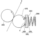
図2は、塗布ローラ1001、カウンターローラ1002および液体保持部材2001などの配置の一例を示す説明縦断側面図である。
カウンターローラ1002は、不図示の付勢手段によって塗布ローラ1001の周面に向けて付勢されており、塗布ローラ1001を図中、時計方向に回転させることにより、両ローラの間に塗布液を塗布すべき塗布媒体Pを挟持し得ると共に、塗布媒体Pを図中の矢印方向に搬送し得るようになっている。
Next, the elements of the respective parts constituting the liquid coating apparatus that has been outlined above will be described in more detail.
FIG. 2 is an explanatory longitudinal sectional side view showing an example of the arrangement of the
The
塗布ローラ1001の表面材質は弾性部材で構成されており、ゴム硬度40度以下のゴムが好適に用いられる。これにより、塗布媒体への塗布液の転写性および後述する当接部材2009でのシール性を両立させることができる。なお、ゴム硬度の測定方法は、「JIS K 6253 タイプA」に記載される通りである。本実施形態では、塗布ローラ1001の表面材質はゴム硬度30度のEPDM(エチレン−プロピレン−ジエンゴム)とし、表面粗さはRa1.6μmとし、直径22.19mmとした。カウンターローラ1002の材質はアルミニウムとし、表面は鏡面状に加工し、直径は22.19mmとした。
The surface material of the
また、液体保持部材2001は、バネ部材(押圧手段)2006の付勢力によって塗布ローラ1001の周面に対して付勢されて当接するとき、塗布ローラ1001による液体塗布領域全体にわたって延在する長尺な液体保持空間Sを形成するようになっている。この液体保持空間S内には、後述の液体供給経路3000から液体保持部材2001を介して塗布液が供給される。このとき、液体保持部材2001が以下のように構成されているため、塗布ローラ1001の停止状態において、液体保持空間Sから外方へ不用意に塗布液が漏出するのを防止することができる。
Further, when the
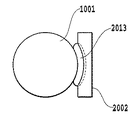
この液体保持部材2100の構成を、図3ないし図8に示す。
図3に示すように、液体保持部材2001は、空間形成基材2002と、この空間形成基材2002の一方の面に設けられた環状の当接部材2009とを有している。空間形成基材2002には、その中央部分における長手方向に沿って凹部2003が形成されている。そして、当接部材2009は、2つの直線部分(上縁部2010、下縁部2011)がこの凹部2003の上縁部に沿って固着され、また、左右の円弧状の部分(右縁部2013、左縁部2012)がそれぞれ凹部2003の一方の直線的な縁部から左右の底部を経て凹部2003の反対側の直線的な部分(下縁部2011)に至るように固着される。これにより、液体保持部材2001の当接部2009が塗布ローラ1001に当接したとき、塗布ローラの周面形状に沿った当接が可能となり、均一な圧力の当接を実現することができる。
The configuration of the liquid holding member 2100 is shown in FIGS.
As shown in FIG. 3, the
なお、本実施形態では、当接部材2009の材質はNBR(ニトリルブタジエンラバー)とし、硬度は共に70度、直径は3.5mmとした。
In the present embodiment, the material of the
上記のようにこの実施形態における液体保持部材は、継ぎ目のない一体に形成された当接部材2009が、バネ部材2006の付勢力によって塗布ローラ1001の外周面に隙間なく連続した状態で当接する。その結果、液体保持空間Sは、この当接部材2009と、空間形成基材の一面と、塗布ローラ1001の外周面とによる実質的に閉塞した空間となり、この空間に塗布液が保持される。そして、塗布ローラ1001の回転が停止した状態では、当接部材2009と塗布ローラ1001の外周面とは液密状態を維持し、液体が外部へと漏出するのを確実に防止することができる。一方、塗布ローラ1001が回転するときは、後述のように、塗布液は塗布ローラ1001の外周面と当接部材2009との間をすり抜けて、塗布ローラの外周面に層状に付着する。ここで、塗布ローラ1001の停止状態において、その外周面と当接部材2009とが密接状態にあるとは、上記のとおり、上記液体保持空間Sの内と外との間で液体を通さないことである。この場合、当接部材2009の当接状態としては、それが塗布ローラ1001の外周面に対し、直に接する状態の他、毛管力によって形成される液体の膜を解して上記外周面に当接する状態を含むものである。
As described above, in the liquid holding member in this embodiment, the abutting
また、当接部材2009の長手方向における左右両側部は、図3ないし図8に示すように、正面(図6)、平面(図3)および側面(図7、図8)のいずれの方向から見ても緩やかに湾曲する形状をなしている。このため、塗布ローラ1001に対し、比較的強い押圧力で当接部材2120を当接させても、当接部材2009の全体が略均一に弾性変形し、局所的に大きな歪みが生じることはない。このため、当接部材2009は図6ないし図8に示すように、隙間なく連続的に塗布ローラ1001の外周面に当接し、上記の実質的に閉塞した空間を形成することができる。
Further, the left and right side portions in the longitudinal direction of the abutting
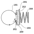
一方、空間形成基材2002には、図3ないし図5に示すように、当接部材2009に囲繞された領域内に、それぞれ空間形成基材2002を貫通する孔を有して構成される液体供給口2004および液体回収口2005が設けられている。これらは空間形成基材の背面側に突設された円筒状の連結部20041,20051にそれぞれ連通している。また、この連結部20041,20051は、後述の液体供給流路3000に連結されている。なお、この実施形態では、液体供給口2004が当接部材2009に囲繞された領域の一端部(図3では左端部)近傍に形成され、液体回収口2005が同領域の他端部(図3では右端部)近傍に設けられる。この液体供給口2004は、液体流路3000から供給される塗布液を前述の液体保持空間Sに供給し、液体回収口2005は液体保持空間S内の液体を液体流路3000へと流出させるためのものである。この液体の供給、流出を行うことにより、液体保持空間S内において、塗布液は上記の左端部から右端部へと流動する。
On the other hand, as shown in FIGS. 3 to 5, the space-forming
(塗布液流路)
図11は、前記塗布液供給手段の液体保持部材2001に連結される液体流路3000の概略構成を示す説明図である。
この液体流路3000は、液体保持部材2001を構成する空間形成基材2002の液体供給口2004と塗布液を貯蔵する貯蔵タンク3003とを連結する第1流路(供給流路)3001と、空間形成基材2002の液体回収口2005と前記貯蔵タンク3003とを連結する第2流路(回収流路)3002とを有する。この貯蔵タンク3003には、大気連通口3004が設けられている。また、この大気連通口には、大気との連通、遮断を切換える大気連通弁3005が設けられている。また、第1流路3001内には切換弁3006が設けられており、この切換弁3006によって第1流路3001と大気との連通、遮断が切換え可能となっている。さらに第2流路3002内には、本液体流路3000内で塗布液および空気を所望の方向へと強制的に流動させるためのポンプ3007が連結されている。この実施形態では、ポンプ3007は、第1流路3001から第2流路3002へ向かう方向(図中、矢印に示す方向)の液体の流れを発生させる。
(Coating solution flow path)
FIG. 11 is an explanatory diagram showing a schematic configuration of a
The
この実施形態において、第1流路3001および第2の流路3002は円管状のチューブによって形成されている。各チューブの端部に形成される開口部は、貯蔵タンク3003の底部もしくは底部に近い位置に配置され、貯蔵タンク3003内の塗布液を完全に消費し得るようになっている。
In this embodiment, the
また、この実施形態における切換弁3006は、第1流路3001と大気との連通、遮断を切換え得るものであれば、種々のものが適用可能であるが、ここでは図11に示すような三方弁を使用している。この三方弁3006は、互いに連通する3つのポートを有し、これらのポートのうち2つのポートを、第1流路3001における貯蔵タンク側チューブ3011と、液体保持部材側チューブ3012と、大気連通口3013の中のいずれか二つに選択的に連通させ得るものとなっている。そして、この三方弁3006の切換えにより、チューブ3011とチューブ3012とを連通させる連結状態と、チューブ3012と大気連通口3013とを連通させる連結状態とが選択的に切り換えられる。これにより、液体保持部材2001と塗布ローラ1001とによって形成される空間Sに対し、貯蔵タンク3003内の塗布液あるいは大気連通口3013から取り込まれる空気の何れかを選択して供給することが可能となる。なお、三方弁3006の切換えは、後述の制御部4000からの制御信号によって行われ、塗布液の充填、供給などが行われる。
(制御系)
図12は、本実施形態の液体塗布装置における制御系の概略構成を示すブロック図である。
図12において、4000は液体塗布装置全体を制御する制御手段としての制御部である。この制御部4000は、種々の演算、制御、判別などの処理動作を実行するCPU4001と、このCPU4001によって実行される、図13にて後述される処理などの制御プログラムなどを格納するROM4002と、CPU4001の処理動作中のデータや入力データなどを一時的に格納するRAM4003などを有する。このRAM4003には、塗布動作の停止時における塗布部材と液体保持部材との当接位置を示す情報も格納される。
(Control system)
FIG. 12 is a block diagram showing a schematic configuration of a control system in the liquid coating apparatus of the present embodiment.
In FIG. 12,
この制御部4000には、所定の指令あるいはデータなどを入力するキーボードあるいは各種スイッチなどを含む入力操作部4004、液体塗布装置の入力・設定状態などをはじめとする種々の表示を行う表示部4005、塗布媒体の位置や各部の動作状態などを検出するセンサなどを含む検出部4006、前記ローラ駆動モータ1004、ポンプ駆動モータ4009、大気連通弁3005および切換弁3006などがそれぞれ駆動回路4007,4008,4010,4011を介して接続されている。
The
(液体塗布動作シーケンス)
図13は、本実施形態の液体塗布装置の液体塗布に係わる処理手順を示すフローチャートである。以下、このフローチャートを参照して、液体塗布にかかる各工程を説明する。 すなわち、液体塗布装置に塗布開始準備の命令がくると、制御部4000は、図13に示すフローチャートに従って以下の塗布動作シーケンスを実行する。
(Liquid application operation sequence)
FIG. 13 is a flowchart showing a processing procedure related to liquid application of the liquid application apparatus of this embodiment. Hereinafter, with reference to this flowchart, each process concerning liquid application will be described. That is, when an instruction to start application is given to the liquid application apparatus, the
塗布ローラ停止位置の設定
ステップS1000では、後述の塗布ローラ1001の回転動作に先立って、前記塗布ローラ1001の回転方向における現在の停止位置、言い換えれば、塗布部材と液体保持部材との当接位置を示す情報を取得する。これにより、塗布ローラ1001の塗布面の中で、液体保持部材2001の当接部2009に当接する回転方向の位置を把握することができる。なおこのとき、塗布ローラ1001の回転位置が絶対的な回転位置で管理されている場合には、管理している絶対的な回転位置を示す情報を取得し、電源投入直後のように絶対的な回転位置が管理されていない状態であれば初期化した回転位置(例えば0リセットした場合は0)を示す情報を取得することになる。このような当接位置を示す情報は、RAM4003から読み出すことにより取得できる。
In the setting step S1000 of the application roller stop position , prior to the rotation operation of the
次にステップS1001で塗布ローラ1001の回転方向に対する停止位置の設定を行う。塗布ローラを停止させる位置としては、好ましくない位置が存在する。この位置としては、例えば、図15、図16、図17に示すような位置がある。
図15ないし図17において、塗布ローラ1001の塗布面上の黒丸印は、今までに当接部2009の上縁部2010および下縁部2011が当接していたニップ位置を示している。すなわち、この黒丸印は、前述のように初期位置を取得した際に、当接部2009の上縁部2010および下縁部2011が当接していた塗布ローラ1001上の位置(前回の当接位置)を示している。ここで、図15に示す塗布面の回転方向における位置は、前回の当接位置と同一の位置が当接部2009に当接するため、好ましくない。図16に示す塗布面の回転方向における位置は、前回の当接時において当接部2009の下縁部2011に当接していた当接位置が、当接部2009の上縁部2010に当接するため好ましくない。同様に、図17に示す塗布面の回転方向における位置は、前回の当接時において当接部2009の上縁部2010に当接していた当接位置が、下縁部2011に当接するため、好ましくない。つまり、前回の停止時における当接位置が、次の停止時において連続的に当接部2009に当接すると、当接部2009によって塗布面に形成された凹部(歪み)が塗布部材2009の弾性力によって復元し切れない状態で再び押圧されることとなり、歪みが蓄積されることとなる。
In step S1001, a stop position with respect to the rotation direction of the
15 to 17, black circles on the application surface of the
そこで、この第1の実施形態では、塗布動作終了後の塗布面の停止位置を、ステップS1001で取得した前回の停止位置から回転方向に沿って所定量だけ変位させた位置に設定し、これによって図15ないし図17に示すような位置関係になる頻度を低減し、塗布ローラの塗布面における歪みの蓄積を軽減し得るようになっている。この場合、今回の停止時において、前回の停止時における当接位置とは同じにならないよう設定するだけでなく、前回の停止時以前のN回(Nは2以上の整数)の停止時における各当接位置のいずれとも異なるよう、当接位置を制御することが好ましい。要するに、一度当接部2009に当接した塗布面の当接位置(例えば、位置1)が、再び当接部2009に当接するまでに、塗布動作終了後の停止位置として上記位置Aとは異なる複数の当接位置(例えば、位置2、位置3、位置4等)が介在するように、塗布動作終了後の停止位置を設定することが重要である。塗布動作と停止動作が繰り返される間に、塗布面に形成される歪みを塗布ローラ1001の弾性力および当接部2009との摺動によって復元させることができるからである。
Therefore, in the first embodiment, the stop position of the application surface after the application operation is finished is set to a position displaced from the previous stop position acquired in step S1001 by a predetermined amount along the rotation direction. The frequency of the positional relationship as shown in FIGS. 15 to 17 can be reduced, and the accumulation of distortion on the application surface of the application roller can be reduced. In this case, not only is it set not to be the same as the contact position at the time of the previous stop at the time of the current stop, but each time at the stop of N times (N is an integer of 2 or more) before the previous stop. The contact position is preferably controlled so as to be different from any of the contact positions. In short, the contact position (for example, position 1) of the application surface that has once contacted the
従って、塗布動作終了時の停止位置を前回の停止位置から回転方向に変位させる間隔(以下、変位量と称す)は、上縁部2010と下縁部2011との回転方向における設定間隔と同一もしくは1/2とならないように設定する必要がある。前記変位量を上縁部2010から下縁部2011に至る間隔と同一に設定した場合、塗布面を塗布動作と同一の回転方向(図中、矢印にて示す方向)に移動させると、その停止位置は図16に示す位置関係になる。また、逆方向に回転させると図17の位置関係になる。さらに、変位量を1/2に設定した場合には、塗布動作終了後の変位を2回繰り返すことで同様の状態となる。 また前記の変位量は、上縁部2010と下縁部2011との間の間隔の1/2未満には設定しないことが望ましい。これは、塗布動作と停止動作が少数回繰り返されただけで、前回の停止時において上縁部2010または下縁部2011に当接していた塗布面の当接位置が、再び下縁部2011または上縁部2010に当接してしまうためである。また、塗布ローラの周長の2分の1、3分の1、4分の1、3分の2、4分の3のような小さい整数で割った倍数に前記の変位量を設定することも避けるべきである。
Therefore, the interval at which the stop position at the end of the application operation is displaced in the rotational direction from the previous stop position (hereinafter referred to as the displacement amount) is the same as the set interval in the rotational direction between the
前記変位量の望ましい値としては、例えば、当接部2009の上縁部2010から下縁部2011に至る間隔の3分の2に設定とすることが考えられる。この場合の塗布ローラ1001の塗布面と当接部2009との当接位置を図18に示した。図18において塗布ローラ1001の周囲に表記してある丸で囲まれた数字は何回前の停止時に当接部2009に当接したかを示している。本実施形態の場合は10回前の停止時の当接位置が今回の停止時における当接位置と略同一位置になる。すなわち10回の停止を行わなければ停止の履歴のある当接位置には停止しないことになり、その間に十分に塗布面に形成された凹部(歪み)は回復する。
As a desirable value of the displacement amount, for example, it is conceivable to set the distance from the
以上のようにステップS1001では、塗布動作終了後における塗布面と液体保持部材との当接位置が塗布動作開始前の当接位置と異なるよう、塗布動作開始前の当接位置に基づいて塗布動作終了時の当接位置を設定するのである。なお、ここで、設定される当接位置を示す情報はRAM4003に記憶され、次回の塗布動作における当接位置の設定に利用される。
As described above, in step S1001, the application operation based on the contact position before the start of the application operation is performed so that the contact position between the application surface and the liquid holding member after the end of the application operation is different from the contact position before the start of the application operation. The contact position at the end is set. Here, the information indicating the set contact position is stored in the
充填工程
再び図13に戻り、ステップS1002では、前処理として前記塗布空間Sに対する塗布液の充填工程を実行する。この充填工程では、まず、貯蔵タンク3003の大気連通弁3005を大気に開放させると共に、切換弁(三方弁)3006を切り換えてチューブ3011とチューブ3012とを連通させ、ポンプ3007を一定時間駆動する。これにより、液体塗布空間Sおよび各流路3001,3002内に塗布液が充填されていない場合には、ポンプ3007によって内部の空気が貯留部へと送られて大気へと排出されると共に各部に塗布液が充填される。また、既に各部に塗布液が充填されている場合には、各部の塗布液が流動して適正な濃度および粘度の塗布液が供給される。この初期動作によって、塗布ローラ1001に対し塗布液が供給された状態となり、塗布媒体への塗布が可能となる。
Filling step Returning to FIG. 13 again, in step S1002, a coating solution filling step for the coating space S is performed as a pretreatment. In this filling step, first, the
塗布工程
ここで、塗布開始指令が入力されていると(ステップS1003)、再びポンプ3007が作動を開始すると共に(ステップS1004)、塗布ローラ1001が図1の矢印に示すように、時計周りに回転を開始する(ステップS1005)。この塗布ローラ1001の回転により、液体保持空間Sに充填された塗布液Lは、塗布ローラ1001に対する液体保持部材2001の当接部材2009の押圧力に抗して、塗布ローラ1001と当接部材2009の下縁部2011との間を摺り抜け、塗布ローラ1001の外周に層状態となって付着する。塗布ローラ1001に付着した塗布液Lは、塗布ローラ1001とカウンターローラ1002との当接部に送られる。
Application Step Here, when an application start command is input (step S1003), the
次いで、塗布媒体送給機構1006によって塗布ローラ1001とカウンターローラ1002との間に塗布媒体が搬送され、これらのローラの間に塗布媒体が挿入されるとともに、塗布ローラ1001とカウンターローラ1002の回転に伴い排紙部へ向けて搬送される(ステップS1006)。この搬送の間に、塗布ローラ1001の外周面に塗布された塗布液が、図9に示すように塗布ローラ1001から塗布媒体Pに転写される。なお、塗布ローラ1001とカウンターローラ1002との間に塗布媒体を供給する手段としては、上記の送給機構に限られないことは勿論であり、例えば、所定のガイド部材を補助的に用いる手差しによる手段を併せて用いてもよく、また、手差し手段を単独で用いる構成など、どのような手段を用いてもよい。
Next, the coating medium is transported between the
図9において、交差する斜線で表現した部分が塗布液Lを示している。なお、ここでは、塗布ローラ1001および塗布媒体Pにおける塗布液の層の厚みは、塗布時における塗布液Lの様子を明確に図示する上で、実際の厚みよりもかなり過大に表している。
In FIG. 9, a portion expressed by crossing oblique lines indicates the coating liquid L. Here, the thickness of the coating liquid layer on the
上記のようにして、塗布媒体Pの塗布された部分は塗布ローラ2001の搬送力により矢印方向に搬送されると共に、塗布媒体Pと塗布ローラ2001の接触部に塗布媒体Pの未塗布部分が搬送され、この動作を連続もしくは間欠的に行うことで塗布媒体全体に塗布液を塗布して行く。
As described above, the coated portion of the coating medium P is transported in the direction of the arrow by the transport force of the
ところで、図9においては、当接部材2009から摺り抜けて塗布ローラ2001に付着した塗布液Lの全てが塗布媒体Pに転写された理想的な塗布状態を示しているが、実際には、塗布ローラ1001に付着した塗布液Lの全てが塗布媒体Pに転写されるとは限らない。つまり、搬送される塗布媒体Pが塗布ローラ1001から離間する際、塗布液Lは、塗布ローラ1001にも付着し、塗布ローラ1001に塗布液Lが残留することが多い。この塗布ローラ1001における塗布液Lの残留量は、塗布媒体Pの材質及び表面の微小な凹凸の状態によっても異なるが、塗布媒体Pが普通紙の場合、塗布動作後も塗布ローラ1001の周面には塗布液Lが残留する。
FIG. 9 shows an ideal application state in which all of the coating liquid L that has passed through the
図24,図25,図14は、媒体Pが普通紙である場合における媒体の表面と塗布面での塗布過程を説明する説明図である。本図では液体を黒く塗りつぶしてある。 24, 25, and 14 are explanatory diagrams for explaining the coating process on the surface and the coating surface of the medium when the medium P is plain paper. In this figure, the liquid is painted black.
図24は塗布ローラ1001とカウンターローラ1002とのニップ部より上流側での状態を示している。同図において塗布ローラ1001の塗布面には液体が塗布面の表面の微細な凹凸をわずかに被うように液体が付着している。 図25は塗布ローラ1001とカウンターローラ1002とのニップ部での、媒体Pである普通紙の表面と塗布ローラ1001の塗布面の状態を示している。同図において媒体Pである普通紙の表面の凸部は塗布ローラ1001の塗布面と接触する。この接触した部分より液体が瞬時に媒体Pである普通紙の表面の繊維に浸透ないし吸着する。また塗布ローラ1001の塗布面には普通紙の表面の凸部と接触しない部分に付着した液体が残留する。
FIG. 24 shows a state upstream of the nip portion between the
図14は塗布ローラ1001とカウンターローラ1002とのニップ部より下流側での状態を示している。同図は媒体と塗布ローラ1001の塗布面が完全に離脱した状態である。塗布ローラ1001の塗布面には普通紙の表面の凸部と接触しない部分に残留した液体と接触部における液体も極微量ながら塗布面に残留する。
FIG. 14 shows a state downstream of the nip portion between the
この塗布ローラ1001に残留した塗布液は、塗布ローラ1001に対する液体保持部材2001の当接部材2009の押圧力に抗して、塗布ローラ1001と当接部材2009の上縁部2010との間を摺り抜けて液体保持空間S内に戻り、同空間S内に充填されている塗布液と混合される。
The application liquid remaining on the
また、この塗布液の戻し動作は、図10に示すように塗布媒体が存在しない状態で塗布ローラ1001を回転させた場合にも同様に行われる。すなわち、塗布ローラ1001を回転することで塗布ローラ1001の外周に付着した塗布液は、カウンターローラ1002と当接する部分(ニップ部)の間をすり抜ける。すり抜けた後は塗布ローラ1001側とカウンターローラ1002側とに塗布液が分離し、塗布ローラ1001に塗布液が残留する。そして、塗布ローラ1001側に付着した塗布液Lは当接部材2009の上縁部2010と塗布ローラ1001との間をすり抜けて液体保持空間S内に侵入し、同空間S内に充填されている塗布液に混合する。
Further, the returning operation of the coating liquid is performed in the same manner when the
終了工程
上記のようにして、塗布媒体への塗布動作が実行されると、次に塗布工程を終了して良いか否かの判断を行う(ステップS1007)。塗布工程を終了しない場合は、ステップS1006に戻り、塗布媒体の塗布が必要な部分全体に塗布工程を終了するまで塗布動作を繰り返す。
塗布工程を終了すると、塗布ローラ1001を停止させ(ステップS1008)、さらに、ポンプ3007の駆動を停止させ(ステップS1009)、待機時間の初期化として待機時間タイマーを0リセットする(S1010)。また、ステップS1008における塗布ローラ1001の回転停止位置は、前述のステップS1001で設定された停止位置とする。この後、ステップS1003へ移行し、塗布開始指令が入力されていれば、前述のステップS1003〜S1010の動作を繰り返す。また、ステップS1003で塗布開始指令が入力されていなければ、待機時間を管理するためにステップS1011に移行して待機時間タイマーによる計測時間が所定時間経過したか否かを判断する。この所定時間は60秒程度に設定することが適当である。ステップS1011において計測時間が所定時間未満であれば、ステップS1003へ移行して、塗布開始指令があるまでステップS1003とS1010の判断を繰り返し所定時間待機する。またステップS1011で所定時間が経過したと判断されれば、塗布空間Sおよび液体流路内の塗布液を回収する回収動作などの後処理を行い(ステップS1011)、塗布にかかる処理を終了する。
Ending Step When the coating operation on the coating medium is executed as described above, it is next determined whether or not the coating step can be finished (step S1007). If the application process is not completed, the process returns to step S1006, and the application operation is repeated until the application process is completed on the entire portion where application of the application medium is required.
When the application process is completed, the
なお、上記回収動作は、前記大気連通弁3005および切換弁3006を開放し、ポンプ3007を駆動することによって、塗布液を塗布液保持空間Sおよび第2流路3002内の塗布液を液体貯留タンク3003へと流入させることによって行う。この回収動作を行うことにより、液体保持空間Sからの塗布液の蒸発を防止することができる。また、回収動作後は大気連通弁3005を閉じ、切換弁3006を切換えて第1流路3001および大気連通口3013との連通を遮断することにより、貯蔵タンク3003を大気から遮断する。これにより、液体貯蔵タンク3003からの塗布液の蒸発を防止することができると共に、移動、運搬などにおいて装置の姿勢が傾いた場合にも塗布液が外部へ流出するのを防止することができる。
In the recovery operation, the
以上のようにこの第1の実施形態においては、液体保持部材2001の当接部2009に対し、塗布動作終了後の塗布ローラの停止位置を、塗布動作終了前の塗布ローラの停止位置から回転方向へと所定の変位量だけずらした位置(例えば、液体保持部材の上縁部と下縁部との間隔の2/3程度変位させた位置)に設定している。そして、塗布動作の終了工程では、先に設定した停止位置にて前記塗布ローラを停止させる。これにより、液体保持部材2001の当接部2009と塗布ローラ1001の塗布面とが同一位置で連続的に停止するのを禁止することができ、塗布面の同一位置に歪みが蓄積されるのを軽減することができる。
As described above, in the first embodiment, with respect to the
(第2実施形態)
次に、本発明の第2の実施形態を説明する。
第1の実施形態では、塗布動作直前のローラ停止期間と、その塗布動作直後のローラ停止期間とで塗布ローラ1001が連続して同一の位置に停止するのを禁止し、それによって塗布面の同一位置に歪みが蓄積されるのを防止した。しかし、この場合にも短い時間内で塗布動作の開始と終了とが繰り返されると、長期に塗布ローラが停止していた位置もしくはその付近で再び塗布ローラ1001が停止し、塗布面に歪みが蓄積される可能性もある。
そこで、この第2の実施形態では、液体保持部材2001の当接部2009に対し、塗布ローラ1001が同一位置で停止した時間(当接時間)の累積値であるニップ累積時間(当接累積時間)を計測し、その計測結果に従って、塗布ローラ1001の停止位置を設定している。なお、この累積時間を計測する累積時間計測手段は、CPU5001あるいは制御部4000に内臓されたタイマーによって実現される。
(Second Embodiment)
Next, a second embodiment of the present invention will be described.
In the first embodiment, the
Therefore, in the second embodiment, the accumulated nip time (accumulated contact time) that is a cumulative value of the time (contact time) when the
以下、図19に示すフローチャートに基づき、この第2の実施形態で実行される動作を説明する。
まず、ステップS2000では、第1実施形態のステップS1000と同様の処理を行い、塗布ローラ1001の現在の停止位置を取得する。
次にS2001でニップ累積時間を計測するタイマーを停止し、ステップS2002にて前記タイマー手段によって計測されたニップ累積時間を取得する。ステップS2002で取得したニップ累積時間が所定時間以上であった場合は、ステップS2005で第1実施形態のステップS1001と同様の処理によって停止位置の変更を行う。また、ニップ累積時間が所定時間未満の場合は、現在の停止位置を塗布動作後の停止位置として設定する。
The operation executed in the second embodiment will be described below based on the flowchart shown in FIG.
First, in step S2000, the same process as step S1000 of the first embodiment is performed, and the current stop position of the
In step S2001, the timer for measuring the accumulated nip time is stopped, and in step S2002, the accumulated nip time measured by the timer unit is acquired. If the accumulated nip time acquired in step S2002 is equal to or longer than the predetermined time, the stop position is changed in step S2005 by the same process as in step S1001 of the first embodiment. If the accumulated nip time is less than the predetermined time, the current stop position is set as the stop position after the coating operation.
次にステップS2006に移行する。ステップS2006は第1実施形態のステップS1002と同様の処理である。また、ステップS2007からステップS2012までの処理も第1実施形態のステップ1003からステップS1008までの処理と同一であるため、これらの説明は省略する。
終了工程におけるステップS2012で塗布ローラ1001を停止させた後、ステップS2013では前述のニップ累積時間が所定時間以上であるかを判断する。ここで、ニップ累積時間が所定時間以上である場合には、ニップ累積時間用のタイマーを0に更新する。このタイマーが0に変更される処理を行うことにより、塗布ローラ1001が前述の変更された停止位置で停止した状態にあることを認識することができると共に、塗布ローラ1001の停止位置が前回の停止位置から変更されたたことに伴ってニップ累積タイマーがリセットされたことを確認することができる。
Next, the process proceeds to step S2006. Step S2006 is the same process as step S1002 of the first embodiment. Further, the processing from step S2007 to step S2012 is also the same as the processing from
After the
次にステップS2015、S2016に移行するが、これらのステップにおける処理は、第1実施形態におけるステップ1009、ステップS1010の処理と同様であるため、説明を省略する。
この後、ステップS2007へ移行し、塗布開始指令が入力されていれば、前述のステップS2007〜S2016の動作を繰り返し、塗布開始指令が入力されていなければ、塗布開始指令の待機状態に移行する。ステップS2017、S2018も第1実施形態のステップ1011、ステップS1012の処理と同様であるため、説明を省略する。
最後にS2019に移行し、ニップ累積時間を管理するタイマーを現在設定されているニップ累積時間を継続して計測するためにタイマーを再始動する。
Next, the process proceeds to steps S2015 and S2016. Since the processes in these steps are the same as the processes in steps 1009 and S1010 in the first embodiment, description thereof will be omitted.
Thereafter, the process proceeds to step S2007, and if an application start command is input, the operations in steps S2007 to S2016 described above are repeated, and if the application start command is not input, the process shifts to a standby state for the application start command. Steps S2017 and S2018 are also the same as the processing of
Finally, the process proceeds to S2019, and a timer for managing the accumulated nip time is restarted in order to continuously measure the currently set accumulated nip time.
上述のように、この第2の実施形態では、塗布ローラ1001の停止時間を累積した時間が所定時間を超えない限り、塗布ローラ1001の停止位置を変更せず、塗布ローラ1001を同一の位置に停止させるようになっている。このため、短時間に塗布動作の開始と停止を繰り返す場合にも、塗布ローラ1001が、先に長期にわたって停止していた位置、もしくはその付近に停止するのを回避することができる。また、ステップS2013の判断基準となる前記の所定時間は、媒体への液体の塗布などに塗布ローラ1001の歪が問題にならない程度の時間に設定する。例えば塗布ローラの材質がシリコーンゴムである場合、150時間程度が適当である。
As described above, in the second embodiment, the
(他の実施形態)
上述の実施形態では塗布ローラ1001の塗布面において液体保持部材2001の当接部2009の上縁部2010もしくは下縁部2011との当接位置が繰り返し同じ場所にならないように考慮して、停止位置を所定量移動した位置になるように制御している。しかしながら、この停止位置の移動量は、液体保持部材2001と塗布ローラ1001との当接位置だけでなく、塗布ローラ1001とカウンターローラ1002との当接位置を考慮してもよい。
(Other embodiments)
In the above-described embodiment, the stop position is determined so that the contact position of the
また、塗布ローラ1001における塗布面と液体保持部材2001との回転方向における相対的な位置関係は、塗布ローラの回転角に応じてロータリ・エンコーダから出力されるパルス数のカウント値によって管理したり、駆動源がステッピングモータである場合は、モータのステップ数によって管理したりすることが適当である。 また前述した実施形態では、塗布部材と液体保持部材とが常に同一位置で停止しないように、各停止時における停止位置の設定を停止前に予め行うものとした。しかしながら、液体塗布部材の停止位置の設定は、液体塗布部材の停止直後に行うことも可能である。すなわち、液体塗布部材の停止直後に、今回の停止位置が前回の停止位置と同じであるかを判断し、前回の停止位置と同一の停止位置である場合には、前回と異なる位置に停止させるようにしてもよい。また不揮発性メモリなどを用いて複数回の停止位置履歴を記憶しておき、停止直後にその今回の停止位置が、停止履歴に記憶されている停止位置と同一であるか否かを判断し、同一位置である場合には、停止履歴に記憶されていない位置に停止させるようにしてもよい。
The relative positional relationship between the application surface of the
なお、本発明は、液体保持部材と塗布部材との当接位置を適宜変更することを目的とするものであるが、上記実施形態では液体保持部材が塗布部材の回転移動方向において定位置に存在する構成を前提としているため、塗布部材の停止位置のみを管理することによって液体保持部材と塗布部材との当接位置を管理することができる。但し、塗布部材と液体保持部材との当接位置は、液体保持部材を塗布部材の回転方向へと移動させることによっても変更可能である。従って、この場合には、液体保持部材と塗布部材の双方の位置情報に基づき液体保持部材と塗布部材との当接位置を管理する必要がある。 The present invention aims to change the contact position between the liquid holding member and the coating member as appropriate, but in the above embodiment, the liquid holding member exists at a fixed position in the rotational movement direction of the coating member. Therefore, the contact position between the liquid holding member and the application member can be managed by managing only the stop position of the application member. However, the contact position between the application member and the liquid holding member can also be changed by moving the liquid holding member in the rotation direction of the application member. Therefore, in this case, it is necessary to manage the contact position between the liquid holding member and the application member based on the position information of both the liquid holding member and the application member.
(インクジェット記録装置の実施形態)
図20は、上述の液体塗布装置とほぼ同様の構成を有した塗布機構を備えたインクジェット記録装置1の概略構成を示す図である。
このインクジェット記録装置1には、複数枚の記録媒体Pを積載する給送トレイ2が設けられており、半月形状の分離ローラ3が、給送トレイに積載された記録媒体Pを1枚づつ分離して搬送経路に給送する。搬送経路中には、上記液体塗布機構の液体塗布手段を構成する塗布ローラ1001およびカウンターローラ1002が配置されている。給送トレイ2から給送された記録媒体Pは、両ローラ1001,1002の間に送られる。塗布ローラ1001はローラ駆動モータの回転によって図20において時計周り方向に回転し、記録媒体Pを搬送しながら塗布液を記録媒体Pの記録面に塗布する。塗布液が塗布された記録媒体Pは、搬送ローラ4とピンチローラ5との間に送られる。そして、搬送ローラ4が、図中、反時計周り方向へと回転することによって、記録媒体Pはプラテン6の上を搬送され、記録手段を構成する記録ヘッド7に対向する位置へと移動する。記録ヘッド7は所定数のインク吐出用のノズルを配設したインクジェット記録ヘッドである。この記録ヘッド7は図の紙面と垂直方向に走査する間に、記録データに従ってノズルから記録媒体Pの記録面に対してインク滴を吐出して記録を行う。この記録動作と搬送ローラ4による所定量の搬送動作とを交互に繰り返しながら、記録媒体に画像を形成して行く。この画像形成動作とともに、記録媒体の搬送路において記録ヘッドの走査領域の後流側に設けられた排紙ローラ8と排紙拍車9とが記録媒体Pを挟持し、排紙ローラ8の回転によって排紙トレイ10上に排出する。
(Embodiment of inkjet recording apparatus)
FIG. 20 is a diagram showing a schematic configuration of the
The
なお、このインクジェット記録装置としては、インクを吐出するノズルを記録媒体の最大幅に亘って配設した長尺な記録ヘッドを用いて記録動作を行ういわゆるフルライン型のインクジェット記録装置を構成することも可能である。 As the ink jet recording apparatus, a so-called full line type ink jet recording apparatus that performs a recording operation using a long recording head in which nozzles for ejecting ink are arranged over the maximum width of the recording medium is configured. Is also possible.
また、この実施形態で用いる塗布液は、顔料を色材とするインクで記録した際に顔料の凝集を早める処理液である。この実施形態では、塗布液として処理液を用いることにより、この処理液とこの処理液が塗布された記録媒体に吐出されるインクの色材である顔料を反応させて顔料の凝集を早めさせる。そして、この不溶化により、記録濃度の向上を図ることができる。さらに、ブリーディングの軽減または防止が可能となる。なお、インクジェット記録装置において用いる塗布液としては、上述の例に限られないことは勿論である。 The coating liquid used in this embodiment is a processing liquid that accelerates the aggregation of the pigment when recording with the ink using the pigment as the color material. In this embodiment, by using the treatment liquid as the coating liquid, the pigment that is the color material of the ink discharged onto the recording medium coated with the treatment liquid is reacted to accelerate the aggregation of the pigment. This insolubilization can improve the recording density. Furthermore, bleeding can be reduced or prevented. Needless to say, the coating liquid used in the ink jet recording apparatus is not limited to the above example.
図21は、上述したインクジェット記録装置の要部を示す斜視図である。同図に示すように、給送トレイ2の一端の上方に塗布機構100が設けられ、この塗布機構より上部で、給送トレイ2の中央部上方に記録ヘッド7などを備えた記録機構が設けられる。
FIG. 21 is a perspective view showing a main part of the above-described ink jet recording apparatus. As shown in the figure, a
図22は、上述したインクジェット記録装置の制御系の概略構成を示すブロック図である。同図において、液体塗布機構の要素であるローラ駆動機構1004、ポンプ駆動モータ4009、および大気連通弁のアクチュエータ3005は、前述した液体塗布装置とで説明したものと同様の要素である。
FIG. 22 is a block diagram showing a schematic configuration of a control system of the above-described ink jet recording apparatus. In the drawing, a
CPU5001は、図23にて後述する処理手順のプログラムに従い、塗布機構の各要素の駆動を制御するとともに、記録機構にかかるLFモータ5013、CRモータ5015、および記録ヘッド7の駆動を、それぞれの駆動回路5012、5014、5016を介して制御する。すなわち、LFモータ5013の駆動によって搬送ローラ4などを回転させ、また、CRモータの駆動によって記録ヘッド7を搭載したキャリッジを移動させる。さらに、記録ヘッドのノズルからインクを吐出させる制御を行う。
The
図23は、本実施形態のインクジェット記録装置における液体塗布およびそれに伴う記録動作の手順を示すフローチャートである。
同図において、ステップS3003、S3007、S3008を除くステップS3000〜S3013の処理は、図13に示した、ステップS1003、ステップS1007を除くステップS1000〜S1012の処理と同様である。
FIG. 23 is a flowchart showing a procedure of liquid application and a recording operation associated therewith in the ink jet recording apparatus of the present embodiment.
In the figure, the processing of steps S3000 to S3013 excluding steps S3003, S3007, and S3008 is the same as the processing of steps S1000 to S1012 excluding steps S1003 and S1007 shown in FIG.
図23に示すように、本実施形態では、記録開始の指令があると(ステップS3003)、ポンプ作動などの一連の液体塗布動作を行う(ステップS3004〜S3006)。そして、記録媒体の液体塗布が必要な部分に液体を塗布する。 As shown in FIG. 23, in this embodiment, when there is an instruction to start recording (step S3003), a series of liquid application operations such as pump operation are performed (steps S3004 to S3006). Then, a liquid is applied to a portion of the recording medium that requires liquid application.
この塗布工程の後、必要な部分に塗布液が塗布された記録媒体に対して、記録動作を行う(ステップS3007)。すなわち、搬送ローラ4によって所定量ずつ搬送される記録媒体Pに対して記録ヘッド7を走査させ、この走査の間に記録データに応じてノズルからインクを吐出することにより記録媒体にインクを付着させてドットを形成する。この付着するインクは塗布液と反応するため、濃度向上や滲みの防止が可能となる。以上の記録媒体の搬送と記録ヘッドの走査を繰り返すことにより、記録媒体Pに対して記録がなされ、記録を終了した記録媒体は排紙トレイ10上に排出される。ステップS3008で記録が終了したと判断すると、ステップS3009以降の処理を行い、本処理を終了する。
After this coating process, a recording operation is performed on the recording medium in which the coating liquid is coated on a necessary portion (step S3007). That is, the recording head 7 is scanned with respect to the recording medium P conveyed by a predetermined amount by the conveying roller 4, and ink is attached to the recording medium by ejecting ink from the nozzles according to the recording data during this scanning. To form dots. Since this adhering ink reacts with the coating liquid, it is possible to improve the density and prevent bleeding. By repeating the above-described conveyance of the recording medium and scanning of the recording head, recording is performed on the recording medium P, and the recording medium that has finished recording is discharged onto the
なお、本実施形態では、記録媒体に対する液体塗布に伴い、その塗布が終了した部分に対して順次記録を行うものである。すなわち、塗布ローラから記録ヘッドへ至る搬送路の長さが記録媒体の長さよりも短く、記録媒体上の液体の塗布がなされた部分が記録ヘッドによる走査領域に至るときに、記録媒体の他の部分に塗布機構によって塗布が行われる形態であり、記録媒体の所定量の搬送ごとに、記録媒体の異なる部分で、順次、液体塗布と記録がなされていく。しかし、本発明の適用する上で、別の形態として、特許文献5に記載されるように、1つの記録媒体に対する塗布が完了してから記録を行うものであってもよい。 In the present embodiment, recording is sequentially performed on a portion where the application has been completed as the liquid application is performed on the recording medium. That is, when the length of the conveyance path from the coating roller to the recording head is shorter than the length of the recording medium, and the portion where the liquid is applied on the recording medium reaches the scanning area by the recording head, This is a form in which application is performed on the portion by the application mechanism, and liquid application and recording are sequentially performed in different portions of the recording medium every time a predetermined amount of the recording medium is conveyed. However, when the present invention is applied, as another embodiment, as described in Patent Document 5, recording may be performed after application to one recording medium is completed.
また、本発明における記録装置においては、液体塗布機構によって、蛍光増白剤を含有する液体を塗布することにより、媒体の白色度を向上させることが可能である。また、別の塗布液として、塗布媒体のカール(媒体が湾曲形状となる現象)を抑制する成分を含有する液体を用いることも可能である。前記液体塗布後の記録手段は、インクジェット記録方式に限らず、熱転写方式、電子写真方式などの記録方式を採るものでも効果を得ることができる。 In the recording apparatus of the present invention, the whiteness of the medium can be improved by applying a liquid containing a fluorescent brightening agent by a liquid application mechanism. Further, as another coating liquid, a liquid containing a component that suppresses curling of the coating medium (a phenomenon in which the medium becomes a curved shape) can be used. The recording means after applying the liquid is not limited to the ink jet recording method, but the recording means such as the thermal transfer method and the electrophotographic method can also be effective.
また、銀塩写真方式の記録装置において、記録前に、感光剤を塗布してもよい。 In a silver halide photographic recording apparatus, a photosensitive agent may be applied before recording.
1 インクジェット記録装置
2 給紙トレイ
3 分離ローラ
4 搬送ローラ
5 ピンチローラ
6 プラテン
7 記録部
8 排紙ローラ
9 排紙拍車
10 排紙トレイ
100 液体塗布装置
1001 塗布ローラ
1002 カウンターローラ
1003 ローラ駆動機構
1004 ローラ駆動モータ
1005 動力伝達機構
2001 液体保持部材
2002 空間形成部材
2003 凹部
2004 液体供給口
2005 液体回収口
2009 当接部材
2010 上縁部
2011 下縁部
2012 左側縁部
2013 右側縁部
3000 液体流路
3001 第1流路
3002 第2流路
3003 貯蔵タンク
3004 大気連通口
3005 大気連通弁
3006 切換弁
3007 ポンプ
4000 制御部
4001 CPU
4002 ROM
4003 RAM
4004 入力操作部
4005 表示部
4006 検出部
4007 ローラ駆動モータの駆動回路
4008 ポンプ駆動モータの駆動回路
4009 ポンプ駆動モータ
4010 大気連通弁の駆動回路
4011 切換弁の駆動回路
DESCRIPTION OF
4002 ROM
4003 RAM
4004
Claims (8)
前記塗布動作終了後における前記塗布部材と前記液体保持部材との当接位置が前記塗布動作開始前の当接位置と異なるように、前記塗布動作開始前の当接位置に基づいて前記塗布動作終了後の当接位置を設定する当接位置設定手段と、
を備えたことを特徴とする液体塗布装置。 Has a coating member having an elastically deformable application surface for applying liquid to medium body and a liquid holding member that holds the liquid in the liquid holding space formed in contact with the coated surface of the coating member, before Liquid application means for performing an application operation of applying the liquid to the medium via the application surface by rotating the application surface of the application member;
End of the application operation based on the contact position before the start of the application operation so that the contact position between the application member and the liquid holding member after the application operation ends is different from the contact position before the start of the application operation. Contact position setting means for setting a subsequent contact position;
A liquid coating apparatus comprising:
前記当接位置設定手段は、前記塗布動作開始前における前記塗布面の停止時間が所定時間以上であるとき、前記塗布動作終了後における前記当接位置を、前記塗布動作開始前における当接位置に対して異ならせることを特徴とする請求項1または2に記載の液体塗布装置。 It further comprises time measuring means for measuring the stop time of the application surface,
The contact position setting means sets the contact position after the end of the application operation to the contact position before the start of the application operation when the stop time of the application surface before the start of the application operation is a predetermined time or more. The liquid application apparatus according to claim 1, wherein the liquid application apparatus is different from the liquid application apparatus.
前記当接位置設定手段は、前記塗布動作開始前の当接位置を示す情報を前記記憶部から取得し、前記取得した情報に基づいて前記塗布動作終了後の当接位置を設定し、当該設定した当接位置を示す情報を前記記憶部に記憶することを特徴とする請求項1に記載の液体塗布装置。 A storage unit that stores information indicating a contact position when the application operation is stopped;
The contact position setting means acquires information indicating the contact position before the start of the application operation from the storage unit, sets the contact position after the end of the application operation based on the acquired information, and sets the setting The liquid application apparatus according to claim 1, wherein information indicating the contact position is stored in the storage unit.
前記塗布動作終了後における前記塗布部材と前記液体保持部材との当接位置を、前記塗布動作開始前における前記塗布部材と前記液体保持部材との当接位置に対して異ならせることを特徴とする液体塗布装置の制御方法。 An application member having an elastically deformable application surface for applying a liquid to a medium; and a liquid holding member for holding the liquid in a liquid holding space formed in contact with the application surface of the application member. A control method of a liquid application apparatus that performs an application operation of applying the liquid to the medium via the application surface by rotating the application surface of the application member with respect to a holding member,
The contact position between the application member and the liquid holding member after the application operation is finished is different from the contact position between the application member and the liquid holding member before the application operation is started. Control method of liquid coating apparatus.
前記液体塗布手段により液体が塗布された記録媒体に対して記録を行う記録手段と、
前記塗布動作終了後における前記塗布部材と前記液体保持部材との当接位置が、前記塗布動作開始前における当接位置と異なるように、前記塗布動作開始前の当接位置に基づいて前記塗布動作終了後の当接位置を設定する当接位置設定手段と、
を備えたことを特徴とする記録装置。 Has a coating member having an elastically deformable application surface for applying liquid to a record medium and a liquid holding member for holding the liquid to the liquid holding space formed in contact with the coated surface of the coating member, the A liquid application means for performing an application operation of applying the liquid to the recording medium through the application surface by rotating the application surface of the application member;
Recording means for recording on a recording medium coated with liquid by the liquid applying means;
The application operation based on the contact position before the start of the application operation so that the contact position between the application member and the liquid holding member after the application operation is different from the contact position before the start of the application operation. Contact position setting means for setting the contact position after the end;
A recording apparatus comprising:
前記記録媒体に前記液体を塗布する弾性変形可能な塗布面を有する塗布部材と、前記塗布部材の塗布面に当接して形成される液体保持空間に液体を保持する液体保持部材とを有し、前記塗布部材の塗布面を回転させることによって前記塗布面を介して前記液体を前記記録媒体に塗布する塗布動作を行う液体塗布手段と、
前記液体塗布手段により液体が塗布された記録媒体に対してインクを吐出するためのインクジェットヘッドと、
前記塗布動作終了後における前記塗布部材と前記液体保持部材との当接位置を、前記塗布動作開始前における当接位置に対して異ならせる当接位置変更手段と、
を備えることを特徴とする記録装置。 A recording apparatus that performs recording on a recording medium using a liquid that agglomerates ink and a coloring material in the ink,
An application member having an elastically deformable application surface for applying the liquid to the recording medium; and a liquid holding member for holding the liquid in a liquid holding space formed in contact with the application surface of the application member; Liquid application means for performing an application operation of applying the liquid to the recording medium via the application surface by rotating the application surface of the application member;
An inkjet head for ejecting ink to a recording medium coated with liquid by the liquid coating means;
Contact position changing means for making the contact position between the application member and the liquid holding member after the application operation end different from the contact position before the application operation starts;
A recording apparatus comprising:
Priority Applications (2)
| Application Number | Priority Date | Filing Date | Title |
|---|---|---|---|
| JP2005168568A JP4480159B2 (en) | 2005-06-08 | 2005-06-08 | Liquid applicator, recording device |
| US11/445,030 US7536974B2 (en) | 2005-06-08 | 2006-06-01 | Liquid applying apparatus and printing apparatus |
Applications Claiming Priority (1)
| Application Number | Priority Date | Filing Date | Title |
|---|---|---|---|
| JP2005168568A JP4480159B2 (en) | 2005-06-08 | 2005-06-08 | Liquid applicator, recording device |
Publications (3)
| Publication Number | Publication Date |
|---|---|
| JP2006341182A JP2006341182A (en) | 2006-12-21 |
| JP2006341182A5 JP2006341182A5 (en) | 2008-02-14 |
| JP4480159B2 true JP4480159B2 (en) | 2010-06-16 |
Family
ID=37523742
Family Applications (1)
| Application Number | Title | Priority Date | Filing Date |
|---|---|---|---|
| JP2005168568A Expired - Fee Related JP4480159B2 (en) | 2005-06-08 | 2005-06-08 | Liquid applicator, recording device |
Country Status (2)
| Country | Link |
|---|---|
| US (1) | US7536974B2 (en) |
| JP (1) | JP4480159B2 (en) |
Families Citing this family (2)
| Publication number | Priority date | Publication date | Assignee | Title |
|---|---|---|---|---|
| JP5196557B2 (en) * | 2008-08-13 | 2013-05-15 | 富士フイルム株式会社 | Image forming apparatus |
| US20130177716A1 (en) * | 2012-01-11 | 2013-07-11 | D. Edward Wheatley | Method of manufacturing a substrate having a textured surface |
Citations (2)
| Publication number | Priority date | Publication date | Assignee | Title |
|---|---|---|---|---|
| JP2003093940A (en) * | 2001-07-19 | 2003-04-02 | Canon Inc | Liquid coating device adaptive to ink-recorded medium and image forming apparatus having the same |
| JP2004054149A (en) * | 2002-07-24 | 2004-02-19 | Ricoh Co Ltd | Fixing device |
Family Cites Families (8)
| Publication number | Priority date | Publication date | Assignee | Title |
|---|---|---|---|---|
| US3952700A (en) * | 1970-11-09 | 1976-04-27 | Xerox Corporation | Liquid applicator |
| JP3184050B2 (en) | 1994-08-24 | 2001-07-09 | 富士機械工業株式会社 | Ink supply device for gravure printing press |
| JPH0872227A (en) | 1994-09-02 | 1996-03-19 | Canon Inc | Image forming apparatus |
| JP3640369B2 (en) * | 1997-09-04 | 2005-04-20 | 株式会社リコー | Image recording method, image recording apparatus, and image recording promoting liquid |
| US6183079B1 (en) * | 1998-06-11 | 2001-02-06 | Lexmark International, Inc. | Coating apparatus for use in an ink jet printer |
| JP2001070858A (en) | 1999-07-07 | 2001-03-21 | Canon Inc | Paint coater and coating method |
| JP4025004B2 (en) | 2000-09-22 | 2007-12-19 | 株式会社リコー | Image recording device |
| JP2003025559A (en) * | 2001-07-19 | 2003-01-29 | Canon Inc | Liquid coater and image recorder |
-
2005
- 2005-06-08 JP JP2005168568A patent/JP4480159B2/en not_active Expired - Fee Related
-
2006
- 2006-06-01 US US11/445,030 patent/US7536974B2/en not_active Expired - Fee Related
Patent Citations (2)
| Publication number | Priority date | Publication date | Assignee | Title |
|---|---|---|---|---|
| JP2003093940A (en) * | 2001-07-19 | 2003-04-02 | Canon Inc | Liquid coating device adaptive to ink-recorded medium and image forming apparatus having the same |
| JP2004054149A (en) * | 2002-07-24 | 2004-02-19 | Ricoh Co Ltd | Fixing device |
Also Published As
| Publication number | Publication date |
|---|---|
| US20060279618A1 (en) | 2006-12-14 |
| US7536974B2 (en) | 2009-05-26 |
| JP2006341182A (en) | 2006-12-21 |
Similar Documents
| Publication | Publication Date | Title |
|---|---|---|
| JP4498148B2 (en) | Liquid applicator, recording device | |
| JP4480166B2 (en) | Liquid coating apparatus and inkjet recording apparatus | |
| JP4617383B2 (en) | Inkjet recording device | |
| JP4669347B2 (en) | Liquid coating apparatus and inkjet recording apparatus | |
| US7270409B2 (en) | Liquid applying apparatus and ink jet printing apparatus | |
| JP4533275B2 (en) | Liquid coating apparatus and inkjet recording apparatus | |
| US7461932B2 (en) | Ink jet printing apparatus for preventing degradation of liquid application member | |
| JP2007117807A (en) | Liquid coating device, and recording apparatus | |
| JP4480159B2 (en) | Liquid applicator, recording device | |
| JP4677246B2 (en) | Inkjet recording device | |
| JP4384086B2 (en) | Liquid coating apparatus and inkjet recording apparatus | |
| JP2007117806A (en) | Liquid coating device and recording apparatus | |
| JP4642360B2 (en) | Liquid applicator, recording device | |
| JP4355662B2 (en) | Inkjet recording device | |
| JP4906460B2 (en) | Liquid applicator | |
| JP4683641B2 (en) | Inkjet recording device | |
| JP4508978B2 (en) | Liquid coating apparatus and inkjet recording apparatus | |
| JP2005254803A (en) | Liquid applying apparatus and inkjet recording apparatus | |
| JP2005224701A (en) | Liquid coating device and inkjet recording device |
Legal Events
| Date | Code | Title | Description |
|---|---|---|---|
| A521 | Request for written amendment filed |
Free format text: JAPANESE INTERMEDIATE CODE: A523 Effective date: 20071220 |
|
| A621 | Written request for application examination |
Free format text: JAPANESE INTERMEDIATE CODE: A621 Effective date: 20071220 |
|
| TRDD | Decision of grant or rejection written | ||
| A01 | Written decision to grant a patent or to grant a registration (utility model) |
Free format text: JAPANESE INTERMEDIATE CODE: A01 Effective date: 20100312 |
|
| A01 | Written decision to grant a patent or to grant a registration (utility model) |
Free format text: JAPANESE INTERMEDIATE CODE: A01 |
|
| A61 | First payment of annual fees (during grant procedure) |
Free format text: JAPANESE INTERMEDIATE CODE: A61 Effective date: 20100315 |
|
| FPAY | Renewal fee payment (event date is renewal date of database) |
Free format text: PAYMENT UNTIL: 20130326 Year of fee payment: 3 |
|
| R150 | Certificate of patent or registration of utility model |
Free format text: JAPANESE INTERMEDIATE CODE: R150 |
|
| FPAY | Renewal fee payment (event date is renewal date of database) |
Free format text: PAYMENT UNTIL: 20140326 Year of fee payment: 4 |
|
| LAPS | Cancellation because of no payment of annual fees |