JP5053206B2 - Method of forming quartz glass material using mold material - Google Patents
Method of forming quartz glass material using mold material Download PDFInfo
- Publication number
- JP5053206B2 JP5053206B2 JP2008213596A JP2008213596A JP5053206B2 JP 5053206 B2 JP5053206 B2 JP 5053206B2 JP 2008213596 A JP2008213596 A JP 2008213596A JP 2008213596 A JP2008213596 A JP 2008213596A JP 5053206 B2 JP5053206 B2 JP 5053206B2
- Authority
- JP
- Japan
- Prior art keywords
- quartz glass
- glass material
- mold
- mold material
- alumina
- Prior art date
- Legal status (The legal status is an assumption and is not a legal conclusion. Google has not performed a legal analysis and makes no representation as to the accuracy of the status listed.)
- Active
Links
- 239000000463 material Substances 0.000 title claims description 236
- VYPSYNLAJGMNEJ-UHFFFAOYSA-N Silicium dioxide Chemical compound O=[Si]=O VYPSYNLAJGMNEJ-UHFFFAOYSA-N 0.000 title claims description 147
- 238000000034 method Methods 0.000 title claims description 56
- PNEYBMLMFCGWSK-UHFFFAOYSA-N aluminium oxide Inorganic materials [O-2].[O-2].[O-2].[Al+3].[Al+3] PNEYBMLMFCGWSK-UHFFFAOYSA-N 0.000 claims description 85
- 238000010438 heat treatment Methods 0.000 claims description 35
- 238000000465 moulding Methods 0.000 claims description 26
- 239000007789 gas Substances 0.000 claims description 25
- 239000002002 slurry Substances 0.000 claims description 24
- 239000000843 powder Substances 0.000 claims description 23
- OKTJSMMVPCPJKN-UHFFFAOYSA-N Carbon Chemical compound [C] OKTJSMMVPCPJKN-UHFFFAOYSA-N 0.000 claims description 17
- 239000011521 glass Substances 0.000 claims description 17
- 229910052799 carbon Inorganic materials 0.000 claims description 12
- 238000002844 melting Methods 0.000 claims description 12
- 239000002245 particle Substances 0.000 claims description 11
- 239000011575 calcium Substances 0.000 claims description 10
- 239000011734 sodium Substances 0.000 claims description 10
- XLYOFNOQVPJJNP-UHFFFAOYSA-N water Substances O XLYOFNOQVPJJNP-UHFFFAOYSA-N 0.000 claims description 10
- IJGRMHOSHXDMSA-UHFFFAOYSA-N Atomic nitrogen Chemical compound N#N IJGRMHOSHXDMSA-UHFFFAOYSA-N 0.000 claims description 9
- 230000008018 melting Effects 0.000 claims description 9
- XEEYBQQBJWHFJM-UHFFFAOYSA-N Iron Chemical compound [Fe] XEEYBQQBJWHFJM-UHFFFAOYSA-N 0.000 claims description 8
- 239000011261 inert gas Substances 0.000 claims description 8
- 229910052791 calcium Inorganic materials 0.000 claims description 6
- 239000002270 dispersing agent Substances 0.000 claims description 6
- 238000002156 mixing Methods 0.000 claims description 6
- 229910052708 sodium Inorganic materials 0.000 claims description 6
- 239000004372 Polyvinyl alcohol Substances 0.000 claims description 5
- 229920002451 polyvinyl alcohol Polymers 0.000 claims description 5
- 238000005507 spraying Methods 0.000 claims description 5
- XKRFYHLGVUSROY-UHFFFAOYSA-N Argon Chemical compound [Ar] XKRFYHLGVUSROY-UHFFFAOYSA-N 0.000 claims description 4
- 229910052742 iron Inorganic materials 0.000 claims description 4
- 239000001307 helium Substances 0.000 claims description 3
- 229910052734 helium Inorganic materials 0.000 claims description 3
- SWQJXJOGLNCZEY-UHFFFAOYSA-N helium atom Chemical compound [He] SWQJXJOGLNCZEY-UHFFFAOYSA-N 0.000 claims description 3
- 229910052754 neon Inorganic materials 0.000 claims description 3
- GKAOGPIIYCISHV-UHFFFAOYSA-N neon atom Chemical compound [Ne] GKAOGPIIYCISHV-UHFFFAOYSA-N 0.000 claims description 3
- 229910018072 Al 2 O 3 Inorganic materials 0.000 claims description 2
- OYPRJOBELJOOCE-UHFFFAOYSA-N Calcium Chemical compound [Ca] OYPRJOBELJOOCE-UHFFFAOYSA-N 0.000 claims description 2
- DGAQECJNVWCQMB-PUAWFVPOSA-M Ilexoside XXIX Chemical compound C[C@@H]1CC[C@@]2(CC[C@@]3(C(=CC[C@H]4[C@]3(CC[C@@H]5[C@@]4(CC[C@@H](C5(C)C)OS(=O)(=O)[O-])C)C)[C@@H]2[C@]1(C)O)C)C(=O)O[C@H]6[C@@H]([C@H]([C@@H]([C@H](O6)CO)O)O)O.[Na+] DGAQECJNVWCQMB-PUAWFVPOSA-M 0.000 claims description 2
- 229910052786 argon Inorganic materials 0.000 claims description 2
- 238000010304 firing Methods 0.000 claims description 2
- 238000007493 shaping process Methods 0.000 claims 4
- UGFAIRIUMAVXCW-UHFFFAOYSA-N Carbon monoxide Chemical compound [O+]#[C-] UGFAIRIUMAVXCW-UHFFFAOYSA-N 0.000 description 8
- 229910002091 carbon monoxide Inorganic materials 0.000 description 8
- 238000004519 manufacturing process Methods 0.000 description 8
- 229910001873 dinitrogen Inorganic materials 0.000 description 7
- 230000002093 peripheral effect Effects 0.000 description 7
- HBMJWWWQQXIZIP-UHFFFAOYSA-N silicon carbide Chemical compound [Si+]#[C-] HBMJWWWQQXIZIP-UHFFFAOYSA-N 0.000 description 6
- 239000005350 fused silica glass Substances 0.000 description 5
- 239000010439 graphite Substances 0.000 description 5
- 229910002804 graphite Inorganic materials 0.000 description 5
- 238000000227 grinding Methods 0.000 description 5
- 229910010271 silicon carbide Inorganic materials 0.000 description 5
- 238000003754 machining Methods 0.000 description 4
- 239000010453 quartz Substances 0.000 description 4
- 239000011247 coating layer Substances 0.000 description 3
- 230000000052 comparative effect Effects 0.000 description 3
- 230000000694 effects Effects 0.000 description 3
- 238000002474 experimental method Methods 0.000 description 3
- 230000003287 optical effect Effects 0.000 description 3
- 239000000470 constituent Substances 0.000 description 2
- 238000001035 drying Methods 0.000 description 2
- 238000005530 etching Methods 0.000 description 2
- 239000000155 melt Substances 0.000 description 2
- 150000001282 organosilanes Chemical class 0.000 description 2
- RMAQACBXLXPBSY-UHFFFAOYSA-N silicic acid Chemical compound O[Si](O)(O)O RMAQACBXLXPBSY-UHFFFAOYSA-N 0.000 description 2
- 239000000377 silicon dioxide Substances 0.000 description 2
- 229910004298 SiO 2 Inorganic materials 0.000 description 1
- 238000001354 calcination Methods 0.000 description 1
- 239000011248 coating agent Substances 0.000 description 1
- 238000000576 coating method Methods 0.000 description 1
- 238000004891 communication Methods 0.000 description 1
- 238000005520 cutting process Methods 0.000 description 1
- 238000010586 diagram Methods 0.000 description 1
- 239000006185 dispersion Substances 0.000 description 1
- 239000012535 impurity Substances 0.000 description 1
- 239000010410 layer Substances 0.000 description 1
- 239000004973 liquid crystal related substance Substances 0.000 description 1
- 239000012528 membrane Substances 0.000 description 1
- 239000000203 mixture Substances 0.000 description 1
- 239000004065 semiconductor Substances 0.000 description 1
- 239000007921 spray Substances 0.000 description 1
- 239000000126 substance Substances 0.000 description 1
- 229910021642 ultra pure water Inorganic materials 0.000 description 1
- 239000012498 ultrapure water Substances 0.000 description 1
Images


Description
本発明は、型材を用いた石英ガラス材料の成形方法に関し、さらに詳細には、カーボン製の型材内の石英ガラス材料を加熱溶融してガラス製品の概形を成形するようにした型材を用いた石英ガラス材料の成形方法に関する。 The present invention relates to a method for molding a quartz glass material using a mold material. More specifically, the present invention uses a mold material in which a quartz glass material in a carbon mold material is heated and melted to mold a rough shape of a glass product. The present invention relates to a method for forming a quartz glass material.
近年、ガラス製品、特に、石英ガラスよりなるガラス製品(以下、単に「石英ガラス製品」と適宜に称する。)は、光学レンズなどの光学機器に限らず、その耐久性や化学的安定性などの利点を生かし、半導体製造用治具、液晶ディスプレイ(LCD:Liquid Crystal Display)パネル製造用フォトマスクあるいは光通信用の精密部品などに広く用いられている。 In recent years, glass products, particularly glass products made of quartz glass (hereinafter simply referred to as “quartz glass products” as appropriate) are not limited to optical devices such as optical lenses, but have durability and chemical stability. Taking advantage of the advantages, it is widely used in semiconductor manufacturing jigs, liquid crystal display (LCD) panel manufacturing photomasks or precision components for optical communication.
一般に、こうした石英ガラス製品の製造プロセスとしては、エッチングや研削加工などのような、加工対象物から不要な領域を除去する除去工程を主に用いるプロセスが採用されていた。 In general, as a manufacturing process of such a quartz glass product, a process mainly using a removal process for removing an unnecessary region from an object to be processed, such as etching or grinding, has been adopted.
しかしながら、エッチングによる製造プロセスは、加工対象物の表面の比較的微細な加工に限定されるため、それにより得られるガラス製品が限定されてしまうという問題点があった。
However, since the manufacturing process by etching is limited to relatively fine processing of the surface of the object to be processed, there is a problem that the glass product obtained thereby is limited.
また、研削加工による製造プロセスは、加工対象物を少量ずつ研削して所望の形状に加工するため、加工時間が多くかかるとともに、加工対象物から不要な部分を全て研削してしまうため、最終的に加工された石英ガラス製品の重量に比べより大きな石英ガラス材料の重量が必要となり、製造効率や製造コスト上で問題点が指摘されていた。 In addition, since the manufacturing process by grinding is performed to grind the processing object little by little to process it into a desired shape, it takes a lot of processing time and all unnecessary parts are ground from the processing object. As compared with the weight of the quartz glass product processed in this way, a larger weight of the quartz glass material is required, and problems have been pointed out in terms of production efficiency and production cost.
こうした問題点を解決するための手段として、型材を用いてガラス製品の概形を成形し、成形された成形体に研削などの機械加工を施してガラス製品を作製する手法が知られている。以下、型材を用いてガラス製品の概形を成形する方法について説明する。
As means for solving such problems, a technique is known in which a rough shape of a glass product is formed using a mold material, and a machined process such as grinding is performed on the formed molded body to produce a glass product. Hereinafter, a method for forming a rough shape of a glass product using a mold material will be described.
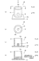
即ち、図1(a)には石英ガラス材料が載置された型材の概略構成説明図が示されており、図1(b)には図1(a)のA矢視図が示されており、図1(c)には図1(a)のB−B断面図が示されており、図1(d)には加熱溶融後の石英ガラス材料と型材の断面図が示されている。 That is, FIG. 1 (a) shows a schematic configuration explanatory diagram of a mold member on which a quartz glass material is placed, and FIG. 1 (b) shows a view as seen from an arrow A in FIG. 1 (a). 1 (c) shows a cross-sectional view taken along the line B-B of FIG. 1 (a), and FIG. 1 (d) shows a cross-sectional view of the quartz glass material and the mold material after heating and melting. .
この石英ガラス材料の成形に用いる型材10は、底板12と、底板12の上面12aに配置されるとともに所望の内径を有する円筒形状の外筒14とを有して構成されている。こうした、底板12および外筒14はカーボン製である。なお、符号14aは、外筒14の内周面を示している。
The
以上の構成において、石英ガラス材料を石英ガラス製品の概形に成形するには、まず、外筒14内の底板12の上面12aに石英バルクまたはインゴットといった石英ガラス材料16を載置し、石英ガラス材料16が載置された型材10を電気炉などの加熱装置(図示せず。)により、例えば、窒素ガスなどの不活性ガス雰囲気下において、加熱温度1500〜2000℃で加熱する。
In the above configuration, in order to form the quartz glass material into a rough shape of the quartz glass product, first, the
このように、加熱装置内で型材10が加熱温度1500〜2000℃で加熱されることにより、型材10中に載置された石英ガラス材料16は加熱溶融され、加熱溶融された石英ガラス材料16は、図1(d)に示されるように、外筒14の内径と同一の寸法の円柱形状の成形体として成形される。
Thus, when the
こうして成形された石英ガラス材料16は、研削などの機械加工工程を経て所望の形状の石英ガラス製品として製作される。
The
なお、上記において、加熱装置により加熱されて石英ガラス材料16が加熱溶融される際の加熱温度を1500〜2000℃としたが、より詳細には、1750〜1900℃とすることが好ましい。
In the above description, the heating temperature when the
これは、石英ガラス材料16を加熱溶融する加熱温度が1500℃未満のときは、石英ガラスが高粘性を有するために石英ガラス材料16を変形させにくく、型材10中で石英ガラス材料16が求める形状に成形されない恐れがあるからであり、また、石英ガラス材料16の加熱温度が2000℃を超えるときには、石英ガラス材料16が分解して型材10の各構成部材の構成材料であるカーボンと激しく反応してしまう恐れがあるからである。
This is because when the heating temperature at which the
しかしながら、こうした型材10においては、石英ガラス材料16を型材10中で高温で加熱溶融するために、加熱溶融した石英ガラス材料16と型材10とが接している面において、型材10の各構成部材の構成材料であるカーボンと石英ガラス材料16とが反応して一酸化炭素ガスを発生したり、石英ガラス材料16中に含有される水分により水蒸気を発生してしまい、発生した一酸化炭素ガスおよび水蒸気は加熱溶融されて低粘度となった石英ガラス材料16中に巻き込まれ、こうしたガスを気泡として混入した状態で加熱溶融された石英ガラス材料16が冷却され成形体として成形されるので、成形体が研削などの機械加工工程において加工される際に、所望の形状に加工できなくなるという問題が生じていた。
However, in such a
さらに、加熱溶融時に熱膨張係数が異なる石英ガラス材料16と型材10の各構成部材の構成材料であるカーボンとが反応融着するため、加熱溶融後の石英ガラス材料16たる成形体を型材10から取り出す際にクラックが発生してしまい、成形体を切削などの機械加工工程において加工される際に、所望の形状に加工できなくなるという問題も発生していた。
Furthermore, since the
こうした問題点を解決するための手法として、特許文献1または特許文献2には、石英ガラス材料が配置されたグラファイト製容器に炭化珪素の被膜を形成し、加熱溶融された石英ガラス材料とグラファイト製容器が直接接触することがないようにして、一酸化炭素ガスを発生させないようにした技術が開示されている。
As a technique for solving such a problem, Patent Document 1 or Patent Document 2 discloses that a silicon carbide film is formed on a graphite container in which a quartz glass material is arranged, and the fused quartz glass material and graphite are heated. A technique is disclosed in which carbon monoxide gas is not generated by preventing the container from coming into direct contact.
また、特許文献3には、黒鉛モールドに複数の貫通孔を設け、黒鉛モールドの内周面にカーボンフェルトなどから構成される多孔質層を設けることにより、黒鉛モールド中においてシリカ粉末が蒸発溶融しやすくなり、集合気泡を除去できるようにした技術が開示されている。 In Patent Document 3, a plurality of through holes are provided in a graphite mold, and a porous layer made of carbon felt or the like is provided on the inner peripheral surface of the graphite mold, whereby silica powder evaporates and melts in the graphite mold. A technique that facilitates the removal of the collective bubbles is disclosed.
しかしながら、特許文献1には炭化珪素の具体的な被覆方法が開示されておらず、また、特許文献2に開示された技術によれば、炭化珪素の被膜を形成するために、有機シランからシリカゾルを形成し、形成したシリカゾルに有機シランと炭化珪素とのモル比を考慮して高純度のβ炭化珪素微粉末を加えてシリカゾル−炭化珪素として作製しなければならず、シリカゾル−炭化珪素を作製する作業が繁雑となっていた。
However, Patent Document 1 does not disclose a specific method for coating silicon carbide, and according to the technique disclosed in Patent Document 2, in order to form a silicon carbide film, silica sol is formed from organosilane. In view of the molar ratio of organosilane and silicon carbide, a high-purity β silicon carbide fine powder must be added to the formed silica sol to produce silica sol-silicon carbide. The work to do was complicated.
また、特許文献3に開示された技術は、炭化珪素粉末を加熱溶融する際に発生したSiO2ガスを単に外部に逃がすようにしたものであって、石英ガラス材料と炭素との反応により発生する一酸化炭素ガスや、加熱溶融する対象物が石英バルクもしくはインゴットなどのときに石英バルクやインゴット中に含有する水分により発生するガスについては検討されていなかった。
本発明は、上記したような従来に技術の有する種々の問題点に鑑みてなされたものであり、その目的とするところは、簡単な作業により型材における加熱溶融された石英ガラス材料が接する面に被覆層(以下、加熱溶融された石英ガラス材料が接する面に形成された被覆層を「離型材」と称することとする。)を形成するようにした型材を用いた石英ガラス材料の成形方法を提供しようとするものである。 The present invention has been made in view of the various problems of the prior art as described above, and the object of the present invention is to bring the heated and fused quartz glass material into contact with the surface of the mold material by a simple operation. A method for molding a quartz glass material using a mold material for forming a coating layer (hereinafter, a coating layer formed on a surface in contact with a heated and fused quartz glass material is referred to as a “release material”). It is something to be offered .
また、本発明の目的とするところは、加熱溶融された石英ガラス材料中に一酸化炭素ガスや水蒸気などによる気泡を混入することなしに石英ガラス材料を所定の形状に成形するようにした型材を用いた石英ガラス材料の成形方法を提供しようとするものである。 Further, the object of the present invention is to provide a mold material in which the quartz glass material is molded into a predetermined shape without mixing bubbles due to carbon monoxide gas or water vapor into the heated and melted quartz glass material. An object of the present invention is to provide a method for forming the quartz glass material used.
また、本発明の目的とするところは、クラックを発生することなしに石英ガラス材料を所定の形状に成形するようにした型材を用いた石英ガラス材料の成形方法を提供しようとするものである。 Also, an object of the present invention is to provide a method for forming a quartz glass material using a mold material in which the quartz glass material is formed into a predetermined shape without generating cracks.
上記目的を達成するために、本発明は、型材において加熱溶融された石英ガラス材料の接する面に対して離型材として、アルミナ膜を形成するようにしたものである。 In order to achieve the above object, according to the present invention, an alumina film is formed as a mold release material on the surface of the mold material that contacts the fused and fused quartz glass material.
従って、本発明によれば、一酸化炭素ガスの発生を抑制し、石英ガラスのバルクから発生する水蒸気を加熱溶融後の石英ガラス材料たる成形体中に巻き込むことがなくなる。 Therefore, according to this invention, generation | occurrence | production of carbon monoxide gas is suppressed and the water vapor | steam generate | occur | produced from the bulk of quartz glass does not get involved in the molded object which is the quartz glass material after heat-melting.
また、本発明によれば、加熱溶融後の石英ガラス材料たる成形体がカーボン製の型材と接しないため、成形体を型材から剥離する際にクラックが発生することがなくなる。 Further, according to the present invention, since the molded body, which is the quartz glass material after being heated and melted, does not come into contact with the carbon mold material, cracks do not occur when the molded body is peeled from the mold material.
即ち、本発明のうち請求項1に記載の発明は、型材中で石英ガラス材料を加熱溶融してガラス製品の概形を成形する型材を用いた石英ガラス材料の成形方法において、加熱溶融される石英ガラス材料の接する面にアルミナ(Al2O3)スラリーを塗布した後に乾燥させてアルミナ膜を形成したカーボン製の型材を用い、上記型材中に石英ガラス材料を載置して、上記型材中で石英ガラス材料を加熱溶融してガラス製品の概形を成形するようにしたものである。
That is, the invention described in claim 1 of the present invention is heated and melted in a method for forming a quartz glass material using a mold material that heats and melts a quartz glass material in a mold material to form a rough shape of a glass product. Using a carbon mold material in which an alumina (Al 2 O 3 ) slurry is applied to the surface in contact with the quartz glass material and then dried to form an alumina film, the quartz glass material is placed in the mold material, The quartz glass material is heated and melted to form a rough shape of the glass product.
また、本発明のうち請求項2に記載の発明は、本発明のうち請求項1に記載の発明において、上記アルミナスラリーは、アルミナ粉末と水とを混合してスラリー化するようにしたものである。 The invention described in claim 2 of the present invention is the invention described in claim 1 of the present invention, wherein the alumina slurry is formed by mixing alumina powder and water to form a slurry. is there.
また、本発明のうち請求項3に記載の発明は、本発明のうち請求項2に記載の発明において、上記アルミナスラリーは、分散剤としてポリビニルアルコールを0.1重量%以上30重量%以下添加するようにしたものである。 The invention according to claim 3 of the present invention is the invention according to claim 2 of the present invention, wherein the alumina slurry is added with 0.1 to 30% by weight of polyvinyl alcohol as a dispersant. It is what you do.
また、本発明のうち請求項4に記載の発明は、本発明のうち請求項2または3のいずれか1項に記載の発明において、上記アルミナ粉末は、鉄(Fe)の含有量が0.1ppm以上8ppm以下、かつ、ナトリウム(Na)の含有量が0.1ppm以上5ppm以下、かつ、カルシウム(Ca)の含有量が0.1ppm以上4ppm以下で、FeとNaとCaとを含むようにしたものである。 The invention according to claim 4 of the present invention is the invention according to any one of claims 2 or 3 of the present invention, wherein the alumina powder has an iron (Fe) content of 0.00. 1 ppm to 8 ppm, sodium (Na) content is 0.1 ppm to 5 ppm, and calcium (Ca) content is 0.1 ppm to 4 ppm so that Fe, Na, and Ca are included. It is a thing.
また、本発明のうち請求項5に記載の発明は、本発明のうち請求項2、3または4のいずれか1項に記載の発明において、上記アルミナ粉末は、平均粒径が0.1μm以上0.5μm以下であるようにしたものである。 Further, the invention according to claim 5 of the present invention is the invention according to any one of claims 2, 3 or 4 of the present invention, wherein the alumina powder has an average particle size of 0.1 μm or more. It is made to be 0.5 μm or less.
また、本発明のうち請求項6に記載の発明は、本発明のうち請求項1、2、3、4または5のいずれか1項に記載の発明において、上記アルミナスラリーは、刷毛もしくはスプレーコーティングにより塗布するようにしたものである。 The invention according to claim 6 of the present invention is the invention according to any one of claims 1, 2, 3, 4 or 5 of the present invention, wherein the alumina slurry is a brush or a spray coating. It is made to apply | coat by.
また、本発明のうち請求項7に記載の発明は、本発明のうち請求項1、2、3、4、5または6のいずれか1項に記載の発明において、上記アルミナ膜を加熱温度1500〜2000℃で焼成するようにしたものである。 The invention according to claim 7 of the present invention is the invention according to any one of claims 1, 2, 3, 4, 5 or 6 of the present invention, wherein the alumina film is heated at a heating temperature of 1500. It is fired at ˜2000 ° C.
また、本発明のうち請求項8に記載の発明は、本発明のうち請求項1、2、3、4、5または6のいずれか1項に記載の発明において、上記アルミナ膜を加熱温度1750〜1900℃で焼成するようにしたものである。 The invention according to claim 8 of the present invention is the invention according to any one of claims 1, 2, 3, 4, 5 or 6 of the present invention, wherein the alumina film is heated to a temperature of 1750. It is made to bake at -1900 degreeC.
また、本発明のうち請求項9に記載の発明は、本発明のうち請求項7または8のいずれか1項に記載の発明において、上記アルミナ膜の焼成は、不活性ガス雰囲気または真空中で行うようにしたものである。 The invention described in Claim 9 is the invention according to any one of claims 7 or 8 of the present invention, calcination of the alumina film, an inert gas atmosphere or in a vacuum It is what I do.
また、本発明のうち請求項10に記載の発明は、本発明のうち請求項1、2、3、4、5、6、7、8または9のいずれか1項に記載の発明において、上記石英ガラス材料を加熱溶融する際の加熱温度は、1500〜2000℃であるようにしたものである。 The invention according to claim 10 of the present invention is the invention according to any one of claims 1, 2, 3, 4, 5, 6, 7, 8 or 9 of the present invention. The heating temperature when the quartz glass material is melted by heating is set to 1500 to 2000 ° C.
また、本発明のうち請求項11に記載の発明は、本発明のうち請求項1、2、3、4、5、6、7、8または9のいずれか1項に記載の発明において、上記石英ガラス材料を加熱溶融する際の加熱温度は、1750〜1900℃であるようにしたものである。 The invention according to claim 11 of the present invention is the invention according to any one of claims 1, 2, 3, 4, 5, 6, 7, 8 or 9 of the present invention. The heating temperature when the quartz glass material is heated and melted is 1750 to 1900 ° C.
また、本発明のうち請求項12に記載の発明は、本発明のうち請求項1、2、3、4、5、6、7、8、9、10または11のいずれか1項に記載の発明において、上記石英ガラス材料の加熱溶融を不活性ガス雰囲気または真空中で行うようにしたものである。
The invention described in
また、本発明のうち請求項13に記載の発明は、本発明のうち請求項9または12のいずれか1項に記載の発明において、上記不活性ガスは、窒素(N2)ガス、アルゴン(Ar)ガス、ネオン(Ne)ガス、ヘリウム(He)ガスあるいはこれらの混合ガスであるようにしたものである。
The invention described in claim 13 of the present invention is the invention described in any one of
本発明は、以上説明したように構成されているので、簡単な作業により離型材を形成することができるという優れた効果を奏する。 Since the present invention is configured as described above, there is an excellent effect that the release material can be formed by a simple operation.
また、本発明は、以上説明したように構成されているので、加熱溶融された石英ガラス材料中に一酸化炭素ガスや水蒸気などによる気泡を混入することなしに石英ガラス材料を所定の形状に成形することができるという優れた効果を奏する。 In addition, since the present invention is configured as described above, the quartz glass material is molded into a predetermined shape without mixing bubbles due to carbon monoxide gas or water vapor into the heated and melted quartz glass material. There is an excellent effect of being able to.
また、本発明は、以上説明したように構成されているので、クラックを発生することなしに石英ガラス材料を所定の形状に成形することができるという優れた効果を奏する。 In addition, since the present invention is configured as described above, there is an excellent effect that the quartz glass material can be formed into a predetermined shape without generating cracks.
以下、添付の図面を参照しながら、本発明による型材を用いた石英ガラス材料の成形方法の実施の形態の一例について詳細に説明するものとする。 Hereinafter, an example of an embodiment of a method for forming a quartz glass material using a mold material according to the present invention will be described in detail with reference to the accompanying drawings.
なお、以下の説明においては、図1を参照しながら説明した従来の技術による石英ガラス材料の成形方法に用いられる型材と同一または相当する構成については、上記において用いた符号と同一の符号を用いて示すことにより、その詳細な構成ならびに作用の説明は適宜に省略することとする。 In the following description, the same reference numerals as those used above are used for the same or corresponding components as those used in the quartz glass material molding method according to the prior art described with reference to FIG. Therefore, the detailed configuration and description of the operation will be omitted as appropriate.
本発明による型材を用いた石英ガラス材料の成形方法は、型材において加熱溶融された石英ガラス材料の接する面に対して離型材として、アルミナ膜からなる被覆層を形成するようにしたものである。
In the method for molding a quartz glass material using a mold material according to the present invention, a coating layer made of an alumina film is formed as a mold release material on the surface of the mold material that contacts the fused and melted quartz glass material.
以下、図2および図3を参照しながら、離型材としてアルミナ膜を形成する場合について、詳細に説明することとする。 Hereinafter, the case where an alumina film is formed as a release material will be described in detail with reference to FIGS. 2 and 3.
ここで、図2には、離型材としてアルミナ膜20を形成した型材10と石英ガラス材料16との断面図が示されている。
Here, FIG. 2 shows a cross-sectional view of the
型材10において、加熱溶融された石英ガラス材料16が接する面、つまり、底板12の上面12aおよび外筒14の内周面14aには、アルミナ膜20が形成されている。
In the
このアルミナ膜20を形成するには、アルミナスラリーを作製し、作製したアルミナスラリーを刷毛やスプレーなどにより底板12の上面12aおよび外筒14の内周面14aに対して塗布する。
In order to form the
こうして塗布されたアルミナスラリーを乾燥してアルミナ膜20が形成され、形成されたアルミナ膜20が型材10において離型材として使用される。
The alumina slurry thus applied is dried to form an
ここで、アルミナスラリーは、所定の粒径を有するアルミナ粉末を所定の割合だけ純水に混ぜ、分散機もしくは粉砕機により混合して作製する。
Here, the alumina slurry is prepared by mixing alumina powder having a predetermined particle diameter with pure water in a predetermined ratio and mixing with a disperser or a pulverizer.
この際、アルミナスラリー中のアルミナ粉末の粒径が5μmを超える大きさのものでは成膜し難くなるため、0.1μm以上5μm以下の適度な細かさを有していることが好ましく、アルミナスラリー中のアルミナ粉末の粒径が0.1μm以上0.5μm以下であることが特に好ましい。 At this time, since it is difficult to form a film if the particle size of the alumina powder in the alumina slurry exceeds 5 μm, the alumina slurry preferably has an appropriate fineness of 0.1 μm or more and 5 μm or less. It is particularly preferable that the particle diameter of the alumina powder is 0.1 μm or more and 0.5 μm or less.
即ち、アルミナ粉末を用いたアルミナスラリーから離型材たるアルミナ膜20を形成する場合に、アルミナ粉末の粒径が小さいほど緻密な膜を得ることができる。
That is, when the
しかしながら、アルミナ粉末の粒径が小さ過ぎると、アルミナ粉末のかさ密度が低下し、取り扱いが困難になる。 However, if the particle size of the alumina powder is too small, the bulk density of the alumina powder is lowered and handling becomes difficult.
従って、粒径が0.1μm以上5μm以下、さらに、粒径が0.1μm以上0.5μm以下のアルミナ粉末を用いることが望ましい。 Therefore, it is desirable to use an alumina powder having a particle size of 0.1 μm or more and 5 μm or less, and further a particle size of 0.1 μm or more and 0.5 μm or less.
なお、離型材たるアルミナ膜20の密度が高いほど、離型性も向上する。
Note that the higher the density of the
さらに、こうしたアルミナスラリーに使用されるアルミナ粉末としては、できるだけ高純度のものを用いることが望ましい。
Furthermore, it is desirable to use as high a purity as possible as the alumina powder used in such an alumina slurry.
なお、一般に、アルミナ粉末には、不純物として、Fe、NaならびにCaが含まれており、これらFe、NaならびにCaは石英に拡散しやすく、離型材にこれらがふくまれると、離型を阻害する要因となる。 In general, alumina powder contains Fe, Na, and Ca as impurities, and these Fe, Na, and Ca are likely to diffuse into quartz, and if these are included in a release material, release is hindered. It becomes a factor.
しかしながら、Feの含有量が0.1ppm以上8ppm以下、かつ、Naの含有量が0.1ppm以上5ppm以下、かつ、Caの含有量が0.1ppm以上4ppm以下で、あるならば、実用上問題のない離型材たるアルミナ膜20を形成することができる。
However, if the Fe content is 0.1 ppm to 8 ppm, the Na content is 0.1 ppm to 5 ppm, and the Ca content is 0.1 ppm to 4 ppm, there is a practical problem. An
なお、本実施の形態においては、Feの含有量が0.1ppm以上8ppm以下、かつ、Naの含有量が0.1ppm以上5ppm以下、かつ、Caの含有量が0.1ppm以上4ppm以下で不純物を含むアルミナ粉末を用いた。 In this embodiment, the Fe content is 0.1 ppm to 8 ppm, the Na content is 0.1 ppm to 5 ppm, and the Ca content is 0.1 ppm to 4 ppm. An alumina powder containing was used.
具体的には、平均粒径が0.2μmのアルミナ粉末をアルミナ粉末が30wt%(重量%)となるようにして超純水に混ぜ、この混合液に分散剤として1wt%のポリビニルアルコールを添加した後に、16時間かけてボールミルにより混合してアルミナスラリーを作製する。
Specifically, alumina powder having an average particle size of 0.2 μm is mixed with ultrapure water so that the alumina powder is 30 wt% (wt%), and 1 wt% polyvinyl alcohol is added as a dispersant to the mixture. After that, the slurry is mixed by a ball mill for 16 hours to prepare an alumina slurry.
ここで、離型材が離型性を十分に発揮するためには、離型材として均質なアルミナ膜20を形成することが重要である。
Here, in order for the release material to fully exhibit the release properties, it is important to form a
均質なアルミナ膜20を得るためには、アルミナスラリーを均一にする必要があるが、アルミナ粉末を水の中に分散させる際に分散剤を用いることにより、アルミナ粉末の分散の均一性を向上させることができる。
In order to obtain the
なお、上記した例においては、分散剤として1wt%のポリビニルアルコールを添加した場合について示したが、分散剤として添加するポリビニルアルコールは0.1wt%以上30wt%以下添加することが好ましい。 In the above example, the case where 1 wt% polyvinyl alcohol is added as a dispersant is shown, but it is preferable to add 0.1 wt% or more and 30 wt% or less of polyvinyl alcohol added as a dispersant.
そして、作製されたアルミナスラリーをスプレーコーティング法により、底板12の上面12aおよび外筒14の内周面14aに塗布し、100℃で2時間かけて乾燥してアルミナ膜20を形成する。
Then, the prepared alumina slurry is applied to the
なお、こうしたスラリーを使用したスプレーコーティング法は、従来より周知の技術であるためその詳細な説明は省略する。 In addition, since the spray coating method using such a slurry is a conventionally well-known technique, the detailed description is abbreviate | omitted.
ここで、乾燥して得られたアルミナ膜20は、この状態でも離型材として用いることが可能であるが、こうしたアルミナ膜20をさらに焼結したものを離型材として用いるようにしてもよい。
Here, the
即ち、乾燥して得られたアルミナ膜20が形成された底板12および外筒14を電気炉などの加熱装置内に入れて、窒素ガス雰囲気下において、加熱温度1500〜2000℃、好ましくは、1750〜1900℃の範囲で焼成して、アルミナ膜20を焼成する。
That is, the
このようにしてアルミナ膜20を焼成することにより、型材10とアルミナ膜20との密着性が向上するとともに、型材10と加熱溶融された石英ガラス材料16たる成形体との剥離性も向上するようになる。
By firing the
なお、こうした焼成されたアルミナ膜20の膜厚は、例えば、数百μm程度から数mmとすることが好ましい。
Note that the thickness of the
こうして、離型材としてアルミナ膜20を形成した型材10内に石英ガラス材料16を載置し、型材10を加熱装置内に配置して、型材10を当該加熱装置により、例えば、窒素ガスなどの不活性ガス雰囲気下において、加熱温度1500〜2000℃で加熱することにより、型材10中に載置された石英ガラス材料16は加熱溶融され、加熱溶融された石英ガラス材料16は、外筒14の内径と同一の寸法の円柱形状の成形体として成形される。
Thus, the
このとき、型材10における加熱溶融された石英ガラス材料16の接する面、つまり、底板12の上面12aおよび外筒14の内周面14aにはアルミナ膜20が形成されているので、加熱溶融後の石英ガラス材料16たる成形体がカーボン製の型材と接することがなくなり、カーボンと石英ガラスとの反応により発生する一酸化炭素ガスは発生しなくなるため、加熱溶融後の石英ガラス材料16たる成形体に気泡の巻き込みを生じなくなる。
At this time, since the
さらに、加熱溶融されて冷却された石英ガラス材料16たる成形体を型材10から剥離することが容易になり、クラックの発生が抑制される。
Furthermore, it becomes easy to peel off the molded body, which is the
次に、上記した手法によりアルミナ膜を形成した型材を用いて石英ガラス材料を成形する際における気泡の巻き込みおよびクラックの有無について、本願発明者が行った実験の結果について説明する。
Next, the results of experiments conducted by the inventors of the present application will be described with respect to the presence of bubbles and cracks when a quartz glass material is molded using a mold material on which an alumina film is formed by the above-described method.
この実験においては、重量16.5〜18.6kgの石英ガラス材料16を離型材としてアルミナ膜20を形成した型材10内に配置し、加熱装置として電気炉を用い、その内部圧力を0.03MPa、窒素ガス雰囲気下において加熱温度1800℃で石英ガラス材料16を加熱溶融して、加熱溶融後の石英ガラス材料16たる成形体においてクラックの有無および気泡の巻き込みの有無について確認した。
In this experiment, a
ここで、離型材としてのアルミナ膜20は、平均粒径0.2μmのアルミナ粉末が30重量%で混合されたアルミナスラリーを、スプレーコーティング法により塗布した後、100℃で2時間かけて乾燥させて形成され、形成されたアルミナ膜を窒素ガス雰囲気下において加熱温度1800℃で焼成して形成した。
Here, the
また、比較のため、重さ15.8〜23.7kgの石英ガラス材料16を離型材を設けていない型材10内に配置し、上記条件と同一の条件、即ち、加熱装置として電気炉を用い、その内部圧力を0.03MPa、窒素ガス雰囲気下において加熱温度1800℃で石英ガラス材料16を加熱溶融して、加熱溶融後の石英ガラス材料16たる成形体においてクラックの有無および気泡の巻き込みの有無について確認した。
For comparison, a
図3(a)(b)には、本願発明者による実験の結果が示されている。ここで、図3(a)の実施例1−1〜1−6には、石英ガラス材料16を離型材としてアルミナ膜20が形成された型材10内で加熱溶融したときに成形される加熱溶融後の石英ガラス材料16たる成形体において、クラックの有無および気泡の巻き込みの有無について調べた結果が示されている。
3 (a) and 3 (b) show the results of an experiment by the inventor of the present application. Here, in Examples 1-1 to 1-6 of FIG. 3A, the heat melting formed when the
また、図3(b)の比較例1−1〜1−10には、石英ガラス材料16を離型材を設けていない型材10内で加熱溶融したときに成形される加熱溶融後の石英ガラス材料16たる成形体において、クラックの有無および気泡の巻き込みの有無について調べた結果が示されている。
Further, in Comparative Examples 1-1 to 1-10 in FIG. 3B, the quartz glass material after being heated and melted which is formed when the
この図3(a)(b)の実験結果に示されているように、型材10に離型材を設けていない場合には、図3(b)の比較例1−1〜1−10の全てにおいて、加熱溶融後の石英ガラス材料16たる成形体にはクラックが生じた。
As shown in the experimental results of FIGS. 3A and 3B, all of Comparative Examples 1-1 to 1-10 in FIG. In FIG. 3, cracks occurred in the molded body of the
さらに、図3(b)の比較例1−1〜1−10の10個中、4個において加熱溶融後の石英ガラス材料16たる成形体には気泡の巻き込みが確認された。
Further, in 10 out of 10 of Comparative Examples 1-1 to 1-10 in FIG. 3 (b), entrainment of bubbles was confirmed in the molded body as the
これに対し、型材10に離型材としてアルミナ膜20を形成した場合には、図3(a)の実施例1−1〜1−6の全てにおいて、加熱溶融後の石英ガラス材料16たる成形体にクラックは確認されなかった。
On the other hand, when the
また、図3(a)の実施例1−1〜1−6の全てにおいて、加熱溶融後の石英ガラス材料16たる成形体には気泡の巻き込みも確認されなかった。
Further, in all of Examples 1-1 to 1-6 in FIG. 3A, no entrainment of bubbles was confirmed in the molded body which is the
以上において説明したように、型材において加熱溶融された石英ガラス材料が接する面に離型材としてアルミナ膜を形成し、当該型材を用いて石英ガラス製品の概形を成形するようにした本発明による型材を用いた石英ガラス材料の成形方法においては、加熱溶融後の石英ガラス材料たる成形体にクラックや気泡の巻き込みが発生せず、高品位な成形体を得ることができる。
As described above, the mold material according to the present invention is such that an alumina film is formed as a mold release material on the surface of the mold material that is in contact with the heated and melted quartz glass material, and a rough shape of the quartz glass product is formed using the mold material. In the method for molding a quartz glass material using, no high-quality molded body can be obtained without cracks and entrainment of bubbles in the molded body, which is a quartz glass material after being heated and melted.
従って、本発明による型材を用いた石英ガラス材料の成形方法を利用して石英ガラス製品を作製する際には、高品位な成形体が得られ、得られた高品位な成形体を機械加工することで、高い歩留で石英ガラス製品を作製することができるようになる。 Therefore, when producing a quartz glass product using the method for molding a quartz glass material using the mold material according to the present invention, a high-quality molded product is obtained, and the resulting high-quality molded product is machined. This makes it possible to produce a quartz glass product with a high yield.
さらに、本発明による型材を用いた石英ガラス材料の成形方法を利用して石英ガラス製品を作製する際には、高い歩留で石英ガラス製品を作製できるため、石英ガラス製品を低コストで製造することができる。 Furthermore, when producing a quartz glass product using the method for molding a quartz glass material using the mold material according to the present invention, the quartz glass product can be produced at a high yield, and therefore the quartz glass product is produced at a low cost. be able to.
なお、上記した実施の形態においては、窒素ガス雰囲気下においてアルミナ膜を焼成したり石英ガラス材料16を加熱溶融するようにしていたが、これに限られるものではないことは勿論であり、アルゴンガス、ネオンガス、ヘリウムガスまたはこれらの混合ガスなどの不活性ガス雰囲気下もしくは真空中でアルミナ膜を焼成したり石英ガラス材料16を加熱溶融するようにしてもよい。
In the above-described embodiment, the alumina film is fired or the
本発明は、石英ガラス材料を成形して所望の形状のガラス製品を製作する際に利用することができるものである。 The present invention can be used when a quartz glass material is molded to produce a glass product having a desired shape.
10 型材
12 底板
12a 上面
14 外筒
14a 内周面
16 石英ガラス材料
20 アルミナ膜
DESCRIPTION OF
Claims (13)
加熱溶融される石英ガラス材料の接する面にアルミナ(Al2O3)スラリーを塗布した後に乾燥させてアルミナ膜を形成したカーボン製の型材を用い、
前記型材中に石英ガラス材料を載置して、前記型材中で石英ガラス材料を加熱溶融してガラス製品の概形を成形する
ことを特徴とする型材を用いた石英ガラス材料の成形方法。 In a method for molding a quartz glass material using a mold material in which the quartz glass material is heated and melted in the mold material to form a rough shape of the glass product,
Using a carbon mold material in which an alumina (Al 2 O 3 ) slurry is applied to the surface of the quartz glass material to be heated and melted and then dried to form an alumina film,
A method for forming a quartz glass material using a mold material, comprising placing a quartz glass material in the mold material, and heating and melting the quartz glass material in the mold material to form a rough shape of the glass product.
前記アルミナスラリーは、アルミナ粉末と水とを混合してスラリー化した
ことを特徴とする型材を用いた石英ガラス材料の成形方法。 In the molding method of the quartz glass material using the mold material according to claim 1,
The method for forming a quartz glass material using a mold material, wherein the alumina slurry is formed by mixing alumina powder and water to form a slurry.
前記アルミナスラリーは、分散剤としてポリビニルアルコールを0.1重量%以上30重量%以下添加した
ことを特徴とする型材を用いた石英ガラス材料の成形方法。 In the molding method of the quartz glass material using the mold material according to claim 2,
The alumina slurry is added with 0.1% by weight to 30% by weight of polyvinyl alcohol as a dispersant. A method for molding a quartz glass material using a mold material.
前記アルミナ粉末は、鉄(Fe)の含有量が0.1ppm以上8ppm以下、かつ、ナトリウム(Na)の含有量が0.1ppm以上5ppm以下、かつ、カルシウム(Ca)の含有量が0.1ppm以上4ppm以下で、FeとNaとCaとを含む
ことを特徴とする型材を用いた石英ガラス材料の成形方法。 In the shaping | molding method of the quartz glass material using the type | mold material of any one of Claim 2 or 3,
The alumina powder has an iron (Fe) content of 0.1 ppm to 8 ppm, a sodium (Na) content of 0.1 ppm to 5 ppm, and a calcium (Ca) content of 0.1 ppm. The method for forming a quartz glass material using a mold material characterized by containing Fe, Na, and Ca at 4 ppm or less.
前記アルミナ粉末は、平均粒径が0.1μm以上0.5μm以下である
ことを特徴とする型材を用いた石英ガラス材料の成形方法。 In the molding method of the quartz glass material using the mold according to any one of claims 2, 3 and 4,
The alumina powder has an average particle size of 0.1 μm or more and 0.5 μm or less. A method for forming a quartz glass material using a mold material, wherein:
前記アルミナスラリーは、刷毛もしくはスプレーコーティングにより塗布した
ことを特徴とする型材を用いた石英ガラス材料の成形方法。 In the shaping | molding method of the quartz glass material using the type | mold material of any one of Claim 1, 2, 3, 4 or 5,
The alumina slurry is applied by brush or spray coating. A method for forming a quartz glass material using a mold material.
前記アルミナ膜を加熱温度1500〜2000℃で焼成した
ことを特徴とする型材を用いた石英ガラス材料の成形方法。 In the molding method of the quartz glass material using the mold material according to any one of claims 1, 2, 3, 4, 5 or 6.
The method for forming a quartz glass material using a mold material, wherein the alumina film is fired at a heating temperature of 1500 to 2000 ° C.
前記アルミナ膜を加熱温度1750〜1900℃で焼成した
ことを特徴とする型材を用いた石英ガラス材料の成形方法。 In the molding method of the quartz glass material using the mold material according to any one of claims 1, 2, 3, 4, 5 or 6.
The method for forming a quartz glass material using a mold material, wherein the alumina film is fired at a heating temperature of 1750 to 1900 ° C.
前記アルミナ膜の焼成は、不活性ガス雰囲気または真空中で行う
ことを特徴とする型材を用いた石英ガラス材料の成形方法。 In the shaping | molding method of the quartz glass material using the type | mold material of any one of Claim 7 or 8,
Firing of the alumina film is performed in an inert gas atmosphere or in a vacuum. A method for forming a quartz glass material using a mold material.
前記石英ガラス材料を加熱溶融する際の加熱温度は、1500〜2000℃である
ことを特徴とする型材を用いた石英ガラス材料の成形方法。 In the molding method of the quartz glass material using the mold according to any one of claims 1, 2, 3, 4, 5, 6, 7, 8, or 9.
The heating temperature at the time of heat-melting the quartz glass material is 1500 to 2000 ° C. The method for forming a quartz glass material using a mold material.
前記石英ガラス材料を加熱溶融する際の加熱温度は、1750〜1900℃である
ことを特徴とする型材を用いた石英ガラス材料の成形方法。 In the molding method of the quartz glass material using the mold according to any one of claims 1, 2, 3, 4, 5, 6, 7, 8, or 9.
A heating temperature at the time of melting and melting the quartz glass material is 1750 to 1900 ° C. A method for molding a quartz glass material using a mold material.
前記石英ガラス材料の加熱溶融を不活性ガス雰囲気または真空中で行う
ことを特徴とする型材を用いた石英ガラス材料の成形方法。 A method for molding a quartz glass material using the mold according to any one of claims 1, 2, 3, 4, 5, 6, 7, 8, 9, 10 or 11.
A method for molding a quartz glass material using a mold material, wherein the quartz glass material is heated and melted in an inert gas atmosphere or in a vacuum.
前記不活性ガスは、窒素(N2)ガス、アルゴン(Ar)ガス、ネオン(Ne)ガス、ヘリウム(He)ガスあるいはこれらの混合ガスである
ことを特徴とする型材を用いた石英ガラス材料の成形方法。 In the shaping | molding method of the quartz glass material using the type | mold material of any one of Claim 9 or 12,
The inert gas is nitrogen (N 2 ) gas, argon (Ar) gas, neon (Ne) gas, helium (He) gas, or a mixed gas thereof. Molding method.
Priority Applications (1)
| Application Number | Priority Date | Filing Date | Title |
|---|---|---|---|
| JP2008213596A JP5053206B2 (en) | 2008-08-22 | 2008-08-22 | Method of forming quartz glass material using mold material |
Applications Claiming Priority (1)
| Application Number | Priority Date | Filing Date | Title |
|---|---|---|---|
| JP2008213596A JP5053206B2 (en) | 2008-08-22 | 2008-08-22 | Method of forming quartz glass material using mold material |
Publications (3)
| Publication Number | Publication Date |
|---|---|
| JP2010047449A JP2010047449A (en) | 2010-03-04 |
| JP2010047449A5 JP2010047449A5 (en) | 2011-08-18 |
| JP5053206B2 true JP5053206B2 (en) | 2012-10-17 |
Family
ID=42064876
Family Applications (1)
| Application Number | Title | Priority Date | Filing Date |
|---|---|---|---|
| JP2008213596A Active JP5053206B2 (en) | 2008-08-22 | 2008-08-22 | Method of forming quartz glass material using mold material |
Country Status (1)
| Country | Link |
|---|---|
| JP (1) | JP5053206B2 (en) |
Families Citing this family (2)
| Publication number | Priority date | Publication date | Assignee | Title |
|---|---|---|---|---|
| JP2012153586A (en) * | 2011-01-27 | 2012-08-16 | Tosoh Quartz Corp | Apparatus for producing quartz glass molded body |
| US10882774B2 (en) * | 2017-09-21 | 2021-01-05 | Entegris, Inc. | Coatings for glass-shaping molds and molds comprising the same |
Family Cites Families (7)
| Publication number | Priority date | Publication date | Assignee | Title |
|---|---|---|---|---|
| JPS5935037A (en) * | 1982-08-20 | 1984-02-25 | Shin Etsu Chem Co Ltd | Method for molding quartz glass |
| JPS62148331A (en) * | 1985-12-20 | 1987-07-02 | Asahi Glass Co Ltd | Pretreatment of quartz glass molding vessel |
| JP4198901B2 (en) * | 1997-07-31 | 2008-12-17 | コバレントマテリアル株式会社 | Carbon heater |
| JP2004043235A (en) * | 2002-07-11 | 2004-02-12 | Wicera Co Ltd | Method for manufacturing lightweight ceramic |
| JP2004203656A (en) * | 2002-12-25 | 2004-07-22 | Nippon Electric Glass Co Ltd | Building glass article, and production method therefor |
| JP4415367B2 (en) * | 2003-04-07 | 2010-02-17 | 株式会社ニコン | Method of forming quartz glass |
| JP4997953B2 (en) * | 2006-12-15 | 2012-08-15 | 日本軽金属株式会社 | Method for producing high purity α-alumina |
-
2008
- 2008-08-22 JP JP2008213596A patent/JP5053206B2/en active Active
Also Published As
| Publication number | Publication date |
|---|---|
| JP2010047449A (en) | 2010-03-04 |
Similar Documents
| Publication | Publication Date | Title |
|---|---|---|
| RU2401889C2 (en) | Crucible for crystallisation of silicon and procedure for its fabrication | |
| JPWO2008069194A1 (en) | Synthetic opaque quartz glass and method for producing the same | |
| KR101593922B1 (en) | Polycrystal silicon carbide bulky part for a semiconductor process by chemical vapor deposition and preparation method thereof | |
| JP2009149494A (en) | Method and apparatus for manufacturing silica glass | |
| JP2011088771A (en) | Method of molding quartz glass material using mold material | |
| JP5053206B2 (en) | Method of forming quartz glass material using mold material | |
| CN113966316B (en) | Opaque quartz glass and method for producing same | |
| JP2010024084A (en) | Method of molding quartz glass material using mold material | |
| JP5829686B2 (en) | Method for producing a quartz glass crucible with a transparent inner layer made of synthetic quartz glass | |
| JP2005285845A (en) | Gas-jetting board for plasma etching apparatus | |
| JP2008108926A (en) | Jig for thermally treating wafer | |
| JP2012106929A (en) | Method for producing porous body | |
| JPH11310423A (en) | Synthetic quartz glass and its production | |
| JP5930380B2 (en) | Alumina sintered body and manufacturing method thereof | |
| JP5487259B2 (en) | Silica container | |
| JP2012121776A (en) | Caf2-mgf2 binary sintered compact and method for producing plasma-proof fluoride sintered compact | |
| JP2008230904A (en) | Porous body, and its production method | |
| JP2008143748A (en) | Silicon carbide sintered compact free from warp and method for producing the same | |
| JP2002220282A (en) | Aluminum nitride sintered compact and method of manufacture | |
| KR101315167B1 (en) | Composition for heater including irregular shaped SiC particle having low sinterability and metal, and heater from the same | |
| JP2006347653A (en) | Glass substrate adsorption device for display | |
| JP2007223828A (en) | Yttria ceramic sintered compact and method of manufacturing the same | |
| JP5568792B2 (en) | Method for producing porous body | |
| JP5426224B2 (en) | Ceramic sintered body with excellent dimensional accuracy and manufacturing method thereof | |
| JP2005285846A (en) | Gas-jetting board of plasma etching apparatus |
Legal Events
| Date | Code | Title | Description |
|---|---|---|---|
| A521 | Request for written amendment filed |
Free format text: JAPANESE INTERMEDIATE CODE: A523 Effective date: 20110706 |
|
| A621 | Written request for application examination |
Free format text: JAPANESE INTERMEDIATE CODE: A621 Effective date: 20110706 |
|
| A977 | Report on retrieval |
Free format text: JAPANESE INTERMEDIATE CODE: A971007 Effective date: 20120620 |
|
| TRDD | Decision of grant or rejection written | ||
| A01 | Written decision to grant a patent or to grant a registration (utility model) |
Free format text: JAPANESE INTERMEDIATE CODE: A01 Effective date: 20120724 |
|
| A01 | Written decision to grant a patent or to grant a registration (utility model) |
Free format text: JAPANESE INTERMEDIATE CODE: A01 |
|
| A61 | First payment of annual fees (during grant procedure) |
Free format text: JAPANESE INTERMEDIATE CODE: A61 Effective date: 20120725 |
|
| R150 | Certificate of patent or registration of utility model |
Ref document number: 5053206 Country of ref document: JP Free format text: JAPANESE INTERMEDIATE CODE: R150 Free format text: JAPANESE INTERMEDIATE CODE: R150 |
|
| FPAY | Renewal fee payment (event date is renewal date of database) |
Free format text: PAYMENT UNTIL: 20150803 Year of fee payment: 3 |
|
| R250 | Receipt of annual fees |
Free format text: JAPANESE INTERMEDIATE CODE: R250 |
|
| R250 | Receipt of annual fees |
Free format text: JAPANESE INTERMEDIATE CODE: R250 |
|
| R250 | Receipt of annual fees |
Free format text: JAPANESE INTERMEDIATE CODE: R250 |
|
| R250 | Receipt of annual fees |
Free format text: JAPANESE INTERMEDIATE CODE: R250 |
|
| R250 | Receipt of annual fees |
Free format text: JAPANESE INTERMEDIATE CODE: R250 |
|
| R250 | Receipt of annual fees |
Free format text: JAPANESE INTERMEDIATE CODE: R250 |
|
| R250 | Receipt of annual fees |
Free format text: JAPANESE INTERMEDIATE CODE: R250 |
|
| R250 | Receipt of annual fees |
Free format text: JAPANESE INTERMEDIATE CODE: R250 |
|
| R250 | Receipt of annual fees |
Free format text: JAPANESE INTERMEDIATE CODE: R250 |
|
| R250 | Receipt of annual fees |
Free format text: JAPANESE INTERMEDIATE CODE: R250 |