JP5051209B2 - Photo shooting game device and other game devices - Google Patents
Photo shooting game device and other game devices Download PDFInfo
- Publication number
- JP5051209B2 JP5051209B2 JP2009278833A JP2009278833A JP5051209B2 JP 5051209 B2 JP5051209 B2 JP 5051209B2 JP 2009278833 A JP2009278833 A JP 2009278833A JP 2009278833 A JP2009278833 A JP 2009278833A JP 5051209 B2 JP5051209 B2 JP 5051209B2
- Authority
- JP
- Japan
- Prior art keywords
- time
- game
- photographing
- image
- unit
- Prior art date
- Legal status (The legal status is an assumption and is not a legal conclusion. Google has not performed a legal analysis and makes no representation as to the accuracy of the status listed.)
- Expired - Lifetime
Links
Images


Landscapes
- Cameras Adapted For Combination With Other Photographic Or Optical Apparatuses (AREA)
Description
本発明は、利用者をカメラで撮影し、その撮影画像に利用者の操作に基づく画像を合成して写真シールとして出力する写真シール作成装置等の写真撮影遊戯装置、および、その他のゲーム装置に関する。 The present invention relates to a photography game device such as a photo sticker creation device that shoots a user with a camera, synthesizes an image based on the user's operation with the photographed image and outputs it as a photo sticker, and other game devices. .
従来より、利用者をカメラで撮影して、その撮影画像と利用者の操作に基づき選択または入力された画像とを合成し、その合成画像を写真シールとして出力する写真シール作成装置が知られている。このような写真シール作成装置は、遊技性または娯楽性の高いことから、撮影画像と合成すべき画像(以下「付加画像」という)を、利用者の嗜好に応じて、予め用意された多種多様な背景画像および前景画像から選択したり、タッチペン等のペン型入力手段を用いて利用者が自由に描いたりできるように構成されている。これに加えて、撮影画像自体も利用者の嗜好に合わせるために撮影方向や照明条件などの撮影条件を調整できるように構成されているものがある。 2. Description of the Related Art Conventionally, there has been known a photo sticker creation device that takes a picture of a user with a camera, combines the shot image with an image selected or input based on a user operation, and outputs the composite image as a photo sticker. Yes. Since such a photo sticker creating apparatus is highly gameable or entertaining, an image to be synthesized with a photographed image (hereinafter referred to as “additional image”) is prepared in a variety of ways according to the user's preference. The user can select from various background images and foreground images, or can freely draw using a pen-type input unit such as a touch pen. In addition to this, some of the captured images themselves are configured so that the shooting conditions such as the shooting direction and the lighting conditions can be adjusted in order to match the user's preference.
写真シール作成装置を或る客が利用したいときにその写真シール作成装置が使用中であれば、その客は現時点の利用者による写真シール作成が終了するまで待つことになる。すなわち、写真シール作成装置の利用のための順番待ちが生じる。 If a customer wants to use the photo sticker creating apparatus and the photo sticker creating apparatus is in use, the customer waits until the current user finishes creating the photo sticker. That is, there is a waiting order for using the photo sticker creating apparatus.
そこで本発明は、写真シール作成装置等のようにコイン投入に応答してプレーヤにゲームを許容するゲーム装置において、このような順番待ちを抑制することを目的とする。 Accordingly, an object of the present invention is to suppress such waiting in a game apparatus that allows a player to play a game in response to the insertion of a coin, such as a photo sticker creating apparatus.
本発明の1つの態様は、撮影画像と所定の編集用画像とを合成した合成画像を生成するゲームを提供する写真撮影遊戯装置であって、One aspect of the present invention is a photography game device that provides a game for generating a composite image obtained by combining a captured image and a predetermined editing image,
利用者を撮影する撮影手段と、Photographing means for photographing a user;
前記撮影手段により撮影された撮影画像の編集を行う編集手段と、Editing means for editing a photographed image photographed by the photographing means;
所定額の入金を検知した場合、前記ゲームを提供するための複数の処理を所定の順序で実行すると共に、前記複数の処理のうち前記利用者の操作入力を必要とする一部の処理のそれぞれにつき当該処理の実行が許容される許容時間の長さを前記写真撮影遊戯装置の稼働状況に基づいて設定する制御手段と、When a predetermined amount of payment is detected, a plurality of processes for providing the game are executed in a predetermined order, and each of a part of the plurality of processes that require an operation input by the user Control means for setting the length of the permissible time during which the processing is allowed based on the operating status of the photography game device,
を備えることを特徴とする。It is characterized by providing.
本発明の他の態様は、所定額の入金を検知した場合、所定の遊戯時間だけゲームを許容するゲーム装置であって、Another aspect of the present invention is a game device that allows a game for a predetermined play time when a predetermined amount of money is detected,
前記ゲーム装置の稼働状態に基づいて前記遊戯時間の長さを設定する制御手段を備え、Control means for setting the length of the game time based on the operating state of the game device;
前記制御手段は、前記ゲームの実行を制御するためのタイマーを含み、当該タイマーにおける単位時間の長さを変更することにより前記遊戯時間の長さを設定することを特徴とする。The control means includes a timer for controlling the execution of the game, and sets the length of the game time by changing the length of the unit time in the timer.
本発明の上記1つの態様によれば、撮影画像と所定の編集用画像とを合成した合成画像を生成するゲームを提供するために所定の順序で実行される複数の処理のうち利用者の操作入力を必要とする一部の処理のそれぞれにつき、当該処理の実行が許容される許容時間の長さが写真撮影遊戯装置の稼働状況に基づいて設定される。したがって、例えば、上記複数の処理の一部の処理を当該稼働状況に基づいて短くすることで客(利用者)の回転率を向上させることができる。According to the one aspect of the present invention, a user operation among a plurality of processes executed in a predetermined order to provide a game for generating a composite image obtained by combining a captured image and a predetermined editing image. For each of some processes that require input, the allowable time length for which the process is allowed to be executed is set based on the operating status of the photography game apparatus. Therefore, for example, the turnover rate of the customer (user) can be improved by shortening some of the plurality of processes based on the operation status.
本発明の上記他の態様によれば、ゲームの実行を制御するためのタイマーにおける単位時間の長さを変更することにより遊戯時間の長さが設定される。したがって、例えば、当該タイマーの単位時間をゲーム装置の稼働状況に基づいて短くすることで客(利用者)の回転率を向上させることができる。According to the other aspect of the present invention, the length of the game time is set by changing the length of the unit time in the timer for controlling the execution of the game. Therefore, for example, the rotation rate of the customer (user) can be improved by shortening the unit time of the timer based on the operating status of the game device.
本願に係る上記発明の他の態様及びその効果については、上記発明とその効果および後述する発明の実施形態の説明より明らかであるので、ここでは説明を省略する。 Other aspects and effects of the invention according to the present application will be apparent from the description of the above-described invention, its effects, and the embodiments of the invention described later, and will not be described here.
以下、本発明の実施形態につき添付図面を参照して説明する。
<1.基本形態>
<1.1 全体構成>
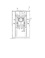
図1は本発明の実施形態の基本となる形態(以下「基本形態」という)に係る写真シール作成装置の側面図であり、図2は図1のX−X線における断面図であり、図3はこの写真シール作成装置の平面図である。以下、これら図1〜図3を参照して、本基本形態に係る写真シール作成装置の全体構成について説明する。
Embodiments of the present invention will be described below with reference to the accompanying drawings.
<1. Basic form>
<1.1 Overall configuration>
FIG. 1 is a side view of a photo sticker creating apparatus according to a basic form of an embodiment of the present invention (hereinafter referred to as “basic form”), and FIG. 2 is a cross-sectional view taken along line XX of FIG. 3 is a plan view of this photographic sticker producing apparatus. Hereinafter, with reference to FIGS. 1 to 3, the overall configuration of the photo sticker creating apparatus according to the present basic embodiment will be described.
この写真シール作成装置は、利用者Uが入る撮影室2と、利用者Uの撮影画像を含む合成画像を生成して写真シールとして出力する本体部4とを備えている。
This photo sticker creating apparatus includes a photographing
撮影室2は、利用者Uを撮影するカメラ等を含む撮影装置10と、可動保持部12および懸装保持部14とによって撮影装置10を移動可能かつ撮影方向可変に保持する保持機構とを備えている。可動保持部12は、撮影装置10を上下移動可能かつ撮影方向可変に保持し、前後移動可能に懸装保持部14に懸装される。懸装保持部14は、撮影装置10を上方に移動させて利用者Uの頭上からも撮影できるように、撮影室2内の利用者Uよりも上方(撮影室2の天井に相当する位置)に配置されている。すなわち、懸装保持部14は、本体部4上方に取り付けられた前方梁部材202と撮影室2の後部上方に取り付けられた後方梁部材204との間に架設されている。また、撮影室2の下部には、床面Fを形成する光透過性の板状部材を含み、面光源として上方に光を放って利用者Uを下方から照らす床面照明装置16が、設けられている。
The photographing
本体部4は、コンピュータを中心に構成され各部の制御や画像処理を行う制御装置や、プリンタ、メインディスプレイ装置等を内蔵し、メインディスプレイ装置の表示画面22は、利用者Uに向き合うように配置されていて、利用者Uを等身大に表示したときに少なくとも利用者Uの顔または上半身が収まるようなサイズとなっている。そして、その表示画面22の両側にはライトペン18L,18Rが備え付けられていて、利用者Uは、これらのライトペン18L,18Rを操作することによって、その表示画面22に表示される撮影画像に付加すべき画像を入力することができる。また、本体部4の前面すなわち利用者Uに向き合う面には、操作パネル20も設けられており、この操作パネル20は、写真シールとして出力すべき合成画像を構成する撮影画像を選択するための選択操作手段や、合成画像生成の際に撮影画像に付加される画像(付加画像)としての背景画像や前景画像を指定する指定手段などを含んでいる。さらに、本体部4は、その前面に照明装置(以下「前面照明装置」という)24およびコイン投入口26を備え、その側面に写真シールの取出口28を備えている。
The main body unit 4 is configured mainly by a computer and incorporates a control device that controls each unit and performs image processing, a printer, a main display device, and the like, and the
<1.2 床面照明装置の構成>
図4(a)は本基本形態における床面照明装置16の平面図であり、図4(b)はこの床面照明装置16の側面図である。これらの図が示すように、本基本形態における床面照明装置16は、4個の扁平な直方体状の照明ユニット16a〜16dを並べて構成される。各照明ユニット16a〜16dは、上面の開放されたキャビネット164に環状の蛍光灯(以下「サークル蛍光灯」という)162が点灯回路(不図示)と共に収容された構成となっており、キャビネット164の上面には、撮影室2の床面Fを形成するカバー166が取り付けられる。このカバー166は拡散透過板であり、例えば乳半色のプラスチック板がカバー166として使用される。なお、本基本形態では、4個の照明ユニット16a〜16dによって床面照明装置16が構成されるが、照明ユニットの個数は4個に限定されるものではない。
<1.2 Configuration of floor lighting device>
FIG. 4A is a plan view of the
本基本形態では、上記のように構成される床面照明装置16は、面光源として床面Fから上方に拡散光を放ち、これにより被写体としての利用者Uを下方から照明する。
In this basic mode, the
なお、図4に示した床面照明装置16は面光源として構成されているが、これは一例であり、これに代えて、例えば直管形蛍光灯を撮影室2内の床面Fの左右の縁に沿って配置した構成としてもよい。この構成によっても床面Fから上方に向かう光によって利用者Uを照らすことができる。
Although the
<1.3 撮影装置の構成>
図5(a)は本基本形態における撮影装置10の正面図であり、図5(b)はこの撮影装置10の透視平面図であり、図5(c)はこの撮影装置10の透視側面図である。これらの図が示すように、本基本形態における撮影装置10は、カメラ106と液晶ディスプレイパネル(以下「LCD」と略記する)108とフラッシュ110とサークル蛍光灯112とが円盤状のケース102に収容されて一体化された構成となっており、ケース102の前面には透明カバー104が取り付けられている。そして、この透明カバー104を通して、サークル蛍光灯112およびフラッシュ110からの光が利用者Uを照らし、カメラ106が利用者Uを撮影し、LCD108に表示される撮影画像を利用者Uが見ることができるように、カメラ106、フラッシュ110、サークル蛍光灯112およびLCD108が、ケース102内に固定的に配置されている。また、ケース102の上部には、カメラ106による撮影画像を画像ファイルとして本体部4内の制御装置に取り込んで一時的に保存するための処理(以下「キャプチャ処理」という)を起動するためのスイッチとして、2つの押しボタン114が設けられている。さらに、ケース102には、その両側方向に張り出した扁平部分として把持部102a,102bが設けられている。これら把持部102a,102bは、撮影装置10の位置や方向を調整してカメラ位置(以下「撮影位置」ともいう)や撮影方向を設定する際に利用者Uによって把持される。
<1.3 Configuration of photographing apparatus>
5A is a front view of the photographing
この撮影装置10において、カメラ106は、撮影室2において床面F上に存在する利用者Uを撮影して撮影画像を表す画像信号を出力する。典型的には、CCD(電荷結合素子)を利用してデジタル画像信号を生成するデジタルカメラがカメラ106として使用される。LCD108は、上記画像信号の表す画像を表示するように構成されており、カメラ106によって得られる撮影画像を確認するために使用される。サークル蛍光灯112は、カメラ106の撮影方向を照らす照明手段であって、本写真シール作成装置の動作中は常時点灯される。フラッシュ110は、押しボタン114が押下されると、数秒程度の予め決められた時間の経過後にカメラ106の撮影方向に閃光を放つ。そして、フラッシュ110から閃光が放たれると、その閃光で照らされた利用者Uのカメラ106による撮影画像を表す画像信号が本体部4内の制御装置に転送され、画像ファイルとして一時的に保存される。
In the photographing
<1.4 撮影装置の保持機構の構成>
図6(a)は本基本形態における撮影装置10の保持機構の側面図であり、図6(b)はこの保持機構の正面図であり、図6(c)はこの保持機構の下面図である。本基本形態における撮影装置10の保持機構は、既述のように、可動保持部12と懸装保持部14とからなる。
<1.4 Structure of holding mechanism of photographing apparatus>
6A is a side view of the holding mechanism of the photographing
可動保持部12は、伸縮管部材121と、撮影装置10を伸縮管部材121の最下部(先端部)に取り付けるための取付部材122と、先端が取付部材122に繋がれた可撓性ワイヤを含むロールバネ123とから構成されている。そして、伸縮管部材121は、下部を上部に嵌め込み可能な複数の管部分からなり内部にスライドレール121bを含んでいる。この伸縮管部材121とロールバネ123とにより、伸縮管部材121によって決まる所定範囲内で、撮影装置10を上下方向に移動させ、任意位置に停止させることができる。また、撮影装置10は、左右方向に延びる水平軸を中心とする回動(以下「水平軸回動」という)が可能で、かつ撮影装置10内のカメラ106の光軸を中心とする回動(以下「光軸回動」という)が可能となるように、取付部材122に取り付けられている。
The
懸装保持部14は、撮影室2内の利用者Uに対して前後方向に水平に延びるレール142と、車輪144を有する台車146とを含み、レール142に車輪144が乗り、台車146がレール142に案内されて前後方向に移動できるように構成されている。この台車146には、上記の可動保持部12における伸縮管部材121の上端部およびロールバネ本体が取り付けられる。これにより、懸装保持部14のレール142によって決まる所定範囲内で、撮影装置10を可動保持部12と共に前後方向に移動させ、任意位置に停止させることができる。
The
上記のように構成された保持機構によれば、撮影室2内の利用者Uが撮影装置10を把持して、図6(a)に示すように前後方向に移動させたり、図7(a)に示すように上下方向に移動させたりすることができる。これにより、所定範囲内で所望位置にカメラ位置(撮影位置)を設定することができる。また、撮影室2内の利用者Uが撮影装置10を把持して、図7(b)に示すようにカメラ106の撮影方向Dpを所望方向に設定したり、図7(c)に示すようにカメラ106の光軸を中心に回動させることもできる。したがって、例えば利用者Uの頭上からの撮影も可能であり、また、縦長と横長のいずれの撮影画像をも得ることができる。
According to the holding mechanism configured as described above, the user U in the photographing
なお、上述した保持機構の構成は一例に過ぎず、撮影室2内の利用者Uに対して上下および前後方向に移動可能でかつ水平軸回動および光軸回動可能に撮影装置10を保持する機構であれば、他の保持機構を採用してもよい。例えば、可動保持部12において、伸縮管部材121に代えて、上下方向に延びるレールに沿って取付部122を移動させる構成を使用してもよい。
Note that the configuration of the holding mechanism described above is merely an example, and the
<1.5 要部の機能的構成>
図8は、本基本形態に係る写真シール作成装置の要部を機能面から見た構成を示すブロック図である。この写真シール作成装置の要部は、機能的には、カメラ52と、確認表示部54と、ビデオ分配部56と、キャプチャ制御部58と、画像処理部60と、メイン表示部62と、写真シール出力部64と、コイン入力部66と、操作部68と、照明部70と、I/O制御部72と、ペン入力部74と、ペン入力制御部76と、メイン制御部80とから構成される。
<1.5 Functional configuration of essential parts>
FIG. 8 is a block diagram showing a configuration of the main part of the photo sticker creating apparatus according to the present basic mode as viewed from the functional aspect. The main parts of this photo sticker creating apparatus are functionally the
この構成において、カメラ52と確認表示部54は、撮影装置10内のカメラ106とLCD108にそれぞれ相当する。ビデオ分配部56は、本体部4内の制御装置に含まれるハードウェアによって実現され、押しボタン114が押下されるまでの間にカメラ52によって取り込まれる撮影方向Dpの画像(「スルー画像」と呼ばれる)の信号を確認表示部54とキャプチャ制御部58とに分配する。これにより、スルー画像は、確認表示部54に表示されると共に、キャプチャ制御部58を通して画像処理部60経由でメイン表示部62にも表示される。キャプチャ制御部58は、制御装置に含まれるハードウェアと制御装置内のコンピュータが実行するソフトウェアとによって実現され、キャプチャ処理を実行する。すなわち、利用者Uの撮影のために押しボタン114が押下されると、メイン制御部80からの指示に基づき、利用者Uの撮影画像を表す信号としてカメラ52から出力される画像信号を直接に(ビデオ分配部56を介さずに)受け取り、画像処理部60内に画像ファイルとして一時的に格納する。画像処理部60は、制御装置に含まれるハードウェアと制御装置内のコンピュータが実行するソフトウェアとによって実現され、メイン制御部80からの指示に基づき、その内部に格納された画像ファイルの表す撮影画像と、操作パネル20によって指定される背景画像や前景画像および/またはライトペン18L,18Rによって手書きで入力された画像(以下「手書き画像」)とを合成することにより、合成画像を生成する。メイン表示部62は、本体部4におけるメインディスプレイ装置に相当し、画像処理部60によって生成される合成画像を表示する。写真シール出力部64は、本体部4に内蔵されるプリンタに相当し、メイン制御部80からの指示に基づき、画像処理部60で生成された合成画像を写真シールとして出力する。
In this configuration, the
また、コイン入力部66は、本体部4におけるコイン投入口26と制御装置内のハードウェアとによって実現され、コイン投入口26に投入されたコインを検出して、投入コインを示すコイン信号を出力する。操作部68は、本体部4における操作パネル20と撮影装置10における押しボタン114とに相当し、操作パネル20または押しボタン114が利用者Uによって操作されると、その操作内容を示す操作信号を出力する。照明部70は、本体部4における床面照明装置16および前面照明装置24と撮影装置10におけるサークル蛍光灯112とに相当し、メイン制御部80からの指示に基づきI/O制御部72によって調光および点灯/消灯が制御される。I/O制御部72は、制御装置内のハードウェアによって実現され、メイン制御部80からの指示に基づき、照明部70を制御すると共に、コイン入力部66からのコイン信号や操作部68からの操作信号をメイン制御部80へ転送する。ペン入力部74は、本体部4におけるライトペン18L,18Rに相当し、利用者Uによって操作されると、その操作内容を示すペン入力信号を出力する。ペン入力制御部76は、制御装置に含まれるハードウェアと制御装置内のコンピュータが実行するソフトウェアとによって実現され、ライトペン18L,18Rからペン入力信号を受け取って、利用者Uの操作内容に基づく画像を表す信号を生成し、これを手書き画像信号としてメイン制御部80に転送する。ここで2人の利用者Uによって2つのライトペン18L,18Rが同時に操作された場合には、ペン入力制御部76は、左のライトペン18Lからのペン入力信号と右のライトペン18Rからのペン入力信号とを交互に受け取り、それぞれのペン入力信号に基づく手書き画像信号を生成する。これにより、2本のライトペン18L,18Rに対する同時操作に応じて並行的に2つの手書き画像が入力されることになる。
The
メイン制御部80は、制御装置内のコンピュータがソフトウェアを実行することによって実現され、上述のようにして入力されるコイン信号や操作信号に基づき各部を制御するために、上述のように各部に指示を出す。また、ペン入力制御部76から手書き画像信号を受け取ると、これを、撮影画像と合成すべき付加画像の信号として画像処理部60に転送する。また、制御装置内のコンピュータは、タイマー機能を備えており、メイン制御部80は、このタイマー機能を利用して、押しボタンスイッチ114が押下されてからキャプチャ処理が開始されるまでの時間や、キャプチャ処理を許容する時間、ライトペン18L,18Rによる手書き画像の入力を許容する時間を管理する。
The
<1.6 動作>
図9は、本基本形態による写真シール作成のための処理手順を示すフローチャートである。
<1.6 Operation>
FIG. 9 is a flowchart showing a processing procedure for creating a photo sticker according to this basic mode.
本基本形態に係る写真シール作成装置は、起動されると投入口26へのコイン投入を待機する状態となる(ステップS10)。この待機状態では、カメラ52および確認表示部54は動作しているが、メイン制御部80は、操作部68からの操作信号およびペン入力制御部76からの手書き画像信号を無視する。その結果、撮影装置10における押しボタン114が押下されても、キャプチャ制御部58によるキャプチャ処理は実行されず、また、操作パネル20やライトペン18R,18Lが操作されても、画像処理部60や写真シール出力部64は動作しない。この待機状態において、コインが投入されると、そのコインを示すコイン信号がI/O制御部72を介してメイン制御部80に入力され、メイン制御部80は、このコイン信号に基づき投入されたコインの金額を算出する。続けて複数のコインが投入されると、メイン制御部80は、それらのコインの金額を合計する。そして、1個のコインの金額または続けて投入された複数個のコインの合計額が所定の金額に到達すると、撮影処理を開始する(ステップS12)。
When activated, the photo sticker creating apparatus according to the present basic mode waits for the insertion of coins into the insertion slot 26 (step S10). In this standby state, the
撮影処理が開始されると、メイン制御部80は、まず、予め決められた時間(以下「撮影時間」という)が経過するとタイムアウトとなるようにタイマーを設定し、そのタイマーをスタートさせる。その後、タイムアウトとなるまで、操作部68としての押しボタン114が押下されたか否かを操作信号によって調べる。この間に押しボタン114が押下されると、メイン制御部80は、撮影開始を利用者にメイン表示部64の画面で知らせ、数秒程度の予め決められた時間の経過後にカメラ52に撮影信号(シャッター信号)を送る。これにより、カメラ52のシャッター動作と同期してフラッシュ110が閃光を放ち、キャプチャ制御部58がキャプチャ処理を開始する。すなわち、キャプチャ制御部58は、フラッシュ110からの閃光で照らされた利用者Uの撮影画像を表す信号としてカメラ52から出力される画像信号を直接に受け取り、画像処理部60内に画像ファイルとして格納する。このようにして所定の撮影時間の間、押しボタン114が押下される毎にキャプチャ処理が実行され、撮影画像が画像ファイルとして一時的に保存される。撮影時間が経過すると、タイムアウトとなって撮影処理を終了する。また、撮影時間の経過前であっても、操作パネル20に対して撮影処理の終了を指示する操作が行われると、撮影処理を終了する。
When the photographing process is started, first, the
撮影処理を終了すると、メイン制御部80は写真選択処理を開始する(ステップS14)。写真選択処理では、メイン制御部80の指示に基づき、その前の撮影処理におけるキャプチャ処理で画像処理部60に保存された画像ファイルの表す撮影画像(通常は複数個)がメイン表示部62に表示される。そして、これを見た利用者Uによる操作に基づき、画像ファイルの表す撮影画像のうちのいずれかが選択される。このようにして撮影画像が選択されると、メイン制御部80は、ライトペン18L,18Rによる操作に基づく手書き画像の入力のための処理(以下「らくがき処理」という)を開始する(ステップS16)。
When the shooting process is finished, the
らくがき処理が開始されると、メイン制御部80は、まず、予め決められた時間(以下「らくがき時間」という)が経過するとタイムアウトとなるようにタイマーを設定し、そのタイマーをスタートさせる。メイン制御部80は、らくがき処理が開始されるまではペン入力制御部76からの手書き画像信号を無視しているが、らくがき処理が開始されるとタイムアウトとなるまで、ペン入力制御部76から出力される手書き画像信号を受け取り、これを画像処理部60に転送する。画像処理部60は、この手書き画像信号の表す画像を写真選択処理で選択された撮影画像(以下「選択撮影画像」という)と合成する。これによって得られた合成画像は、メイン表示部62に表示される。このようにして所定のらくがき時間の間、左右のライトペン18R,18Lのいずれかが操作される毎に、その操作に基づく手書き画像が選択撮影画像に順次合成されていき、合成画像がメイン表示部62に表示される。ところで、表示部62に相当するメインディスプレイ装置の表示画面22は、利用者Uに向き合うように配置されていて、利用者Uを等身大に表示したときに少なくとも利用者Uの顔または上半身が収まるようなサイズとなっている。このため、利用者Uは、表示画面22に等身大で自分を表示させ、左右のライトペン18R,18Lの一方または双方で画面22に化粧に相当する画像を描くことで、鏡を見ながら化粧するかのような体験を楽しむことができる。このようならくがき時間が経過してタイムアウトになると、メイン制御部80は、ペン入力制御部76から出力される手書き画像信号を無視する。これにより、らくがき時間の経過後は、手書き画像は選択撮影画像に合成されない。
When the scribing process is started, the
らくがき時間の経過後又はらくがき時間の経過前に、操作パネル20に対する操作によりプリントが指示されると、メイン制御部80は、プリント処理を開始する(ステップS18)。すなわち、メイン制御部80は、プリント指示を示す操作信号を受け取ると、これに基づき、その時点でメイン表示部62に表示されている合成画像の出力を画像処理部60を介して写真シール出力部64に指示する。これにより、写真シール出力部64としてプリンタは、その合成画像を写真シールとして出力する。これにより、プリント処理が終了する。出力された写真シールは、本体部4の側面に設けられた取出口28から利用者Uによって取り出される。
When printing is instructed by an operation on the
上記プリント処理が終了すると、ステップS10へ戻り、所定の金額に相当するコインが新たにコイン投入口26に投入されるまで待機状態となる。この待機状態において、所定の金額に相当するコインが新たに投入されると、上記と同様の処理(ステップS12〜S18)が実行され、その後、再びステップS10へ戻る。
When the printing process is completed, the process returns to step S10, and a standby state is entered until a coin corresponding to a predetermined amount is newly inserted into the
<1.7 効果>
本基本形態では、カメラ106とLCD108とサークル蛍光灯112とフラッシュ110とが図5に示すように撮影装置10として一体化されている。そして、この撮影装置10は、可動保持部12と懸装保持部14とからなる保持機構により、撮影室2内の利用者Uに対して前後および上下方向に移動可能でかつ水平軸回動および光軸回動可能に保持される。このため、利用者Uは、撮影装置10の位置や向きを手で変えることにより、所定範囲内で任意に撮影位置(カメラ位置)および撮影方向等を設定することができる。しかも、撮影位置や撮影方向等を任意に設定しても、サークル蛍光灯112により撮影方向が照らされ、撮影装置10内のLCD108で撮影画像を確認できるので、利用者Uを容易かつ良好に撮影することができる。
<1.7 Effect>
In this basic form, the
また、撮影室2に床面照明装置16が設けられ、床面Fから上方に向けて利用者Uが照らされるので、従来に見られない照明効果が得られる。この照明効果は、撮影位置や撮影方向の設定の自由度の高さと相俟って、斬新な演出の施された撮影を可能とする。
In addition, since the
さらに、懸装保持部14は撮影室2内の利用者Uの上方に配置され、その懸装保持部14に上端部が取り付けられた可動保持部12は、上下方向に伸縮自在の構成となっている。このため、撮影室2の限られた空間を有効に利用しつつ、撮影位置や撮影方向につき高い自由度を得ることができる。また、この自由度の高さは、床面照明装置16による照明効果と相俟って斬新な撮影を可能とする。例えば、床面照明装置16によって逆光効果を与えつつ利用者Uの頭上から撮影することが可能となる。さらに、可動保持部12が上下方向に伸縮自在に構成されていることから、撮影後に撮影装置10を上方に置くことにより、ライトペン18L,18Rや操作パネル20に対する操作のための空間を広く確保することができる。
Furthermore, the
<1.8 変形例>
上記基本形態では、可動保持部12は前後移動可能に懸装保持部14の懸装されているが、これに代えて、可動保持部12(伸縮管部材121の最上部およびロールバネ123)を懸装保持部14または撮影室2の天井部分に固定的に取り付けてもよい。この場合、撮影装置10の位置を前後方向に変更することはできないが、上下方向には移動可能でかつ撮影方向等も任意に設定できるので、撮影位置や撮影方向等につきなお高い自由度が得られ、利用者Uの頭上から撮影することも可能である。
<1.8 Modification>
In the above basic form, the movable holding
<2.実施形態>
上記基本形態に係る写真シール作成装置を或る客が利用したいときにその写真シール作成装置が使用中であれば、その客は現時点の利用者による写真シール作成が終了するまで待つことになる。すなわち、写真シール作成装置の利用のための順番待ちが生じる。本発明の一実施形態に係る写真シール作成装置は、このような順番待ちの発生を抑制する機能を有している。この順番待ち発生の抑制は、撮影処理(図9のステップS10参照)が開始されてからプリント処理(図9のステップS18参照)が終了するまでの時間(以下「遊技時間」という)を短縮して客(写真シール撮影装置の利用者)の回転率を向上させるという機能(以下「客回転率アップ機能」という)により実現される。以下、このような本発明の実施形態について説明する。
<2. Embodiment>
If a certain customer wants to use the photo sticker creating apparatus according to the above basic form and the photo sticker creating apparatus is in use, the customer waits until the photo sticker creation by the current user is completed. That is, there is a waiting order for using the photo sticker creating apparatus. The photo sticker creating apparatus according to an embodiment of the present invention has a function of suppressing the occurrence of such a waiting order. This suppression of the occurrence of waiting for a turn reduces the time (hereinafter referred to as “game time”) from the start of the shooting process (see step S10 in FIG. 9) to the end of the print process (see step S18 in FIG. 9). This is realized by the function of improving the rotation rate of the customer (user of the photo sticker photographing apparatus) (hereinafter referred to as “customer rotation rate increasing function”). Hereinafter, embodiments of the present invention will be described.
本実施形態の構成は、基本的には上記基本形態と同様である(図1〜図8参照)。しかし本実施形態では、メイン制御部80(図8参照)を実現するソフトウェアの内容が上記基本形態の場合と相違し、メイン制御部80による制御動作に基づき図10に示す手順に従って写真シールが作成される。そこで以下では、図10を参照して本実施形態による写真シール作成のための処理手順を説明する。なお、本実施形態の各構成要素については、上記基本形態において対応する構成要素と同一の参照符号を付して詳しい説明を省略する。 The configuration of the present embodiment is basically the same as that of the basic mode (see FIGS. 1 to 8). However, in this embodiment, the content of the software that implements the main control unit 80 (see FIG. 8) is different from that in the basic mode, and a photo sticker is created according to the procedure shown in FIG. Is done. Therefore, hereinafter, a processing procedure for creating a photo sticker according to the present embodiment will be described with reference to FIG. In addition, about each component of this embodiment, the same referential mark as the corresponding component in the said basic form is attached | subjected, and detailed description is abbreviate | omitted.
本実施形態では、写真シール作成装置が起動されると、まず、メイン制御部80が客待ちランクRwを“0”に初期化し(ステップS20)、客待ち判定タイムTwをその初期値であるTw0に設定する(ステップS22)。その後、客待ちカウンタ値Cwを“0”に初期化する(ステップS24)。ここで、客待ちランクRw、客待ち判定タイムTw、および客待ちカウンタ値Cwは、上記の回転率アップ機能を実現するために導入された変数である。より詳しくは、客待ち判定タイムTwは、写真シール作成装置のアイドル時間に基づいて上記順番待ち(「客待ち」ともいう)の発生状況を判定するために導入されたものであり、また、客待ちカウンタ値Cwは、写真シール作成装置のアイドル時間を計測するために導入されたものである。そして、客待ち判定タイムの初期値Tw0は、客待ちが発生している場合のアイドル時間の上限に相当するカウンタ値Cwとして予め設定されている。なお、「アイドル時間」とは、写真シール作成装置の使用(プリント処理)が終了してから新たな利用者によって写真シール作成装置の使用(撮影処理)が開始されるまでの時間、すなわち写真シール作成動作が抑止されてから次に写真シール作成動作が許容されるまでの時間を意味するものとする。
In the present embodiment, when the photo sticker creating apparatus is activated, first, the
客待ちカウンタ値Cwが初期化されると、メイン制御部80は、客待ちカウンタ値Cwが客待ち判定タイムTwに等しいか否かを判定する(ステップS26)。最初はCw=0であるのでCw≠Twと判定され、ステップS32へ進んで客待ちカウンタ値Cwを“1”だけ増やす。その後、メイン制御部80は、コイン入力部66からのコイン信号に基づき、所定金額に相当するコインがコイン投入口26に投入されたか否かを判定し(ステップS34)、所定金額に相当するコインが投入されていなければステップS26へ戻る。以降、所定金額のコインが投入されない限り、ステップS26→S32→S34を繰り返し実行する。この間に、客待ちカウンタ値Cwが客待ち判定タイムTwに等しくなると、客待ちランクRwが“0”でない限り、客待ちランクRwを“1”だけ減じ、客待ち判定タイムTwを更新する(ステップS26〜S31)。この客待ち判定タイムTwの更新では、客待ち判定タイムTwにΔTだけ加えた値を新たな客待ち判定タイムTwとする(ステップS31)。ここでΔTは、予め決められた正値であって客待ちランクRwの減少速度を決定する。客待ち判定タイムTwの更新後は、上記と同様、客待ちカウンタ値Cwを“1”だけ増やした後、所定金額に相当するコインがコイン投入口26に投入されたか否かを判定し(ステップS32,S34)、所定金額に相当するコインが投入されていなければステップS26へ戻る。
When the customer waiting counter value Cw is initialized, the
上記のようにしてステップS26〜S34が実行されることにより、所定金額のコインが投入されるまでの時間が長くなるほど、すなわちアイドル時間が長くなるほど、客待ちランクRwが小さくなる。ただし、客待ちランクRwは“0”よりも小さくなることはない。このようにしてステップS26〜S34が実行されている間に所定金額のコインが投入されると、ステップS36へ進む。 By executing steps S26 to S34 as described above, the customer waiting rank Rw decreases as the time until a predetermined amount of coins is inserted, that is, as the idle time increases. However, the customer waiting rank Rw does not become smaller than “0”. If a predetermined amount of coins is inserted while steps S26 to S34 are executed in this way, the process proceeds to step S36.
ステップS36においてメイン制御部80は、客待ちカウンタ値Cwの値が客待ち判定タイムの初期値Tw0よりも大きいか否かを判定する。その結果、Cw≦Tw0であれば、客待ちが生じていると見なして客待ちランクRwを“1”だけ増やした(ステップS38)後に、ステップS40へ進み、Cw>Tw0であれば、客待ちが生じていないと見なして客待ちランクRwを変えることなく、ステップS40へ進む。
In step S36, the
ステップS40においてメイン制御部80は、客待ちランクRwに応じて撮影時間T1とらくがき時間T2を設定する(ステップS40)。このとき、客待ちランクRwが大きければ撮影時間T1とらくがき時間T2が短くなるように設定する。
In step S40, the
このようにして撮影時間T1とらくがき時間T2が設定された後は、上記基本形態と同様にして(図9のステップS12〜S18)、撮影処理(ステップS42)、写真選択処理(ステップS44)、らくがき処理(ステップS46)、およびプリント処理(ステップS46)が順に実行される。このとき、撮影処理の許容される時間(撮影時間T1)とらくがき処理の許容される時間(らくがき時間T2)は、客待ちランクRwが大きいほど短くなる。 After the shooting time T1 and the scribing time T2 are set in this manner, the shooting process (step S42), the photo selection process (step S44), the same as the basic mode (steps S12 to S18 in FIG. 9), The scribing process (step S46) and the printing process (step S46) are sequentially executed. At this time, the time allowed for the shooting process (shooting time T1) and the time allowed for the graffiti process (graffiti time T2) become shorter as the customer waiting rank Rw increases.
プリント処理が終了すると、所定金額のコイン投入に対応する写真シール作成動作が終了し、ステップS22へ戻る。以降、ステップS22〜S48が繰り返し実行される。 When the printing process ends, the photo sticker creation operation corresponding to the insertion of a predetermined amount of coins ends, and the process returns to step S22. Thereafter, steps S22 to S48 are repeatedly executed.
以上のような本実施形態によれば、写真シール作成動作(ステップS42〜S48)が終了してから所定金額のコインが新たに投入されるまでの時間(アイドル時間)を表す客待ちカウンタ値Cwが客待ち判定タイムの初期値Tw0に達しない場合には、ステップS30は実行されずステップS38が実行されるので、写真シール作成動作が開始される毎に客待ちランクRwが“1”ずつ増える。そして、この客待ちランクRwが大きくなるほど撮影時間T1とらくがき時間T2が短くなる。これは、アイドル時間が短くなるほど、すなわち客待ちの程度または可能性が大きくなるほど、撮影時間T1とらくがき時間T2が短くなることを意味する。したがって、客待ちの程度または可能性が大きくなると、写真シール作成に許容される時間が短くなって客回転率が向上し、客待ちが抑制される。一方、アイドル時間を表す客待ちカウンタ値Cwが客待ち判定タイムTwを越えると、ステップS30が実行されステップS38は実行されないので、客待ちランクRwはアイドル時間の長さに応じて減少する(ステップS26〜S31参照)。これは、アイドル時間が長くなるほど、撮影時間T1とらくがき時間T2が長くなることを意味する。したがって、客待ちが生じなくなると(またはその可能性が少なくなると)、写真シール作成に許容される時間が長くなる。 According to the present embodiment as described above, the customer waiting counter value Cw representing the time (idle time) from when the photo sticker creation operation (steps S42 to S48) is completed until a predetermined amount of coins is newly inserted. If the initial value Tw0 of the customer waiting determination time has not been reached, step S30 is not executed and step S38 is executed, so that the customer waiting rank Rw increases by "1" each time the photo sticker creation operation is started. . As the customer waiting rank Rw increases, the shooting time T1 and the writing time T2 become shorter. This means that the shooting time T1 and the writing time T2 become shorter as the idle time becomes shorter, that is, as the degree or possibility of waiting for customers increases. Therefore, when the degree or possibility of waiting for customers increases, the time allowed for photo sticker creation is shortened, the customer turnover rate is improved, and waiting for customers is suppressed. On the other hand, when the customer waiting counter value Cw representing the idle time exceeds the customer waiting determination time Tw, step S30 is executed and step S38 is not executed. Therefore, the customer waiting rank Rw decreases according to the length of the idle time (step). S26 to S31). This means that the longer the idle time, the longer the shooting time T1 and the writing time T2. Accordingly, when waiting for customers does not occur (or when the possibility thereof decreases), the time allowed for photo sticker creation becomes longer.
このように本実施形態では、写真シール作成に許容される時間(遊技時間)がアイドル時間と正の相関関係を有するように、撮影時間T1およびらくがき時間T2が客待ちランクRwに基づき調整される(ステップS40)。その結果、写真シール作成装置利用のための順番待ちが生じる場合には、順番待ちしている客の待ち時間を短縮することができ、順番待ちの生じる可能性が無いか少ないときには、長い時間、客に写真シール作成を楽しませることができる。すなわち本実施形態によれば、順番待ちの発生が自動的に抑制されるので順番待ちによる客の不満を緩和できると共に、順番待ちが生じない状況のときには遊技時間が長くなるので客の満足度を高めることができる。 As described above, in the present embodiment, the shooting time T1 and the graffiti time T2 are adjusted based on the customer waiting rank Rw so that the time allowed for the photo sticker creation (game time) has a positive correlation with the idle time. (Step S40). As a result, when waiting for the turn for using the photo sticker creation device occurs, the waiting time of customers waiting for the turn can be shortened, and when there is little or no possibility of waiting for the turn, a long time, Customers can enjoy creating photo stickers. In other words, according to the present embodiment, the occurrence of waiting for waiting is automatically suppressed, so that customer dissatisfaction due to waiting for waiting can be alleviated. Can be increased.
<3.客回転率アップ機能を備えたゲーム装置>
上記実施形態のように客回転率アップ機能によって順番待ちの発生を自動的に抑制するという手法は、コイン投入に応答してプレーヤにゲームを許容するゲーム装置に一般的に適用可能である。以下、このような客回転率アップ機能を有するゲーム装置について説明する。
<3. Game device with customer turnover function>
The method of automatically suppressing the occurrence of turn waiting by the customer turnover function as in the above embodiment is generally applicable to game devices that allow a player to play a game in response to coin insertion. Hereinafter, a game apparatus having such a customer turnover function will be described.
図11は、このゲーム装置の構成を示す機能ブロック図である。このゲーム装置は、それが提供するゲーム(以下「対象ゲーム」という)の内容に応じたハードウェアおよびソフトウェアとそのソフトウェアを実行するコンピュータとから構成され、機能面から見ると、ゲーム装置本体200と、コイン入力部202と、操作部204と、I/O制御部206と、メイン制御部208とを備えている。ゲーム装置本体200は、対象ゲームの内容に応じたハードウェアおよびソフトウェアによって実現される。コイン入力部202は、対象ゲームを開始するために投入されるコインの投入口と投入されたコインを検出するハードウェアとで実現され、投入コインを示すコイン信号を出力する。操作部204は、対象ゲームの内容に応じてプレーヤによって操作されるハードウェアとして実現され、その操作内容を示す操作信号を出力する。I/O制御部206は、ハードウェアおよびソフトウェアによって実現され、コイン入力部202からのコイン信号や操作部204からの操作信号をメイン制御部208へ転送する。メイン制御部208は、コンピュータによって実行されるソフトウェアによって実現され、コイン信号および操作信号に応じてゲーム装置本体200を制御する。
FIG. 11 is a functional block diagram showing the configuration of this game apparatus. This game apparatus is composed of hardware and software corresponding to the contents of a game provided by the game apparatus (hereinafter referred to as “target game”) and a computer that executes the software. , A
図12は、上記のように構成されたゲーム装置によってゲームを提供するための処理手順を示すフローチャートである。このフローチャートでは、図10に示したフローチャートにおけるステップS40に代えてステップS200が、ステップS42〜S48に代えてステップS202が、それぞれ使用されている。その他のステップについては、図10に示したフローチャートにおけるステップと同様であるので、対応するステップには同一のステップ番号を付すものとする。 FIG. 12 is a flowchart showing a processing procedure for providing a game by the game device configured as described above. In this flowchart, step S200 is used instead of step S40 in the flowchart shown in FIG. 10, and step S202 is used instead of steps S42 to S48. The other steps are the same as those in the flowchart shown in FIG. 10, and therefore the corresponding steps are denoted by the same step numbers.
このゲーム装置においても、メイン制御部208により、上記実施形態と同様にして、ゲームが終了してから次にゲームが許容されるまで(所定金額のコインが新たに投入されるまで)の時間であるアイドル時間が客待ちカウンタ値Cwによって表され、これに基づき客待ちの状況を示す客待ちランクRwが設定される(ステップS20〜S38)。
In this game device as well, in the same manner as in the above embodiment, the
本実施形態ではメイン制御部208は、上記のようにして設定された客待ちRwに応じて、対象ゲームを許容する時間である遊技時間を設定する(ステップS200)。このとき、客待ちランクRwが大きければ遊技時間が短くなるように設定する。この後、メイン制御部208は、ゲーム制御処理を開始する(ステップS202)。すなわち、操作部204からの操作信号に応じてゲーム装置本体200を制御する。これにより、上記遊技時間の間、対象ゲームが許容される。すなわち、上記遊技時間だけ、このゲーム装置においてプレーヤが対象ゲームを楽しめる状態となる。遊技時間の経過後はステップS20へ戻り、以降、ステップS24〜S38、S200、S202が繰り返し実行される。
In the present embodiment, the
このゲーム装置によれば、上記実施形態と同様、遊技時間がアイドル時間と正の相関関係を有するように遊技時間が調整される。このため、ゲーム装置利用のための順番待ちの程度または可能性が大きくなると、遊技時間が短くなって客回転率が向上し、順番待ちが生じなくなると(または可能性が少なくなると)、遊技時間が長くなる。したがって、順番待ちの発生が自動的に抑制されるので順番待ちによる客の不満を緩和できると共に、順番待ちが生じない状況のときには遊技時間が長くなるので客の満足度を高めることができる。 According to this game device, the game time is adjusted so that the game time has a positive correlation with the idle time, as in the above embodiment. For this reason, if the degree or possibility of waiting for a game device is increased, the game time is shortened and the customer turnover rate is improved, and if the turn is no longer waited (or the possibility is reduced), the game time is increased. Becomes longer. Therefore, since the occurrence of waiting for waiting is automatically suppressed, customer dissatisfaction due to waiting for waiting can be alleviated, and the game time is lengthened in a situation where waiting for waiting does not occur, so that customer satisfaction can be improved.
なお、このゲーム装置における遊技時間の設定(調整)は、ゲーム制御におけるシーケンスやスピードを客待ちランクRwに応じて変えることにより行うことができる。また、ゲーム制御で使用される秒タイマーにおける「1秒」を例えば「0.9秒」や「0.8秒」に置き換えることによっても、遊技時間を調整することができる。さらに、ゲーム制御において遊技時間を決定するタイマーの設定自体を客待ちランクRwに応じて変更するようにしてもよい。 Note that the setting (adjustment) of the game time in this game apparatus can be performed by changing the sequence and speed in the game control in accordance with the customer waiting rank Rw. The game time can also be adjusted by replacing “1 second” in the second timer used in the game control with, for example, “0.9 seconds” or “0.8 seconds”. Furthermore, the timer setting itself for determining the game time in the game control may be changed according to the customer waiting rank Rw.
2 …撮影室
4 …本体部
10 …撮影装置
12 …可動保持部
14 …懸装保持部
16 …床面照明装置
18L,18R …ライトペン
20 …操作パネル
22 …メインディスプレイ装置の表示画面
26 …コイン投入口
28 …写真シール取出口
52 …カメラ
54 …確認表示部(LCD)
58 …キャプチャ制御部
60 …画像処理部
62 …メイン表示部(メインディスプレイ装置)
64 …写真シール出力部(プリンタ)
66 …コイン入力部
68 …操作部(操作パネル、押しボタン)
70 …照明部
74 …ペン入力部
80 …メイン制御部
102a,102b …把持部
106 …カメラ
108 …LCD
110 …フラッシュ
112 …サークル蛍光灯
114 …押しボタン
200 …ゲーム装置本体
202 …コイン入力部
204 …操作部
208 …メイン制御部
Dp …撮影方向
U …利用者
DESCRIPTION OF
58 ...
64 ... Photo sticker output unit (printer)
66 ...
DESCRIPTION OF
DESCRIPTION OF
Claims (7)
利用者を撮影する撮影手段と、Photographing means for photographing a user;
前記撮影手段により撮影された撮影画像の編集を行う編集手段と、Editing means for editing a photographed image photographed by the photographing means;
所定額の入金を検知した場合、前記ゲームを提供するための複数の処理を所定の順序で実行すると共に、前記複数の処理のうち前記利用者の操作入力を必要とする一部の処理のそれぞれにつき当該処理の実行が許容される許容時間の長さを前記写真撮影遊戯装置の稼働状況に基づいて設定する制御手段と、When a predetermined amount of payment is detected, a plurality of processes for providing the game are executed in a predetermined order, and each of a part of the plurality of processes that require an operation input by the user Control means for setting the length of the permissible time during which the processing is allowed based on the operating status of the photography game device,
を備えることを特徴とする、写真撮影遊戯装置。A photography game device characterized by comprising:
前記制御手段は、前記撮影処理を実行する時間の長さおよびらくがき処理を実行する時間の長さを前記許容時間として設定することを特徴とする、請求項1に記載の写真撮影遊戯装置。2. The photographic game device according to claim 1, wherein the control unit sets the length of time for executing the shooting process and the length of time for executing a graffiti process as the allowable time.
前記ゲーム装置の稼働状態に基づいて前記遊戯時間の長さを設定する制御手段を備え、Control means for setting the length of the game time based on the operating state of the game device;
前記制御手段は、前記ゲームの実行を制御するためのタイマーを含み、当該タイマーにおける単位時間の長さを変更することにより前記遊戯時間の長さを設定することを特徴とする、ゲーム装置。The game device characterized in that the control means includes a timer for controlling the execution of the game, and sets the length of the game time by changing the length of the unit time in the timer.
Priority Applications (1)
| Application Number | Priority Date | Filing Date | Title |
|---|---|---|---|
| JP2009278833A JP5051209B2 (en) | 2009-12-08 | 2009-12-08 | Photo shooting game device and other game devices |
Applications Claiming Priority (1)
| Application Number | Priority Date | Filing Date | Title |
|---|---|---|---|
| JP2009278833A JP5051209B2 (en) | 2009-12-08 | 2009-12-08 | Photo shooting game device and other game devices |
Related Parent Applications (1)
| Application Number | Title | Priority Date | Filing Date |
|---|---|---|---|
| JP2001132770A Division JP2002328422A (en) | 2001-04-27 | 2001-04-27 | Picture seal preparing device |
Publications (2)
| Publication Number | Publication Date |
|---|---|
| JP2010061161A JP2010061161A (en) | 2010-03-18 |
| JP5051209B2 true JP5051209B2 (en) | 2012-10-17 |
Family
ID=42187931
Family Applications (1)
| Application Number | Title | Priority Date | Filing Date |
|---|---|---|---|
| JP2009278833A Expired - Lifetime JP5051209B2 (en) | 2009-12-08 | 2009-12-08 | Photo shooting game device and other game devices |
Country Status (1)
| Country | Link |
|---|---|
| JP (1) | JP5051209B2 (en) |
Families Citing this family (3)
| Publication number | Priority date | Publication date | Assignee | Title |
|---|---|---|---|---|
| JP5392334B2 (en) * | 2011-10-07 | 2014-01-22 | 日産自動車株式会社 | Charger |
| JP2014211543A (en) * | 2013-04-19 | 2014-11-13 | 株式会社メイクソフトウェア | Photography game machine and control program therefor |
| JP7295374B2 (en) * | 2018-12-14 | 2023-06-21 | フリュー株式会社 | Information processing equipment |
-
2009
- 2009-12-08 JP JP2009278833A patent/JP5051209B2/en not_active Expired - Lifetime
Also Published As
| Publication number | Publication date |
|---|---|
| JP2010061161A (en) | 2010-03-18 |
Similar Documents
| Publication | Publication Date | Title |
|---|---|---|
| JP5814566B2 (en) | IMAGING DEVICE, IMAGING METHOD, AND IMAGING DEVICE CONTROL PROGRAM | |
| JP6395016B2 (en) | Photo sticker creation device | |
| JP5051209B2 (en) | Photo shooting game device and other game devices | |
| JP2020204914A (en) | Electronic apparatus and method for controlling the same | |
| JP2002328422A (en) | Picture seal preparing device | |
| JPWO2015025485A1 (en) | Imaging device and strobe device | |
| JP6256559B2 (en) | PHOTOGRAPHY GAME DEVICE, PHOTOGRAPHY GAME DEVICE CONTROL METHOD, AND PHOTOGRAPHY GAME DEVICE CONTROL PROGRAM | |
| JP2009296457A (en) | Image providing apparatus | |
| JP5380770B2 (en) | Automatic photo creation device and automatic photo creation method | |
| JP4328182B2 (en) | Automatic photo creation device and automatic photo creation method | |
| JP6035488B2 (en) | PHOTOGRAPHY GAME DEVICE, PHOTOGRAPHY GAME DEVICE CONTROL METHOD, AND PHOTOGRAPHY GAME DEVICE CONTROL PROGRAM | |
| JP2017108410A (en) | Photography game device, control method, and program | |
| JP2008099080A (en) | Automatic photographing apparatus and automatic photographing method | |
| JP5223348B2 (en) | Image shooting device | |
| JP4336215B2 (en) | Automatic photo creation device and automatic photo creation method | |
| JP2008276438A (en) | Automatic photograph creation device and automatic photograph creation method | |
| JP4133245B2 (en) | Automatic photo creation device | |
| JP7364866B2 (en) | Image processing device, editing device | |
| JP2002094906A (en) | Photographing device | |
| JP2004274422A (en) | Image printing apparatus | |
| JP2005345706A (en) | Automatic photographic apparatus and automatic photographing method | |
| JP2013038517A (en) | Device, method and program for photo-taking play | |
| JP6085823B2 (en) | Photography game machine and its control program | |
| JP2004219808A (en) | Automatic photograph forming device | |
| JP2019035805A (en) | Photographic seal machine, photographic seal creation method and photographic seal creation processing program |
Legal Events
| Date | Code | Title | Description |
|---|---|---|---|
| A621 | Written request for application examination |
Free format text: JAPANESE INTERMEDIATE CODE: A621 Effective date: 20091208 |
|
| A131 | Notification of reasons for refusal |
Free format text: JAPANESE INTERMEDIATE CODE: A131 Effective date: 20111115 |
|
| A521 | Written amendment |
Free format text: JAPANESE INTERMEDIATE CODE: A523 Effective date: 20120116 |
|
| TRDD | Decision of grant or rejection written | ||
| A01 | Written decision to grant a patent or to grant a registration (utility model) |
Free format text: JAPANESE INTERMEDIATE CODE: A01 Effective date: 20120626 |
|
| A01 | Written decision to grant a patent or to grant a registration (utility model) |
Free format text: JAPANESE INTERMEDIATE CODE: A01 |
|
| A61 | First payment of annual fees (during grant procedure) |
Free format text: JAPANESE INTERMEDIATE CODE: A61 Effective date: 20120709 |
|
| R150 | Certificate of patent or registration of utility model |
Ref document number: 5051209 Country of ref document: JP Free format text: JAPANESE INTERMEDIATE CODE: R150 Free format text: JAPANESE INTERMEDIATE CODE: R150 |
|
| FPAY | Renewal fee payment (event date is renewal date of database) |
Free format text: PAYMENT UNTIL: 20150803 Year of fee payment: 3 |
|
| FPAY | Renewal fee payment (event date is renewal date of database) |
Free format text: PAYMENT UNTIL: 20150803 Year of fee payment: 3 |
|
| R250 | Receipt of annual fees |
Free format text: JAPANESE INTERMEDIATE CODE: R250 |
|
| R250 | Receipt of annual fees |
Free format text: JAPANESE INTERMEDIATE CODE: R250 |
|
| R250 | Receipt of annual fees |
Free format text: JAPANESE INTERMEDIATE CODE: R250 |
|
| R250 | Receipt of annual fees |
Free format text: JAPANESE INTERMEDIATE CODE: R250 |
|
| R250 | Receipt of annual fees |
Free format text: JAPANESE INTERMEDIATE CODE: R250 |
|
| R250 | Receipt of annual fees |
Free format text: JAPANESE INTERMEDIATE CODE: R250 |
|
| EXPY | Cancellation because of completion of term |