JP5048870B2 - Fuel cell system and operation method thereof - Google Patents
Fuel cell system and operation method thereof Download PDFInfo
- Publication number
- JP5048870B2 JP5048870B2 JP2011526167A JP2011526167A JP5048870B2 JP 5048870 B2 JP5048870 B2 JP 5048870B2 JP 2011526167 A JP2011526167 A JP 2011526167A JP 2011526167 A JP2011526167 A JP 2011526167A JP 5048870 B2 JP5048870 B2 JP 5048870B2
- Authority
- JP
- Japan
- Prior art keywords
- fuel cell
- water
- exhaust gas
- flow path
- water tank
- Prior art date
- Legal status (The legal status is an assumption and is not a legal conclusion. Google has not performed a legal analysis and makes no representation as to the accuracy of the status listed.)
- Expired - Fee Related
Links
Images


Classifications
-
- H—ELECTRICITY
- H01—ELECTRIC ELEMENTS
- H01M—PROCESSES OR MEANS, e.g. BATTERIES, FOR THE DIRECT CONVERSION OF CHEMICAL ENERGY INTO ELECTRICAL ENERGY
- H01M8/00—Fuel cells; Manufacture thereof
- H01M8/04—Auxiliary arrangements, e.g. for control of pressure or for circulation of fluids
- H01M8/04082—Arrangements for control of reactant parameters, e.g. pressure or concentration
- H01M8/04089—Arrangements for control of reactant parameters, e.g. pressure or concentration of gaseous reactants
- H01M8/04119—Arrangements for control of reactant parameters, e.g. pressure or concentration of gaseous reactants with simultaneous supply or evacuation of electrolyte; Humidifying or dehumidifying
- H01M8/04156—Arrangements for control of reactant parameters, e.g. pressure or concentration of gaseous reactants with simultaneous supply or evacuation of electrolyte; Humidifying or dehumidifying with product water removal
-
- H—ELECTRICITY
- H01—ELECTRIC ELEMENTS
- H01M—PROCESSES OR MEANS, e.g. BATTERIES, FOR THE DIRECT CONVERSION OF CHEMICAL ENERGY INTO ELECTRICAL ENERGY
- H01M8/00—Fuel cells; Manufacture thereof
- H01M8/04—Auxiliary arrangements, e.g. for control of pressure or for circulation of fluids
- H01M8/04298—Processes for controlling fuel cells or fuel cell systems
- H01M8/04694—Processes for controlling fuel cells or fuel cell systems characterised by variables to be controlled
- H01M8/04955—Shut-off or shut-down of fuel cells
-
- H—ELECTRICITY
- H01—ELECTRIC ELEMENTS
- H01M—PROCESSES OR MEANS, e.g. BATTERIES, FOR THE DIRECT CONVERSION OF CHEMICAL ENERGY INTO ELECTRICAL ENERGY
- H01M8/00—Fuel cells; Manufacture thereof
- H01M8/10—Fuel cells with solid electrolytes
- H01M2008/1095—Fuel cells with polymeric electrolytes
-
- H—ELECTRICITY
- H01—ELECTRIC ELEMENTS
- H01M—PROCESSES OR MEANS, e.g. BATTERIES, FOR THE DIRECT CONVERSION OF CHEMICAL ENERGY INTO ELECTRICAL ENERGY
- H01M8/00—Fuel cells; Manufacture thereof
- H01M8/04—Auxiliary arrangements, e.g. for control of pressure or for circulation of fluids
- H01M8/04298—Processes for controlling fuel cells or fuel cell systems
- H01M8/04313—Processes for controlling fuel cells or fuel cell systems characterised by the detection or assessment of variables; characterised by the detection or assessment of failure or abnormal function
- H01M8/0438—Pressure; Ambient pressure; Flow
- H01M8/04388—Pressure; Ambient pressure; Flow of anode reactants at the inlet or inside the fuel cell
-
- H—ELECTRICITY
- H01—ELECTRIC ELEMENTS
- H01M—PROCESSES OR MEANS, e.g. BATTERIES, FOR THE DIRECT CONVERSION OF CHEMICAL ENERGY INTO ELECTRICAL ENERGY
- H01M8/00—Fuel cells; Manufacture thereof
- H01M8/04—Auxiliary arrangements, e.g. for control of pressure or for circulation of fluids
- H01M8/04298—Processes for controlling fuel cells or fuel cell systems
- H01M8/04313—Processes for controlling fuel cells or fuel cell systems characterised by the detection or assessment of variables; characterised by the detection or assessment of failure or abnormal function
- H01M8/0438—Pressure; Ambient pressure; Flow
- H01M8/04395—Pressure; Ambient pressure; Flow of cathode reactants at the inlet or inside the fuel cell
-
- H—ELECTRICITY
- H01—ELECTRIC ELEMENTS
- H01M—PROCESSES OR MEANS, e.g. BATTERIES, FOR THE DIRECT CONVERSION OF CHEMICAL ENERGY INTO ELECTRICAL ENERGY
- H01M8/00—Fuel cells; Manufacture thereof
- H01M8/04—Auxiliary arrangements, e.g. for control of pressure or for circulation of fluids
- H01M8/04298—Processes for controlling fuel cells or fuel cell systems
- H01M8/04694—Processes for controlling fuel cells or fuel cell systems characterised by variables to be controlled
- H01M8/04746—Pressure; Flow
- H01M8/04776—Pressure; Flow at auxiliary devices, e.g. reformer, compressor, burner
-
- Y—GENERAL TAGGING OF NEW TECHNOLOGICAL DEVELOPMENTS; GENERAL TAGGING OF CROSS-SECTIONAL TECHNOLOGIES SPANNING OVER SEVERAL SECTIONS OF THE IPC; TECHNICAL SUBJECTS COVERED BY FORMER USPC CROSS-REFERENCE ART COLLECTIONS [XRACs] AND DIGESTS
- Y02—TECHNOLOGIES OR APPLICATIONS FOR MITIGATION OR ADAPTATION AGAINST CLIMATE CHANGE
- Y02E—REDUCTION OF GREENHOUSE GAS [GHG] EMISSIONS, RELATED TO ENERGY GENERATION, TRANSMISSION OR DISTRIBUTION
- Y02E60/00—Enabling technologies; Technologies with a potential or indirect contribution to GHG emissions mitigation
- Y02E60/30—Hydrogen technology
- Y02E60/50—Fuel cells
Landscapes
- Life Sciences & Earth Sciences (AREA)
- Engineering & Computer Science (AREA)
- Manufacturing & Machinery (AREA)
- Sustainable Development (AREA)
- Sustainable Energy (AREA)
- Chemical & Material Sciences (AREA)
- Chemical Kinetics & Catalysis (AREA)
- Electrochemistry (AREA)
- General Chemical & Material Sciences (AREA)
- Fuel Cell (AREA)
Description
本発明は、燃料電池装置から排出される排ガスに含まれる水分を貯えるタンクを備える燃料電池システム及びその運転方法に関するものである。 The present invention relates to a fuel cell system including a tank for storing moisture contained in exhaust gas discharged from a fuel cell device, and an operation method thereof.
燃料電池は水素を含む燃料ガスと酸素を含む酸化剤ガスとの電気化学的反応により発電して水と熱を発生する装置である。燃料電池は燃料の持つ化学エネルギーを力学的エネルギーに変換することなく直接電気エネルギーとして取り出せるので発電効率が高い。 A fuel cell is a device that generates water and heat by generating electricity through an electrochemical reaction between a fuel gas containing hydrogen and an oxidant gas containing oxygen. Fuel cells have high power generation efficiency because they can be directly extracted as electrical energy without converting the chemical energy of the fuel into mechanical energy.
そして、燃料電池を備える燃料電池システムでは、発電時の燃料として用いられる燃料ガス(水素ガス)は一般的なインフラとして整備がされていないため、通常、水素生成装置を備えている。水素生成装置では、天然ガス等の原料ガスと水とが用いられる水蒸気改質反応により、水素を豊富に含む燃料ガスが生成される。水蒸気改質反応は、水素生成装置に内蔵されたバーナーにより加熱されて進行する。このバーナーでは、原料ガスや、燃料電池から排出される発電に用いられなかった燃料ガス(以下、オフガス)が供給されることで、燃焼が行われる。 In a fuel cell system including a fuel cell, a fuel gas (hydrogen gas) used as a fuel at the time of power generation is not provided as a general infrastructure, and thus usually includes a hydrogen generator. In the hydrogen generator, a fuel gas rich in hydrogen is generated by a steam reforming reaction in which a raw material gas such as natural gas and water are used. The steam reforming reaction proceeds by being heated by a burner incorporated in the hydrogen generator. In this burner, combustion is performed by supplying raw material gas or fuel gas (hereinafter referred to as off-gas) that has not been used for power generation discharged from the fuel cell.
そして、燃料電池本体から排出されるオフガスやバーナーから排出される燃焼排ガスから生成水を回収する回収水タンクを備える燃料電池発電装置が知られている(例えば、特許文献1参照)。ここで、図18は、特許文献1に開示されている燃料電池発電装置の概略構成を示す模式図である。
A fuel cell power generation apparatus including a recovered water tank that recovers generated water from off-gas discharged from a fuel cell main body or combustion exhaust gas discharged from a burner is known (see, for example, Patent Document 1). Here, FIG. 18 is a schematic diagram showing a schematic configuration of the fuel cell power generator disclosed in
図18に示すように、特許文献1に開示されている燃料電池発電装置201は、燃料電池本体202、バーナー203aを有する改質装置(水素生成器)203、反応空気ブロワ204、燃料予熱器205、排熱回収器206、生成水回収装置210を備えている。特許文献1に開示されている燃料電池発電装置201では、生成水回収装置210は、上部に排気口207aを有する排気塔207とその下部に連結された回収水タンク209から構成され、かつ、生成水回収装置210のオフガス配管接続部及び燃焼排ガス配管接続部より下方に、排気口207aから侵入する塵埃、異物を捕捉する略円筒状のフィルター208を着脱可能に配設する。
As shown in FIG. 18, the fuel
このような構成により、特許文献1に開示されている燃料電池発電装置201では、排気口207aより侵入した塵埃、異物がフィルター208により捕捉され、回収水中への混入を抑制することができる。
With such a configuration, in the fuel cell
しかしながら、特許文献1に開示されている燃料電池発電装置201では、排気口207aが閉塞したような場合に、フィルター208の目詰まりの程度によっては、オフガスや燃焼排ガスを燃料電池発電装置201外に排出することができなくなる。そして、オフガス等を大気中に排出することができないため、バーナー203aでの燃焼の安定性が損なわれるおそれがある。最悪の場合には、燃料電池本体202や改質装置203の内圧が上昇により、これらの機器が破損するおそれがある。
However, in the fuel cell
そこで本発明は、前記従来の課題を解決するもので、排ガス流路の水タンクよりも下流側で排ガスの通流が阻害されたような場合(例えば、排ガス流路の排気口が閉塞された場合)に、水タンクの排水口から排ガスを排出することで、水素生成器または燃料電池の内圧上昇を抑制して、水素生成器や燃料電池の破損を抑制することができる燃料電池システム及びその運転方法を提供することを目的とする。 Therefore, the present invention solves the above-described conventional problems, and when exhaust gas flow is blocked downstream of the water tank of the exhaust gas passage (for example, the exhaust port of the exhaust gas passage is blocked). In the case), the exhaust gas is discharged from the drain of the water tank, thereby suppressing the increase in the internal pressure of the hydrogen generator or the fuel cell, and the fuel cell system capable of suppressing the damage of the hydrogen generator or the fuel cell and its The purpose is to provide a driving method.
前記従来の課題を達成するために、本発明に係る燃料電池システムは、原料と酸素を含む酸化剤ガスとが供給されて発電が行われる燃料電池装置と、前記燃料電池装置から排気される排ガスを大気中に排出する排ガス流路と、前記排ガス中の水を貯えるように構成された水タンクと、を備える燃料電池システムであって、前記水タンクは、第1貯水部と、第2貯水部と、該水タンクの下部で前記第1貯水部と前記第2貯水部とを連通するように構成された連通部と、を有し、前記水タンクの第2貯水部には、前記連通部より上方に排水口が設けられ、前記排ガス流路は、前記水タンクの前記第1貯水部に接続され、前記排ガス流路の前記水タンクよりも下流側が閉塞されていない場合には、前記排ガスは前記排ガス流路から大気中に排出され、前記排ガス流路の前記水タンクよりも下流側が閉塞されている場合には、前記排ガスは前記水タンクの前記排水口を介して大気中に排出されるように構成されている。
In order to achieve the above-described conventional problems, a fuel cell system according to the present invention includes a fuel cell device in which power is generated by supplying a raw material and an oxidant gas containing oxygen, and an exhaust gas exhausted from the fuel cell device. the a fuel cell system comprising an exhaust gas passage for discharging to the atmosphere, and a water tank configured to store water in the exhaust gas, the water tank comprises a first reservoir, second reservoir has a section, a communicating unit configured to communicate with said second reservoir and said first reservoir at the bottom of the water tank, and the second water storage portion before Symbol water tank, the above the drain port is provided from the communication unit, the exhaust gas flow path, when the is connected to the first reservoir of the water tank, the downstream side is not closed than the water tank before Symbol exhaust gas channel , the exhaust gas is discharged into the atmosphere from the exhaust gas passage When than the water tank before Symbol exhaust passage downstream is closed, the exhaust gas is configured to be discharged to the atmosphere through the drain outlet of the water tank.
これにより、例えば、排ガス流路の排気口が閉塞して、排ガスの通流が排ガス流路の水タンクよりも下流側で阻害されている場合であっても、排ガスは水タンクの排水口を介して大気中に排出することができる。このため、燃料電池装置の内圧上昇を抑制することができ、燃料電池装置の破損を抑制することができる。 Thereby, for example, even when the exhaust port of the exhaust gas channel is blocked and the flow of the exhaust gas is obstructed downstream of the water tank of the exhaust gas channel, the exhaust gas will block the drain port of the water tank. Can be discharged into the atmosphere. For this reason, an increase in internal pressure of the fuel cell device can be suppressed, and damage to the fuel cell device can be suppressed.
また、本発明の燃料電池システムの運転方法は、原料と酸素を含む酸化剤ガスとが供給されて発電が行われる燃料電池装置と、前記燃料電池装置から排気される排ガスを大気中に排出する排ガス流路と、前記排ガス中の水を貯えるように構成された水タンクと、を備える燃料電池システムの運転方法であって、前記燃料電池システムは、前記水タンクの前記第1貯水部に設けられ、該第1貯水部の水位を検知する水位検知器と、をさらに備え、前記水タンクは、第1貯水部と、第2貯水部と、該水タンクの下部で前記第1貯水部と前記第2貯水部とを連通するように構成された連通部と、を有し、前記水タンクの第2貯水部には、前記連通部より上方に排水口が設けられ、前記排ガス流路は、前記水タンクの前記第1貯水部に接続され、前記排ガスの通流が前記排ガス流路の前記水タンクよりも下流側で阻害されていない場合には、前記排ガスは前記排ガス流路から大気中に排出され、前記排ガスの通流が前記排ガス流路の前記水タンクよりも下流側で阻害されている場合には、前記排ガスは前記水タンクの前記排水口を介して大気中に排出されるように構成され、前記排ガスが前記水タンクの前記排水口を介して大気中に排出される場合の水位である第1水位を前記水位検知器が検知した場合に、前記燃料電池装置の運転を停止する。 Further, the operating method of the fuel cell system of the present invention is a fuel cell device in which power generation is performed by supplying raw material and an oxidant gas containing oxygen, and exhaust gas exhausted from the fuel cell device is discharged into the atmosphere. An operation method of a fuel cell system comprising an exhaust gas flow path and a water tank configured to store water in the exhaust gas, wherein the fuel cell system is provided in the first water storage part of the water tank And a water level detector for detecting the water level of the first water storage unit, wherein the water tank includes a first water storage unit, a second water storage unit, and the first water storage unit below the water tank. A communication part configured to communicate with the second water storage part, and the second water storage part of the water tank is provided with a drain outlet above the communication part, , Connected to the first water reservoir of the water tank, When the gas flow is not obstructed downstream of the water tank in the exhaust gas channel, the exhaust gas is discharged from the exhaust gas channel to the atmosphere, and the exhaust gas flow is The exhaust gas is discharged to the atmosphere through the drain port of the water tank, and the exhaust gas is discharged to the drain of the water tank. The operation of the fuel cell device is stopped when the water level detector detects a first water level that is a water level when discharged into the atmosphere through the mouth.
これにより、例えば、排ガス流路の排気口が閉塞して、排ガスの通流が排ガス流路の水タンクよりも下流側で阻害されている場合であっても、排ガスは水タンクの排水口を介して大気中に排出することができる。また、排ガスを水タンクの排水口を介して大気中に排出されると、燃料電池システムの運転を停止するため、燃料電池装置から排ガスの排出が停止される。このため、燃料電池装置の内圧上昇を抑制することができ、燃料電池装置の破損を抑制することができる。 Thereby, for example, even when the exhaust port of the exhaust gas channel is blocked and the flow of the exhaust gas is obstructed downstream of the water tank of the exhaust gas channel, the exhaust gas will block the drain port of the water tank. Can be discharged into the atmosphere. Further, when the exhaust gas is discharged into the atmosphere through the drain of the water tank, the exhaust of the exhaust gas from the fuel cell device is stopped in order to stop the operation of the fuel cell system. For this reason, an increase in internal pressure of the fuel cell device can be suppressed, and damage to the fuel cell device can be suppressed.
本発明の上記目的、他の目的、特徴、及び利点は、添付図面参照の下、以下の好適な実施態様の詳細な説明から明らかにされる。 The above object, other objects, features, and advantages of the present invention will become apparent from the following detailed description of the preferred embodiments with reference to the accompanying drawings.
本発明の燃料電池システム及びその運転方法によれば、排気口が閉塞しても、排ガスは水タンクの排水口から排出できるため、水素生成器や燃料電池の内圧がその耐圧以上に加圧されることを抑制することが可能となる。このため、本発明の燃料電池システム及びその運転方法によれば、水素生成器や燃料電池の破損を抑制することが可能となる。 According to the fuel cell system and the operation method thereof of the present invention, even if the exhaust port is blocked, the exhaust gas can be discharged from the drain port of the water tank, so that the internal pressure of the hydrogen generator and the fuel cell is increased beyond the withstand pressure. This can be suppressed. For this reason, according to the fuel cell system and the operating method of the present invention, it is possible to suppress damage to the hydrogen generator and the fuel cell.
以下、本発明の実施の形態について、図面を参照しながら説明する。なお、全ての図面において、同一または相当部分には同一符号を付し、重複する説明は省略する。また、全ての図面において、本発明を説明するために必要となる構成要素のみを抜粋して図示しており、その他の構成要素については図示を省略している。さらに、本発明は以下の実施の形態に限定されない。 Hereinafter, embodiments of the present invention will be described with reference to the drawings. In all the drawings, the same or corresponding parts are denoted by the same reference numerals, and redundant description is omitted. Further, in all the drawings, only components necessary for explaining the present invention are extracted and illustrated, and other components are not illustrated. Furthermore, the present invention is not limited to the following embodiment.
(実施の形態1)
本発明の実施の形態1に係る燃料電池システムは、原料と酸素を含む酸化剤ガスとが供給されて発電が行われる燃料電池装置と、燃料電池装置から排気される排ガスを大気中に排出する排ガス流路と、排ガス中の水を貯えるように構成された水タンクと、を備える燃料電池システムであって、水タンクは、第1貯水部と、第2貯水部と、該水タンクの下部で第1貯水部と第2貯水部とを連通するように構成された連通部と、を有し、水タンクの第2貯水部には、連通部より上方に排水口が設けられ、排ガス流路は、水タンクの第1貯水部に接続され、排ガスの通流が排ガス流路の水タンクよりも下流側で阻害されていない場合には、排ガスは排ガス流路から大気中に排出され、排ガスの通流が排ガス流路の水タンクよりも下流側で阻害されている場合には、排ガスは水タンクの排水口を介して大気中に排出されるように構成されている態様を例示するものである。
(Embodiment 1)
The fuel cell system according to
ここで、「燃料電池装置」とは、1以上のセルを有する燃料電池を有している機器をいう。「燃料電池装置」は、例えば、燃料電池が高分子電解質形燃料電池や間接内部改質型固体酸化物形燃料電池等である場合には、水素生成器をさらに有していてもよく、燃料電池が直接内部改質型固体酸化物形燃料電池である場合には、水素生成器を有していなくてもよい。 Here, the “fuel cell device” refers to a device having a fuel cell having one or more cells. The “fuel cell apparatus” may further include a hydrogen generator, for example, when the fuel cell is a polymer electrolyte fuel cell, an indirect internal reforming solid oxide fuel cell, or the like. If the battery is a direct internal reforming solid oxide fuel cell, it may not have a hydrogen generator.
また、「排ガスの通流が排ガス流路の水タンクよりも下流側で阻害されている場合」とは、排ガス流路の流路抵抗が増加している場合をいい、排ガス流路の水タンクよりも下流側の流路(以下、下流側流路という)が完全に閉塞されている場合だけでなく、下流側流路の一部が閉塞されている場合も含む。したがって、「排ガスの通流が排ガス流路の水タンクよりも下流側で阻害されている場合」には、排ガスは水タンクの排水口を介して大気中に排出されるだけでなく、その一部が排ガス流路の下流端(排気口)から大気中に排出されてもよい。 Also, “when the exhaust gas flow is blocked downstream of the water tank in the exhaust gas passage” means that the flow resistance of the exhaust gas passage has increased, and the water tank in the exhaust gas passage. This includes not only the case where the downstream channel (hereinafter referred to as the downstream channel) is completely blocked, but also the case where a part of the downstream channel is blocked. Therefore, when “the exhaust gas flow is obstructed downstream of the water tank in the exhaust gas passage”, the exhaust gas is not only discharged into the atmosphere via the water tank outlet, but also The part may be discharged into the atmosphere from the downstream end (exhaust port) of the exhaust gas passage.
「排ガスの通流が排ガス流路の水タンクよりも下流側で阻害されている場合」としては、例えば、排ガス流路の下流端や下流側流路が異物等により閉塞された場合や下流側流路で結露が生じて、水滴で流路が閉塞された場合が挙げられる。 “When the exhaust gas flow is blocked downstream of the water tank of the exhaust gas channel”, for example, when the downstream end or downstream channel of the exhaust gas channel is blocked by foreign matter or the like A case where dew condensation occurs in the flow path and the flow path is blocked by water droplets can be mentioned.
また、本実施の形態1に係る燃料電池システムでは、排ガス流路は、一端が燃料電池装置に接続され、他端が水タンクの第1貯水部に接続されている第1流路と、一端が水タンクの第1貯水部に接続され、他端が大気に開放されている第2流路と、を有し、第2流路で排ガスの通流が阻害されている場合には、排ガスは水タンクの排水口を介して大気中に排出されるように構成されていてもよい。
In the fuel cell system according to
また、本実施の形態1に係る燃料電池システムでは、第1貯水部と第2貯水部は、水タンクの内部空間を分けるように設けられた隔壁によって形成されていてもよい。
Further, in the fuel cell system according to
また、本実施の形態1に係る燃料電池システムでは、燃料電池装置は、燃料電池を有し、連通部の上端から排水口の下端までの高さに対応する水圧差が燃料電池の耐圧より小さくなるように、連通部及び排水口が水タンクに設けられていてもよい。
Further, in the fuel cell system according to
ここで、「燃料電池の耐圧」とは、燃料電池の破損を防止することが保証できる最大の圧力をいい、各マニホールドの内圧上昇により、ガスケットのシール性が損なわれる圧力及びセパレータが破損する圧力のうち、小さい方の圧力をいう。 Here, “pressure resistance of the fuel cell” refers to the maximum pressure that can be guaranteed to prevent the fuel cell from being damaged. The pressure at which the sealing performance of the gasket is impaired due to an increase in the internal pressure of each manifold and the pressure at which the separator is damaged. Of these, it means the smaller pressure.
また、本実施の形態1に係る燃料電池システムでは、燃料電池装置は、原料を改質して燃料ガスを生成する水素生成器を有し、連通部の上端から排水口の下端までの高さに対応する水圧差が水素生成器の耐圧より小さくなるように、連通部及び排水口が水タンクに設けられていてもよい。
Further, in the fuel cell system according to
ここで、「水素生成器の耐圧」とは、水素生成器の破損を防止することが保証できる最大の圧力をいう。 Here, the “pressure resistance of the hydrogen generator” refers to the maximum pressure that can be guaranteed to prevent damage to the hydrogen generator.
さらに、本実施の形態1に係る燃料電池システムでは、燃料電池装置に原料を供給する原料供給器と、燃料電池装置に酸化剤ガスを供給する酸化剤ガス供給器と、を備え、連通部の上端から排水口の下端までの高さに対応する水圧差が原料供給器及び酸化剤ガス供給器の少なくとも一方の供給器の締切圧より小さくなるように、連通部及び排水口が水タンクに設けられていてもよい。 Furthermore, the fuel cell system according to the first embodiment includes a raw material supplier that supplies raw materials to the fuel cell device, and an oxidant gas supplier that supplies oxidant gas to the fuel cell device. The water tank is provided with a communication part and a drain so that the water pressure difference corresponding to the height from the upper end to the lower end of the drain is smaller than the cutoff pressure of at least one of the raw material feeder and the oxidant gas feeder. It may be done.
ここで、「締切圧」とは、原料供給器又は酸化剤ガス供給器の吐出する側を閉めた状態での最高圧力をいう。 Here, the “deadline pressure” refers to the maximum pressure when the discharge side of the raw material supplier or the oxidant gas supplier is closed.
[燃料電池システムの構成]
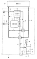
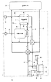
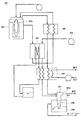
図1は、本発明の実施の形態1に係る燃料電池システムの概略構成を示す模式図である。
[Configuration of fuel cell system]
FIG. 1 is a schematic diagram showing a schematic configuration of a fuel cell system according to
図1に示すように、本発明の実施の形態1に係る燃料電池システム1は、原料供給器4、燃料電池2と水素生成器3を有する燃料電池装置24、酸化剤ガス供給器10、燃焼排ガス熱交換器5、酸化剤排ガス熱交換器11、水タンク6、貯湯タンク14、及び筐体23を備えている。筐体23には、排気口7が設けられている。
As shown in FIG. 1, a
なお、本実施の形態1においては、燃料電池装置24は、燃料電池2と水素生成器3を有する形態を採用したが、これに限定されない。燃料電池2が直接内部改質型固体酸化物形燃料電池である場合や水素ガスのインフラが整備されたような場合には、燃料電池装置24は水素生成器3を有しない形態を採用してもよい。
In the first embodiment, the
水素生成器3は、改質器(図示せず)と燃焼器3aを有している。燃焼器3aには、後述するオフ燃料ガス流路27を介して燃料電池2(正確には、燃料電池2の燃料ガス内部流路2a)が接続されている。これにより、燃焼器3aには、燃料電池2の燃料ガス内部流路2aからオフ燃料ガス等の可燃ガスが供給される。
The hydrogen generator 3 has a reformer (not shown) and a
また、燃焼器3aには、燃焼排ガス流路(排ガス流路;第3流路)8の上流端が接続されている。燃焼排ガス流路8の下流端は、排気口7に接続されている。燃焼排ガス流路8の途中には、燃焼排ガス熱交換器5が設けられている。また、燃焼排ガス流路8の燃焼排ガス熱交換器5よりも下流側の流路には、燃焼排ガス凝縮水流路(第4流路)9の上流端が接続されている。燃焼排ガス凝縮水流路9の下流端は、後述する水タンク6の第1貯水部17に接続されている。
An upstream end of a combustion exhaust gas passage (exhaust gas passage; third passage) 8 is connected to the
燃焼排ガス熱交換器5は、燃焼排ガス流路8を通流する燃焼排ガスと温水循環経路15を通流する水と熱交換するように構成されている。燃焼排ガス熱交換器5としては、例えば、全熱交換器等の各種の熱交換器を用いることができる。
The combustion exhaust
これにより、燃焼器3aでは、燃料ガス内部流路2aから供給された燃料ガス等の可燃ガスと、別途供給された燃焼用空気を燃焼して、燃焼排ガスが生成される。生成された燃焼排ガスは、改質器等を加熱した後に、燃焼排ガス流路8を通流して、排気口7から燃料電池システム1外に排出される。また、燃焼排ガス中に含まれる水分は、燃焼排ガス熱交換器5で水と熱交換することにより、水に凝縮する。凝縮した水は、燃焼排ガス凝縮水流路9を通流して、水タンク6に貯えられる。
Thereby, in the
水素生成器3には、原料供給流路25を介して原料供給器4が接続されている。原料供給器4は、水素生成器3に原料をその流量を調整しながら供給することができれば、どのような構成であってもよく、例えば、ブロワで構成されていてもよい。ここで、原料としては、メタンを主成分とする天然ガスやLPガス等を用いることができる。
A raw
水素生成器3の改質器は、改質触媒を有している。改質触媒としては、例えば、原料と水蒸気とから水素含有ガスを発生させる水蒸気改質反応を触媒することができれば、どの様な物質を使用してもよく、例えば、アルミナ等の触媒担体にルテニウム(Ru)を担持させたルテニウム系触媒や同様の触媒担体にニッケル(Ni)を担持させたニッケル系触媒等を使用することができる。 The reformer of the hydrogen generator 3 has a reforming catalyst. As the reforming catalyst, any substance may be used as long as it can catalyze a steam reforming reaction that generates a hydrogen-containing gas from a raw material and steam, for example, ruthenium on a catalyst carrier such as alumina. A ruthenium catalyst supporting (Ru) or a nickel catalyst supporting nickel (Ni) on the same catalyst carrier can be used.
そして、改質器では、原料供給器4から供給された原料と別途供給された水蒸気(水)との改質反応により、水素含有ガスが生成される。生成された水素含有ガスは、燃料ガスとして、燃料ガス供給流路26を通流して、燃料電池2の燃料ガス内部流路2aに供給される。
In the reformer, a hydrogen-containing gas is generated by a reforming reaction between the raw material supplied from the
なお、本実施の形態1においては、改質器で生成された水素含有ガスが、燃料ガスとして、燃料電池2に送出される構成としたが、これに限定されない。例えば、水素生成器3内に改質器より送出された水素含有ガス中の一酸化炭素を低減するための変成触媒(例えば、銅−亜鉛系触媒)を有する変成器や、酸化触媒(例えば、ルテニウム系触媒)や、メタン化触媒(例えば、ルテニウム系触媒)を有する一酸化炭素除去器が配置されていて、これらの機器を通過した後の水素含有ガスが燃料電池2に送出される構成であってもよい。
In the first embodiment, the hydrogen-containing gas generated in the reformer is sent to the
燃料電池2は、アノードとカソード(図3参照)を有していて、アノードに燃料ガスを供給する燃料ガス内部流路2aとカソードに酸化剤ガスを供給する酸化剤ガス内部流路2bが設けられている。燃料電池2としては、高分子電解質形燃料電池や直接内部改質型固体酸化物形燃料電池や間接内部改質型固体酸化物形燃料電池等の各種の燃料電池を用いることができる。なお、燃料電池2の具体的な構成については、後述する。
The
燃料電池2の酸化剤ガス内部流路2bの上流端には、酸化剤ガス供給流路28を介して酸化剤ガス供給器10が接続されている。酸化剤ガス供給器10は、燃料電池2の酸化剤ガス内部流路2bに酸化剤ガス(空気)を供給するように構成されていれば、どのような形態であってもよい。酸化剤ガス供給器10としては、例えば、ブロワやシロッコファン等のファン類を用いることができる。
An oxidant
また、酸化剤ガス内部流路2bの下流端には、酸化剤排ガス流路(排ガス流路)12が接続されている。酸化剤排ガス流路12は、第1酸化剤排ガス流路(第1流路)12aと第2酸化剤排ガス流路(第2流路)12bを有している。第1酸化剤排ガス流路12aは、燃料電池2の酸化剤ガス内部流路2bと水タンク6の第1貯水部17を接続している。第2酸化剤排ガス流路12bは、水タンク6の第1貯水部17と排気口7を接続している。また、第1酸化剤排ガス流路12aの途中には、酸化剤排ガス熱交換器11が設けられている。
An oxidant exhaust gas flow channel (exhaust gas flow channel) 12 is connected to the downstream end of the oxidant gas internal flow channel 2b. The oxidant exhaust
酸化剤排ガス熱交換器11は、第1酸化剤排ガス流路12aを通流する酸化剤排ガスと温水循環経路15を通流する水と熱交換するように構成されている。酸化剤排ガス熱交換器11としては、例えば、全熱交換器等の各種の熱交換器を用いることができる。
The oxidant exhaust
これにより、燃料電池2では、水素生成器3から燃料ガスが燃料ガス内部流路2aに供給され、酸化剤ガス供給器10から酸化剤ガス内部流路2bに酸化剤ガスが供給される。そして、燃料ガス内部流路2aに供給された燃料ガスが、燃料ガス内部流路2aを通流する間に、アノードに供給される。また、酸化剤ガス内部流路2bに供給された酸化剤ガスが、酸化剤ガス内部流路2bを通流する間に、カソードに供給される。アノードに供給された燃料ガスとカソードに供給された酸化剤ガスとが、反応して電気と熱が発生する。
Thereby, in the
なお、発生した電気は、図示されない電力調整器により、外部電力負荷(例えば、家庭の電気機器)に供給される。また、発生した熱は、図示されない熱媒体流路を通流する熱媒体が回収する。熱媒体が回収した熱は、例えば、温水循環経路15を通流する水を加熱するのに使用することができる。
The generated electricity is supplied to an external power load (for example, home electrical equipment) by a power regulator (not shown). The generated heat is recovered by a heat medium flowing through a heat medium flow path (not shown). The heat recovered by the heat medium can be used, for example, to heat water flowing through the hot
燃料電池2で使用されなかった燃料ガスは、オフ燃料ガスとして、水素生成器3の燃焼器3aに供給される。また、燃料電池2で使用されなかった酸化剤ガス(以下、酸化剤排ガス)は、酸化剤排ガス流路12を通流して、燃料電池システム1外に排出される。酸化剤排ガス中に含まれる水分は、酸化剤排ガス熱交換器11で水と熱交換することにより、水に凝縮する。凝縮した水は、第1酸化剤排ガス流路12aを通流して、水タンク6に貯えられる。
The fuel gas that has not been used in the
貯湯タンク14は、ここでは、鉛直方向に延びるように形成されている。貯湯タンク14の下部には、温水循環経路15の上流端が接続されていて、その下流端は、貯湯タンク14の上部に接続されている。温水循環経路15は、その途中で2本に分岐して、その後、2本に分岐した流路が合流するように構成されている。温水循環経路15の2本に分岐した流路には、燃焼排ガス熱交換器5と酸化剤排ガス熱交換器11が、それぞれ設けられている。これにより、貯湯タンク14の下部にある低温の水が、温水循環経路15を通流して、燃焼排ガス熱交換器5等により加熱されて、温水として、貯湯タンク14の上部に供給される。
Here, the hot
なお、本実施の形態1においては、温水循環経路15は、その途中で2本に分岐して、その後、2本に分岐した流路が合流するように構成したが、これに限定されない。温水循環経路15は、1本の経路で構成されていてもよい。この場合、温水循環経路15には、燃焼排ガス熱交換器5が酸化剤排ガス熱交換器11よりも上流側に設けられてもよく、酸化剤排ガス熱交換器11が燃焼排ガス熱交換器5よりも上流側に設けられてもよい。
In the first embodiment, the hot
[燃料電池の構成]
次に、図2及び図3を参照しながら、本実施の形態1に係る燃料電池システム1における燃料電池2の構成について説明する。
[Configuration of fuel cell]
Next, the configuration of the
図2は、図1に示す燃料電池システムにおける燃料電池の概略構成を示す模式図である。なお、本実施の形態1においては、燃料電池2として、高分子電解質形燃料電池(以下、PEFC)を使用しており、以下の説明では、PEFCの構成を説明する。
FIG. 2 is a schematic diagram showing a schematic configuration of the fuel cell in the fuel cell system shown in FIG. In the first embodiment, a polymer electrolyte fuel cell (hereinafter referred to as PEFC) is used as the
図2に示すように、燃料電池2は、複数のセル61がその厚み方向に積層されたセル積層体60と、該セル積層体60の両端に配置された端板62、63と、セル積層体60と端板62、63をセル61の積層方向において締結する締結具(図示せず)と、を有する。また、端板62とセル積層体60の間には、絶縁板及び集電板(いずれも図示せず)が配置されていて、端板63とセル積層体60との間には、絶縁板及び集電板(いずれも図示せず)が配置されている。
As shown in FIG. 2, the
セル積層体60には、セル61の積層方向に延びるように、燃料ガス供給マニホールド64、酸化剤ガス供給マニホールド66、燃料ガス排出マニホールド65、及び酸化剤ガス排出マニホールド67が設けられている。なお、燃料ガス供給マニホールド64には、燃料ガス供給流路26が接続されていて、燃料ガス排出マニホールド65には、オフ燃料ガス流路27が接続されている(図1参照)。また、酸化剤ガス供給マニホールド66には、酸化剤ガス供給流路28が接続されていて、酸化剤ガス排出マニホールド67には、酸化剤排ガス流路12が接続されている(図1参照)。
The
[セルの構成]
図3は、図2に示す燃料電池におけるセルの概略構成を模式的に示す断面図である。なお、図3においては、一部を省略している。
[Cell structure]
FIG. 3 is a cross-sectional view schematically showing a schematic configuration of a cell in the fuel cell shown in FIG. In FIG. 3, a part is omitted.
図3に示すように、セル61は、MEA(Membrane−Electrode−Assembly:膜−電極接合体)73と、ガスケット74と、アノードセパレータ75Aと、カソードセパレータ75Bと、を備えている。
As shown in FIG. 3, the
MEA73は、水素イオンを選択的に輸送する高分子電解質膜71と、アノード72Aと、カソード72Bと、を有している。なお、高分子電解質膜71の周縁部には、燃料ガス供給マニホールド孔(図示せず)等の各マニホールド孔が厚み方向に貫通するように設けられている。アノード72Aは、高分子電解質膜71の一方の主面上に設けられ、カソード72Bは、高分子電解質膜71の他方の主面上に設けられている。
The
また、MEA73のアノード72A及びカソード72Bの周囲には、高分子電解質膜71を挟んで一対のフッ素ゴム製でドーナツ状のガスケット74が配設されている。これにより、燃料ガスや酸化剤ガスが電池外にリークされることが防止され、また、セル61内でこれらのガスが互いに混合されることが防止される。なお、ガスケット74の周縁部には、厚み方向の貫通孔からなる燃料ガス供給マニホールド孔(図示せず)等の各マニホールド孔が設けられている。
A pair of fluorine rubber doughnut-shaped
また、MEA73とガスケット74を挟むように、導電性のアノードセパレータ75Aとカソードセパレータ75Bが配設されている。これにより、MEA73が機械的に固定され、複数のセル61をその厚み方向に積層したときには、MEA73が電気的に接続される。なお、これらのセパレータ75A、75Bは、熱伝導性及び導電性に優れた金属、黒鉛、又は、黒鉛と樹脂を混合したものを使用することができ、例えば、カーボン粉末とバインダー(溶剤)との混合物を射出成形により作製したものやチタンやステンレス鋼製の板の表面に金メッキを施したものを使用することができる。
Further, a
アノードセパレータ75Aのアノード72Aと接触する一方の主面(以下、内面という)には、燃料ガスが通流するための溝状の燃料ガス流路77が設けられている。同様に、カソードセパレータ75Bのカソード72Bと接触する一方の主面(以下、内面という)には、酸化剤ガスが通流するための溝状の酸化剤ガス流路78が設けられている。なお、アノードセパレータ75A及びカソードセパレータ75Bのそれぞれの周縁部には、燃料ガス供給マニホールド孔(図示せず)等の各マニホールド孔が厚み方向に貫通するように設けられている。また、燃料ガス流路77及び酸化剤ガス流路78の形状は任意であり、例えば、セル61の厚み方向から見て、サーペンタイン状に形成されていてもよく、ストレート形状に形成されていてもよい。
On one main surface (hereinafter referred to as an inner surface) of the
そして、このように形成されたセル61がその厚み方向に積層されることにより、セル積層体60が形成される。このとき、高分子電解質膜71等に設けられた燃料ガス供給マニホールド孔(図示せず)等の各マニホールド孔がつながって、燃料ガス供給マニホールド64等の各マニホールドが形成される(図2参照)。なお、燃料ガス供給マニホールド64、燃料ガス流路77、及び燃料ガス排出マニホールド65から燃料ガス内部流路2aが構成される。また、酸化剤ガス供給マニホールド66、酸化剤ガス流路78、酸化剤ガス排出マニホールド67から酸化剤ガス内部流路2bが構成される。
And the cell laminated
[水タンクの構成]
次に、本実施の形態1に係る燃料電池システム1における水タンク6の構成について、図1及び図4を参照しながら詳細に説明する。
[Configuration of water tank]
Next, the configuration of the
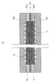
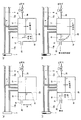
図4は、図1に示す燃料電池システムにおける水タンク周辺の概略構成を示す模式図である。図4(a)は、燃焼排ガス流路8の水タンク6よりも下流側の流路(燃焼排ガス流路8の燃焼排ガス凝縮水流路9が接続されている部分よりも下流側の流路)及び酸化剤排ガス流路12の第2酸化剤排ガス流路12bが、閉塞されていない状態を示し、図4(b)〜(d)は、燃焼排ガス流路8の水タンク6よりも下流側の流路及び第2酸化剤排ガス流路12bの少なくとも一方の流路が、閉塞されている状態を示す。
FIG. 4 is a schematic diagram showing a schematic configuration around the water tank in the fuel cell system shown in FIG. 1. 4A shows a flow path downstream of the
図4に示すように、本実施の形態1に係る燃料電池システム1の水タンク6は、第1貯水部17と、第2貯水部18と、該水タンク6の下部で第1貯水部17と第2貯水部18とを連通するように構成された連通部29を有している。具体的には、水タンク6には、その内部空間を分けるように隔壁16が設けられている。隔壁16は、水タンク6の天井面から下方に延びるように、かつ、水タンク6の底面と隙間を有するように、形成されている。そして、隔壁16と水タンク6の底面との間の空間が、連通部29を構成する。
As shown in FIG. 4, the
また、水タンク6の第1貯水部17には、水供給流路30が接続されている。水供給流路30は、市水が通流するように構成されていて、その途中には、給水弁(水供給器)21が設けられている。給水弁21は、水供給流路30内の市水の通流を許可/阻止するように構成されている。給水弁21としては、開閉弁等の各種の弁を使用することができる。
A water
さらに、水タンク6の第2貯水部18には、連通部29よりも上方に排水口20が設けられている。排水口20には、排水流路31の上流端が接続されていて、その下流端は、ホッパーにおいて、燃料電池システム1外(大気)に開放されており、かつ、一端が下水道につながっている下水管に接続されている。
Further, the second
水タンク6の第2貯水部18における排水口20が設けられる位置(高さ)は、燃焼排ガス流路8の水タンク6よりも下流側の流路及び第2酸化剤排ガス流路12bの少なくとも一方の流路が閉塞された場合に、第1貯水部17内のガスが排水口20より大気中に排出されるときの第1貯水部17内の圧力が、燃料電池2の耐圧以下となるように設定されている。換言すると、隔壁16の上端から排水口20の下端までの高さH(図4(a)参照)に対応する水圧差が燃料電池2の耐圧よりも小さくなるように、排水口20及び隔壁16が水タンク6に設けられている。
The position (height) at which the
ここで、「燃料電池2の耐圧」とは、燃料電池2の破損を防止することが保証できる最大の圧力をいい、各マニホールド(マニホールド孔)内に存在するガスの圧力により、ガスケット74のシール性が損なわれる圧力及びセパレータ75A、75Bが破損する圧力のうち、小さい方の圧力をいう。そして、高さH(mm)は、燃料電池2の耐圧をAkPaとした場合、1kPa=102mmH2Oであるため、A×102mmとなる。したがって、排水口20及び隔壁16は、隔壁16の上端から排水口20の下端までの高さHが、A×102mmよりも小さくなるように、水タンク6に配設されていることが好ましい。
Here, the “pressure resistance of the
なお、本実施の形態1においては、排水口20及び隔壁16は、隔壁16の上端から排水口20の下端までの高さHに対応する水圧差が燃料電池2の耐圧よりも小さくなるように水タンク6に配設されている形態を採用したが、これに限定されない。例えば、排水口20及び隔壁16は、隔壁16の上端から排水口20の下端までの高さHに対応する水圧差が水素生成器3の耐圧よりも小さくなるように水タンク6に配設されている形態を採用してもよい。また、例えば、排水口20及び隔壁16は、隔壁16の上端から排水口20の下端までの高さHに対応する水圧差が、燃料電池2の耐圧及び水素生成器3の耐圧のうち、小さい方の圧力よりも小さくなるように水タンク6に配設されている形態を採用してもよい。
In the first embodiment, the
さらに、例えば、排水口20及び隔壁16は、隔壁16の上端から排水口20の下端までの高さHに対応する水圧差が、原料供給器4及び酸化剤ガス供給器10の少なくとも一方の締結圧よりも小さくなるように、水タンク6に配設されている形態を採用してもよい。この場合、排水口20及び隔壁16は、隔壁16の上端から排水口20の下端までの高さHに対応する水圧差が、原料供給器4の締結圧及び酸化剤ガス供給器10の締結圧のうち、小さい方の圧力よりも小さくなるように水タンク6に配設されている形態を採用することが好ましく、燃料電池2の耐圧、水素生成器3の耐圧、原料供給器4の締結圧、及び酸化剤ガス供給器10の締結圧のうち、最も小さい圧力よりも小さくなるように水タンク6に配設されている形態を採用することがより好ましい。なお、本実施の形態1においては、排水口20及び隔壁16は、隔壁16の上端から排水口20の下端までの高さHに対応する水圧差が、燃料電池2の耐圧、水素生成器3の耐圧、原料供給器4の締結圧、及び酸化剤ガス供給器10の締結圧のうち、最も小さい圧力よりも小さくなるように水タンク6に配設されている形態を採用している。
Further, for example, the
これにより、燃焼排ガス流路8の水タンク6よりも下流側の流路及び第2酸化剤排ガス流路12bの少なくとも一方の流路が閉塞された場合に、酸化剤排ガス流路12の第1酸化剤排ガス流路12aを通流する酸化剤排ガス及び燃焼排ガス流路8を通流する燃焼排ガスは、水タンク6の排水口20を介して、大気中に排出される。なお、燃焼排ガス流路8、第1酸化剤排ガス流路12a及び第2酸化剤排ガス流路12bは、圧力損失が大きくならないように、内径が充分に大きい配管が用いられている。
Thereby, when at least one of the flow path downstream of the
[燃料電池システムの動作]
次に、本実施の形態1に係る燃料電池システム1の動作について、図1を参照しながら説明する。なお、以下の説明においては、燃焼排ガス流路8の水タンク6よりも下流側の流路及び第2酸化剤排ガス流路12bの少なくとも一方の流路が閉塞されていない場合について説明する。
[Operation of fuel cell system]
Next, the operation of the
まず、水素生成器3に天然ガス、LPG等の原料が原料供給器4により供給される。水素生成器3では、供給された原料が水蒸気雰囲気化で水蒸気改質され、水素を多く含む燃料ガスが生成される。生成された燃料ガスは、燃料電池2のアノード72Aに供給される。また、燃料電池2のカソード72Bには、酸化剤ガス供給器10によって、空気が酸化剤ガスとして供給される。
First, raw materials such as natural gas and LPG are supplied to the hydrogen generator 3 by the
燃料電池2では、このようにして供給された燃料ガスと酸化剤ガスとを用いて反応が行われ、電気と熱が発生する。発生した熱は、燃料電池2を通流する冷却水に回収される(図示せず)。
In the
反応に利用されずに燃料電池2から排出された未反応の燃料ガスは、水素生成器3の燃焼器3aに供給され、燃焼に用いられる。燃焼器3aで生じる燃焼熱により水素生成器3の改質器等(図示せず)が加熱される。これにより、改質器を所定の温度に保った状態で水蒸気改質反応を行うことができる。
Unreacted fuel gas discharged from the
そして、燃焼器3aで生成された燃焼排ガスは、燃焼排ガス流路8に排出される。燃焼排ガス流路8に排出された燃焼排ガスは、燃焼排ガス熱交換器5で温水循環経路15を通流する水によって、燃焼排ガスの熱が回収される。これにより、燃焼排ガスが露点温度以下にまで冷却され、燃焼排ガス中の水分が凝縮される。凝縮された水は、燃焼排ガス凝縮水流路9を通流して、水タンク6に貯えられる。なお、燃焼排ガスの気体成分は、燃焼排ガス流路8を通流して、排気口7から燃料電池システム1外に放出される。
Then, the combustion exhaust gas generated by the
また、反応に利用されずに燃料電池2から排出された未反応の酸化剤排ガスは、酸化剤排ガス流路12(正確には、第1酸化剤排ガス流路12a)を通流して、酸化剤排ガス熱交換器11に送られる。酸化剤排ガス熱交換器11では、温水循環経路15を通流する水によって、酸化剤排ガスの熱が回収される。これにより、酸化剤排ガスが露点温度以下まで冷却され、それにより、酸化剤排ガス中の水分が凝縮される。凝縮された水は、第1酸化剤排ガス流路12aを通流して、水タンク6に貯えられる。また、酸化剤排ガスの気体成分は、第2酸化剤排ガス流路12bを通流して、排気口7から燃料電池システム1外に放出される。
Further, the unreacted oxidant exhaust gas discharged from the
[燃料電池システムの作用効果]
次に、本実施の形態1に係る燃料電池システム1の作用効果について、図1及び図4(b)〜(d)を参照しながら説明する。
[Function and effect of fuel cell system]
Next, the operation and effect of the
図4(b)〜(d)に示すように、燃料電池システム1の運転中等に、燃焼排ガス流路8の水タンク6よりも下流側の流路及び第2酸化剤排ガス流路12bの少なくとも一方の流路が閉塞されたとする(図4(b)〜(d)では、排気口7が閉塞されている状態を示している)。排気口7が次第に閉塞すると、排気口7での燃焼排ガスと酸化剤排ガスの圧力損失が増加する。これに伴い、燃焼排ガス流路8及び第2酸化剤排ガス流路12b内の圧力が増加し、ひいては、水タンク6の第1貯水部17内の圧力が増加する。
As shown in FIGS. 4B to 4D, during operation of the
図4(b)に示すように、第1貯水部17内の圧力増加に伴い、水タンク6の第1貯水部17の水位が低下する。一方、第2貯水部18の水位は、第1貯水部17の水位が低下した分だけ上昇する。図4(c)に示すように、第2貯水部18の水位が排水口20より高くなると、水タンク6内の水は、排水口20から排水流路31を通流して、燃料電池システム1外に排水される。
As shown in FIG. 4 (b), the water level of the
そして、図4(d)に示すように、排気口7がさらに閉塞すると、排気口7での燃焼排ガスと酸化剤排ガスの圧力損失はさらに増加する。このため、第1貯水部17の圧力がさらに増加し、水タンク6の第1貯水部17の水位はさらに低くなる。第1貯水部17の水位が隔壁16より低くなると、第1貯水部17内のガス(空気、酸化剤排ガス及び燃焼排ガスを含む)は、第2貯水部18に進入する。第2貯水部18に進入したガスは、第2貯水部18から排水口20を介して、排水流路31を通流して、燃料電池システム1外(大気中)に排出される。したがって、水タンク6の第1貯水部17内の圧力が、燃料電池2及び水素生成器3の耐圧のうち、小さい方の圧力以上になることが抑制される。
Then, as shown in FIG. 4D, when the
このように、本実施の形態1に係る燃料電池システム1では、燃焼排ガス流路8の水タンク6よりも下流側の流路及び第2酸化剤排ガス流路12bの少なくとも一方の流路が閉塞されても、第1貯水部17内の圧力が、燃料電池2の耐圧、水素生成器3の耐圧、原料供給器4の締結圧、及び酸化剤ガス供給器10の締結圧のうち、最も小さい圧力以上になることが抑制されるため、燃料電池2、水素生成器3、原料供給器4、及び酸化剤ガス供給器10の破損を抑制することができる。
Thus, in the
なお、本実施の形態1においては、排ガス流路を酸化剤排ガス流路12と燃焼排ガス流路8及び燃焼排ガス凝縮水流路9で構成される形態を採用したが、これに限定されない。排ガス流路は、例えば、酸化剤排ガス流路12で構成されてもよく、燃焼排ガス流路8及び燃焼排ガス凝縮水流路9で構成されてもよい。
In the first embodiment, the exhaust gas flow path is composed of the oxidant exhaust
また、本実施の形態1においては、燃焼排ガス流路8の水タンク6よりも下流側の流路及び第2酸化剤排ガス流路12bの少なくとも一方の流路が閉塞された場合に、燃料電池システム1の運転を継続してもよく、後述する実施の形態2のように、燃料電池システム1の運転を停止させてもよい。
In the first embodiment, when at least one of the flow path downstream of the
[変形例1]
次に、本実施の形態1に係る燃料電池システム1の変形例について説明する。
[Modification 1]
Next, a modification of the
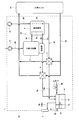
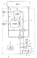
図5は、本実施の形態1における変形例1の燃料電池システムの概略構成を示す模式図である。
FIG. 5 is a schematic diagram showing a schematic configuration of a fuel cell system according to
図5に示すように、本実施の形態1における変形例1の燃料電池システム1は、実施の形態1に係る燃料電池システム1と基本的構成は同じであるが、排ガス流路(燃焼排ガス流路8及び酸化剤排ガス流路12)の構成が異なる。具体的には、燃焼排ガス流路8は、第1燃焼排ガス流路(第1流路)8aと第2燃焼排ガス流路(第2流路)8bを有している。第1燃焼排ガス流路8aは、水素生成器3の燃焼器3aと水タンク6の第1貯水部17を接続している。第2燃焼排ガス流路8bは、水タンク6の第1貯水部17と排気口7を接続している。
As shown in FIG. 5, the
また、酸化剤排ガス流路(第3流路)12は、燃料電池2の酸化剤ガス内部流路2bと排気口7を接続している。また、酸化剤排ガス流路12の酸化剤排ガス熱交換器11よりも下流側の流路には、酸化剤排ガス凝縮水流路(第4流路)13の上流端が接続されている。酸化剤排ガス凝縮水流路13の下流端は、水タンク6の第1貯水部17に接続されている。
The oxidant exhaust gas flow path (third flow path) 12 connects the oxidant gas internal flow path 2 b of the
このように構成された本変形例1の燃料電池システム1であっても、実施の形態1に係る燃料電池システム1と同様の作用効果を奏する。
Even the
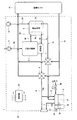
[変形例2]
図6は、本実施の形態1における変形例2の燃料電池システムの概略構成を示す模式図である。
[Modification 2]
FIG. 6 is a schematic diagram showing a schematic configuration of a fuel cell system according to
図6に示すように、本実施の形態1における変形例2の燃料電池システム1は、実施の形態1に係る燃料電池システム1と基本的構成は同じであるが、燃焼排ガス流路8の構成が異なる。具体的には、燃焼排ガス流路8は、第1燃焼排ガス流路(第1流路)8aと第2燃焼排ガス流路(第2流路)8bを有している。第1燃焼排ガス流路8aは、水素生成器3の燃焼器3aと水タンク6の第1貯水部17を接続している。第2燃焼排ガス流路8bは、水タンク6の第1貯水部17と排気口7を接続している。そして、本変形例2においては、第2燃焼排ガス流路8bを構成する配管が、第2酸化剤排ガス流路12bを兼用している。
As shown in FIG. 6, the
このように構成された本変形例2の燃料電池システム1であっても、実施の形態1に係る燃料電池システム1と同様の作用効果を奏する。なお、本変形例2においては、第2燃焼排ガス流路8bと第2酸化剤排ガス流路12bとを兼用する形態を採用したが、これに限定されず、第2燃焼排ガス流路8bと第2酸化剤排ガス流路12bを別々に設ける形態を採用してもよい。
Even the
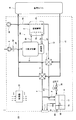
[変形例3]
図7は、本実施の形態1における変形例3の燃料電池システムの概略構成を示す模式図である。
[Modification 3]
FIG. 7 is a schematic diagram showing a schematic configuration of a fuel cell system according to Modification 3 of
図7に示すように、本実施の形態1における変形例3の燃料電池システム1は、実施の形態1に係る燃料電池システム1と基本的構成は同じであるが、酸化剤排ガス流路12の構成が異なる。具体的には、酸化剤排ガス流路(第3流路)12は、燃料電池2の酸化剤ガス内部流路2bと排気口7を接続している。また、酸化剤排ガス流路12の酸化剤排ガス熱交換器11よりも下流側の流路には、酸化剤排ガス凝縮水流路(第4流路)13の上流端が接続されている。酸化剤排ガス凝縮水流路13の下流端は、水タンク6の第1貯水部17に接続されている。
As shown in FIG. 7, the
このように構成された本変形例3の燃料電池システム1であっても、実施の形態1に係る燃料電池システム1と同様の作用効果を奏する。
Even the
[変形例4]
図8は、本実施の形態1における変形例4の燃料電池システムの概略構成を示す模式図である。
[Modification 4]
FIG. 8 is a schematic diagram showing a schematic configuration of a fuel cell system according to
図8に示すように、本実施の形態1における変形例4の燃料電池システム1は、実施の形態1に係る燃料電池システム1と基本的構成は同じであるが、水タンク6の構成が異なる。具体的には、第1貯水部17と第2貯水部18が、それぞれ、独立したタンク(筐体)で構成されている。そして、第1貯水部17の下部と第2貯水部18の下部を連通するように、連通部29が設けられている。
As shown in FIG. 8, the basic configuration of the
このように構成された本変形例4の燃料電池システム1であっても、実施の形態1に係る燃料電池システム1と同様の作用効果を奏する。
Even the
(実施の形態2)
本発明の実施の形態2に係る燃料電池システムは、制御器と、水タンクの第1貯水部に設けられ、該第1貯水部の水位を検知する水位検知器と、をさらに備え、排ガスが水タンクの排水口を介して大気中に排出される場合の水位である第1水位を水位検知器が検知した場合に、制御器が燃料電池装置の運転を停止するように構成されている態様を例示するものである。
(Embodiment 2)
The fuel cell system according to
[燃料電池システムの構成]
図9は、本発明の実施の形態2に係る燃料電池システムの概略構成を示す模式図である。
[Configuration of fuel cell system]
FIG. 9 is a schematic diagram showing a schematic configuration of a fuel cell system according to
図9に示すように、本発明の実施の形態2に係る燃料電池システム1は、実施の形態1に係る燃料電池システム1と基本的構成は同じであるが、水位検知器19及び制御器22が設けられている点が異なる。具体的には、水位検知器19は、水タンク6の第1貯水部17内に設けられている。
As shown in FIG. 9, the
水位検知器19は、第1貯水部17内部の水位を検知し、その検知した水位を制御器22に出力することができればどの様な形態であってもよい。水位検知器19としては、例えば、例えば、フロート式水位センサ、光学界面式水位センサ、超音波式水位センサ、電極式水位センサ、及び圧力式水位センサ等を用いることができる。
The
制御器22は、燃料電池システム1を構成する各機器を制御する機器であれば、どのような形態であってもよく、例えば、マイクロプロセッサ、CPU等に例示される演算処理部と、各制御動作を実行するためのプログラムを格納した、メモリ等から構成される記憶部を備えている。そして、制御器22は、演算処理部が、記憶部に格納された所定の制御プログラムを読み出し、これを実行することにより、これらの情報を処理し、かつ、これらの制御を含む燃料電池システム1に関する各種の制御を行う。
The
なお、制御器22は、単独の制御器で構成される形態だけでなく、複数の制御器が協働して、燃料電池システム1の制御を実行する制御器群で構成される形態であっても構わない。また、制御器22は、マイクロコントローラで構成されていてもよく、MPU、PLC(Programmable Logic Controller)、論理回路等によって構成されていてもよい。
The
そして、制御器22は、水位検知器19が検知する第1貯水部17の水位に基づいて、燃料電池システム1の制御を行う。具体的には、制御器22は、水位検知器19が第1水位を検知すると、燃料電池装置24(燃料電池システム1)の運転を停止させる。ここで、第1水位は、燃焼排ガス流路8の水タンク6よりも下流側の流路及び第2酸化剤排ガス流路12bの少なくとも一方の流路が閉塞され、排ガスが水タンク6の排水口20を介して大気中に排出されるときの水位である。
The
例えば、燃料電池2の耐圧をAkPaとした場合、第1貯水部17の水位が排水口20からA×102mm下方に位置するときに、排水口20から排ガスが排出されると、燃料電池2の破損を抑制することができる。このため、制御器22は、水位検知器19が排水口20からA×102mm以下の水位を検知した場合に、燃料電池システム1を停止させることが好ましい。したがって、第1水位は、排水口20からA×102mm下方の位置以下、かつ、水タンク6の底面以上の間で任意に設定することができる。
For example, when the pressure resistance of the
このように構成された、本実施の形態2に係る燃料電池システム1であっても、実施の形態1に係る燃料電池システム1と同様の作用効果を奏する。
Even the
また、本実施の形態2に係る燃料電池システム1では、水位検知器19が第1水位を検知すると、制御器22が燃料電池システム1の運転を停止するように構成されているため、燃焼排ガス流路8の水タンク6よりも下流側の流路及び第2酸化剤排ガス流路12bの少なくとも一方の流路が閉塞されても、燃料電池2に耐圧以上の圧力がかかることが抑制される。このため、本実施の形態2に係る燃料電池システム1では、燃料電池2の破損を充分に抑制することができる。
Further, in the
なお、本実施の形態2においては、第1水位を燃料電池2の耐圧に基づいて規定したが、これに限定されない。例えば、第1水位は、水素生成器3の耐圧に基づいて規定してもよく、原料供給器4の締結圧に基づいて規定してもよく、酸化剤ガス供給器10の締結圧に基づいて規定してもよい。また、第1水位は、燃料電池2の耐圧、水素生成器3の耐圧、原料供給器4の締結圧、及び酸化剤ガス供給器10の締結圧のうち、最も小さい圧力に基づいて規定してもよい。
In the second embodiment, the first water level is defined based on the pressure resistance of the
(実施の形態3)
本発明の実施の形態3に係る燃料電池システムは、制御器と、水タンクの第1貯水部に設けられ、該第1貯水部の水位を検知する水位検知器と、水タンクの第1貯水部に水を供給するように構成された水供給器と、をさらに備え、制御器が、排ガスが水タンクの排水口を介して大気中に排出される場合の水位である第1水位よりも高く、かつ、第1貯水部の満水位よりも低い水位である第2水位を水位検知器が検知した場合に、水タンクの第1貯水部に水を供給するように水供給器を制御し、水供給器が第1貯水部に水を供給してから所定時間経過後に、水位検知器が第1水位を検知した場合に、燃料電池装置の運転を停止するように構成されている態様を例示するものである。
(Embodiment 3)
The fuel cell system according to Embodiment 3 of the present invention includes a controller, a water level detector that is provided in the first water storage part of the water tank and detects the water level of the first water storage part, and the first water storage of the water tank. And a water supply device configured to supply water to the section, wherein the controller is higher than a first water level that is a water level when exhaust gas is discharged into the atmosphere through the drain of the water tank. When the water level detector detects a second water level that is high and lower than the full water level of the first water reservoir, the water supplier is controlled to supply water to the first water reservoir of the water tank. A mode in which the operation of the fuel cell device is stopped when the water level detector detects the first water level after a predetermined time has elapsed since the water supply unit supplied water to the first water storage unit. This is just an example.
[燃料電池システムの動作]
本発明の実施の形態3に係る燃料電池システム1は、実施の形態2に係る燃料電池システム1の構成と同じであるため、その詳細な説明は省略する。また、本実施の形態3に係る燃料電池システム1の発電運転は、公知の燃料電池システム1の一般的な発電運転と同様に行われるため、その詳細な説明は省略する。
[Operation of fuel cell system]
Since the
ところで、燃料電池システム1において、例えば、燃焼排ガス熱交換器5や酸化剤排ガス熱交換器11で充分な水が凝縮されず、水タンク6内に貯えられた水の一部を別のタンクに供給するような場合には、水タンク6に貯えられている水が減少し、第1貯水部17の水位が低下する。すなわち、燃焼排ガス流路8の水タンク6よりも下流側の流路及び第2酸化剤排ガス流路12bの少なくとも一方の流路が閉塞の有無にかかわらず、第1貯水部17の水位が低下する場合がある。
Incidentally, in the
そこで、本実施の形態3においては、制御器22が、第1貯水部17の水位の低下が、流路の閉塞によるものであるのか、又は水タンク6の水を使用すること等の流路の閉塞以外によるものであるのかを判断して、流路の閉塞により第1貯水部17の水位が低下している場合には、燃料電池装置24(燃料電池システム1)の運転を停止するように構成されている。以下には、水位検知器19が検知した第1貯水部17の水位に基づく、制御器22の制御について説明する。
Therefore, in the third embodiment, the
図10は、本発明の実施の形態3に係る燃料電池システムの水位判定動作を模式的に示すフローチャートである。なお、以下の動作は、原則として、燃料電池システム1の発電運転中に行われる。
FIG. 10 is a flowchart schematically showing the water level determination operation of the fuel cell system according to Embodiment 3 of the present invention. The following operation is performed during the power generation operation of the
図10に示すように、まず、制御器22は、水位検知器19より、第1貯水部17の水位Lを取得する(ステップS101)。ついで、制御器22は、ステップS101で取得した水位Lが第2水位以下であるか否かを判断する(ステップS102)。ここで、第2水位は、第1水位よりも高く、かつ、水タンク6の満水位よりも低い水位をいう。第2水位としては、第1水位より高く、かつ、水タンク6の満水位よりも低い水位の間で任意に設定することができる。
As shown in FIG. 10, first, the
制御器22は、ステップS101で取得した水位Lが第2水位より高い場合(ステップS102でNo)には、ステップS101に戻り、第2水位以下になるまで、ステップS101及びステップS102を繰り返す。一方、制御器22は、ステップS101で取得した水位Lが第2水位以下である場合(ステップS102でYes)には、ステップS103に進む。
When the water level L acquired in step S101 is higher than the second water level (No in step S102), the
ステップS103では、制御器22は、給水弁21を作動させて、水タンク6内に市水を供給させる。なお、水タンク6への市水の供給は、第1貯水部17の水位が第2水位より高く、かつ、水タンク6の満水位以下となるように行われる。
In step S <b> 103, the
次に、制御器22は、給水弁21を作動させてからの時間Tを取得し(ステップS104)、ステップS104で取得した時間Tが、所定時間T1以上であるか否かを判断する(ステップS105)。ここで、所定時間T1は、予め実験等で求められた時間である。
Next, the
例えば、燃焼排ガス流路8の水タンク6よりも下流側の流路及び第2酸化剤排ガス流路12bの少なくとも一方の流路を閉塞させ、燃料電池2の耐圧と同じ圧力を第1貯水部17にかけたときに、第1酸化剤排ガス流路12aや燃焼排ガス流路8に存在するガスが、排水口20から排出されるまでの時間を所定時間T1としてもよい。
For example, at least one of the flow path downstream of the
また、例えば、燃焼排ガス流路8の水タンク6よりも下流側の流路及び第2酸化剤排ガス流路12bの少なくとも一方の流路を閉塞させ、燃料電池2の耐圧、水素生成器3の耐圧、原料供給器4の締結圧、及び酸化剤ガス供給器10の締結圧のうち、最も小さい圧力を第1貯水部17にかけたときに、第1酸化剤排ガス流路12aや燃焼排ガス流路8に存在するガスが、排水口20から排出されるまでの時間を所定時間T1としてもよい。
Further, for example, at least one of the flow path downstream of the
制御器22は、ステップS104で取得した時間Tが、所定時間T1未満である場合(ステップS105でNo)には、ステップS104に戻り、ステップS104で取得した時間Tが所定時間T1になるまで、ステップS104及びステップS105を繰り返す。一方、制御器22は、ステップS104で取得した時間Tが、所定時間T1以上である場合(ステップS105でYes)には、ステップS106に進む。
When the time T acquired in step S104 is less than the predetermined time T1 (No in step S105), the
ステップS106では、制御器22は、再び水位検知器19から第1貯水部17の水位を取得する。そして、制御器22は、ステップS106で取得した水位Lが第1水位以下であるか否かを判断する(ステップS107)。
In step S <b> 106, the
ここで、ステップS106で取得した水位Lが第1水位より高い場合には、水タンク6内の水が消費(供給)されたために、第1貯水部17の水位が低下したと判断することができる。一方、ステップS106で取得した水位Lが第1水位以下である場合には、燃焼排ガス流路8の水タンク6よりも下流側の流路及び第2酸化剤排ガス流路12bの少なくとも一方の流路が閉塞したために、排水口20から第1貯水部17内の水が排出され、第1貯水部17の水位が低下したと判断することができる。
Here, when the water level L acquired in step S106 is higher than the first water level, it is determined that the water level in the first
このため、制御器22は、ステップS106で取得した水位Lが第1水位より高い場合(ステップS107でNo)には、ステップS101に戻り、本プログラムを繰り返す。一方、制御器22は、ステップS106で取得した水位Lが第1水位以下である場合(ステップS107でYes)には、燃料電池装置24(燃料電池システム1)の運転を停止させ(ステップS108)、本プログラムを終了する。
For this reason, when the water level L acquired in step S106 is higher than the first water level (No in step S107), the
このように構成された本実施の形態3に係る燃料電池システム1であっても、実施の形態2に係る燃料電池システム1と同様の作用効果を奏する。また、本実施の形態3に係る燃料電池システム1では、第1貯水部17の水位の低下が、燃焼排ガス流路8の水タンク6よりも下流側の流路及び第2酸化剤排ガス流路12bの少なくとも一方の流路の閉塞によるものか否かを制御器22が判断することにより、より適切に燃料電池装置24の停止を行うことができる。このため、本実施の形態3に係る燃料電池システム1は、より利便性を高めることができる。
Even the
(実施の形態4)
本発明の実施の形態4に係る燃料電池システムは、制御器と、燃料電池装置に原料を供給する原料供給器と、を備え、燃料電池装置は、燃料電池を有し、燃料電池には、アノードに燃料ガスを供給する燃料ガス内部流路とカソードに酸化剤ガスを供給する酸化剤ガス内部流路が設けられ、燃料ガス内部流路の下流端に、排ガス流路が接続されており、制御器が、燃料電池の発電量に応じた規定流量の原料を供給するように原料供給器をフィードバック制御しており、原料供給器の供給能力が予め設定された第1供給能力よりも高くなる場合には、燃料電池装置の運転を停止するように構成されている態様を例示するものである。
(Embodiment 4)
A fuel cell system according to
ここで、「第1供給能力」は、水素生成器の耐圧及び燃料電池の耐圧のうち、小さい方の圧力よりも小さい圧力となる原料供給器の供給能力をいう。 Here, the “first supply capacity” refers to the supply capacity of the raw material supplier that has a pressure smaller than the smaller one of the pressure resistance of the hydrogen generator and the pressure resistance of the fuel cell.
[燃料電池システムの構成]
図11は、本発明の実施の形態4に係る燃料電池システムの概略構成を示す模式図である。
[Configuration of fuel cell system]
FIG. 11 is a schematic diagram showing a schematic configuration of a fuel cell system according to
図11に示すように、本発明の実施の形態4に係る燃料電池システム1は、実施の形態1に係る燃料電池システム1と基本的構成は同じであるが、制御器22が設けられている点が異なる。また、本実施の形態4に係る燃料電池システム1では、排ガス流路として、燃焼排ガス流路8及び燃焼排ガス凝縮水流路9を規定している点が、実施の形態1に係る燃料電池システム1と異なる。なお、制御器22は、実施の形態2で説明した制御器22と同様に構成されているため、その詳細な説明は省略する。
As shown in FIG. 11, the
[燃料電池システムの作用効果]
次に、本実施の形態4に係る燃料電池システム1の作用効果について説明する。
[Function and effect of fuel cell system]
Next, functions and effects of the
上述したように、燃焼排ガス流路8の水タンク6よりも下流側の流路及び第2酸化剤排ガス流路12bの少なくとも一方の流路が閉塞された場合には、水タンク6の第1貯水部17内の圧力が増加する。第1貯水部17内の圧力の増加に伴い、燃焼排ガス流路8等内の圧力が増加するため、原料供給流路25内の圧力も増加する。
As described above, when at least one of the flow path downstream from the
ここで、制御器22が、燃料電池2の発電量に応じた規定流量の原料を供給するように原料供給器4をフィードバック制御しているとする。燃料電池2の発電量が一定である場合であっても、原料供給流路25内の圧力が増加すると、原料供給器4の供給能力が一定であると、燃料電池2の発電量に応じた規定流量の原料を供給することができなくなる。
Here, it is assumed that the
このため、制御器22は、その供給能力を増加するように、原料供給器4を制御する。したがって、燃料電池2の発電量によっては、制御器22は、燃料電池2や水素生成器3の耐圧以上の圧力がかかるまで、原料供給器4の供給能力を増加させるおそれがある。
For this reason, the
そこで、本実施の形態4に係る燃料電池システム1では、制御器22が、燃料電池2の発電量に応じた規定流量の原料を供給するように、原料供給器4をフィードバック制御している場合に、原料供給器4の供給能力が予め設定された第1供給能力よりも高くなる場合には、燃料電池装置24(燃料電池システム1)の運転を停止するように構成されている。
Therefore, in the
具体的には、例えば、原料供給器4の供給能力が80%以上では、燃料電池2や水素生成器3の耐圧以上になり、燃料電池2や水素生成器3が破損するおそれがあるとする。このとき、第1供給能力を80%から10ポイント低い70%と規定したとする。制御器22は、原料供給器4の供給能力が70%よりも高くなるように、原料供給器4を制御したとき、燃焼排ガス流路8の水タンク6よりも下流側の流路及び第2酸化剤排ガス流路12bの少なくとも一方の流路が閉塞されていると判断し、燃料電池装置24の運転を停止する。このため、燃料電池2や水素生成器3が破損されることを抑制することができる。
Specifically, for example, when the supply capacity of the
このように構成された本実施の形態4に係る燃料電池システム1であっても、実施の形態1に係る燃料電池システム1と同様の作用効果を奏する。また、本実施の形態4に係る燃料電池システム1では、原料供給器4の供給能力が予め設定された第1供給能力よりも高くなると、燃料電池装置24(燃料電池システム1)の運転を停止するため、燃料電池2や水素生成器3の破損をより抑制することができる。
Even the
なお、本実施の形態4においては、制御器22が、燃料電池2の発電量に応じた規定流量の原料を供給するように原料供給器4をフィードバック制御しているとしたが、これに限定されない。例えば、制御器22は、原料の流量を測定する原料流量計で原料の流量が規定流量になるようにフィードバック制御してもよい。
In the fourth embodiment, the
(実施の形態5)
本発明の実施の形態5に係る燃料電池システムは、制御器と、燃料電池装置に原料を供給する原料供給器と、記原料供給器から燃料電池装置に供給される原料の流量を検知する原料流量検知器と、を備え、燃料電池装置は、燃料電池を有し、燃料電池には、アノードに燃料ガスを供給する燃料ガス内部流路とカソードに酸化剤ガスを供給する酸化剤ガス内部流路が設けられ、燃料ガス内部流路の下流端に、排ガス流路が接続されており、制御器は、燃料電池の発電量に応じて予め設定された供給能力になるように原料供給器を制御しており、原料流量検知器が予め設定された第1原料流量より低い流量を検知した場合には、燃料電池装置の運転を停止するように構成されている態様を例示するものである。
(Embodiment 5)
A fuel cell system according to
[燃料電池システムの構成]
図12は、本発明の実施の形態5に係る燃料電池システムの概略構成を示す模式図である。
[Configuration of fuel cell system]
FIG. 12 is a schematic diagram showing a schematic configuration of a fuel cell system according to
図12に示すように、本発明の実施の形態5に係る燃料電池システム1は、実施の形態1に係る燃料電池システム1と基本的構成は同じであるが、制御器22と原料流量計(原料流量検知器)32が設けられている点が異なる。また、本実施の形態5係る燃料電池システム1では、排ガス流路として、燃焼排ガス流路8及び燃焼排ガス凝縮水流路9を規定している点が、実施の形態1に係る燃料電池システム1と異なる。
As shown in FIG. 12, the
原料流量計32は、原料供給流路25を通流する原料の流量を検知することができれば、どのような形態であってもよい。原料流量計32としては、例えば、ベンチュリ計やオリフィス流量計等を用いることができる。なお、制御器22は、実施の形態2で説明した制御器22と同様に構成されているため、その詳細な説明は省略する。
The raw
[燃料電池システムの作用効果]
次に、本実施の形態5に係る燃料電池システム1の作用効果について説明する。
[Function and effect of fuel cell system]
Next, functions and effects of the
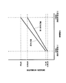
図13は、本発明の実施の形態5に係る燃料電池システムにおける発電電力と原料流量の関係及び発電電力と第1原料流量の関係を示すグラフである。
FIG. 13 is a graph showing the relationship between the generated power and the raw material flow rate and the relationship between the generated power and the first raw material flow rate in the fuel cell system according to
制御器22は、図13に示すように、燃料電池2の発電量に応じて予め設定された供給能力になるように原料供給器4を制御しているとする。すなわち、本実施の形態5においては、制御器22は、燃料電池装置24の最低発電電力である200Wで発電する場合に、燃料電池装置24(正確には、水素生成器3)に供給される原料の流量が1NLMとなるように、原料供給器4の供給能力を制御している。また、制御器22は、燃料電池装置24の最高発電電力である1000Wで発電する場合に、燃料電池装置24(正確には、水素生成器3)に供給される原料の流量が4NLMとなるように、原料供給器4の供給能力を制御している。そして、制御器22は、発電電力に対して、燃料電池装置24(正確には、水素生成器3)に供給される原料の流量が、一次直線となるように、原料供給器4の供給能力を制御している。
As shown in FIG. 13, it is assumed that the
ところで、上述したように、燃焼排ガス流路8の水タンク6よりも下流側の流路及び第2酸化剤排ガス流路12bの少なくとも一方の流路が閉塞された場合には、水タンク6の第1貯水部17内の圧力が増加する。第1貯水部17内の圧力の増加に伴い、燃焼排ガス流路8等内の圧力が増加するため、原料供給流路25内の圧力も増加する。このため、制御器22が、例えば、原料の流量が1NLMとなるように、原料供給器4の供給能力を制御していても、原料流量計32で検知される原料の流量は、1NLMより小さいものとなる。
By the way, as described above, when at least one of the flow path downstream of the
そこで、本実施の形態5に係る燃料電池システム1では、制御器22が、燃料電池2の発電量に応じて予め設定された供給能力になるように原料供給器4を制御している場合に、原料流量計32が予め設定された第1原料流量より低い流量を検知した場合には、燃料電池装置24(燃料電池システム1)の運転を停止するように構成されている。ここで、第1原料流量は、燃料電池システム1の構成等により、予め設定されたものである。
Therefore, in the
具体的には、例えば、図13に示すように、第1原料流量は、燃料利用率の増加に伴う燃料電池2の劣化を抑制するために、以下のように設定されている。すなわち、第1原料流量は、燃料電池装置24の最低発電電力である200Wで発電する場合には、燃料利用率が90%となる0.8NLMと設定されている。また、第1原料流量は、燃料電池装置24の最高発電電力である1000Wで発電する場合には、燃料利用率が90%となる3.2NLMと設定されている。そして、第1原料流量は、発電電力に対して、一次直線となるように設定されている。
Specifically, for example, as shown in FIG. 13, the first raw material flow rate is set as follows in order to suppress deterioration of the
制御器22は、例えば、燃料電池装置24を200Wで発電するように制御している場合に、原料流量計32が検知する原料流量が、第1原料流量である0.8NLMより低い流量を検知した場合に、燃焼排ガス流路8の水タンク6よりも下流側の流路及び第2酸化剤排ガス流路12bの少なくとも一方の流路が閉塞されていると判断し、燃料電池装置24の運転を停止する。このため、燃料電池2や水素生成器3が破損されることを抑制することができる。
For example, when the
このように構成された本実施の形態5に係る燃料電池システム1であっても、実施の形態1に係る燃料電池システム1と同様の作用効果を奏する。また、本実施の形態5に係る燃料電池システム1では、原料流量計32で検知される原料の流量が第1原料流量より低い流量を検知すると、燃料電池装置24(燃料電池システム1)の運転を停止するため、燃料電池2や水素生成器3の破損をより抑制することができる。
Even the
(実施の形態6)
本発明の実施の形態6に係る燃料電池システムは、制御器と、燃料電池装置に酸化剤ガスを供給する酸化剤ガス供給器と、を備え、燃料電池装置は、燃料電池を有し、燃料電池には、アノードに燃料ガスを供給する燃料ガス内部流路とカソードに酸化剤ガスを供給する酸化剤ガス内部流路が設けられ、酸化剤ガス内部流路の下流端に、排ガス流路が接続されており、制御器は、燃料電池の発電量に応じた規定流量の酸化剤ガスを供給するように酸化剤ガス供給器をフィードバック制御しており、酸化剤ガス供給器の供給能力が予め設定された第2供給能力よりも高くなる場合には、燃料電池装置の運転を停止するように構成されている態様を例示するものである。
(Embodiment 6)
A fuel cell system according to
ここで、「第2供給能力」は、水素生成器の耐圧及び燃料電池の耐圧のうち、小さい方の圧力よりも小さい圧力となる酸化剤ガス供給器の供給能力をいう。 Here, the “second supply capacity” refers to the supply capacity of the oxidant gas supplier that has a pressure smaller than the smaller one of the pressure resistance of the hydrogen generator and the pressure resistance of the fuel cell.
[燃料電池システムの構成]
図14は、本発明の実施の形態6に係る燃料電池システムの概略構成を示す模式図である。
[Configuration of fuel cell system]
FIG. 14 is a schematic diagram showing a schematic configuration of a fuel cell system according to
図14に示すように、本発明の実施の形態46係る燃料電池システム1は、実施の形態1に係る燃料電池システム1と基本的構成は同じであるが、制御器22が設けられている点が異なる。また、本実施の形態6に係る燃料電池システム1では、排ガス流路として、酸化剤排ガス流路12を規定している点が、実施の形態1に係る燃料電池システム1と異なる。なお、制御器22は、実施の形態2で説明した制御器22と同様に構成されているため、その詳細な説明は省略する。
As shown in FIG. 14, the
[燃料電池システムの作用効果]
次に、本実施の形態6に係る燃料電池システム1の作用効果について説明する。
[Function and effect of fuel cell system]
Next, functions and effects of the
上述したように、燃焼排ガス流路8の水タンク6よりも下流側の流路及び第2酸化剤排ガス流路12bの少なくとも一方の流路が閉塞された場合には、水タンク6の第1貯水部17内の圧力が増加する。第1貯水部17内の圧力の増加に伴い、燃焼排ガス流路8等内の圧力が増加するため、酸化剤ガス供給流路28内の圧力も増加する。
As described above, when at least one of the flow path downstream from the
ここで、制御器22が、燃料電池2の発電量に応じた規定流量の酸化剤ガスを供給するように酸化剤ガス供給器10をフィードバック制御しているとする。燃料電池2の発電量が一定である場合であっても、酸化剤ガス供給流路28内の圧力が増加すると、酸化剤ガス供給器10の供給能力が一定であると、燃料電池2の発電量に応じた規定流量の酸化剤ガスを供給することができなくなる。
Here, it is assumed that the
このため、制御器22は、その供給能力を増加するように、酸化剤ガス供給器10を制御する。したがって、燃料電池2の発電量によっては、制御器22は、燃料電池2や水素生成器3の耐圧以上の圧力がかかるまで、酸化剤ガス供給器10の供給能力を増加させるおそれがある。
For this reason, the
そこで、本実施の形態6に係る燃料電池システム1では、制御器22が、燃料電池2の発電量に応じた規定流量の酸化剤ガスを供給するように、酸化剤ガス供給器10をフィードバック制御している場合に、酸化剤ガス供給器10の供給能力が予め設定された第2供給能力よりも高くなる場合には、燃料電池装置24(燃料電池システム1)の運転を停止するように構成されている。
Therefore, in the
具体的には、例えば、酸化剤ガス供給器10の供給能力が70%以上では、燃料電池2や水素生成器3の耐圧以上になり、燃料電池2や水素生成器3が破損するおそれがあるとする。このとき、第2供給能力を70%から5ポイント低い65%と規定したとする。制御器22は、酸化剤ガス供給器10の供給能力が65%よりも高くなるように、酸化剤ガス供給器10を制御したとき、燃焼排ガス流路8の水タンク6よりも下流側の流路及び第2酸化剤排ガス流路12bの少なくとも一方の流路が閉塞されていると判断し、燃料電池装置24の運転を停止する。このため、燃料電池2や水素生成器3が破損されることを抑制することができる。
Specifically, for example, when the supply capacity of the oxidant
このように構成された本実施の形態6に係る燃料電池システム1であっても、実施の形態1に係る燃料電池システム1と同様の作用効果を奏する。また、本実施の形態6に係る燃料電池システム1では、酸化剤ガス供給器10の供給能力が予め設定された第2供給能力よりも高くなると、燃料電池装置24(燃料電池システム1)の運転を停止するため、燃料電池2や水素生成器3の破損をより抑制することができる。
Even the
なお、本実施の形態6においては、制御器22が、燃料電池2の発電量に応じた規定流量の酸化剤ガスを供給するように酸化剤ガス供給器10をフィードバック制御しているとしたが、これに限定されない。例えば、制御器22は、酸化剤ガスの流量を測定する酸化剤ガス流量計で酸化剤ガスの流量が規定流量になるようにフィードバック制御してもよい。
In the sixth embodiment, the
(実施の形態7)
本発明の実施の形態7に係る燃料電池システムは、制御器と、燃料電池装置に酸化剤ガスを供給する酸化剤ガス供給器と、酸化剤ガス供給器から燃料電池装置に供給される酸化剤ガスの流量を検知する酸化剤ガス流量検知器と、を備え、燃料電池装置は、燃料電池を有し、燃料電池には、アノードに燃料ガスを供給する燃料ガス内部流路とカソードに酸化剤ガスを供給する酸化剤ガス内部流路が設けられ、酸化剤ガス内部流路の下流端に、排ガス流路が接続されており、制御器は、燃料電池の発電量に応じて予め設定された供給能力になるように酸化剤ガス供給器を制御しており、酸化剤ガス流量検知器が予め設定された第1酸化剤ガス流量より低い流量を検知した場合には、燃料電池装置の運転を停止するように構成されている態様を例示するものである。
(Embodiment 7)
A fuel cell system according to
[燃料電池システムの構成]
図15は、本発明の実施の形態7に係る燃料電池システムの概略構成を示す模式図である。
[Configuration of fuel cell system]
FIG. 15 is a schematic diagram showing a schematic configuration of a fuel cell system according to
図15に示すように、本発明の実施の形態7に係る燃料電池システム1は、実施の形態1に係る燃料電池システム1と基本的構成は同じであるが、制御器22と空気流量計(酸化剤ガス流量検知器)42が設けられている点が異なる。また、本実施の形態7係る燃料電池システム1では、排ガス流路として、酸化剤排ガス流路12を規定している点が、実施の形態1に係る燃料電池システム1と異なる。
As shown in FIG. 15, the
空気流量計42は、酸化剤ガス供給流路28を通流する酸化剤ガスの流量を検知することができれば、どのような形態であってもよい。空気流量計42としては、例えば、ベンチュリ計やオリフィス流量計等を用いることができる。なお、制御器22は、実施の形態2で説明した制御器22と同様に構成されているため、その詳細な説明は省略する。
The air flow meter 42 may have any form as long as it can detect the flow rate of the oxidant gas flowing through the oxidant
[燃料電池システムの作用効果]
次に、本実施の形態7に係る燃料電池システム1の作用効果について説明する。
[Function and effect of fuel cell system]
Next, functions and effects of the
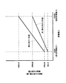
図16は、本発明の実施の形態7に係る燃料電池システムにおける発電電力と酸化剤ガス流量の関係及び発電電力と第1酸化剤ガス流量の関係を示すグラフである。
FIG. 16 is a graph showing the relationship between the generated power and the oxidant gas flow rate and the relationship between the generated power and the first oxidant gas flow rate in the fuel cell system according to
制御器22は、図16に示すように、燃料電池2の発電量に応じて予め設定された供給能力になるように酸化剤ガス供給器10を制御しているとする。すなわち、本実施の形態7においては、制御器22は、燃料電池装置24の最低発電電力である200Wで発電する場合に、燃料電池装置24(正確には、燃料電池2)に供給される酸化剤ガスの流量が10NLMとなるように、酸化剤ガス供給器10の供給能力を制御している。また、制御器22は、燃料電池装置24の最高発電電力である1000Wで発電する場合に、燃料電池装置24(正確には、燃料電池2)に供給される酸化剤ガスの流量が40NLMとなるように、酸化剤ガス供給器10の供給能力を制御している。そして、制御器22は、発電電力に対して、燃料電池装置24(正確には、燃料電池2)に供給される酸化剤ガスの流量が、一次直線となるように、酸化剤ガス供給器10の供給能力を制御している。
As shown in FIG. 16, it is assumed that the
ところで、上述したように、燃焼排ガス流路8の水タンク6よりも下流側の流路及び第2酸化剤排ガス流路12bの少なくとも一方の流路が閉塞された場合には、水タンク6の第1貯水部17内の圧力が増加する。第1貯水部17内の圧力の増加に伴い、燃焼排ガス流路8等内の圧力が増加するため、酸化剤ガス供給流路28内の圧力も増加する。このため、制御器22が、例えば、酸化剤ガスの流量が4NLMとなるように、酸化剤ガス供給器10の供給能力を制御していても、空気流量計42で検知される原料の流量は、4NLMより小さいものとなる。
By the way, as described above, when at least one of the flow path downstream of the
そこで、本実施の形態7に係る燃料電池システム1では、制御器22が、燃料電池2の発電量に応じて予め設定された供給能力になるように酸化剤ガス供給器10を制御している場合に、42が予め設定された第1酸化剤ガス流量より低い流量を検知した場合には、燃料電池装置24(燃料電池システム1)の運転を停止するように構成されている。ここで、第1酸化剤ガス流量は、燃料電池システム1の構成等により、予め設定されたものである。
Therefore, in the
具体的には、例えば、図16に示すように、第1酸化剤ガス流量は、酸化剤利用率の増加に伴う燃料電池2の劣化を抑制するために、以下のように設定されている。すなわち、第1酸化剤ガス流量は、燃料電池装置24の最低発電電力である200Wで発電する場合には、酸化剤利用率が80%となる6NLMと設定されている。また、第1酸化剤ガス流量は、燃料電池装置24の最高発電電力である1000Wで発電する場合には、酸化剤利用率が80%となる24NLMと設定されている。そして、第1酸化剤ガス流量は、発電電力に対して、一次直線となるように設定されている。
Specifically, for example, as shown in FIG. 16, the first oxidant gas flow rate is set as follows in order to suppress deterioration of the
制御器22は、例えば、燃料電池装置24を200Wで発電するように制御している場合に、空気流量計42が検知する酸化剤ガス流量が、第1酸化剤ガス流量である6NLMより低い流量を検知した場合に、燃焼排ガス流路8の水タンク6よりも下流側の流路及び第2酸化剤排ガス流路12bの少なくとも一方の流路が閉塞されていると判断し、燃料電池装置24の運転を停止する。このため、燃料電池2や水素生成器3が破損されることを抑制することができる。
For example, when the
このように構成された本実施の形態7に係る燃料電池システム1であっても、実施の形態1に係る燃料電池システム1と同様の作用効果を奏する。また、本実施の形態7に係る燃料電池システム1では、空気流量計42で検知される酸化剤ガスの流量が第1酸化剤ガス流量より低い流量を検知すると、燃料電池装置24(燃料電池システム1)の運転を停止するため、燃料電池2や水素生成器3の破損をより抑制することができる。
Even the
(実施の形態8)
[燃料電池システムの構成]
図17は、本発明の実施の形態8に係る燃料電池システムの概略構成を示す模式図である。
(Embodiment 8)
[Configuration of fuel cell system]
FIG. 17 is a schematic diagram showing a schematic configuration of a fuel cell system according to
図17に示すように、本発明の実施の形態8に係る燃料電池システム1は、実施の形態1に係る燃料電池システム1と基本的構成は同じであるが、排ガス流路が第1燃焼排ガス流路8aと第2燃焼排ガス流路8bで構成されている点と、排気口7が燃焼排ガスを排出する第1排気口7aと酸化剤排ガスを排出する第2排気口7bで構成されている点が異なる。
As shown in FIG. 17, the
また、本実施の形態8に係る燃料電池システム1では、酸化剤排ガス流路12を通流する酸化剤排ガス内の水分を水タンク6に貯えられず、第2排気口7bから排出されるように構成されている。
Further, in the
このように構成された本実施の形態8に係る燃料電池システム1では、第1燃焼排ガス流路8a及び第1排気口7aのいずれかが閉塞したような場合であっても、第1貯水部17の水位が隔壁16より低くなると、第1貯水部17内のガス(燃焼排ガスを含む)は、第2貯水部18から排水口20を介して、燃料電池システム1外(大気中)に排出される。
In the
このため、本実施の形態8に係る燃料電池システム1では、第1燃焼排ガス流路8a及び第1排気口7aのいずれかが閉塞されても、第1貯水部17内の圧力が、燃料電池2の耐圧、水素生成器3の耐圧、原料供給器4の締結圧、及び酸化剤ガス供給器10の締結圧のうち、最も小さい圧力以上になることが抑制されるため、燃料電池2、水素生成器3、原料供給器4、及び酸化剤ガス供給器10の破損を抑制することができる。
For this reason, in the
上記説明から、当業者にとっては、本発明の多くの改良や他の実施形態が明らかである。したがって、上記説明は、例示としてのみ解釈されるべきであり、本発明を実行する最良の態様を当業者に教示する目的で提供されたものである。本発明の要旨を逸脱することなく、その構造及び/又は機能の詳細を実質的に変更できる。また、上記実施形態に開示されている複数の構成要素の適宜な組合せにより種々の発明を形成できる。 From the foregoing description, many modifications and other embodiments of the present invention are obvious to one skilled in the art. Accordingly, the foregoing description should be construed as illustrative only and is provided for the purpose of teaching those skilled in the art the best mode of carrying out the invention. The details of the structure and / or function may be substantially changed without departing from the scope of the invention. Moreover, various inventions can be formed by appropriately combining a plurality of constituent elements disclosed in the embodiment.
本発明の燃料電池システム及びその運転方法は、水素生成器や燃料電池の破損を抑制することができるため、燃料電池の分野で有用である。 The fuel cell system and the operation method thereof according to the present invention are useful in the field of fuel cells because they can suppress damage to the hydrogen generator and the fuel cell.
1 燃料電池システム
2 燃料電池
2a 燃料ガス内部流路
2b 酸化剤ガス内部流路
3 水素生成器
3a 燃焼器
4 原料供給器
5 燃焼排ガス熱交換器
6 水タンク
7 排気口
7a 第1排気口
7b 第2排気口
8 燃焼排ガス流路
8a 第1燃焼排ガス流路
8b 第2燃焼排ガス流路
9 燃焼排ガス凝縮水流路
10 酸化剤ガス供給器
11 酸化剤排ガス熱交換器
12 酸化剤排ガス流路
12a 第1酸化剤排ガス流路
12b 第2酸化剤排ガス流路
13 酸化剤排ガス凝縮水流路
14 貯湯タンク
15 温水循環経路
16 隔壁
17 第1貯水部
18 第2貯水部
19 水位検知器
20 排水口
21 給水弁
22 制御器
23 筐体
24 燃料電池装置
25 原料供給流路
26 燃料ガス供給流路
27 オフ燃料ガス流路
28 酸化剤ガス供給流路
29 連通部
30 水供給流路
31 排水流路
32 原料流量計
42 空気流量計
60 セル積層体
61 セル
62 端板
63 端板
64 燃料ガス供給マニホールド
65 燃料ガス排出マニホールド
66 酸化剤ガス供給マニホールド
67 酸化剤ガス排出マニホールド
71 高分子電解質膜
72A アノード
72B カソード
73 MEA(Membrane−Electrode−Assembly:膜−電極接合体)
74 ガスケット
75A アノードセパレータ
75B カソードセパレータ
77 燃料ガス流路
78 酸化剤ガス流路
201 燃料電池発電装置
202 燃料電池本体
203 改質装置
203a バーナー
204 反応空気ブロワ
205 燃料予熱器
206 排熱回収器
207 排気塔
207a 排気口
208 フィルター
209 回収水タンク
210 生成水回収装置
DESCRIPTION OF SYMBOLS 1 Fuel cell system 2 Fuel cell 2a Fuel gas internal flow path 2b Oxidant gas internal flow path 3 Hydrogen generator 3a Combustor 4 Raw material supply device 5 Combustion exhaust gas heat exchanger 6 Water tank 7 Exhaust port 7a First exhaust port 7b First 2 exhaust port 8 combustion exhaust gas channel 8a first combustion exhaust gas channel 8b second combustion exhaust gas channel 9 combustion exhaust gas condensate water channel 10 oxidant gas supply device 11 oxidant exhaust gas heat exchanger 12 oxidant exhaust gas channel 12a first Oxidant exhaust gas flow path 12b Second oxidant exhaust gas flow path 13 Oxidant exhaust gas condensed water flow path 14 Hot water storage tank 15 Hot water circulation path 16 Bulkhead 17 First water storage part 18 Second water storage part 19 Water level detector 20 Drain port 21 Water supply valve 22 Controller 23 Case 24 Fuel cell device 25 Raw material supply flow path 26 Fuel gas supply flow path 27 Off-fuel gas flow path 28 Oxidant gas supply flow path 29 Communication portion 30 Water supply flow path 31 Drainage flow path 32 Raw material flow meter 42 Air flow meter 60 Cell stack 61 Cell 62 End plate 63 End plate 64 Fuel gas supply manifold 65 Fuel gas discharge manifold 66 Oxidant gas supply manifold 67 Oxidant gas discharge Manifold 71 Polymer electrolyte membrane 72A Anode 72B Cathode 73 MEA (Membrane-Electrode-Assembly: membrane-electrode assembly)
74
Claims (16)
前記水タンクは、第1貯水部と、第2貯水部と、該水タンクの下部で前記第1貯水部と前記第2貯水部とを連通するように構成された連通部と、を有し、
前記水タンクの第2貯水部には、前記連通部より上方に排水口が設けられ、
前記排ガス流路は、前記水タンクの前記第1貯水部に接続され、
前記排ガス流路の前記水タンクよりも下流側が閉塞されていない場合には、前記排ガスは前記排ガス流路から大気中に排出され、
前記排ガス流路の前記水タンクよりも下流側が閉塞されている場合には、前記排ガスは前記水タンクの前記排水口を介して大気中に排出されるように構成されている、燃料電池システム。A fuel cell device in which power is generated by supplying raw material and an oxidant gas containing oxygen, an exhaust gas passage for exhausting exhaust gas exhausted from the fuel cell device to the atmosphere, and storing water in the exhaust gas a water tank configured, a fuel cell system including the in the,
The water tank includes a first water storage section, a second water storage section, and a communication section configured to communicate the first water storage section and the second water storage section at a lower portion of the water tank. ,
The second water storage portion before Symbol water tank, drain outlet is provided above said communicating portion,
The exhaust gas flow path is connected to the first water reservoir of the water tank;
If unobstructed downstream side of the water tank before Symbol exhaust gas flow path, the exhaust gas is discharged into the atmosphere from the exhaust gas passage,
When than the water tank before Symbol exhaust passage downstream is closed, the exhaust gas is configured to be discharged to the atmosphere through the drain outlet of the water tank, fuel Battery system.
前記第2流路が閉塞されている場合には、前記排ガスは前記水タンクの前記排水口を介して大気中に排出されるように構成されている、請求項1に記載の燃料電池システム。The exhaust gas flow path has one end connected to the fuel cell device, the other end connected to the first water reservoir of the water tank, and one end connected to the first water reservoir of the water tank. A second flow path whose other end is open to the atmosphere,
2. The fuel cell system according to claim 1, wherein when the second flow path is closed , the exhaust gas is configured to be discharged into the atmosphere through the drain port of the water tank.
前記第4流路が閉塞されている場合には、前記排ガスは前記水タンクの前記排水口を介して大気中に排出されるように構成されている、請求項1に記載の燃料電池システム。The exhaust gas flow path has one end connected to the fuel cell device, the other end connected to the first water reservoir of the water tank, and one end connected to the middle of the third flow path. A fourth flow path whose other end is open to the atmosphere,
2. The fuel cell system according to claim 1, wherein, when the fourth flow path is closed , the exhaust gas is configured to be discharged into the atmosphere through the drain port of the water tank.
前記水タンクの前記第1貯水部に設けられ、該第1貯水部の水位を検知する水位検知器と、をさらに備え、 A water level detector provided in the first water reservoir of the water tank for detecting the water level of the first water reservoir,
前記制御器は、前記排ガスが前記水タンクの前記排水口を介して大気中に排出される場合の水位である第1水位を前記水位検知器が検知した場合に、前記燃料電池装置の運転を停止するように構成されている、請求項1〜4のいずれか1項に記載の燃料電池システム。 The controller controls the operation of the fuel cell device when the water level detector detects a first water level which is a water level when the exhaust gas is discharged into the atmosphere through the drain port of the water tank. The fuel cell system according to claim 1, wherein the fuel cell system is configured to be stopped.
前記水タンクの前記第1貯水部に設けられ、該第1貯水部の水位を検知する水位検知器と、
前記水タンクの前記第1貯水部に水を供給するように構成された水供給器と、をさらに備え、
前記制御器は、前記排ガスが前記水タンクの前記排水口を介して大気中に排出される場合の水位である第1水位よりも高く、かつ、前記第1貯水部の満水位よりも低い水位である第2水位を前記水位検知器が検知した場合に、前記水タンクの第1貯水部に水を供給するように水供給器を制御し、
前記水供給器が前記第1貯水部に水を供給してから所定時間経過後に、前記水位検知器が前記第1水位を検知した場合に、前記燃料電池装置の運転を停止するように構成されている、請求項1〜4のいずれか1項に記載の燃料電池システム。 A controller;
A water level detector provided in the first water reservoir of the water tank for detecting the water level of the first water reservoir;
A water supplier configured to supply water to the first water reservoir of the water tank,
The controller has a water level that is higher than a first water level that is a water level when the exhaust gas is discharged into the atmosphere through the drain port of the water tank and lower than a full water level of the first water storage section. When the water level detector detects the second water level, the water supply is controlled to supply water to the first water storage part of the water tank,
The fuel cell device is configured to stop operation when the water level detector detects the first water level after a predetermined time has elapsed since the water supply unit supplied water to the first water reservoir. The fuel cell system according to any one of claims 1 to 4.
前記燃料電池には、アノードに燃料ガスを供給する燃料ガス内部流路とカソードに前記酸化剤ガスを供給する酸化剤ガス内部流路が設けられ、
前記排ガス流路は、前記燃料ガス内部流路の下流端にその上流端が接続された燃料ガス排ガス流路と、前記酸化剤ガス内部流路の下流端にその下流端が接続された酸化剤ガス排ガス流路と、を有している、請求項1〜7のいずれか1項に記載の燃料電池システム。The fuel cell device includes a fuel cell,
The fuel cell is provided with a fuel gas internal flow path for supplying fuel gas to the anode and an oxidant gas internal flow path for supplying the oxidant gas to the cathode,
The exhaust gas flow path includes a fuel gas exhaust gas flow path whose upstream end is connected to the downstream end of the fuel gas internal flow path, and an oxidant whose downstream end is connected to the downstream end of the oxidant gas internal flow path The fuel cell system according to any one of claims 1 to 7 , comprising a gas exhaust gas flow path.
前記燃料電池装置に前記原料を供給する原料供給器と、
前記原料供給器から前記燃料電池装置に供給される前記原料の流量を検知する原料流量検知器と、を備え、
前記燃料電池装置は、燃料電池を有し、
前記燃料電池には、アノードに燃料ガスを供給する燃料ガス内部流路とカソードに前記酸化剤ガスを供給する酸化剤ガス内部流路が設けられ、
前記燃料ガス内部流路の下流端に、前記排ガス流路が接続されており、
前記制御器は、前記燃料電池の発電量に応じて予め設定された供給能力になるように前記原料供給器を制御しており、
前記原料流量検知器が予め設定された第1原料流量より低い流量を検知した場合には、前記燃料電池装置の運転を停止するように構成されている、請求項1〜8のいずれか1項に記載の燃料電池システム。 A controller;
A raw material supplier for supplying the raw material to the fuel cell device;
A raw material flow rate detector for detecting the flow rate of the raw material supplied from the raw material supply device to the fuel cell device,
The fuel cell device includes a fuel cell,
The fuel cell is provided with a fuel gas internal flow path for supplying fuel gas to the anode and an oxidant gas internal flow path for supplying the oxidant gas to the cathode,
The exhaust gas flow path is connected to the downstream end of the fuel gas internal flow path,
The controller controls the raw material supplier to have a preset supply capacity according to the power generation amount of the fuel cell,
When detecting the flow rate lower than the first material flow the raw material flow rate detector is set in advance, the fuel cell system is configured to stop the operation of any one of claims 1-8 The fuel cell system described in 1.
前記燃料電池装置に前記原料を供給する原料供給器と、を備え、
前記燃料電池装置は、燃料電池を有し、
前記燃料電池には、アノードに燃料ガスを供給する燃料ガス内部流路とカソードに前記酸化剤ガスを供給する酸化剤ガス内部流路が設けられ、
前記燃料ガス内部流路の下流端に、前記排ガス流路が接続されており、
前記制御器は、前記燃料電池の発電量に応じた規定流量の前記原料を供給するように前記原料供給器をフィードバック制御しており、
前記原料供給器の供給能力が予め設定された第1供給能力よりも高くなる場合には、前記排ガス流路の前記水タンクよりも下流側が閉塞されていると判断し、前記燃料電池装置の運転を停止するように構成されている、請求項1〜8のいずれか1項に記載の燃料電池システム。 A controller;
A raw material supplier for supplying the raw material to the fuel cell device,
The fuel cell device includes a fuel cell,
The fuel cell is provided with a fuel gas internal flow path for supplying fuel gas to the anode and an oxidant gas internal flow path for supplying the oxidant gas to the cathode,
The exhaust gas flow path is connected to the downstream end of the fuel gas internal flow path,
The controller feedback-controls the raw material supplier so as to supply the raw material at a specified flow rate according to the power generation amount of the fuel cell,
When the supply capacity of the raw material supplier becomes higher than a preset first supply capacity, it is determined that the downstream side of the water tank of the exhaust gas passage is closed, and the operation of the fuel cell device is performed. the is configured to stop the fuel cell system according to any one of claims 1-8.
前記燃料電池装置に前記酸化剤ガスを供給する酸化剤ガス供給器と、
前記酸化剤ガス供給器から前記燃料電池装置に供給される前記酸化剤ガスの流量を検知する酸化剤ガス流量検知器と、を備え、
前記燃料電池装置は、燃料電池を有し、
前記燃料電池には、アノードに燃料ガスを供給する燃料ガス内部流路とカソードに前記酸化剤ガスを供給する酸化剤ガス内部流路が設けられ、
前記酸化剤ガス内部流路の下流端に、前記排ガス流路が接続されており、
前記制御器は、前記燃料電池の発電量に応じて予め設定された供給能力になるように前記酸化剤ガス供給器を制御しており、
前記酸化剤ガス流量検知器が予め設定された第1酸化剤ガス流量より低い流量を検知した場合には、前記燃料電池装置の運転を停止するように構成されている、請求項1〜10のいずれか1項に記載の燃料電池システム。 A controller;
An oxidant gas supplier for supplying the oxidant gas to the fuel cell device;
An oxidant gas flow rate detector for detecting a flow rate of the oxidant gas supplied from the oxidant gas supply unit to the fuel cell device;
The fuel cell device includes a fuel cell,
The fuel cell is provided with a fuel gas internal flow path for supplying fuel gas to the anode and an oxidant gas internal flow path for supplying the oxidant gas to the cathode,
The exhaust gas flow path is connected to the downstream end of the oxidant gas internal flow path,
The controller controls the oxidant gas supply device so as to have a preset supply capacity according to the power generation amount of the fuel cell,
When said oxidant gas flow rate detector detects the flow rate lower than the first oxidant gas flow rate which is set in advance, the operation of the fuel cell system is configured to stop, according to claim 1-10 The fuel cell system according to any one of claims.
前記燃料電池装置に前記酸化剤ガスを供給する酸化剤ガス供給器と、を備え、
前記燃料電池装置は、燃料電池を有し、
前記燃料電池には、アノードに燃料ガスを供給する燃料ガス内部流路とカソードに前記酸化剤ガスを供給する酸化剤ガス内部流路が設けられ、
前記酸化剤ガス内部流路の下流端に、前記排ガス流路が接続されており、
前記制御器は、前記燃料電池の発電量に応じた規定流量の前記酸化剤ガスを供給するように前記酸化剤ガス供給器をフィードバック制御しており、
前記酸化剤ガス供給器の供給能力が予め設定された第2供給能力よりも高くなる場合には、前記排ガスの通流が前記排ガス流路の前記水タンクよりも下流側で閉塞されていると判断し、前記燃料電池装置の運転を停止するように構成されている、請求項1〜10のいずれか1項に記載の燃料電池システム。 A controller;
An oxidant gas supplier for supplying the oxidant gas to the fuel cell device,
The fuel cell device includes a fuel cell,
The fuel cell is provided with a fuel gas internal flow path for supplying fuel gas to the anode and an oxidant gas internal flow path for supplying the oxidant gas to the cathode,
The exhaust gas flow path is connected to the downstream end of the oxidant gas internal flow path,
The controller feedback-controls the oxidant gas supply so as to supply the oxidant gas at a specified flow rate according to the power generation amount of the fuel cell,
When the supply capacity of the oxidant gas supply device is higher than a preset second supply capacity, the flow of the exhaust gas is blocked downstream of the water tank of the exhaust gas passage. The fuel cell system according to any one of claims 1 to 10 , wherein the fuel cell system is configured to determine and stop the operation of the fuel cell device.
前記連通部の上端から前記排水口の下端までの高さに対応する水圧差が前記燃料電池の耐圧より低くなるように、前記連通部及び前記排水口が前記水タンクに設けられている、請求項1〜12のいずれか1項に記載の燃料電池システム。The fuel cell device includes a fuel cell,
The communication portion and the drain port are provided in the water tank so that a water pressure difference corresponding to a height from an upper end of the communication portion to a lower end of the drain port is lower than a pressure resistance of the fuel cell. Item 13. The fuel cell system according to any one of Items 1 to 12 .
前記連通部の上端から前記排水口の下端までの高さに対応する水圧差が前記水素生成器の耐圧より低くなるように、前記連通部及び前記排水口が前記水タンクに設けられている、請求項1〜13のいずれか1項に記載の燃料電池システム。The fuel cell device includes a hydrogen generator that reforms the raw material to generate fuel gas,
The communication portion and the drain port are provided in the water tank so that the water pressure difference corresponding to the height from the upper end of the communication portion to the lower end of the drain port is lower than the pressure resistance of the hydrogen generator. The fuel cell system according to any one of claims 1 to 13 .
前記燃料電池装置に前記酸化剤ガスを供給する酸化剤ガス供給器と、を備え、
前記連通部の上端から前記排水口の下端までの高さに対応する水圧差が前記原料供給器及び前記酸化剤ガス供給器の少なくとも一方の供給器の締切圧より低くなるように、前記連通部及び前記排水口が前記水タンクに設けられている、請求項1〜14のいずれか1項に記載の燃料電池システム。A raw material supplier for supplying the raw material to the fuel cell device;
An oxidant gas supplier for supplying the oxidant gas to the fuel cell device,
The communication portion is configured such that a water pressure difference corresponding to a height from an upper end of the communication portion to a lower end of the drain port is lower than a cutoff pressure of at least one of the raw material supply device and the oxidant gas supply device. and said drain port is provided in the water tank, the fuel cell system according to any one of claims 1-14.
前記燃料電池システムは、前記水タンクの前記第1貯水部に設けられ、該第1貯水部の水位を検知する水位検知器と、をさらに備え、
前記水タンクは、第1貯水部と、第2貯水部と、該水タンクの下部で前記第1貯水部と前記第2貯水部とを連通するように構成された連通部と、を有し、
前記水タンクの第2貯水部には、前記連通部より上方に排水口が設けられ、
前記排ガス流路は、前記水タンクの前記第1貯水部に接続され、
前記排ガス流路の前記水タンクよりも下流側が閉塞されていない場合には、前記排ガスは前記排ガス流路から大気中に排出され、
前記排ガス流路の前記水タンクよりも下流側が閉塞されている場合には、前記排ガスは前記水タンクの前記排水口を介して大気中に排出されるように構成され、
前記排ガスが前記水タンクの前記排水口を介して大気中に排出される場合の水位である第1水位を前記水位検知器が検知した場合に、前記燃料電池装置の運転を停止する、燃料電池システムの運転方法。A fuel cell device in which power is generated by supplying raw material and an oxidant gas containing oxygen, an exhaust gas passage for exhausting exhaust gas exhausted from the fuel cell device to the atmosphere, and storing water in the exhaust gas A fuel tank system comprising: a water tank configured to:
The fuel cell system further includes a water level detector provided in the first water storage part of the water tank and detecting the water level of the first water storage part,
The water tank includes a first water storage section, a second water storage section, and a communication section configured to communicate the first water storage section and the second water storage section at a lower portion of the water tank. ,
The second water storage part of the water tank is provided with a drain outlet above the communication part,
The exhaust gas flow path is connected to the first water reservoir of the water tank;
If unobstructed downstream side of the water tank before Symbol exhaust gas flow path, the exhaust gas is discharged into the atmosphere from the exhaust gas passage,
When than the water tank before Symbol exhaust passage downstream is closed, the exhaust gas is configured to be discharged to the atmosphere through the drain outlet of the water tank,
A fuel cell that stops operation of the fuel cell device when the water level detector detects a first water level that is a water level when the exhaust gas is discharged into the atmosphere through the drain port of the water tank. How to operate the system.
Priority Applications (1)
| Application Number | Priority Date | Filing Date | Title |
|---|---|---|---|
| JP2011526167A JP5048870B2 (en) | 2010-01-27 | 2011-01-26 | Fuel cell system and operation method thereof |
Applications Claiming Priority (4)
| Application Number | Priority Date | Filing Date | Title |
|---|---|---|---|
| JP2010014953 | 2010-01-27 | ||
| JP2010014953 | 2010-01-27 | ||
| JP2011526167A JP5048870B2 (en) | 2010-01-27 | 2011-01-26 | Fuel cell system and operation method thereof |
| PCT/JP2011/000407 WO2011093066A1 (en) | 2010-01-27 | 2011-01-26 | Fuel cell system and operation method therefor |
Publications (2)
| Publication Number | Publication Date |
|---|---|
| JP5048870B2 true JP5048870B2 (en) | 2012-10-17 |
| JPWO2011093066A1 JPWO2011093066A1 (en) | 2013-05-30 |
Family
ID=44319062
Family Applications (1)
| Application Number | Title | Priority Date | Filing Date |
|---|---|---|---|
| JP2011526167A Expired - Fee Related JP5048870B2 (en) | 2010-01-27 | 2011-01-26 | Fuel cell system and operation method thereof |
Country Status (4)
| Country | Link |
|---|---|
| US (1) | US20120077097A1 (en) |
| EP (1) | EP2530774B1 (en) |
| JP (1) | JP5048870B2 (en) |
| WO (1) | WO2011093066A1 (en) |
Families Citing this family (7)
| Publication number | Priority date | Publication date | Assignee | Title |
|---|---|---|---|---|
| JP6057222B2 (en) * | 2012-05-08 | 2017-01-11 | パナソニックIpマネジメント株式会社 | Power generation system |
| JP6650592B2 (en) * | 2016-10-28 | 2020-02-19 | パナソニックIpマネジメント株式会社 | Fuel cell system |
| CN108791030B (en) * | 2018-07-23 | 2023-10-20 | 成都客车股份有限公司 | Road surface dust suppression system for hydrogen fuel cell automobile and hydrogen fuel cell automobile |
| JP2020017507A (en) * | 2018-07-27 | 2020-01-30 | 京セラ株式会社 | Fuel cell device, control device, and control program |
| JP7664810B2 (en) * | 2021-11-01 | 2025-04-18 | 大阪瓦斯株式会社 | Abnormality diagnosis device |
| JP7720271B2 (en) * | 2022-03-03 | 2025-08-07 | 東京瓦斯株式会社 | fuel cell system |
| US12531254B2 (en) * | 2022-12-13 | 2026-01-20 | Hamilton Sundstrand Corporation | Emergency power fuel cell with evaporative cooling |
Citations (11)
| Publication number | Priority date | Publication date | Assignee | Title |
|---|---|---|---|---|
| JPS58114449U (en) * | 1982-01-28 | 1983-08-04 | 三菱重工業株式会社 | Safety device |
| JPH0357163A (en) * | 1989-07-26 | 1991-03-12 | Fuji Electric Co Ltd | Produced water recovery system of fuel cell |
| JPH07320766A (en) * | 1994-05-26 | 1995-12-08 | Toshiba Corp | Fuel cell water recovery system |
| JPH0831443A (en) * | 1994-07-19 | 1996-02-02 | Fuji Electric Co Ltd | Water recovery device for fuel cell power generator |
| JP2003247651A (en) * | 2002-02-27 | 2003-09-05 | Osaka Gas Co Ltd | Liquid seal type safety instrument |
| JP2006300446A (en) * | 2005-04-22 | 2006-11-02 | Matsushita Electric Ind Co Ltd | Air conditioner |
| JP2007257953A (en) * | 2006-03-22 | 2007-10-04 | Matsushita Electric Ind Co Ltd | Fuel cell system |
| JP2008171806A (en) * | 2006-12-11 | 2008-07-24 | Fuji Electric Holdings Co Ltd | Fuel cell power generator |
| JP2008251447A (en) * | 2007-03-30 | 2008-10-16 | Ihi Corp | Drain treatment device of fuel cell power generation device |
| JP2009009886A (en) * | 2007-06-29 | 2009-01-15 | Honda Motor Co Ltd | Fuel cell |
| JP2010250949A (en) * | 2009-04-10 | 2010-11-04 | Panasonic Corp | Fuel cell system |
Family Cites Families (2)
| Publication number | Priority date | Publication date | Assignee | Title |
|---|---|---|---|---|
| JP2005093374A (en) * | 2003-09-19 | 2005-04-07 | Nissan Motor Co Ltd | Fuel cell power generation system and method for stopping fuel cell power generation system |
| US20080220304A1 (en) * | 2007-03-08 | 2008-09-11 | Proton Energy Systems, Inc. | Venting apparatus and system |
-
2011
- 2011-01-26 JP JP2011526167A patent/JP5048870B2/en not_active Expired - Fee Related
- 2011-01-26 US US13/376,538 patent/US20120077097A1/en not_active Abandoned
- 2011-01-26 EP EP11736782.1A patent/EP2530774B1/en not_active Not-in-force
- 2011-01-26 WO PCT/JP2011/000407 patent/WO2011093066A1/en not_active Ceased
Patent Citations (11)
| Publication number | Priority date | Publication date | Assignee | Title |
|---|---|---|---|---|
| JPS58114449U (en) * | 1982-01-28 | 1983-08-04 | 三菱重工業株式会社 | Safety device |
| JPH0357163A (en) * | 1989-07-26 | 1991-03-12 | Fuji Electric Co Ltd | Produced water recovery system of fuel cell |
| JPH07320766A (en) * | 1994-05-26 | 1995-12-08 | Toshiba Corp | Fuel cell water recovery system |
| JPH0831443A (en) * | 1994-07-19 | 1996-02-02 | Fuji Electric Co Ltd | Water recovery device for fuel cell power generator |
| JP2003247651A (en) * | 2002-02-27 | 2003-09-05 | Osaka Gas Co Ltd | Liquid seal type safety instrument |
| JP2006300446A (en) * | 2005-04-22 | 2006-11-02 | Matsushita Electric Ind Co Ltd | Air conditioner |
| JP2007257953A (en) * | 2006-03-22 | 2007-10-04 | Matsushita Electric Ind Co Ltd | Fuel cell system |
| JP2008171806A (en) * | 2006-12-11 | 2008-07-24 | Fuji Electric Holdings Co Ltd | Fuel cell power generator |
| JP2008251447A (en) * | 2007-03-30 | 2008-10-16 | Ihi Corp | Drain treatment device of fuel cell power generation device |
| JP2009009886A (en) * | 2007-06-29 | 2009-01-15 | Honda Motor Co Ltd | Fuel cell |
| JP2010250949A (en) * | 2009-04-10 | 2010-11-04 | Panasonic Corp | Fuel cell system |
Also Published As
| Publication number | Publication date |
|---|---|
| EP2530774B1 (en) | 2016-03-30 |
| JPWO2011093066A1 (en) | 2013-05-30 |
| EP2530774A1 (en) | 2012-12-05 |
| US20120077097A1 (en) | 2012-03-29 |
| EP2530774A4 (en) | 2013-11-13 |
| WO2011093066A1 (en) | 2011-08-04 |
Similar Documents
| Publication | Publication Date | Title |
|---|---|---|
| JP5048870B2 (en) | Fuel cell system and operation method thereof | |
| US20090098425A1 (en) | Fuel cell system | |
| CN113039153A (en) | Hydrogen system | |
| JPWO2012091096A1 (en) | Fuel cell system | |
| JP4599461B2 (en) | Fuel cell system | |
| CN101562254B (en) | Fuel supply device for fuel cell and fuel cell system using the same | |
| JP4846883B2 (en) | POLYMER ELECTROLYTE FUEL CELL, FUEL CELL STACK HAVING THE SAME, FUEL CELL SYSTEM, AND METHOD FOR OPERATING FUEL CELL SYSTEM | |
| JP5396421B2 (en) | Fuel cell system | |
| JP4956946B2 (en) | Fuel cell | |
| CN100379067C (en) | fuel cell system | |
| JP2022073312A (en) | Fuel cell power generation system, and control method for fuel cell power generation system | |
| RU2325011C1 (en) | Fuel elements system | |
| JP2014002883A (en) | Fuel cell system | |
| JP2014191965A (en) | Fuel cell system | |
| KR100560495B1 (en) | Reformer of fuel cell system and fuel cell system employing same | |
| JP6632911B2 (en) | Fuel cell, fuel cell combined power generation system, and method of stopping fuel cell | |
| JP2007128786A (en) | Fuel cell system | |
| KR100788195B1 (en) | Fuel cell system | |
| JP2010186668A (en) | Heat storage device and fuel cell system using it | |
| KR20090036014A (en) | Stack Purification Method of Fuel Cell System | |
| JP4656286B2 (en) | Fuel cell system | |
| KR101387756B1 (en) | System for operation of multi fuel cell having thermoelectric element | |
| JP2012079633A (en) | Fuel cell system and shutdown method thereof | |
| KR101127687B1 (en) | Super heated steam generator for fuel cell | |
| EP2381523A1 (en) | Reforming apparatus for fuel cell system |
Legal Events
| Date | Code | Title | Description |
|---|---|---|---|
| TRDD | Decision of grant or rejection written | ||
| A01 | Written decision to grant a patent or to grant a registration (utility model) |
Free format text: JAPANESE INTERMEDIATE CODE: A01 Effective date: 20120626 |
|
| A01 | Written decision to grant a patent or to grant a registration (utility model) |
Free format text: JAPANESE INTERMEDIATE CODE: A01 |
|
| A61 | First payment of annual fees (during grant procedure) |
Free format text: JAPANESE INTERMEDIATE CODE: A61 Effective date: 20120719 |
|
| FPAY | Renewal fee payment (event date is renewal date of database) |
Free format text: PAYMENT UNTIL: 20150727 Year of fee payment: 3 |
|
| R150 | Certificate of patent or registration of utility model |
Ref document number: 5048870 Country of ref document: JP Free format text: JAPANESE INTERMEDIATE CODE: R150 Free format text: JAPANESE INTERMEDIATE CODE: R150 |
|
| LAPS | Cancellation because of no payment of annual fees |