JP5048663B2 - Robot cleaning device - Google Patents
Robot cleaning device Download PDFInfo
- Publication number
- JP5048663B2 JP5048663B2 JP2008520218A JP2008520218A JP5048663B2 JP 5048663 B2 JP5048663 B2 JP 5048663B2 JP 2008520218 A JP2008520218 A JP 2008520218A JP 2008520218 A JP2008520218 A JP 2008520218A JP 5048663 B2 JP5048663 B2 JP 5048663B2
- Authority
- JP
- Japan
- Prior art keywords
- side wall
- main
- end portion
- rear end
- robot cleaning
- Prior art date
- Legal status (The legal status is an assumption and is not a legal conclusion. Google has not performed a legal analysis and makes no representation as to the accuracy of the status listed.)
- Active
Links
- 238000004140 cleaning Methods 0.000 title claims abstract description 110
- 238000001514 detection method Methods 0.000 claims description 13
- 230000008901 benefit Effects 0.000 description 4
- 239000000428 dust Substances 0.000 description 4
- 239000010813 municipal solid waste Substances 0.000 description 4
- 238000005265 energy consumption Methods 0.000 description 3
- 230000005484 gravity Effects 0.000 description 3
- 238000000034 method Methods 0.000 description 3
- 230000001133 acceleration Effects 0.000 description 1
- 230000004888 barrier function Effects 0.000 description 1
- 230000009194 climbing Effects 0.000 description 1
- 230000014509 gene expression Effects 0.000 description 1
- 230000003287 optical effect Effects 0.000 description 1
- 238000005498 polishing Methods 0.000 description 1
- 230000001141 propulsive effect Effects 0.000 description 1
Images


Classifications
-
- A—HUMAN NECESSITIES
- A47—FURNITURE; DOMESTIC ARTICLES OR APPLIANCES; COFFEE MILLS; SPICE MILLS; SUCTION CLEANERS IN GENERAL
- A47L—DOMESTIC WASHING OR CLEANING; SUCTION CLEANERS IN GENERAL
- A47L9/00—Details or accessories of suction cleaners, e.g. mechanical means for controlling the suction or for effecting pulsating action; Storing devices specially adapted to suction cleaners or parts thereof; Carrying-vehicles specially adapted for suction cleaners
-
- A—HUMAN NECESSITIES
- A47—FURNITURE; DOMESTIC ARTICLES OR APPLIANCES; COFFEE MILLS; SPICE MILLS; SUCTION CLEANERS IN GENERAL
- A47L—DOMESTIC WASHING OR CLEANING; SUCTION CLEANERS IN GENERAL
- A47L11/00—Machines for cleaning floors, carpets, furniture, walls, or wall coverings
- A47L11/40—Parts or details of machines not provided for in groups A47L11/02 - A47L11/38, or not restricted to one of these groups, e.g. handles, arrangements of switches, skirts, buffers, levers
-
- A—HUMAN NECESSITIES
- A47—FURNITURE; DOMESTIC ARTICLES OR APPLIANCES; COFFEE MILLS; SPICE MILLS; SUCTION CLEANERS IN GENERAL
- A47L—DOMESTIC WASHING OR CLEANING; SUCTION CLEANERS IN GENERAL
- A47L9/00—Details or accessories of suction cleaners, e.g. mechanical means for controlling the suction or for effecting pulsating action; Storing devices specially adapted to suction cleaners or parts thereof; Carrying-vehicles specially adapted for suction cleaners
- A47L9/009—Carrying-vehicles; Arrangements of trollies or wheels; Means for avoiding mechanical obstacles
-
- A—HUMAN NECESSITIES
- A47—FURNITURE; DOMESTIC ARTICLES OR APPLIANCES; COFFEE MILLS; SPICE MILLS; SUCTION CLEANERS IN GENERAL
- A47L—DOMESTIC WASHING OR CLEANING; SUCTION CLEANERS IN GENERAL
- A47L9/00—Details or accessories of suction cleaners, e.g. mechanical means for controlling the suction or for effecting pulsating action; Storing devices specially adapted to suction cleaners or parts thereof; Carrying-vehicles specially adapted for suction cleaners
- A47L9/28—Installation of the electric equipment, e.g. adaptation or attachment to the suction cleaner; Controlling suction cleaners by electric means
-
- B—PERFORMING OPERATIONS; TRANSPORTING
- B60—VEHICLES IN GENERAL
- B60K—ARRANGEMENT OR MOUNTING OF PROPULSION UNITS OR OF TRANSMISSIONS IN VEHICLES; ARRANGEMENT OR MOUNTING OF PLURAL DIVERSE PRIME-MOVERS IN VEHICLES; AUXILIARY DRIVES FOR VEHICLES; INSTRUMENTATION OR DASHBOARDS FOR VEHICLES; ARRANGEMENTS IN CONNECTION WITH COOLING, AIR INTAKE, GAS EXHAUST OR FUEL SUPPLY OF PROPULSION UNITS IN VEHICLES
- B60K17/00—Arrangement or mounting of transmissions in vehicles
- B60K17/30—Arrangement or mounting of transmissions in vehicles the ultimate propulsive elements, e.g. ground wheels, being steerable
-
- B—PERFORMING OPERATIONS; TRANSPORTING
- B60—VEHICLES IN GENERAL
- B60K—ARRANGEMENT OR MOUNTING OF PROPULSION UNITS OR OF TRANSMISSIONS IN VEHICLES; ARRANGEMENT OR MOUNTING OF PLURAL DIVERSE PRIME-MOVERS IN VEHICLES; AUXILIARY DRIVES FOR VEHICLES; INSTRUMENTATION OR DASHBOARDS FOR VEHICLES; ARRANGEMENTS IN CONNECTION WITH COOLING, AIR INTAKE, GAS EXHAUST OR FUEL SUPPLY OF PROPULSION UNITS IN VEHICLES
- B60K7/00—Disposition of motor in, or adjacent to, traction wheel
- B60K7/0007—Disposition of motor in, or adjacent to, traction wheel the motor being electric
-
- A—HUMAN NECESSITIES
- A47—FURNITURE; DOMESTIC ARTICLES OR APPLIANCES; COFFEE MILLS; SPICE MILLS; SUCTION CLEANERS IN GENERAL
- A47L—DOMESTIC WASHING OR CLEANING; SUCTION CLEANERS IN GENERAL
- A47L2201/00—Robotic cleaning machines, i.e. with automatic control of the travelling movement or the cleaning operation
- A47L2201/04—Automatic control of the travelling movement; Automatic obstacle detection
-
- B—PERFORMING OPERATIONS; TRANSPORTING
- B60—VEHICLES IN GENERAL
- B60K—ARRANGEMENT OR MOUNTING OF PROPULSION UNITS OR OF TRANSMISSIONS IN VEHICLES; ARRANGEMENT OR MOUNTING OF PLURAL DIVERSE PRIME-MOVERS IN VEHICLES; AUXILIARY DRIVES FOR VEHICLES; INSTRUMENTATION OR DASHBOARDS FOR VEHICLES; ARRANGEMENTS IN CONNECTION WITH COOLING, AIR INTAKE, GAS EXHAUST OR FUEL SUPPLY OF PROPULSION UNITS IN VEHICLES
- B60K7/00—Disposition of motor in, or adjacent to, traction wheel
- B60K2007/0038—Disposition of motor in, or adjacent to, traction wheel the motor moving together with the wheel axle
-
- B—PERFORMING OPERATIONS; TRANSPORTING
- B60—VEHICLES IN GENERAL
- B60K—ARRANGEMENT OR MOUNTING OF PROPULSION UNITS OR OF TRANSMISSIONS IN VEHICLES; ARRANGEMENT OR MOUNTING OF PLURAL DIVERSE PRIME-MOVERS IN VEHICLES; AUXILIARY DRIVES FOR VEHICLES; INSTRUMENTATION OR DASHBOARDS FOR VEHICLES; ARRANGEMENTS IN CONNECTION WITH COOLING, AIR INTAKE, GAS EXHAUST OR FUEL SUPPLY OF PROPULSION UNITS IN VEHICLES
- B60K7/00—Disposition of motor in, or adjacent to, traction wheel
- B60K2007/0092—Disposition of motor in, or adjacent to, traction wheel the motor axle being coaxial to the wheel axle
-
- G—PHYSICS
- G05—CONTROLLING; REGULATING
- G05D—SYSTEMS FOR CONTROLLING OR REGULATING NON-ELECTRIC VARIABLES
- G05D1/00—Control of position, course or altitude of land, water, air, or space vehicles, e.g. automatic pilot
- G05D1/02—Control of position or course in two dimensions
- G05D1/021—Control of position or course in two dimensions specially adapted to land vehicles
- G05D1/0227—Control of position or course in two dimensions specially adapted to land vehicles using mechanical sensing means, e.g. for sensing treated area
Abstract
Description
本発明は、ロボット清掃装置、例えば、ロボット真空掃除機に関する。 The present invention relates to a robot cleaning device, for example, a robot vacuum cleaner.
ロボット真空掃除機のようなロボット清掃装置は、技術水準として公知である。一つのそのようなロボット清掃装置が、米国特許第5、369、347号明細書に開示されている。この公知の装置は、円形ブロックの全体形状を有するハウジングを備えている。装置を駆動するために、装置は、一つの駆動車輪と二つの支持車輪とを備えており、支持車輪が、装置の正反対側に配置されている。装置を操舵するために、駆動車輪が、垂直軸線を回りに旋回される。 Robot cleaning devices such as robot vacuum cleaners are well known in the art. One such robotic cleaning device is disclosed in US Pat. No. 5,369,347. This known device comprises a housing having the general shape of a circular block. In order to drive the device, the device comprises one drive wheel and two support wheels, which are arranged on the opposite side of the device. In order to steer the device, the drive wheels are turned around a vertical axis.
上記の公知の装置が、以下の方法で操作されることが出来る。装置が前方に移動するとき、駆動車輪は、支持車輪と平行な向きにされる。例えば、もし装置が、その装置の左側で障害物に衝突すると、駆動車輪が、左に90°旋回され、それにより、装置は、回転が開始する前に完全に停止させられる。回転は、右に向くようになっており、支持車輪が、円形装置の正反対側に配置されているので、各支持車輪の間の中心軸線回りに回転する。さらに、装置が円形状であるため、障害物は、その装置の回転を妨害しない。装置が90°回転すると、駆動車輪が、左に90°旋回され再び支持車輪と平行になる。装置は、前方へ移動を開始し、わずかな距離移動することが可能とされる。次に、駆動車輪が、左に90°旋廻され、中心軸線回りに左に回転を開始する前に、その装置が、再び停止させられる。装置が、左に90°回転された後で、駆動車輪が、支持車輪と平行になるように旋廻されて戻され、装置はさらに最初の向きに前進する。 The above known apparatus can be operated in the following manner. As the device moves forward, the drive wheels are oriented parallel to the support wheels. For example, if a device collides with an obstacle on the left side of the device, the drive wheel is turned 90 ° to the left, thereby causing the device to be completely stopped before rotation begins. The rotation is directed to the right, and the support wheels are arranged on the opposite side of the circular device, so that they rotate around the central axis between each support wheel. Furthermore, since the device is circular, obstacles do not interfere with the rotation of the device. As the device rotates 90 °, the drive wheels turn 90 ° to the left and are again parallel to the support wheels. The device starts to move forward and is allowed to move a small distance. The drive wheel is then turned 90 ° to the left and the device is stopped again before starting to rotate left about the central axis. After the device has been rotated 90 ° to the left, the drive wheels are turned back to be parallel to the support wheels and the device is further advanced in the initial orientation.
この公知のロボット清掃装置の問題は、装置を操舵して、障害物、例えば、普通の住居環境において一般的である、テーブルの脚部又は椅子の脚部を迂回するための時間とエネルギーを消費することである。これは、電池で作動されるロボット清掃装置についてとりわけ問題となる、というのは、その電気清掃機の電池は、さらに清掃時間が延びるように、しばしば再装填されなければならないからである。 The problem with this known robotic cleaning device is that it consumes time and energy to steer the device and bypass an obstruction, such as a table leg or a chair leg, which is common in normal residential environments. It is to be. This is particularly problematic for battery-operated robotic cleaning devices because the battery of the electric cleaner must often be reloaded to further increase the cleaning time.
もちろん、装置が障害物に衝突するときに、90°未満しか駆動車輪を回転させない可能性もある。しかしながら、その場合にも装置は中心軸線周りに回転しないことから、この操作方法における問題は、装置が障害物を避けて移動することではなく、回転の際に障害物によって後方に押されること又は動けなくさえなることである。 Of course, when the device collides with an obstacle, there is also a possibility that the drive wheel is rotated by less than 90 °. However, since the device does not rotate around the central axis in that case as well, the problem with this method of operation is that the device does not move around the obstacle, but is pushed backward by the obstacle during rotation or It's even getting stuck.
したがって、上述の問題を多少なりとも解決するロボット清掃装置を提供することが本発明の目的である。 Accordingly, it is an object of the present invention to provide a robot cleaning apparatus that solves the above-described problems to some extent.
本発明によると、この目的が、請求項1によるロボット清掃装置によって達成される。 According to the invention, this object is achieved by a robot cleaning device according to claim 1.
本発明によるロボット清掃装置は、本体を備えており、表面上で装置を移動させるように配置された制御可能な駆動手段と、装置が表面上を移動するときに、表面を清掃するために配置された清掃手段と、障害物探知手段と、駆動手段と障害物探知手段とに接続された制御手段とを収容している。本体は、左後端部分と前方端部分を接続する左側壁と、右後端部分と前方端部分を接続する右側面壁とを有している。探知された障害物について障害物探知手段からの情報を受信したときに、制御手段は、左後端部分に位置した主要左回転軸線と、右後端部分に位置した主要右回転軸線との一つ回りに装置を回転させるための駆動手段を制御するように配置されており、装置が、軸線の一つ回りに実質的に回転動作のみが作動されるようになる。左側壁と右側壁とが、装置が回転動作によって探知された障害物を避けて移動されるように構成される。 The robot cleaning device according to the invention comprises a main body and is arranged for cleaning the surface as the device moves on the surface, with controllable drive means arranged to move the device on the surface. The cleaning means, the obstacle detection means, and the control means connected to the drive means and the obstacle detection means are accommodated. The main body has a left side wall connecting the left rear end part and the front end part, and a right side wall connecting the right rear end part and the front end part. When receiving information about the detected obstacle from the obstacle detection means, the control means takes one of the main left rotation axis located at the left rear end portion and the main right rotation axis located at the right rear end portion. Arranged to control the driving means for rotating the device around one, so that the device is only substantially rotated about one axis. The left side wall and the right side wall are configured such that the apparatus is moved to avoid obstacles detected by a rotating operation.
回転軸線との連携により構成された側壁との組み合わせにおいて、装置の後部分における二つの主要回転軸線の一つ回りに回転するように配置された清掃装置によって、清掃装置は、停止されること無く障害物から避けて移動されることが可能である。加えて、回転軸線位置と側壁構造との組み合わせにより、90°未満の回転によってほとんどの障害物の装置回避の移動をすることを可能としている。 The cleaning device is not stopped by the cleaning device arranged to rotate around one of the two main rotation axes in the rear part of the device in combination with the side wall constructed in cooperation with the rotation axis It is possible to move away from obstacles. In addition, the combination of the rotation axis position and the side wall structure makes it possible to move the apparatus avoiding most obstacles by rotating less than 90 °.
平均的な家において普通の家具が備え付けられた部屋では、清掃ロボットは、1分当たり約20〜60回障害物に衝突する。なぜなら、本発明による清掃装置は、従来より低い減速と従来より低い加速で動作し得り、先行技術の装置よりも従来より小さい角度にわたって延びる回転する障害物をしばしば回避することができる、本発明による清掃手段は、一般の家庭において操作されるときに、より高い平均速度を維持することが出来る。その上、このより高い平均速度は、先行技術の装置と比較すると同じ又はより少ないエネルギー消費量で達成されることが出来る。先行技術の装置よりも本発明による装置において、このように同じ又はさらにより小さい及び/又はより重量のない電池を使用することが可能となる。結果として、本発明が成し遂げることによるロボット清掃装置は、先行技術の装置と比較して同じ又はより少ないエネルギーを消費する間に(従来)より早く部屋を清掃することが出来る。 In rooms equipped with ordinary furniture in the average house, the cleaning robot hits the obstacle about 20-60 times per minute. This is because the cleaning device according to the present invention can operate with lower deceleration and lower acceleration than before, and often avoids rotating obstacles that extend over a smaller angle than prior art devices. The cleaning means according to can maintain a higher average speed when operated in a general household. Moreover, this higher average speed can be achieved with the same or less energy consumption as compared to prior art devices. It is thus possible to use the same or even smaller and / or less weight batteries in the device according to the invention than in the prior art device. As a result, the robot cleaning device according to the present invention is able to clean a room earlier (conventional) while consuming the same or less energy compared to prior art devices.
本発明は、ロボット清掃装置に関し、すなわち、表面を清掃するための自動的な自己推進機械である。本発明によるロボット清掃装置は、主要操作されること及びコードを有することができ、任意の他の種類の適したエネルギー源、例えば、太陽エネルギーを電源操作されるか又は使用されている。 The present invention relates to a robotic cleaning device, i.e. an automatic self-propelled machine for cleaning a surface. The robotic cleaning device according to the present invention can be primarily operated and have a cord and can be powered or used with any other type of suitable energy source, eg solar energy.
本願において、「左」、「右」、「前」及び「後」のような表現は、使用されるときに、ロボット清掃装置の通常の移動方向に関する。 In this application, expressions such as “left”, “right”, “front” and “rear” relate to the normal direction of movement of the robotic cleaning device when used.
本発明によると、ロボット清掃装置は、ロボット清掃装置が表面上に移動されるときに、表面を清掃するために配置された清掃手段を備えており、清掃装置によって移動された表面は、必ずしも清掃された表面と全く同一ではない。清掃手段は、例えば、真空手段、拭取り手段又は磨き手段を含むことが出来る。清掃手段が、真空手段を意味するならば、本発明によるロボット清掃装置は、ロボット真空掃除機と呼称され得る。本発明による清掃装置は、床面のような主に水平面上で使用されることを意図されているが、清掃される表面は、また屋外表面、例えば、テラス床面とすることが出来る。 According to the invention, the robot cleaning device comprises cleaning means arranged to clean the surface when the robot cleaning device is moved onto the surface, and the surface moved by the cleaning device is not necessarily cleaned. Is not exactly the same as the finished surface. The cleaning means can include, for example, a vacuum means, a wiping means, or a polishing means. If the cleaning means means a vacuum means, the robot cleaning device according to the present invention can be called a robot vacuum cleaner. Although the cleaning device according to the invention is intended to be used mainly on a horizontal surface such as a floor surface, the surface to be cleaned can also be an outdoor surface, for example a terrace floor surface.
本発明によるロボット清掃装置は、制御可能な駆動手段を備えている。駆動手段は、清掃装置を推進するための手段、例えば、電気モータ、及び清掃装置を支持するための手段、例えば、滑走手段又は車輪を含んでいる。 The robot cleaning apparatus according to the present invention includes controllable driving means. The drive means includes means for propelling the cleaning device, such as an electric motor, and means for supporting the cleaning device, such as sliding means or wheels.
本発明によるロボット清掃装置は、障害物を探知するために且つ任意の探知された障害物に隣接する情報を制御手段に連絡するために、障害物探知手段、例えば、センサに接続されたバンパー、IR手段、及び/又は音波探知機手段、マイクロ波電波探知機、その周辺を記録するカメラ、レーザ光学読取機などを備えている。 The robotic cleaning device according to the present invention comprises an obstacle detection means, for example a bumper connected to a sensor, for detecting an obstacle and for communicating information adjacent to any detected obstacle to the control means, IR means and / or a sound wave detector means, a microwave radio wave detector, a camera for recording the periphery thereof, a laser optical reader and the like are provided.
さらに、本発明によるロボット清掃装置は、制御手段、例えば、超小型演算装置を備えている。制御手段は、制御手段が、探知手段によって探知された障害物周りの情報を受信し、受信された情報に関して駆動手段を制御することが出来るように障害物探知手段と駆動手段とに接続されている。本発明の一実施形態によると、制御手段は、障害物探知手段からの情報を処理することが出来る。 Furthermore, the robot cleaning apparatus according to the present invention includes control means, for example, a micro-computing device. The control means is connected to the obstacle detection means and the drive means so that the control means can receive information around the obstacle detected by the detection means and control the drive means with respect to the received information. Yes. According to an embodiment of the present invention, the control means can process information from the obstacle detection means.
本発明によると、ロボット清掃装置のこれらの構成要素、例えば、制御可能な駆動手段、清掃手段、障害物探知手段、制御手段とは、清掃装置の本体内に収容されている。本体は、短い脚部、例えば、ベッド及びソファを有する家具部分の下に嵌合するようにその短い脚部の外側延長部に関してある程度低い高さを有するブロック形状ハウジングとすることが出来る。構成要素は、それから本体又は突起に周囲を完全に囲まれることが出来る、任意の突出構成要素が、家具の下で駆動されるときに、清掃装置を妨害しないという利点がある。本体が、前方端部分と左後端部分と右後端部分とを有している。本体のそれぞれの側面に沿って、左側壁は前方端部分と左後端部分との間に延びており、右側壁が前方端部分と右後端部分との間で延びている。清掃装置が、清掃される表面上に配置されるときに、側壁が、清掃装置が時間内に向きを変えるにもかかわらず、大抵の場合任意の遭遇した障害物が、清掃装置の本体の側壁を打つように向き合わせをされている。 According to the invention, these components of the robot cleaning device, such as controllable drive means, cleaning means, obstacle detection means, control means, are housed in the main body of the cleaning device. The body can be a short leg, for example a block-shaped housing with a somewhat lower height with respect to the outer extension of the short leg to fit under a furniture part having a bed and sofa. The component has the advantage that any protruding component, which can then be completely surrounded by the body or projection, does not interfere with the cleaning device when driven under the furniture. The main body has a front end portion, a left rear end portion, and a right rear end portion. Along each side of the body, the left side wall extends between the front end portion and the left rear end portion, and the right side wall extends between the front end portion and the right rear end portion. When the cleaning device is placed on the surface to be cleaned, any encountered obstacles in most cases will be the side wall of the body of the cleaning device, even though the side wall turns in time. It has been faced to hit.
障害物は、普通の家具を備え付けられた部屋、例えば、壁、テーブル脚部、又は椅子脚部において任意の障壁となり得る。 Obstacles can be any barrier in rooms equipped with ordinary furniture, such as walls, table legs, or chair legs.
障害物が探知されたときに、本発明による制御手段は、清掃装置が、障害物回避操作において主要左回転軸線又は主要右回転軸線を回りにいて回転されるように駆動手段を制御するように配置されている。制御手段は、他の操作の間に、例えば、障害物の無い領域を清掃する間に、もちろん他の軸線を取巻き又は直線方向に清掃装置を操舵するための駆動手段を制御することが出来る。主要左回転軸線が、左後端部分に位置しており、主要右回転軸線が、右後端部分に位置している。本発明の一実施形態によると、それぞれの主要回転軸線が、それぞれの後端部分において、本体の周囲上に実質上位置している。本発明によると、清掃装置は、また、それぞれの端部分において本体の外側に位置した主要回転軸線を回りに回転されるように配置されることが出来る。 When the obstacle is detected, the control means according to the present invention controls the driving means so that the cleaning device is rotated around the main left rotation axis or the main right rotation axis in the obstacle avoiding operation. Has been placed. The control means can, of course, control the drive means for steering the cleaning device around other axes or in a linear direction during other operations, e.g. while cleaning an area free of obstacles. The main left rotation axis is located at the left rear end portion, and the main right rotation axis is located at the right rear end portion. According to one embodiment of the present invention, each major axis of rotation is substantially located on the periphery of the body at each rear end portion. According to the invention, the cleaning device can also be arranged to rotate about a main axis of rotation located outside the body at each end portion.
本発明によると、本体の側壁が、主要回転軸線の一つ回りに回転がもたらされたときに、清掃装置が、探知された障害物から避けて移動されるように構成されている。本発明によると、主要回転軸線の位置と側壁の対応する形状によると、清掃装置が、回転動作のみによって探知された障害物から避けて移動されている。すなわち、清掃装置は、実質上回転のみが達成され且つ障害物回避回転の間に平行移動されない。清掃装置は、こうして、障害物によって後方にスライドするような力を受けること無しに「回避」回転が達成される。 According to the present invention, the cleaning device is configured to be moved away from the detected obstacle when the side wall of the main body is rotated about one of the main rotational axes. According to the invention, according to the position of the main axis of rotation and the corresponding shape of the side walls, the cleaning device is moved away from obstacles detected only by the rotational movement. That is, the cleaning device is substantially only rotated and is not translated during the obstacle avoidance rotation. The cleaning device is thus achieved in an “avoid” rotation without being subjected to a force that slides backwards due to an obstacle.
本発明によると、清掃装置が、任意の前方向において障害物によって影響を受けないような移動がされるように拘束を受けない場合に、障害物から避けて移動される。 According to the present invention, the cleaning device is moved away from the obstacle when it is not constrained to be moved in such a way that it is not affected by the obstacle in any forward direction.
本発明によると、側壁は、これは、側面上の側壁は、清掃装置が、主要回転軸線の一つと対応して回りに回転されるときに、探知された障害物に沿ってスライドが探知される形状のようなものにすることができる。あるいはまた、側壁は、探知された障害物に対する距離が、清掃装置が回転するに従って増加する形状のようにすることが出来る。本発明による別の代替実施形態は、可撓性部分又は可撓性取付け部分を有する側壁が提供されている。清掃装置が、一の側壁を有する障害物に衝突し、且つ主要回転軸線の一つと対応して回りに回転が開始されるときに、清掃装置が平行移動されること無く避けて移動されるように回転動作によって障害物に対して押されたときに、側壁が曲げることができる。 According to the present invention, the side wall is detected as a slide along the detected obstacle when the side wall on the side is rotated around corresponding to one of the main rotational axes. It can be like a shape. Alternatively, the sidewall can be shaped such that the distance to the detected obstacle increases as the cleaning device rotates. Another alternative embodiment according to the present invention is provided with a sidewall having a flexible portion or a flexible mounting portion. When the cleaning device collides with an obstacle having one side wall and starts to rotate around corresponding to one of the main rotational axes, the cleaning device is moved away from being translated. The side wall can be bent when it is pushed against the obstacle by a rotating motion.
本発明の一実施形態によると、側壁は、本質的に等しい長さからなり、且つ前方端部分においてそれら側壁の間に頂部を形成している。本体は、実際の頂部が、本体の境界線の外側、例えば、本体の前方であるように、丸みを帯びた前方端部とすることが出来る。もし、障害物が清掃装置に関して左側の又は右側上に配置されているならば、この実施形態を使用する利点は、探知手段が、より容易に探知することが出来るという点である。その結果、清掃装置が最も適した、且つ最も早い方法において探知した障害物から避けて移動されるように、障害物が探知された清掃装置の側面に応じて、制御手段は、主要左回転軸線又は主要右回転軸線を取巻くように清掃装置を回転するために駆動手段を制御するように配置されることが出来る。 According to one embodiment of the invention, the side walls are of essentially equal length and form a top between the side walls at the front end portion. The body can be a rounded forward end so that the actual top is outside the boundary of the body, for example, in front of the body. If the obstacle is located on the left side or on the right side with respect to the cleaning device, the advantage of using this embodiment is that the detection means can be detected more easily. As a result, depending on the side of the cleaning device in which the obstacle has been detected, the control means can move the main left rotation axis so that the cleaning device is moved away from the detected obstacle in the most suitable and fastest way. Or it can be arranged to control the drive means to rotate the cleaning device around the main right rotation axis.
別の利点は、本体の形状は、清掃装置が、左に及び右に回転されるときに、対称的な方法において移動されるように配置することが出来るように長手方向軸線上で対称である。 Another advantage is that the shape of the body is symmetrical on the longitudinal axis so that the cleaning device can be arranged to be moved in a symmetrical manner when rotated to the left and to the right. .
本発明の一実施形態によると、側壁は、凸形状である。 According to one embodiment of the present invention, the sidewall is convex.
本発明の一実施形態によると、左側壁の少なくとも大部分は、主要右回転軸線と一致する曲率中心を有する円弧として形成されており、右側壁の大部分は、主要左回転軸線と一致する曲率中心を有する円弧として形成されている。結果として、清掃装置が、主要回転軸線の一つ回りに回転されるときに、障害物と主要壁部分との最も近接する位置の間の距離は、清掃装置が回転するように一定である。こうして、側壁の形状と主要回転軸線と対応する位置とが、以下のことを確実にすることができ、清掃装置が障害物に引っかからなく、清掃装置が回転動作のみによって且つ任意の平行移動スライドすること無しに障害物から避けて移動することができる。さらに、この側壁の形状は、最大限延長された外形を有する本体を提供しており、側壁の間に、清掃装置の構成要素のために出来るだけ多くのスペースが取得されている。もし、側壁の外形が、円弧を超えて延ばされるならば、清掃装置は、側壁が曲げることが出来るにもかかわらず、清掃回転によって障害物から避けて移動することが出来ない。一実施形態によると、側壁は、その側壁の概略すべての長さに沿って円弧曲線が続いている。 According to one embodiment of the present invention, at least a majority of the left side wall is formed as an arc having a center of curvature that coincides with the main right rotation axis, and a majority of the right side wall has a curvature that coincides with the main left rotation axis. It is formed as an arc having a center. As a result, when the cleaning device is rotated about one of the main rotational axes, the distance between the closest positions of the obstacle and the main wall portion is constant so that the cleaning device rotates. In this way, the shape of the side wall and the position corresponding to the main rotation axis can ensure the following, the cleaning device does not catch on the obstacles, and the cleaning device slides only by a rotational movement and arbitrarily translates. You can move away from obstacles without any trouble. Furthermore, this side wall shape provides a body with a maximum extended profile, and as much space as possible is obtained between the side walls for the components of the cleaning device. If the side wall profile extends beyond the arc, the cleaning device cannot move away from the obstacles due to the cleaning rotation, even though the side wall can be bent. According to one embodiment, the side wall is followed by a circular arc along substantially the entire length of the side wall.
本発明の一実施形態によると、本体は、一般に三角形ブロックの全体形状を有しており、より好ましくは、等辺三角形ブロックである。この結果、清掃装置は、後方壁と引っかかること無しに狭い廊下において回転することが出来る。もし、ロボット清掃装置が、ロボット真空掃除機であるときは、この三角形本体の形状は、概略本体の全体的な大きさ上に、左後端部分から右後端部分に延びる吸引力スリットのための間隔を提供している。その結果、ロボット真空掃除機は、部屋を清掃するために必要とされる時間を最小限にするためにさらに寄与され、清掃される表面を超えていく都度、掃除機と同じ幅のストライプ幅を有利に清掃する。 According to one embodiment of the invention, the body generally has the overall shape of a triangular block, more preferably an equilateral triangular block. As a result, the cleaning device can rotate in a narrow corridor without being caught by the rear wall. If the robot cleaning device is a robot vacuum cleaner, the shape of this triangular body is roughly the overall size of the body due to a suction slit extending from the left rear end portion to the right rear end portion. Provides an interval. As a result, robotic vacuum cleaners are further contributed to minimizing the time required to clean the room, and each time they cross the surface to be cleaned, they have the same stripe width as the vacuum cleaner. Clean advantageously.
その後、本発明によると、主要左回転軸線と主要右回転軸線は、中心軸線ではなく、清掃装置は、90°未満の回転によって狭い障害物、例えば、家具の一部の脚部、において避けて移動することが可能である。もし、本体が、等辺の外形を有し且つ主要回転軸線が後方コーナーに位置しており、もし、障害物が清掃装置の真直ぐ前方を探知するならば、清掃装置は、60°回転されることによって避けて移動されることが可能である。障害物が、清掃装置の一側に探知されるならば、清掃装置は、さらにより小さい角度を回転されることによって避けて移動することが可能である。結果として、本発明による清掃装置は、より小さい角度の回転を達成することによって高い速度平均を維持することが出来る。 Then, according to the present invention, the main left rotation axis and the main right rotation axis are not the central axis, and the cleaning device is avoided in narrow obstacles, for example, some legs of furniture, by rotation less than 90 °. It is possible to move. If the body has an equilateral outline and the main axis of rotation is located in the rear corner, and if an obstacle detects straight ahead of the cleaning device, the cleaning device will be rotated 60 ° It is possible to be moved around by. If an obstacle is detected on one side of the cleaning device, the cleaning device can be avoided and moved by being rotated at a smaller angle. As a result, the cleaning device according to the present invention can maintain a high speed average by achieving a smaller angle of rotation.
本発明の一実施形態によると、駆動手段は、制御可能な駆動車輪を含んでおり、本発明によると、駆動車輪のようなものの一つのみで十分である。清掃装置を操舵し且つ回転させるために、制御手段が、駆動車輪を旋回するように配置されている。こうして、駆動車輪が、清掃装置を駆動させるための水平軸線を回りに回転可能に配置されており、水平回転軸線の方向を変化させるための垂直軸線を回りに旋回可能に配置されている。 According to one embodiment of the present invention, the drive means includes controllable drive wheels, and according to the present invention, only one such drive wheel is sufficient. In order to steer and rotate the cleaning device, control means are arranged to turn the drive wheels. Thus, the drive wheel is disposed so as to be rotatable around a horizontal axis for driving the cleaning device, and is disposed so as to be able to turn around a vertical axis for changing the direction of the horizontal rotation axis.
駆動車輪は、清掃装置は、逆回転することが可能なことによって、各方向において、180°旋回されるように配置されることが出来る。 The drive wheels can be arranged to be turned 180 ° in each direction by allowing the cleaning device to rotate in the reverse direction.
本発明の一実施形態によると、操舵可能な駆動車輪は、主要左回転軸線と主要右回転軸線との間の軸線における前方に取付けられている。本発明の一実施形態によると、操舵可能な駆動車輪が、前方端部分に位置している。操舵可能な駆動車輪の前方位置は、清掃装置の動きの速い及び即応答性の移動方法を有利に増加させている。 According to one embodiment of the invention, the steerable drive wheel is mounted forward in an axis between the main left rotation axis and the main right rotation axis. According to one embodiment of the invention, the steerable drive wheel is located at the front end portion. The forward position of the steerable drive wheel advantageously increases the quick and responsive movement method of the cleaning device.
本発明の一実施形態によると、清掃装置の様々な重量のある構成要素が、清掃装置全体における半分寄りの前方側に配置されている。例えば、ロボット真空掃除機の形態における清掃装置において、吸引ファン、電池パック、駆動モータと操舵モータとが、清掃装置における半分寄りの前方側に配置されており、前方端部分における操舵可能な駆動車輪に近接している。この配置を通して、重量の大部分は、駆動車輪によって支持されており、清掃装置は、清掃装置が階段又は同様なもの乗り越えることが出来るような、良好な登攀機能を具備している。結果として、この実施形態では、重心中心が、駆動車輪に近接されており、加速され且つ減速されるときに有利である。本発明の実施形態によると、装置の重量の80%以上は、操舵車輪によって支持されている。 According to an embodiment of the invention, the various heavy components of the cleaning device are arranged on the front side of the half of the entire cleaning device. For example, in a cleaning device in the form of a robot vacuum cleaner, a suction fan, a battery pack, a drive motor and a steering motor are arranged on the front side near the half of the cleaning device, and a steerable drive wheel at the front end portion Is close to. Through this arrangement, most of the weight is supported by the drive wheels, and the cleaning device has a good climbing function that allows the cleaning device to get over stairs or the like. As a result, in this embodiment it is advantageous when the center of gravity is close to the drive wheel and is accelerated and decelerated. According to an embodiment of the invention, more than 80% of the weight of the device is supported by the steering wheel.
本発明の一実施形態によると、重心中心は、主要左回転軸線と主要右回転軸線の各々を形成する一定の距離に位置している。この結果、清掃装置が、推進力による主要回転軸線の一つを回りに回転されるときに、回転推進力が実行される。この回転推進力は、清掃装置の低いエネルギー消費量に寄与している。もし、各々の主要回転軸線に対する重心中心の間の距離が等しいならば、実行された推進力は、対応する主要回転軸線を回りに左に及び右に回転する間に等量(間隔)のままである。 According to one embodiment of the invention, the center of gravity is located at a fixed distance forming each of the main left rotation axis and the main right rotation axis. As a result, the rotational propulsion is executed when the cleaning device is rotated about one of the main rotational axes by the propulsion. This rotational driving force contributes to the low energy consumption of the cleaning device. If the distance between the center of gravity for each major axis of rotation is equal, the propulsive force performed remains the same (interval) while rotating left and right around the corresponding major axis of rotation. It is.
本発明の一実施形態によると、駆動手段は、支持手段を含んでいる。支持手段は、主要前方駆動方向における低摩擦と主要前方駆動方向に対して垂直な軸線の両方向における高摩擦を有している。その結果、支持手段は、その垂直軸線に対する清掃装置の「回避」回転軸線、例えば、スライドする又は平行移動すること無しに回転動作のみを実行するための軸線のすべての可能性のある位置を規定している。支持手段は、一つ又はいくつかの旋回可能でない支持手段を含むことが出来るが、主要前方駆動方向に垂直な清掃装置の後方部分に配置された滑走レイルをさらに構成要素とすることが出来る。 According to one embodiment of the present invention, the driving means includes support means. The support means has low friction in the main forward drive direction and high friction in both directions of the axis perpendicular to the main forward drive direction. As a result, the support means defines all possible positions of the cleaning device's “avoidance” rotation axis relative to its vertical axis, for example, an axis for performing only a rotational motion without sliding or translating. is doing. The support means may include one or several non-pivotable support means, but may further comprise a sliding rail located in the rear part of the cleaning device perpendicular to the main forward drive direction.
本発明は、多様な方法において成し遂げることができ、且つ例示のみを手段として、その真空掃除機の実施形態は、添付図面を参照することによって詳細に記載されている。 The present invention can be accomplished in a variety of ways, and by way of example only, embodiments of the vacuum cleaner are described in detail by reference to the accompanying drawings.
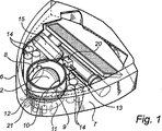
図1〜図4では、ロボット真空掃除機の形態の本発明によるロボット清掃装置が示されている。真空掃除機は、ハウジングの形態である本体1を備えている。本体は、前方端部分3と左後端部分4と右後端部分5とを有する等辺三角形ブロックの全体的形状を有している。これら三つの端部分3、4、5は、三つの丸いコーナー部分を形成している。左側壁7は、前方端部分3から左後端部分4へ延びており、右側壁6は、前方端部分3から右後端部分5へ延びている。左側壁6と右側壁7とは、二つで前方端部分3を介して左後端部分4から右後端部分5に延びる連続的バンパーを形成している。バンパーは、本体1の可撓性取付け部分である。最後に、後方側壁17は、左後端部分4から右後端部分5に延びている。
1 to 4 show a robot cleaning device according to the present invention in the form of a robot vacuum cleaner. The vacuum cleaner includes a body 1 in the form of a housing. The body has the general shape of an equilateral triangular block having a
バンパーは、いくつかのセンサ21と協働している。各センサ21はバンパーがいつ押されたかを記録する。これは、ロボット真空掃除機が障害物内で衝突したときに発生する。こうして、バンパーとセンサとが、障害物探知手段として機能している。
The bumper cooperates with
本体1は、前方端部分3に取付けられた操舵可能な駆動車輪2を含む制御可能な駆動手段を収容している。駆動車輪2は、車輪シャフト9回りに回転可能であり、ロボット真空掃除機を駆動するための電動式駆動モータ8によって車輪シャフト9回りに回転させられる。車輪シャフト9と駆動モータ8とは第一のリング部材10に固定されており、第一のリング部材10は、第二の静止したリング部材11に回転可能に取り付けられている。第一のリング部材10は、第二の静止したリング部材11上を滑走する間に、中心垂直軸線回りに回転することが出来る。第一のリング部材10は、外部鋸歯状のリング部材12を備えている。電動式操舵モータ13が、第一のリング部材10を回転するために鋸歯状リング12に接続されている。こうして、操舵モータ13が、第一のリング部材10を回転するように操作されると、操舵可能な駆動車輪が、垂直軸線回りに旋回させられ、この結果、駆動方向が変化され、真空掃除機が回転される。
The main body 1 contains controllable drive means including a
電動式駆動モータ8と電動式操舵モータ13とに電力を供給するために、一組の充電可能な電池14が、本体1に設けられている。
In order to supply electric power to the electric drive motor 8 and the
ロボット真空掃除機は、真空手段の形態である清掃手段をさらに含んでいる。真空手段は、吸引スリット16を介して掃除された表面から埃及び破片を吸引する吸引ファン15を含んでいる。吸引スリットは、その真空掃除機の最も幅広となる部分において、例えば、後方部分において、真空掃除機のほぼ幅全体にわたって延びている。吸引スリット16が、通路によってごみ箱18に接続されている。ごみ箱18とブラシロール19との入り口を備える通路は、吸引スリット16のほぼ長さ全体にわたって延びている。その結果、集収された埃及び破片は、真空掃除機の側面方向に移動される必要が無く、ごみ箱18に入込むために所定の小さい高さ持ち上げられる必要があるだけである。こうして、埃及び破片を集収するために必要とされるエネルギーは、低いレベルに保持されている。これは、本発明による真空掃除機の低いエネルギー消費に寄与し且つ電池時間を延ばしている。
The robot vacuum cleaner further includes cleaning means in the form of vacuum means. The vacuum means includes a
最後に、真空手段は、ごみ箱18の任意の集収された埃又は破片から吸引ファン15を防御するフィルタ19を含んでいる。
Finally, the vacuum means includes a
超小型演算処理装置20の形態の制御手段が、駆動モータ8と操舵モータ13とセンサ21に動作上接続されている。
Control means in the form of a micro-computing device 20 is operatively connected to the drive motor 8, the
図6〜図8を参照し、最後に、ロボット真空掃除機は、固定された旋回可能でない支持車輪26の形態である支持手段を備えている。
6-8, finally, the robotic vacuum cleaner is provided with support means in the form of a fixed
図5では、本発明によるロボット真空掃除機の回転特性が例示されている。主要左回転軸線23が、左後端部分4に位置しており、主要右回転軸線24が、右後端部分5に位置している。左側壁7が、主要右回転軸線24と一致する曲率中心を有する円弧として形成されており、右側壁6は、主要左回転軸線23と一致する曲率中心を有する円弧として形成されている。
FIG. 5 illustrates the rotational characteristics of the robot vacuum cleaner according to the present invention. The main
図5を参照すると、ロボット真空掃除機の真直ぐ前方に位置した障害物25を回避するために、真空掃除機は、主要回転軸線23、24の一つ回りに回転される。そのため、側壁の外形は、障害物25に対して所定の距離を維持する対応する円形に沿って移動される。結果として、本体1の少しの後方部分も、回転の間に障害物に引っかかることが無く、真空掃除機は、スライドすること無しに回転動作のみによって避けて移動することが出来る。
Referring to FIG. 5, the vacuum cleaner is rotated about one of the main
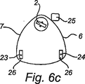
図6〜図8を参照すると、本発明の記載された実施形態による真空掃除機の操作が、記載されている。 With reference to FIGS. 6-8, the operation of a vacuum cleaner according to the described embodiment of the invention will be described.
図6では、右側で障害物25に遭遇するときに、ロボット真空掃除機の回転を例示する連続図である。図6では、真空掃除機が、真直ぐ前方向に移動される。バンパー及びセンサ21の形態である探知手段が、衝撃を記録するときに、本体1の右側の障害物25の存在は、制御手段20に送信される。次に、制御手段が、操舵モータ13を起動させ、操舵可能な駆動車輪が旋回されるように第一のリング部材10を回転させる。この結果、図6cを参照すると、操舵可能な駆動車輪の駆動方向が、左にほぼ45°回転される。この新しい駆動方向は、駆動車輪2の中心と主要左回転軸線23とから引かれるラインに垂直である。結果的に、ロボット真空掃除機は、主要左回転軸線23を回りに左回転を開始する。
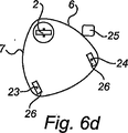
FIG. 6 is a continuous view illustrating the rotation of the robot vacuum cleaner when encountering an
図6dを参照すると、円弧形成側壁6と主要左回転軸線23の位置との組み合わせによると、真空掃除機は、この回転動作のみによって障害物を避けて移動される。図6eに示されるように、真空掃除機は、ほぼ60°回転が作動された後で、障害物から完全に束縛を受けていない。その後、制御手段20は、前方駆動位置に戻り、又は任意の他の適した駆動方向が選択される操舵御可能な駆動車輪2を旋回するように操舵モータ13を作動させることが出来る。この障害物回避回転の間に、駆動車輪は、一定の回転数で連続的に回転されており、こうして真空掃除機の速度を維持している。さらに、重量のある構成要素、電池14、駆動モータ8、操舵モータ13、吸引ファン15のような要素を本体1の前方端部に集中させることによって、真空掃除機は、主要左回転軸線23回りに回転する間にこれら構成要素からの推進力から利益を享受する。
Referring to FIG. 6d, according to the combination of the arc-shaped
図7では、両側部で障害物25、25’と遭遇するときに、ロボット真空掃除機の回転する連続的な例示が示されている。右側で第一の障害物を回避するために左に回転されるときに、真空掃除機が、左側で第二の障害物25’と衝突するならば、制御手段が、図6dの位置からほぼ90°回転するために駆動車輪2を回転するように駆動される。その中で、駆動車輪は、新しい駆動方向を取得し、この方向は、前方駆動方向の右にほぼ45°の方向が付けられている。この新しい駆動方向は、駆動車輪2の中心と主要右回転軸線24から引かれるラインに垂直である。結果的に、ロボット真空掃除機は、主要右回転軸線24回りに右に回転を開始する。
FIG. 7 shows a continuous illustration of the rotation of the robot vacuum cleaner when encountering
主要回転軸線23、24の位置する円弧形成側壁6、7の組み合わせによると、真空掃除機は、回転動作のみによって両方の障害物25、25’から避けるように移動され、例えば、最初に主要左回転軸線23回りに左回転され、次に主要右回転軸線24回りに右回転される。各回転は、ほぼ60°の角度にわたって広がっている。図7cでは、真空掃除機は、障害物25、25’の間に所定の位置に示されており、真空掃除機は、ほとんど完全に束縛を受けない。この位置では、制御手段20は、前方駆動位置に戻る操舵可能な駆動車輪2を旋回するための操舵モータ13を駆動させることができ、真空掃除機は、清掃運転を継続する。
According to the combination of the arc-shaped
二つの障害物25と25’との間の距離は、図8による例示にあるように、真空掃除機の幅よりもより小さくすべきであり、右側壁は、真空掃除機が、第二の障害物25’から向きを変えるために主要右回転軸線回りに右回りに回転を開始するときに、再び第一の障害物25に衝突する。その結果、制御手段20は、真空掃除機が、障害物25、25’との間を通過することができないことが理解される。この状況では、真空掃除機が、二つの非常に狭小な障害物25と障害物25’との間に捕捉される。真空掃除機は、前述の回転操作によって避けるように移動することが出来ないが、逆回転することにより、改めて始動される。
The distance between the two
Claims (16)
該主要本体が、
表面上で前記装置を移動させるように構成された制御可能な駆動手段と、
前記装置が表面上を移動させられるとき、表面を清掃するように構成された清掃手段と、
障害物探知手段と、
前記駆動手段と前記障害物探知手段とに接続された制御手段と、
を収容しており、
前記主要本体が、左後端部分と前方端部分を接続する左側壁と、右後端部分と前記前方端部分を接続する右側壁とを有し、
前記制御手段は、探知された障害物について前記障害物探知手段から情報を受信するとき、前記装置が、前記駆動手段を制御して、前記左後端部分に位置する主要左回転軸線と、前記右後端部分に位置する主要右回転軸線とのうちの一つ回りに前記装置を回転させ、実質的に前記主要左回転軸線と前記主要右回転軸線とのうちの一つの回りの回転動作のみを実行するように、構成されており、
前記左側壁と前記右側壁とは、前記装置が、前記回転動作によって、探知された障害物避けて移動されるように構成されていることを特徴とするロボット清掃装置。A robot cleaning device having a main body,
The main body is
Controllable drive means configured to move the device over a surface;
Cleaning means configured to clean the surface when the device is moved over the surface;
Obstacle detection means,
Control means connected to the drive means and the obstacle detection means;
Contain
The main body has a left side wall connecting the left rear end part and the front end part; and a right side wall connecting the right rear end part and the front end part;
Wherein, when the detected obstacle and receive information from the obstacle detecting means, the apparatus controls the pre-Symbol driving means, a main left rotational axis located at the left rear end portion, Rotating the device about one of a main right rotation axis located at the right rear end portion and substantially rotating around one of the main left rotation axis and the main right rotation axis Is configured to run only ,
The robot cleaning apparatus according to claim 1, wherein the left side wall and the right side wall are configured such that the apparatus is moved while avoiding the detected obstacle by the rotation operation.
前記2つの支持手段(26)は各々、前記主要左回転軸線と前記主要右回転軸線を形成する請求項1から請求項11の何れか一項に記載のロボット清掃装置。The drive means includes two support means (26) that have low friction in the main forward drive direction and high friction in both directions of an axis perpendicular to the main forward drive direction ;
The robot cleaning apparatus according to any one of claims 1 to 11 , wherein each of the two support means (26) forms the main left rotation axis and the main right rotation axis .
Applications Claiming Priority (3)
| Application Number | Priority Date | Filing Date | Title |
|---|---|---|---|
| SE0501613-4 | 2005-07-08 | ||
| SE0501613 | 2005-07-08 | ||
| PCT/SE2006/000847 WO2007008148A1 (en) | 2005-07-08 | 2006-07-06 | Robotic cleaning device |
Publications (3)
| Publication Number | Publication Date |
|---|---|
| JP2009500741A JP2009500741A (en) | 2009-01-08 |
| JP2009500741A5 JP2009500741A5 (en) | 2009-06-18 |
| JP5048663B2 true JP5048663B2 (en) | 2012-10-17 |
Family
ID=37637410
Family Applications (1)
| Application Number | Title | Priority Date | Filing Date |
|---|---|---|---|
| JP2008520218A Active JP5048663B2 (en) | 2005-07-08 | 2006-07-06 | Robot cleaning device |
Country Status (7)
| Country | Link |
|---|---|
| US (1) | US8032978B2 (en) |
| EP (1) | EP1906807B1 (en) |
| JP (1) | JP5048663B2 (en) |
| KR (1) | KR101322970B1 (en) |
| CN (1) | CN100586356C (en) |
| AT (1) | ATE542459T1 (en) |
| WO (1) | WO2007008148A1 (en) |
Families Citing this family (59)
| Publication number | Priority date | Publication date | Assignee | Title |
|---|---|---|---|---|
| CN101816533B (en) * | 2009-02-27 | 2012-08-01 | 和硕联合科技股份有限公司 | Adjustable dust collecting box and dust absorption device thereof |
| JP5037549B2 (en) * | 2009-03-10 | 2012-09-26 | 東芝テック株式会社 | Autonomous mobile device |
| DE102009049637A1 (en) * | 2009-10-15 | 2011-04-28 | Carl Freudenberg Kg | Cleaning robot for cleaning e.g. narrow points of room, has cleaning cloth flexibly formed in area in which cloth outwardly protrudes from guiding surface, and housing formed as regular polygon or hexagon |
| DE102010045096A1 (en) * | 2010-09-13 | 2012-03-15 | Carl Freudenberg Kg | Drive system for a cleaning device and cleaning device |
| JP5832553B2 (en) * | 2010-12-30 | 2015-12-16 | アイロボット コーポレイション | Coverage robot navigation |
| PL394570A1 (en) | 2011-04-15 | 2012-10-22 | Robotics Inventions Spólka Z Ograniczona Odpowiedzialnoscia | Robot for raised floors and method for raised floor maintenance |
| KR101566207B1 (en) * | 2011-06-28 | 2015-11-13 | 삼성전자 주식회사 | Robot cleaner and control method thereof |
| US8930493B2 (en) | 2012-03-20 | 2015-01-06 | International Business Machines Corporation | Inter-domain replication of service information |
| JP6068823B2 (en) * | 2012-04-27 | 2017-01-25 | シャープ株式会社 | Self-propelled vacuum cleaner |
| JP2013231536A (en) * | 2012-04-27 | 2013-11-14 | Sharp Corp | Self-propelled air cleaner |
| JP6071251B2 (en) * | 2012-05-30 | 2017-02-01 | 三菱電機株式会社 | Self-propelled vacuum cleaner |
| DE102012107765B4 (en) * | 2012-08-23 | 2020-02-13 | Miele & Cie. Kg | Robotic vacuum and method for operating a robotic vacuum |
| JP6202544B2 (en) | 2012-08-27 | 2017-09-27 | アクティエボラゲット エレクトロラックス | Robot positioning system |
| US9615714B2 (en) * | 2012-11-09 | 2017-04-11 | Samsung Electronics Co., Ltd. | Autonomous cleaning device |
| US10111563B2 (en) | 2013-01-18 | 2018-10-30 | Sunpower Corporation | Mechanism for cleaning solar collector surfaces |
| WO2014157974A1 (en) * | 2013-03-28 | 2014-10-02 | (주)유진로봇 | Cleaning robot having expanded cleaning territory |
| US10448794B2 (en) | 2013-04-15 | 2019-10-22 | Aktiebolaget Electrolux | Robotic vacuum cleaner |
| CN105101855A (en) * | 2013-04-15 | 2015-11-25 | 伊莱克斯公司 | Robotic vacuum cleaner with protruding sidebrush |
| CN203987872U (en) | 2013-06-03 | 2014-12-10 | 碧洁家庭护理有限公司 | Autonomous type floor cleaning equipment |
| USD744705S1 (en) * | 2013-10-24 | 2015-12-01 | Aktiebolaget Electrolux | Vacuum cleaner |
| US11235893B2 (en) | 2013-12-05 | 2022-02-01 | The Boeing Company | End effector for cleaning objects having multiple surfaces |
| US9946263B2 (en) | 2013-12-19 | 2018-04-17 | Aktiebolaget Electrolux | Prioritizing cleaning areas |
| KR102137857B1 (en) | 2013-12-19 | 2020-07-24 | 에이비 엘렉트로룩스 | Robotic cleaning device and method for landmark recognition |
| US10045675B2 (en) | 2013-12-19 | 2018-08-14 | Aktiebolaget Electrolux | Robotic vacuum cleaner with side brush moving in spiral pattern |
| KR102124235B1 (en) | 2013-12-19 | 2020-06-24 | 에이비 엘렉트로룩스 | Robotic cleaning device with perimeter recording function |
| US10149589B2 (en) | 2013-12-19 | 2018-12-11 | Aktiebolaget Electrolux | Sensing climb of obstacle of a robotic cleaning device |
| US10433697B2 (en) | 2013-12-19 | 2019-10-08 | Aktiebolaget Electrolux | Adaptive speed control of rotating side brush |
| WO2015090397A1 (en) | 2013-12-19 | 2015-06-25 | Aktiebolaget Electrolux | Robotic cleaning device |
| EP3082539B1 (en) | 2013-12-20 | 2019-02-20 | Aktiebolaget Electrolux | Dust container |
| WO2015090437A1 (en) * | 2013-12-20 | 2015-06-25 | Aktiebolaget Electrolux | Autonomous cleaner |
| CN104000541B (en) * | 2014-06-16 | 2016-05-04 | 成都北斗群星智能科技有限公司 | Support sweeping robot and threshold detection method that threshold detects |
| JP6167316B2 (en) * | 2014-06-30 | 2017-07-26 | パナソニックIpマネジメント株式会社 | Autonomous traveling vacuum cleaner |
| EP3167341B1 (en) | 2014-07-10 | 2018-05-09 | Aktiebolaget Electrolux | Method for detecting a measurement error in a robotic cleaning device |
| EP3190938A1 (en) | 2014-09-08 | 2017-07-19 | Aktiebolaget Electrolux | Robotic vacuum cleaner |
| US10499778B2 (en) | 2014-09-08 | 2019-12-10 | Aktiebolaget Electrolux | Robotic vacuum cleaner |
| WO2016056226A1 (en) * | 2014-10-10 | 2016-04-14 | パナソニックIpマネジメント株式会社 | Autonomous travel-type cleaner |
| JP2017213009A (en) | 2014-10-10 | 2017-12-07 | パナソニックIpマネジメント株式会社 | Autonomous travel type cleaner |
| JP1531010S (en) * | 2014-10-22 | 2015-08-17 | ||
| WO2016071579A1 (en) * | 2014-11-04 | 2016-05-12 | France Reducteurs | Automatically moving wheeled vehicle without a driver seated or walking behind the vehicle, also called a robot |
| US10877484B2 (en) | 2014-12-10 | 2020-12-29 | Aktiebolaget Electrolux | Using laser sensor for floor type detection |
| WO2016091320A1 (en) | 2014-12-12 | 2016-06-16 | Aktiebolaget Electrolux | Side brush and robotic cleaner |
| JP6532530B2 (en) | 2014-12-16 | 2019-06-19 | アクチエボラゲット エレクトロルックス | How to clean a robot vacuum cleaner |
| CN107003669B (en) | 2014-12-16 | 2023-01-31 | 伊莱克斯公司 | Experience-based road sign for robotic cleaning devices |
| JP6743828B2 (en) | 2015-04-17 | 2020-08-19 | アクチエボラゲット エレクトロルックス | Robot vacuum and method for controlling the robot vacuum |
| JP6476077B2 (en) * | 2015-06-18 | 2019-02-27 | シャープ株式会社 | Self-propelled electronic device and traveling method of the self-propelled electronic device |
| KR102445064B1 (en) | 2015-09-03 | 2022-09-19 | 에이비 엘렉트로룩스 | system of robot cleaning device |
| US9582001B1 (en) * | 2015-10-07 | 2017-02-28 | X Development Llc | Motor system for vehicle steering and locomotion |
| CN106913290B (en) * | 2015-12-25 | 2020-09-25 | 北京奇虎科技有限公司 | Sweeper and control method based on sweeper |
| TWI680739B (en) * | 2016-02-05 | 2020-01-01 | 金寶電子工業股份有限公司 | Protection device of self-propelled vehicle |
| JP7035300B2 (en) | 2016-03-15 | 2022-03-15 | アクチエボラゲット エレクトロルックス | Robot Cleaning Devices, Methods for Performing Escarpment Detection in Robot Cleaning Devices, Computer Programs, and Computer Program Products |
| WO2017194102A1 (en) | 2016-05-11 | 2017-11-16 | Aktiebolaget Electrolux | Robotic cleaning device |
| US20180329409A1 (en) * | 2017-05-11 | 2018-11-15 | Bot3, Inc. | Portable mobile robot and operation thereof |
| WO2018219473A1 (en) | 2017-06-02 | 2018-12-06 | Aktiebolaget Electrolux | Method of detecting a difference in level of a surface in front of a robotic cleaning device |
| WO2019063066A1 (en) | 2017-09-26 | 2019-04-04 | Aktiebolaget Electrolux | Controlling movement of a robotic cleaning device |
| CN109808789A (en) * | 2017-11-21 | 2019-05-28 | 富泰华工业(深圳)有限公司 | Wheeled mobile robot it is anti-walk deflection device |
| CN108523774B (en) * | 2018-05-11 | 2020-08-28 | 安徽大江服装服饰有限公司 | Wall-touching type spraying device for floor sweeping robot |
| US10888204B2 (en) | 2019-05-29 | 2021-01-12 | Maniff Creations, Inc. | Removable cover for a robotic cleaning device |
| USD924508S1 (en) * | 2019-05-30 | 2021-07-06 | Trifo, Inc. | Home robot |
| WO2022087404A1 (en) | 2020-10-23 | 2022-04-28 | Sharkninja Operating Llc | Robotic cleaner |
Family Cites Families (28)
| Publication number | Priority date | Publication date | Assignee | Title |
|---|---|---|---|---|
| JPS62120510A (en) * | 1985-11-21 | 1987-06-01 | Hitachi Ltd | Control method for automatic cleaner |
| FR2620070A2 (en) * | 1986-12-11 | 1989-03-10 | Jonas Andre | AUTOBULATED MOBILE UNIT AND CLEANING APPARATUS SUCH AS A VACUUM COMPRISING SUCH A UNIT |
| JPH0786767B2 (en) * | 1987-03-30 | 1995-09-20 | 株式会社日立製作所 | Travel control method for self-propelled robot |
| JPH03166074A (en) * | 1989-11-27 | 1991-07-18 | Sony Corp | Self advancing robot |
| US5023444A (en) | 1989-12-28 | 1991-06-11 | Aktiebolaget Electrolux | Machine proximity sensor |
| US5307273A (en) * | 1990-08-29 | 1994-04-26 | Goldstar Co., Ltd. | Apparatus and method for recognizing carpets and stairs by cleaning robot |
| KR930000081B1 (en) * | 1990-12-07 | 1993-01-08 | 주식회사 금성사 | Cleansing method of electric vacuum cleaner |
| JP3282206B2 (en) * | 1992-01-14 | 2002-05-13 | 松下電器産業株式会社 | Obstacle detection device for mobile work robot |
| KR940004375B1 (en) * | 1992-03-25 | 1994-05-23 | 삼성전자 주식회사 | Drive system for automatic vacuum cleaner |
| JPH06144215A (en) * | 1992-10-30 | 1994-05-24 | Meidensha Corp | Unmanned carriage |
| JPH06179145A (en) * | 1992-12-10 | 1994-06-28 | Toyoda Mach Works Ltd | Conveying truck |
| KR0140499B1 (en) * | 1993-08-07 | 1998-07-01 | 김광호 | Vacuum cleaner and control method |
| SE502834C2 (en) | 1994-03-29 | 1996-01-29 | Electrolux Ab | Method and apparatus for detecting obstacles in self-propelled apparatus |
| SE514791C2 (en) | 1994-06-06 | 2001-04-23 | Electrolux Ab | Improved method for locating lighthouses in self-propelled equipment |
| JPH08326025A (en) * | 1995-05-31 | 1996-12-10 | Tokico Ltd | Cleaning robot |
| JPH09150741A (en) * | 1995-11-29 | 1997-06-10 | Toyota Auto Body Co Ltd | Electric truck for transporting heavy cargo |
| US5935179A (en) | 1996-04-30 | 1999-08-10 | Aktiebolaget Electrolux | System and device for a self orienting device |
| SE506372C2 (en) | 1996-04-30 | 1997-12-08 | Electrolux Ab | Self-propelled device |
| US6226830B1 (en) | 1997-08-20 | 2001-05-08 | Philips Electronics North America Corp. | Vacuum cleaner with obstacle avoidance |
| SE510524C2 (en) | 1997-09-19 | 1999-05-31 | Electrolux Ab | Electronic demarcation system |
| SE511254C2 (en) | 1998-01-08 | 1999-09-06 | Electrolux Ab | Electronic search system for work tools |
| US7155308B2 (en) * | 2000-01-24 | 2006-12-26 | Irobot Corporation | Robot obstacle detection system |
| JP2003280740A (en) * | 2002-03-25 | 2003-10-02 | Matsushita Electric Ind Co Ltd | Movable device |
| WO2004025947A2 (en) * | 2002-09-13 | 2004-03-25 | Irobot Corporation | A navigational control system for a robotic device |
| KR100492588B1 (en) * | 2003-01-23 | 2005-06-03 | 엘지전자 주식회사 | Position information recognition apparatus for automatic running vacuum cleaner |
| AU2004202834B2 (en) | 2003-07-24 | 2006-02-23 | Samsung Gwangju Electronics Co., Ltd. | Robot Cleaner |
| ES2346343T3 (en) * | 2005-02-18 | 2010-10-14 | Irobot Corporation | AUTONOMOUS SURFACE CLEANING ROBOT FOR DRY AND WET CLEANING. |
| US20060200281A1 (en) * | 2005-02-18 | 2006-09-07 | Andrew Ziegler | Autonomous surface cleaning robot for wet and dry cleaning |
-
2006
- 2006-07-06 US US11/995,071 patent/US8032978B2/en not_active Expired - Fee Related
- 2006-07-06 AT AT06747992T patent/ATE542459T1/en active
- 2006-07-06 WO PCT/SE2006/000847 patent/WO2007008148A1/en active Application Filing
- 2006-07-06 KR KR1020087002671A patent/KR101322970B1/en active IP Right Grant
- 2006-07-06 EP EP06747992A patent/EP1906807B1/en active Active
- 2006-07-06 CN CN200680024913A patent/CN100586356C/en active Active
- 2006-07-06 JP JP2008520218A patent/JP5048663B2/en active Active
Also Published As
| Publication number | Publication date |
|---|---|
| EP1906807A1 (en) | 2008-04-09 |
| ATE542459T1 (en) | 2012-02-15 |
| EP1906807B1 (en) | 2012-01-25 |
| KR101322970B1 (en) | 2013-10-29 |
| CN101217907A (en) | 2008-07-09 |
| CN100586356C (en) | 2010-02-03 |
| US20090126143A1 (en) | 2009-05-21 |
| US8032978B2 (en) | 2011-10-11 |
| JP2009500741A (en) | 2009-01-08 |
| WO2007008148A1 (en) | 2007-01-18 |
| KR20080028988A (en) | 2008-04-02 |
| EP1906807A4 (en) | 2011-03-09 |
Similar Documents
| Publication | Publication Date | Title |
|---|---|---|
| JP5048663B2 (en) | Robot cleaning device | |
| US11014460B2 (en) | Compact autonomous coverage robot | |
| CN111163671B (en) | Robot cleaner | |
| JP6599604B2 (en) | Electric vacuum cleaner | |
| JP2005021665A (en) | Driving device of robot cleaner | |
| JP2004529686A (en) | Autonomously moving canister type vacuum cleaner | |
| JP2004195215A5 (en) | ||
| JPH07295636A (en) | Traveling controller of robot vacuum cleaner and its control method | |
| JPH0732751B2 (en) | Self-propelled vacuum cleaner | |
| WO2016056226A1 (en) | Autonomous travel-type cleaner | |
| JP2017213009A (en) | Autonomous travel type cleaner | |
| CN110710920B (en) | Robotic vacuum cleaner with extended side brush | |
| KR20150141980A (en) | Robotic vacuum cleaner | |
| JP2017153787A (en) | Self-travel type vacuum cleaner | |
| CN109700379B (en) | Autonomous walking type dust collector | |
| JP6685740B2 (en) | Vacuum cleaner | |
| JP2004275304A (en) | Self-traveling type cleaner | |
| KR100514993B1 (en) | unmanned sweeping unit | |
| JP7396197B2 (en) | vacuum cleaner | |
| KR102662324B1 (en) | robotic vacuum | |
| KR200324625Y1 (en) | unmanned sweeping unit | |
| KR20040087579A (en) | Obstacle detection apparatus for mobile robot | |
| JP2020074918A (en) | Robotic dust collector | |
| KR20150075638A (en) | Robot Cleaner |
Legal Events
| Date | Code | Title | Description |
|---|---|---|---|
| A521 | Request for written amendment filed |
Free format text: JAPANESE INTERMEDIATE CODE: A523 Effective date: 20090421 |
|
| A621 | Written request for application examination |
Free format text: JAPANESE INTERMEDIATE CODE: A621 Effective date: 20090421 |
|
| A977 | Report on retrieval |
Free format text: JAPANESE INTERMEDIATE CODE: A971007 Effective date: 20110823 |
|
| A131 | Notification of reasons for refusal |
Free format text: JAPANESE INTERMEDIATE CODE: A131 Effective date: 20110906 |
|
| A601 | Written request for extension of time |
Free format text: JAPANESE INTERMEDIATE CODE: A601 Effective date: 20111205 |
|
| A602 | Written permission of extension of time |
Free format text: JAPANESE INTERMEDIATE CODE: A602 Effective date: 20111212 |
|
| A521 | Request for written amendment filed |
Free format text: JAPANESE INTERMEDIATE CODE: A523 Effective date: 20120127 |
|
| TRDD | Decision of grant or rejection written | ||
| A01 | Written decision to grant a patent or to grant a registration (utility model) |
Free format text: JAPANESE INTERMEDIATE CODE: A01 Effective date: 20120619 |
|
| A01 | Written decision to grant a patent or to grant a registration (utility model) |
Free format text: JAPANESE INTERMEDIATE CODE: A01 |
|
| A61 | First payment of annual fees (during grant procedure) |
Free format text: JAPANESE INTERMEDIATE CODE: A61 Effective date: 20120719 |
|
| FPAY | Renewal fee payment (event date is renewal date of database) |
Free format text: PAYMENT UNTIL: 20150727 Year of fee payment: 3 |
|
| R150 | Certificate of patent or registration of utility model |
Ref document number: 5048663 Country of ref document: JP Free format text: JAPANESE INTERMEDIATE CODE: R150 Free format text: JAPANESE INTERMEDIATE CODE: R150 |
|
| R250 | Receipt of annual fees |
Free format text: JAPANESE INTERMEDIATE CODE: R250 |
|
| R250 | Receipt of annual fees |
Free format text: JAPANESE INTERMEDIATE CODE: R250 |
|
| R250 | Receipt of annual fees |
Free format text: JAPANESE INTERMEDIATE CODE: R250 |
|
| R250 | Receipt of annual fees |
Free format text: JAPANESE INTERMEDIATE CODE: R250 |
|
| R250 | Receipt of annual fees |
Free format text: JAPANESE INTERMEDIATE CODE: R250 |
|
| R250 | Receipt of annual fees |
Free format text: JAPANESE INTERMEDIATE CODE: R250 |
|
| R250 | Receipt of annual fees |
Free format text: JAPANESE INTERMEDIATE CODE: R250 |
|
| R250 | Receipt of annual fees |
Free format text: JAPANESE INTERMEDIATE CODE: R250 |
|
| R250 | Receipt of annual fees |
Free format text: JAPANESE INTERMEDIATE CODE: R250 |