EP1906807B1 - Robotic cleaning device - Google Patents
Robotic cleaning device Download PDFInfo
- Publication number
- EP1906807B1 EP1906807B1 EP06747992A EP06747992A EP1906807B1 EP 1906807 B1 EP1906807 B1 EP 1906807B1 EP 06747992 A EP06747992 A EP 06747992A EP 06747992 A EP06747992 A EP 06747992A EP 1906807 B1 EP1906807 B1 EP 1906807B1
- Authority
- EP
- European Patent Office
- Prior art keywords
- cleaning device
- end portion
- side wall
- main
- robotic cleaning
- Prior art date
- Legal status (The legal status is an assumption and is not a legal conclusion. Google has not performed a legal analysis and makes no representation as to the accuracy of the status listed.)
- Active
Links
- 238000004140 cleaning Methods 0.000 title claims abstract description 112
- 238000010407 vacuum cleaning Methods 0.000 claims 1
- 239000000428 dust Substances 0.000 description 5
- 230000008901 benefit Effects 0.000 description 3
- 238000005265 energy consumption Methods 0.000 description 3
- 230000005484 gravity Effects 0.000 description 3
- 230000001133 acceleration Effects 0.000 description 1
- 230000009194 climbing Effects 0.000 description 1
- 238000001514 detection method Methods 0.000 description 1
- 230000002349 favourable effect Effects 0.000 description 1
- 230000014509 gene expression Effects 0.000 description 1
- 238000000034 method Methods 0.000 description 1
- 238000005498 polishing Methods 0.000 description 1
- 230000007306 turnover Effects 0.000 description 1
Images


Classifications
-
- A—HUMAN NECESSITIES
- A47—FURNITURE; DOMESTIC ARTICLES OR APPLIANCES; COFFEE MILLS; SPICE MILLS; SUCTION CLEANERS IN GENERAL
- A47L—DOMESTIC WASHING OR CLEANING; SUCTION CLEANERS IN GENERAL
- A47L9/00—Details or accessories of suction cleaners, e.g. mechanical means for controlling the suction or for effecting pulsating action; Storing devices specially adapted to suction cleaners or parts thereof; Carrying-vehicles specially adapted for suction cleaners
-
- A—HUMAN NECESSITIES
- A47—FURNITURE; DOMESTIC ARTICLES OR APPLIANCES; COFFEE MILLS; SPICE MILLS; SUCTION CLEANERS IN GENERAL
- A47L—DOMESTIC WASHING OR CLEANING; SUCTION CLEANERS IN GENERAL
- A47L11/00—Machines for cleaning floors, carpets, furniture, walls, or wall coverings
- A47L11/40—Parts or details of machines not provided for in groups A47L11/02 - A47L11/38, or not restricted to one of these groups, e.g. handles, arrangements of switches, skirts, buffers, levers
-
- A—HUMAN NECESSITIES
- A47—FURNITURE; DOMESTIC ARTICLES OR APPLIANCES; COFFEE MILLS; SPICE MILLS; SUCTION CLEANERS IN GENERAL
- A47L—DOMESTIC WASHING OR CLEANING; SUCTION CLEANERS IN GENERAL
- A47L9/00—Details or accessories of suction cleaners, e.g. mechanical means for controlling the suction or for effecting pulsating action; Storing devices specially adapted to suction cleaners or parts thereof; Carrying-vehicles specially adapted for suction cleaners
- A47L9/009—Carrying-vehicles; Arrangements of trollies or wheels; Means for avoiding mechanical obstacles
-
- A—HUMAN NECESSITIES
- A47—FURNITURE; DOMESTIC ARTICLES OR APPLIANCES; COFFEE MILLS; SPICE MILLS; SUCTION CLEANERS IN GENERAL
- A47L—DOMESTIC WASHING OR CLEANING; SUCTION CLEANERS IN GENERAL
- A47L9/00—Details or accessories of suction cleaners, e.g. mechanical means for controlling the suction or for effecting pulsating action; Storing devices specially adapted to suction cleaners or parts thereof; Carrying-vehicles specially adapted for suction cleaners
- A47L9/28—Installation of the electric equipment, e.g. adaptation or attachment to the suction cleaner; Controlling suction cleaners by electric means
-
- B—PERFORMING OPERATIONS; TRANSPORTING
- B60—VEHICLES IN GENERAL
- B60K—ARRANGEMENT OR MOUNTING OF PROPULSION UNITS OR OF TRANSMISSIONS IN VEHICLES; ARRANGEMENT OR MOUNTING OF PLURAL DIVERSE PRIME-MOVERS IN VEHICLES; AUXILIARY DRIVES FOR VEHICLES; INSTRUMENTATION OR DASHBOARDS FOR VEHICLES; ARRANGEMENTS IN CONNECTION WITH COOLING, AIR INTAKE, GAS EXHAUST OR FUEL SUPPLY OF PROPULSION UNITS IN VEHICLES
- B60K17/00—Arrangement or mounting of transmissions in vehicles
- B60K17/30—Arrangement or mounting of transmissions in vehicles the ultimate propulsive elements, e.g. ground wheels, being steerable
-
- B—PERFORMING OPERATIONS; TRANSPORTING
- B60—VEHICLES IN GENERAL
- B60K—ARRANGEMENT OR MOUNTING OF PROPULSION UNITS OR OF TRANSMISSIONS IN VEHICLES; ARRANGEMENT OR MOUNTING OF PLURAL DIVERSE PRIME-MOVERS IN VEHICLES; AUXILIARY DRIVES FOR VEHICLES; INSTRUMENTATION OR DASHBOARDS FOR VEHICLES; ARRANGEMENTS IN CONNECTION WITH COOLING, AIR INTAKE, GAS EXHAUST OR FUEL SUPPLY OF PROPULSION UNITS IN VEHICLES
- B60K7/00—Disposition of motor in, or adjacent to, traction wheel
- B60K7/0007—Disposition of motor in, or adjacent to, traction wheel the motor being electric
-
- A—HUMAN NECESSITIES
- A47—FURNITURE; DOMESTIC ARTICLES OR APPLIANCES; COFFEE MILLS; SPICE MILLS; SUCTION CLEANERS IN GENERAL
- A47L—DOMESTIC WASHING OR CLEANING; SUCTION CLEANERS IN GENERAL
- A47L2201/00—Robotic cleaning machines, i.e. with automatic control of the travelling movement or the cleaning operation
- A47L2201/04—Automatic control of the travelling movement; Automatic obstacle detection
-
- B—PERFORMING OPERATIONS; TRANSPORTING
- B60—VEHICLES IN GENERAL
- B60K—ARRANGEMENT OR MOUNTING OF PROPULSION UNITS OR OF TRANSMISSIONS IN VEHICLES; ARRANGEMENT OR MOUNTING OF PLURAL DIVERSE PRIME-MOVERS IN VEHICLES; AUXILIARY DRIVES FOR VEHICLES; INSTRUMENTATION OR DASHBOARDS FOR VEHICLES; ARRANGEMENTS IN CONNECTION WITH COOLING, AIR INTAKE, GAS EXHAUST OR FUEL SUPPLY OF PROPULSION UNITS IN VEHICLES
- B60K7/00—Disposition of motor in, or adjacent to, traction wheel
- B60K2007/0038—Disposition of motor in, or adjacent to, traction wheel the motor moving together with the wheel axle
-
- B—PERFORMING OPERATIONS; TRANSPORTING
- B60—VEHICLES IN GENERAL
- B60K—ARRANGEMENT OR MOUNTING OF PROPULSION UNITS OR OF TRANSMISSIONS IN VEHICLES; ARRANGEMENT OR MOUNTING OF PLURAL DIVERSE PRIME-MOVERS IN VEHICLES; AUXILIARY DRIVES FOR VEHICLES; INSTRUMENTATION OR DASHBOARDS FOR VEHICLES; ARRANGEMENTS IN CONNECTION WITH COOLING, AIR INTAKE, GAS EXHAUST OR FUEL SUPPLY OF PROPULSION UNITS IN VEHICLES
- B60K7/00—Disposition of motor in, or adjacent to, traction wheel
- B60K2007/0092—Disposition of motor in, or adjacent to, traction wheel the motor axle being coaxial to the wheel axle
-
- G—PHYSICS
- G05—CONTROLLING; REGULATING
- G05D—SYSTEMS FOR CONTROLLING OR REGULATING NON-ELECTRIC VARIABLES
- G05D1/00—Control of position, course or altitude of land, water, air, or space vehicles, e.g. automatic pilot
- G05D1/02—Control of position or course in two dimensions
- G05D1/021—Control of position or course in two dimensions specially adapted to land vehicles
- G05D1/0227—Control of position or course in two dimensions specially adapted to land vehicles using mechanical sensing means, e.g. for sensing treated area
Abstract
Description
- The present invention relates to a robotic cleaning device, for example a robotic vacuum cleaner.
- Robotic cleaning devices, such as robotic vacuum cleaners, are known in the state of the art. One such robotic cleaning device is disclosed in
US 5 369 347 . This known device comprises a housing having an overall shape of a circular block. For driving the device, the device is provided with one driving wheel and two support wheels, which support wheels are arranged at diametrical opposite sides of the device. For steering the device, the driving wheel is pivoted round a vertical axis. - Such a known device can be operated in the following manner: When the device moves forwards, the driving wheel is oriented in parallel with the support wheels. If, for example, the device hits an obstacle on the left side thereof, the driving wheel is pivoted 90° to the right, whereby the device is brought to a complete halt before it will start to rotate. The rotation will be to the right and, because the support wheels are arranged on a diameter of the circular device, round a central axis between the support wheels. Furthermore, due to the round shape of the device, the obstacle will not obstruct the rotation of the device. When the devices have turned 90°, the driving wheel is pivoted 90° to the left and will again be parallel with the support wheels. The device will start to move forward and is allowed to travel a small distance. Then, the driving wheel is pivoted 90° to the left, wherein the device again is caused to stop before it starts to turn left round the central axis. After the device has turned 90° left, the driving wheel is pivoted back to being parallel with the support wheels and the device will again travel forward in the original direction.
- A problem with this known robotic cleaning device is that it is time and energy consuming to steer the device round obstacles, for example table legs or chair legs, which are common in normal home environment. This is especially a problem with battery operated robotic cleaning devices, since the batteries thereof often have to be reloaded, which extends the cleaning time even more.
- It is of cause also possible to rotate the driving wheel less then 90° when the device hits an obstacle. However, since the device in that case will not turn round a central axis, a problem with this way of operation is that the device will not move clear of the obstacle, but will be pushed backwards by the obstacle during the rotation or will even get stuck.
- Another robotic cleaning device is disclosed in
US 2004/020000 . - This robot cleaning system has a circular shape and a control system enabling the device to turn about varying radius points in order to smoothly follow a wall.
- It is therefore an object of the present invention to provide a robotic cleaning device that alleviates the above-mentioned problems.
- According to the invention, this object is achieved by a robotic cleaning device according to claim 1.
- A robotic cleaning device according to the invention comprises a main body which accommodates controllable drive means arranged to move the device over a surface, cleaning means arranged to clean the surface when the device is moved over the surface, obstacle detecting means, and control means connected to the drive means and the obstacle detecting means. The main body has a left side wall connecting a front end portion with a left rear end portion, and a right side wall connecting the front end portion with a right rear end portion, wherein a rear side wall connects the right with the left rear end portion. The control means, when receiving information from the obstacle detecting means about a detected obstacle, is arranged to control the drive means to rotate the device around one of a main left-turn axis located at the left rear end portion and a main right-turn axis located at the right rear end portion, such that the device performs substantially only turning motion round the one of said axes. The left side wall and the right side wall are configured such that the device is moved clear of the detected obstacle by said turning motion.
- Due to the cleaning device being arranged to rotate round one of two main turn axis in the rear portion of the device in combination with the side walls being configured in coordination with said rotation axis, the cleaning device is able to move clear from an obstacle without having to stop. In addition, this combination of turning axis locations and side wall configuration makes it possible to move the device clear of most obstacles by a turn less than 90°.
- In a normally furnished room in an average home, a cleaning robot will hit an obstacle about 20 - 60 times per minute. Because the cleaning device according to the invention can be operated with fewer decelerations and accelerations, and often can avoid obstacles with turns extending over a smaller angle than the prior art device, the cleaning device according to the invention can maintain a higher average speed when operated in a normal home. Furthermore, this higher average speed can be achieved with the same or less energy consumption as compared to the prior art device. It is thus possible to use the same or even smaller and/or less heavy batteries in the device according to the invention than in the prior art device. Consequently, the robotic cleaning device according to the invention is able to clean a room faster while consuming the same or less energy compared to the prior art device.
- The invention relates to robotic cleaning devices, or in other words to automatic, self-propelled machines for cleaning a surface. The robotic cleaning device according to the invention can be mains-operated and have a cord, be battery-operated or use any other kind of suitable energy source, for example solar energy.
- In this application, expressions like "left", right", "front" and "rear" are related to the normal travelling direction of the robotic cleaning device when in use.
- According to the invention, the robotic cleaning device comprises a cleaning means which is arranged to clean a surface when the robotic cleaning device is moved over a surface, wherein the surface travelled by the cleaning device not necessarily needs to be identical with the cleaned surface. The cleaning means can for example include vacuum means, swabbing means or polishing means. If the cleaning means are vacuum means, the robotic cleaning device according to the invention can be called a robotic vacuum cleaner. The cleaning device according to the invention is intended to be used on a mainly horizontal surface such as a floor, but the surface to be cleaned could also be an outdoor surface, for example a patio floor.
- The robotic cleaning device according to the invention comprises controllable drive means. The drive means includes means for propelling the cleaning device, for example an electric motor, and means for carrying the cleaning device, for example gliding means or wheels.
- The robotic cleaning device according to the invention comprises obstacle detecting means, for example a bumper connected to sensors, IR-means, and/or sonar means, a microwave radar, a camera registering its surroundings, a laser scanner, etc. for detecting obstacles and communicating information abut any detected obstacle to a control means.
- Furthermore, the robotic cleaning device according to the invention comprises control means, for example a microprocessor. The control means is connected to the obstacle detecting means and to the drive means such that said control means is able to receive information about an obstacle detected by the detection means and to control the drive means in response to the received information. According to one embodiment of the invention, the control means is able to process the information from the obstacle detecting means.
- According to the invention, these components of the robotic cleaning device, i.e. the controllable drive means, the cleaning means, the obstacle detecting means and the control means, are accommodated in a main body of the cleaning device. The main body can be a block shaped housing having a rather low height in relation to the lateral extension thereof such that it will fit in under pieces of furniture having short legs, for example beds and sofas. The components can be completely enclosed in the main body or protrude therefrom, wherein it is advantageous if any protruding components do not obstruct the cleaning device when driving in under furniture. The main body has a front end portion, a left rear end portion and a right rear end portion. A left side wall extends between the front end portion and the left rear end portion, a right side wall extends between the front end portion and the right rear end portion along respective sides of the main body. When the cleaning device is placed on a surface to be cleaned, the side walls are oriented such that any encountered obstacles in most cases will struck the side walls of the main body of the cleaning device unless the cleaning device is turned away in time.
- An obstacle can be any hindrance in a normally furnished room, for example a wall, a table leg or a chair leg.
- When an obstacle is detected, the control means is according to the invention arranged to control the drive means such that the cleaning device rotates around a main left-turn axis or a main right-turn axis in an obstacle avoiding operation. The control means can of course control the drive means to steer the cleaning device a round other axis or in a straight direction during other operations, for example during cleaning of areas with no obstacles. The main left-turn axis is located at the left rear end portion and the main right-turn axis is located at the right rear end portion. According to one embodiment of the invention, the respective main turn axes are located substantially on the periphery of the main body at respective rear end portions. According to the invention, the cleaning device can also be arranged to turn around main turn axes located outside of the main body at the respective end portion.
- According to the invention, the side walls of the main body are configured such that the cleaning device is moved clear from a detected obstacle when brought to rotate around one of said main turn axes. According to the invention, due to the location of the main turn axis and the corresponding shape of the side walls, the cleaning device is moved clear from the detected obstacle by the turning motion only. In other words, the cleaning device performs substantially only rotation and no translation during the obstacle avoiding turn. The cleaning device thus performs a "clean" turn without being forced to slide backwards by the obstacle.
- According to the invention, the cleaning device is moved clear from an obstacle when it is free to move unaffected by the obstacle in any forward direction.
- According to the invention the side walls can have such a shape that the side wall on the side where an obstacle is detected slides along the detected obstacle when the cleaning device turns around the corresponding one of the main turn axes. Alternatively, the side walls can have such a shape that the distance to the detected obstacle increases as the cleaning device turns. Another alternative according to the invention is to provide the side walls with flexible parts or flexibly mounted parts. When the cleaning device hits an obstacle with one side wall and starts to turn around the corresponding one of the main turn axes, the side wall can flex when pushed against the obstacle by the turning motion such that the cleaning device is moved clear without having to translate.
- According to one embodiment of the invention, the side walls are of essentially equal length and form a vertex between them at the front end portion. The main body can have a rounded front end such that the actual vertex is outside of the boundaries of the main body, i.e. in front of the main body. An advantage with this embodiment it is that the detecting means more easily can detect if an obstacle is located on the left or the right side in relation to the cleaning device. Thereby, the control means can be arranged to control the drive means to rotate the cleaning device round the main left-turn axis or the main right-turn axis in response to on which side of the cleaning device the obstacle is detected such that the cleaning device will move clear from a detected obstacle in the most suitable and fastest way.
- Another advantage is that the shape of the main body is symmetric over a longitudinal axis such that the cleaning device can be arrange to move in a symmetrical way when turning left and right.
- According to one embodiment of the invention, the side walls are convex.
- According to one embodiment of the invention, at least a major portion of the left side wall is shaped as a circular arc having a centre of curvature that coincides with the main right turn axis, and a major portion of the right side wall is shaped as a circular arc having a centre of curvature that coincides with the main left turn axis. Consequently, when the cleaning device is turned round one of the main turn axis, the distance between the obstacle and the nearest point of said major wall portion will be constant as the cleaning device turns. Thus, the shape of side wall and the location of the corresponding main turn axis ensures that the cleaning device will not get stuck on the obstacle and that the cleaning device is able to move clear from the obstacle by the turning motion only and without any translational sliding. Furthermore, this shape of the side walls provides a main body with a maximal extended outline, such that, between the side walls, as much space as possible for the components of the cleaning device is obtained. If the outline of the side walls is extended beyond said circular arcs, the cleaning device is not able to move clear from an obstacle by a clean turn unless the side walls can flex. According to one embodiment, the side walls follow the curve of said arcs along substantial all the length thereof.
- According to one embodiment of the invention, the main body has a general overall shape of a triangular block, preferably an equilateral triangular block. Thereby the cleaning device will be able to turn a round in a narrow corridor without getting stuck with the rear wall. If the robotic cleaning device is a robotic vacuum cleaner, this shape of the triangular main body provides space for a suction slit extending from the left rear end portion to the right rear end portion over substantially the whole breadth of the main body. Thereby, the robotic vacuum cleaner advantageously cleans a stripe as wide as possible in each go over a surface to be cleaned, which also will contribute to minimize the time needed to clean a room.
- Since, according to the invention, the main left-turn axis and the main right-turn axis are not central axes, the cleaning device will be able to move clear of a narrow obstacle, for example a leg of a piece of furniture, by a turn less than 90°. If the main body has an equilateral outline and the main turn axes are located in the rear corners, the cleaning device will be able to move clear by a 60° turn if the obstacle is detected straight ahead of the cleaning device. If the obstacle is detected to one side of the cleaning device, the cleaning device will be able to move clear by a turn over an even smaller angle. Consequently, the cleaning device according to the invention will be able to maintain a high average speed by performing turns over a smaller angle.
- According to one embodiment of the invention, drive means includes a steerable drive wheel. According to the invention, it is sufficient with one such drive wheel only. In order to steer and rotate the cleaning device, the control means is arranged to pivot the drive wheel.
- Thus, the drive wheel is rotatably arranged around a horizontal axle for driving the cleaning device, and pivotably arranged round a vertical axle for changing the direction of the horizontal rotation axle.
- The drive wheel can be arranged to pivot 180° in each direction, whereby the cleaning device can be reversed.
- According to one embodiment of the invention, the steerable drive wheel is mounted in front of an axis between the main left-turn axis and the main right-turn axis. According to one embodiment of the invention, the steerable drive wheel is located at the front end portion. A front position of the steerable drive wheel will advantageously increase the nimble and responsive way of movement of the cleaning device.
- According to one embodiment of the invention, several heavy components of the cleaning device are located in the front half of the cleaning device. For example, in a cleaning device in the form of a robotic vacuum cleaner, the suction fan, the battery pack and the drive and steering motors are located in the front half of the cleaning device, close to the steerable drive wheel in the front end portion. Through this arrangement, a major portion of the weight is carried by the drive wheel, such that the cleaning device obtains favourable climbing capabilities, whereby the cleaning device can get over a doorstep or the like. Consequently, in this embodiment the centre of gravity is close to the drive wheel, which is advantageous when accelerating and breaking. According to embodiment of the invention, more than 80%, of the weight of the device is carried by the steering wheel.
- According to one embodiment of the invention, the centre of gravity is located at a distance from each of the main left-turn axis and the main right-turn axis. Thereby, the cleaning device will experience a turning momentum when turning around one of the main turn axes due to momentum forces. This turning momentum will contribute to the low energy consumption of the cleaning device. If the distance between the centre of gravity to the respective main turning axis is equal, the experienced momentum will be equal during left and right turns round the corresponding main turn axis.
- According to one embodiment of the invention, the drive means includes support means. The support means have low friction in a main forward driving direction, and high friction in both directions of an axis perpendicular to the a main forward driving direction. Thereby the support means defines all possible locations of "clean" turning axes of the cleaning device, i.e. axes for performing only turning motion without sliding or translating, to that perpendicular axis. The support means can include one or several non-pivotable support means, but can also constitute a glide rail arranged in a rear portion of the cleaning device perpendicular to the main forward driving direction.
- The invention may be performed in many various ways, and by way of example only, an embodiment thereof will now be described in detail with reference being made to the accompanying drawings, in which 11
-
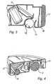
Fig. 1 is a perspective cut-away view of a robotic vacuum cleaner according to an embodiment of the invention; -
Fig. 2 is a perspective view of the robotic vacuum cleaner according to the embodiment of the invention; -
Fig. 3 is a sectional view of the rear half of the robotic vacuum cleaner according to the embodiment of the invention; -
Fig. 4 is a perspective sectional view of the left half of the robotic vacuum cleaner according to the embodiment of the invention; -
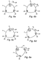
Fig. 5 is a schematic top view of turning circles of the robotic vacuum cleaner according to the embodiment of the invention; -
Fig. 6a - 6e are a top view sequence showing the operation of the robotic vacuum cleaner according to the embodiment of the invention when moving to avoid an obstacle which has been detected on the right side. -
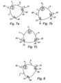
Fig. 7a - 7c are a top view sequence showing the operation of the robotic vacuum cleaner according to the embodiment of the invention when moving to pass between two obstacles which have been detected on the right side and the left side respectively. -
Fig. 8 is top view showing the situation where the robotic vacuum cleaner according to the embodiment of the invention will not fit between two obstacles which have been detected on the right side and on the left side respectively. - In
Figs. 1 - 4 , a robotic cleaning device according to the invention in the form of a robotic vacuum cleaner is shown. The vacuum cleaner comprises a main body in the form of a housing. The main body has a general overall shape of an equilateral triangular block having afront end portion 3, a leftrear end portion 4 and a rightrear end portion 5. These threeend portions left side wall 7 extends from thefront end portion 3 to the leftrear end portion 4, and aright side wall 6 extends from thefront end portion 3 to the rightrear end portion 5. The left and theright side walls rear end portion 4 to the rightrear end portion 5 via thefront end portion 3. The bumper is a flexibly mounted part of the main body. Finally, arear side wall 17 extends from the leftrear end portion 4 to the rightrear end portion 5. - The bumper cooperates with
several sensors 21. Thesensors 21 register when the bumper is pushed, which occurs when the robotic vacuum cleaner runs into an obstacle. Thus, the bumper and thesensors 21 function as obstacle detecting means. - The main body accommodates a controllable drive means including a
steerable drive wheel 2 mounted in thefront end portion 3. Thedrive wheel 2 is rotatable round awheel shaft 9 and is brought to rotate round thewheel shaft 9 by an electric drive motor 8 for driving the robotic vacuum cleaner. Thewheel shaft 9 and the drive motor 8 are fixed to afirst ring member 10, which is rotatably mounted on a second,stationary ring member 11. Thefirst ring member 10 is able to rotate round a central vertical axis while gliding on the secondstationary ring member 11. Thefirst ring member 10 is provided with anexternal toothed ring 12. Anelectric steering motor 13 is connected to thetoothed ring 12 for rotating thefirst ring member 10. Thus, when thesteering motor 13 is operated to rotate thefirst ring member 10, thesteerable drive wheel 2 is brought to pivot round a vertical axis, whereby the driving direction is changed and the vacuum cleaner turns. - For powering the electric drive motor 8 and the
electric steering motor 13, a set ofchargeable batteries 14 is provided in the main body. - The robotic vacuum cleaner further includes cleaning means in the form of vacuum means. The vacuum means includes a
suction fan 15 sucking dust and debris from a surface to be cleaned through asuction slit 16. The suction slit extends substantially over the whole breadth of the vacuum cleaner at the widest part thereof, i.e. at the rear part. The suction slit 16 is connected to adustbin 18 by a passage. In the passage at the suction slit 16 arotatable brush roll 19 is fitted to enhance the dust and debris collecting properties of the vacuum cleaner. The passage with the entrance to thedustbin 18 and thebrush roll 19 extends over substantially the whole length of the suction slit 16. Thereby collected dust and debris need not be transported in a sideway direction in the vacuum cleaner, and need only be lifted a small height in order to get into thedustbin 18. Thus, the energy needed for collecting dust and debris is kept at a low level. This contributes to the low energy consumption of the vacuum cleaner according to the invention and extends the battery time. - Finally, the vacuum means include a filter protecting the
suction fan 15 from any collected dust or debris in thedustbin 18. - A control means in the form of a
micro processor 20 is operatively connected to the drive motor 8, thesteering motor 13 and thesensors 21. - Finally, the robotic vacuum cleaner is provided with support means in the form of fixed
non-pivotable support wheels 26, cf.Fig. 6 - 8 . - In
Fig. 5 , the turning properties of the robotic vacuum cleaner according to the invention are illustrated. A main left-turn axis 23 is located in the leftrear end portion 4, and a main right-turn axis 24 is located in the rightrear end portion 5. Theleft side wall 7 is shaped as circular arc having a centre of curvature that coincides with the main right-turn axis 24, and theright side wall 6 is shaped as a circular arc having a centre of curvature that coincides with the main left-turn axis 23. - With reference to
fig. 5 , in order to avoid anobstacle 25 located straight ahead of the robotic vacuum cleaner, the vacuum cleaner rotates round one of themain turn axis side wall obstacle 25. Consequently, no rear part of the main body will get stuck on theobstacle 25 during turning, and the vacuum cleaner will be able to move clear by only the turning motion without sliding. - With reference to
Fig. 6 - 8 , the operation of the vacuum cleaner according to the described embodiment of the invention will be described. - In
Fig. 6 a sequence illustrating the turning of the robotic vacuum cleaner when encountering theobstacle 25 on the right side is shown. InFig. 6a , the vacuum cleaner is travelling in a straight forward direction. When the detecting means in form of the bumper and thesensors 21 register the hit, the presence of theobstacle 25 on the right side of the main body is communicated to the control means 20. Then the control means activates thesteering motor 13, which will rotate thefirst ring member 10 such that thesteerable driving wheel 2 is pivoted. Thereby the driving direction of thesteerable driving wheel 2 is turned approximately 45° to the left, cf.Fig. 6c . This new driving direction is perpendicular to a line taken from the centre of thedrive wheel 2 and the main left-turn axis 23. Consequently, the robotic vacuum cleaner will begin to turn left round the main left-turn axis 23. - Due to the combination of the circular arc-shaped
side wall 6 and the location of the main left-turn axis 23, the vacuum cleaner will move clear from the obstacle by this turning motion only, cf.Fig. 6d . As shown inFig. 6e , the vacuum cleaner is completely free from theobstacle 25 after having performed a turn of approximately 60°. Thereafter the control means 20 can activate thesteering motor 13 to pivot thesteerable drive wheel 2 back to the forward driving position, or select any other suitable driving direction. During this obstacle avoiding turn, thedriving wheel 2 has continuously turned with constant rotational speed and thus maintained the speed of the vacuum cleaner. Furthermore, due to the concentration of heavy components, such asbatteries 14, driving andsteering motors 8, 13 andsuction fan 15, to the front end of the main body, the vacuum cleaner benefits from the momentum forces from these components during the turn round the main left-turn axis 23. - In
Fig. 7 a sequence illustrating the turning of the robotic vacuum cleaner when encountering anobstacle second obstacle 25' on the left side when turning left to avoid afirst obstacle 25 on the right side, the control means is activated to turn thedrive wheel 2 to rotate approximately 90° from the position inFig. 6d . Therein, thedrive wheel 2 obtains a new driving direction, which is directed approximately 45 ° to the right of the forward driving direction. This new driving direction is perpendicular to a line taken from the centre of thedrive wheel 2 and the main right-turn axis 24. Consequently, the robotic vacuum cleaner will begin to turn right round the main right-turn axis 24. - Due to the combination of the circular arc-shaped
side walls obstacles turn axis 23 and then a right turn around the mainright turn axis 24. Each turn extends over angles of approximately 60°. InFig. 7c , the vacuum cleaner is shown in a position between theobstacles steering motor 13 to pivot thesteerable drive wheel 2 back to the forward driving position, and the vacuum cleaner will continue the cleaning operation. - Should the distance between two
obstacles Fig. 8 , theright side wall 6 will hit thefirst obstacle 25 again when the vacuum cleaner starts to turn right around the main right-turn axis 24 in order to turn away from thesecond obstacle 25'. Thereby the control means 20 will know that the vacuum cleaner can not pass between theobstacles tight obstacles
Claims (16)
- A robotic cleaning device, comprising
a main body, which accommodates
controllable drive means (2, 8) arranged to move the device over a surface,
cleaning means (15, 16) arranged to clean the surface when the device is moved over the surface,
obstacle detecting means (21), and
control means (20) connected to the drive means and the obstacle detecting means, wherein
the main body has a left side wall (7) connecting a front end portion (3) with a left rear end portion (4), and a right side wall (6) connecting the front end portion with a right rear end portion (5), wherein a rear side wall (17) connects the right rear end portion with the left rear end portion; characterised in that
the control means, when receiving information from the obstacle detecting means about a detected obstacle, is arranged to control the drive means to rotate the device around one of a main left-turn axis (23) located at the left rear end portion and a main right-turn axis (24) located at the right rear end portion, such that the device performs substantially only turning motion round the one of said axes; and wherein
the left side wall and the right side wall are configured such that the device is moved clear of the detected obstacle by said turning motion. - The robotic cleaning device according to claim 1, wherein the left side wall and the right side wall are substantially isosceles sides having a vertex at the front end portion.
- The robotic cleaning device according to claim 1 or 2, wherein the left side wall and the right side wall are convex.
- The robotic cleaning device according to any of claims 1-3, wherein at least a major portion of the left side wall is shaped as a circular arc having a centre of curvature that coincides with the main right-turn axis, and a major portion of the right side wall is shaped as a circular arc having a centre of curvature that coincides with the main left-turn axis.
- The robotic cleaning device according to any of claims 1 - 4, wherein the left side wall and the right side wall include a flexible bumper and/or a flexibly mounted bumper.
- The robotic cleaning device according to any of claims 1 - 5, wherein the rear side wall is convex.
- The robotic cleaning device according to claim 6, wherein at least a major portion of the rear side wall is shaped as a circular arc having a centre of curvature located in the front end portion.
- The robotic cleaning device according to any of claims 1 - 7, wherein the main body has a general overall shape of a triangular block, preferably an equilateral triangular block.
- The robotic cleaning device according to any of claims 1 - 8, wherein the drive means includes a steerable drive wheel (2), and wherein the control means is arranged to control the drive means by steering the steerable drive wheel.
- The robotic cleaning device according to claim 9, wherein the steerable drive wheel is mounted in front of an axis between the main left-turn axis and the main right-turn axis, preferably at the front end portion.
- The robotic cleaning device according to claim 10, wherein at least a major portion, preferable more than 80%, of the weight of the device is carried by the steering wheel.
- The robotic cleaning device according to any of claims 1 - 11, wherein the drive means includes support means (26) having low friction in a main forward driving direction, and high friction in both directions of an axis perpendicular to the main forward driving direction; such that all turning axes of the main body, when performing only turning motion, are located on that axis.
- The robotic cleaning device according to claim 12, wherein the support means include a non-pivotable support wheel (26).
- The robotic cleaning device according to claim 13, wherein the support means include two non-pivotable support wheels mounted in the left rear end portion and in the right rear end portion, respectively.
- The robotic cleaning device according to any of claims 1 - 14, wherein the cleaning means comprises vacuum cleaning means (15, 16).
- The robotic cleaning device according to claim 15, wherein the vacuum means includes a suction slit (16) which extends from the left rear end portion to the right rear end portion over substantially the whole breadth of the main body.
Applications Claiming Priority (2)
| Application Number | Priority Date | Filing Date | Title |
|---|---|---|---|
| SE0501613 | 2005-07-08 | ||
| PCT/SE2006/000847 WO2007008148A1 (en) | 2005-07-08 | 2006-07-06 | Robotic cleaning device |
Publications (3)
| Publication Number | Publication Date |
|---|---|
| EP1906807A1 EP1906807A1 (en) | 2008-04-09 |
| EP1906807A4 EP1906807A4 (en) | 2011-03-09 |
| EP1906807B1 true EP1906807B1 (en) | 2012-01-25 |
Family
ID=37637410
Family Applications (1)
| Application Number | Title | Priority Date | Filing Date |
|---|---|---|---|
| EP06747992A Active EP1906807B1 (en) | 2005-07-08 | 2006-07-06 | Robotic cleaning device |
Country Status (7)
| Country | Link |
|---|---|
| US (1) | US8032978B2 (en) |
| EP (1) | EP1906807B1 (en) |
| JP (1) | JP5048663B2 (en) |
| KR (1) | KR101322970B1 (en) |
| CN (1) | CN100586356C (en) |
| AT (1) | ATE542459T1 (en) |
| WO (1) | WO2007008148A1 (en) |
Families Citing this family (59)
| Publication number | Priority date | Publication date | Assignee | Title |
|---|---|---|---|---|
| CN101816533B (en) * | 2009-02-27 | 2012-08-01 | 和硕联合科技股份有限公司 | Adjustable dust collecting box and dust absorption device thereof |
| JP5037549B2 (en) * | 2009-03-10 | 2012-09-26 | 東芝テック株式会社 | Autonomous mobile device |
| DE102009049637A1 (en) * | 2009-10-15 | 2011-04-28 | Carl Freudenberg Kg | Cleaning robot for cleaning e.g. narrow points of room, has cleaning cloth flexibly formed in area in which cloth outwardly protrudes from guiding surface, and housing formed as regular polygon or hexagon |
| DE102010045096A1 (en) * | 2010-09-13 | 2012-03-15 | Carl Freudenberg Kg | Drive system for a cleaning device and cleaning device |
| JP5832553B2 (en) * | 2010-12-30 | 2015-12-16 | アイロボット コーポレイション | Coverage robot navigation |
| PL394570A1 (en) | 2011-04-15 | 2012-10-22 | Robotics Inventions Spólka Z Ograniczona Odpowiedzialnoscia | Robot for raised floors and method for raised floor maintenance |
| KR101566207B1 (en) * | 2011-06-28 | 2015-11-13 | 삼성전자 주식회사 | Robot cleaner and control method thereof |
| US8930493B2 (en) | 2012-03-20 | 2015-01-06 | International Business Machines Corporation | Inter-domain replication of service information |
| JP6068823B2 (en) * | 2012-04-27 | 2017-01-25 | シャープ株式会社 | Self-propelled vacuum cleaner |
| JP2013231536A (en) * | 2012-04-27 | 2013-11-14 | Sharp Corp | Self-propelled air cleaner |
| JP6071251B2 (en) * | 2012-05-30 | 2017-02-01 | 三菱電機株式会社 | Self-propelled vacuum cleaner |
| DE102012107765B4 (en) * | 2012-08-23 | 2020-02-13 | Miele & Cie. Kg | Robotic vacuum and method for operating a robotic vacuum |
| KR102142162B1 (en) | 2012-08-27 | 2020-09-14 | 에이비 엘렉트로룩스 | Robot positioning system |
| US9615714B2 (en) * | 2012-11-09 | 2017-04-11 | Samsung Electronics Co., Ltd. | Autonomous cleaning device |
| US10111563B2 (en) | 2013-01-18 | 2018-10-30 | Sunpower Corporation | Mechanism for cleaning solar collector surfaces |
| US9675222B2 (en) * | 2013-03-28 | 2017-06-13 | Yujin Robot Co., Ltd. | Cleaning robot having expanded cleaning territory |
| WO2014169943A1 (en) * | 2013-04-15 | 2014-10-23 | Aktiebolaget Electrolux | Robotic vacuum cleaner |
| CN105101855A (en) * | 2013-04-15 | 2015-11-25 | 伊莱克斯公司 | Robotic vacuum cleaner with protruding sidebrush |
| CN203987872U (en) | 2013-06-03 | 2014-12-10 | 碧洁家庭护理有限公司 | Autonomous type floor cleaning equipment |
| USD744705S1 (en) * | 2013-10-24 | 2015-12-01 | Aktiebolaget Electrolux | Vacuum cleaner |
| US11235893B2 (en) | 2013-12-05 | 2022-02-01 | The Boeing Company | End effector for cleaning objects having multiple surfaces |
| KR102393550B1 (en) * | 2013-12-19 | 2022-05-04 | 에이비 엘렉트로룩스 | Prioritizing cleaning areas |
| KR102099495B1 (en) | 2013-12-19 | 2020-04-09 | 에이비 엘렉트로룩스 | Sensing climb of obstacle of a robotic cleaning device |
| EP3082544B1 (en) * | 2013-12-19 | 2020-10-07 | Aktiebolaget Electrolux | Robotic vacuum cleaner with side brush moving in spiral pattern |
| WO2015090397A1 (en) | 2013-12-19 | 2015-06-25 | Aktiebolaget Electrolux | Robotic cleaning device |
| CN105744872B (en) | 2013-12-19 | 2020-01-14 | 伊莱克斯公司 | Adaptive speed control of rotating side brushes |
| EP3082537B1 (en) | 2013-12-19 | 2020-11-18 | Aktiebolaget Electrolux | Robotic cleaning device and method for landmark recognition |
| KR102124235B1 (en) | 2013-12-19 | 2020-06-24 | 에이비 엘렉트로룩스 | Robotic cleaning device with perimeter recording function |
| US20160302637A1 (en) * | 2013-12-20 | 2016-10-20 | Aktiebolaget Electrolux | Autononmous cleaner |
| EP3082539B1 (en) | 2013-12-20 | 2019-02-20 | Aktiebolaget Electrolux | Dust container |
| CN104000541B (en) * | 2014-06-16 | 2016-05-04 | 成都北斗群星智能科技有限公司 | Support sweeping robot and threshold detection method that threshold detects |
| WO2016002186A1 (en) * | 2014-06-30 | 2016-01-07 | パナソニックIpマネジメント株式会社 | Autonomous travel-type cleaner |
| EP3167341B1 (en) | 2014-07-10 | 2018-05-09 | Aktiebolaget Electrolux | Method for detecting a measurement error in a robotic cleaning device |
| JP6459098B2 (en) * | 2014-09-08 | 2019-01-30 | アクチエボラゲット エレクトロルックス | Robot vacuum cleaner |
| WO2016037635A1 (en) | 2014-09-08 | 2016-03-17 | Aktiebolaget Electrolux | Robotic vacuum cleaner |
| WO2016056226A1 (en) * | 2014-10-10 | 2016-04-14 | パナソニックIpマネジメント株式会社 | Autonomous travel-type cleaner |
| JP2017213009A (en) | 2014-10-10 | 2017-12-07 | パナソニックIpマネジメント株式会社 | Autonomous travel type cleaner |
| JP1531010S (en) * | 2014-10-22 | 2015-08-17 | ||
| CN208085470U (en) * | 2014-11-04 | 2018-11-13 | 法国传动装置公司 | The wheeled vehicle automatically moved |
| EP3230814B1 (en) | 2014-12-10 | 2021-02-17 | Aktiebolaget Electrolux | Using laser sensor for floor type detection |
| WO2016091320A1 (en) | 2014-12-12 | 2016-06-16 | Aktiebolaget Electrolux | Side brush and robotic cleaner |
| EP3234713B1 (en) | 2014-12-16 | 2022-06-15 | Aktiebolaget Electrolux | Cleaning method for a robotic cleaning device |
| EP3234714B1 (en) | 2014-12-16 | 2021-05-12 | Aktiebolaget Electrolux | Experience-based roadmap for a robotic cleaning device |
| CN107405034B (en) | 2015-04-17 | 2022-09-13 | 伊莱克斯公司 | Robot cleaning apparatus and method of controlling the same |
| JP6476077B2 (en) * | 2015-06-18 | 2019-02-27 | シャープ株式会社 | Self-propelled electronic device and traveling method of the self-propelled electronic device |
| CN107920709A (en) | 2015-09-03 | 2018-04-17 | 伊莱克斯公司 | Robotic cleaning device system |
| US9582001B1 (en) * | 2015-10-07 | 2017-02-28 | X Development Llc | Motor system for vehicle steering and locomotion |
| CN106913290B (en) * | 2015-12-25 | 2020-09-25 | 北京奇虎科技有限公司 | Sweeper and control method based on sweeper |
| TWI680739B (en) * | 2016-02-05 | 2020-01-01 | 金寶電子工業股份有限公司 | Protection device of self-propelled vehicle |
| JP7035300B2 (en) | 2016-03-15 | 2022-03-15 | アクチエボラゲット エレクトロルックス | Robot Cleaning Devices, Methods for Performing Escarpment Detection in Robot Cleaning Devices, Computer Programs, and Computer Program Products |
| EP3454707B1 (en) | 2016-05-11 | 2020-07-08 | Aktiebolaget Electrolux | Robotic cleaning device |
| US20180329409A1 (en) * | 2017-05-11 | 2018-11-15 | Bot3, Inc. | Portable mobile robot and operation thereof |
| KR20220025250A (en) | 2017-06-02 | 2022-03-03 | 에이비 엘렉트로룩스 | Method of detecting a difference in level of a surface in front of a robotic cleaning device |
| JP6989210B2 (en) | 2017-09-26 | 2022-01-05 | アクチエボラゲット エレクトロルックス | Controlling the movement of robot cleaning devices |
| CN109808789A (en) * | 2017-11-21 | 2019-05-28 | 富泰华工业(深圳)有限公司 | Wheeled mobile robot it is anti-walk deflection device |
| CN108523774B (en) * | 2018-05-11 | 2020-08-28 | 安徽大江服装服饰有限公司 | Wall-touching type spraying device for floor sweeping robot |
| US10888204B2 (en) | 2019-05-29 | 2021-01-12 | Maniff Creations, Inc. | Removable cover for a robotic cleaning device |
| USD924508S1 (en) * | 2019-05-30 | 2021-07-06 | Trifo, Inc. | Home robot |
| EP4231887A1 (en) * | 2020-10-23 | 2023-08-30 | SharkNinja Operating LLC | Robotic cleaner |
Family Cites Families (28)
| Publication number | Priority date | Publication date | Assignee | Title |
|---|---|---|---|---|
| JPS62120510A (en) * | 1985-11-21 | 1987-06-01 | Hitachi Ltd | Control method for automatic cleaner |
| FR2620070A2 (en) * | 1986-12-11 | 1989-03-10 | Jonas Andre | AUTOBULATED MOBILE UNIT AND CLEANING APPARATUS SUCH AS A VACUUM COMPRISING SUCH A UNIT |
| JPH0786767B2 (en) * | 1987-03-30 | 1995-09-20 | 株式会社日立製作所 | Travel control method for self-propelled robot |
| JPH03166074A (en) * | 1989-11-27 | 1991-07-18 | Sony Corp | Self advancing robot |
| US5023444A (en) * | 1989-12-28 | 1991-06-11 | Aktiebolaget Electrolux | Machine proximity sensor |
| US5307273A (en) * | 1990-08-29 | 1994-04-26 | Goldstar Co., Ltd. | Apparatus and method for recognizing carpets and stairs by cleaning robot |
| KR930000081B1 (en) * | 1990-12-07 | 1993-01-08 | 주식회사 금성사 | Cleansing method of electric vacuum cleaner |
| JP3282206B2 (en) * | 1992-01-14 | 2002-05-13 | 松下電器産業株式会社 | Obstacle detection device for mobile work robot |
| KR940004375B1 (en) * | 1992-03-25 | 1994-05-23 | 삼성전자 주식회사 | Drive system for automatic vacuum cleaner |
| JPH06144215A (en) * | 1992-10-30 | 1994-05-24 | Meidensha Corp | Unmanned carriage |
| JPH06179145A (en) * | 1992-12-10 | 1994-06-28 | Toyoda Mach Works Ltd | Conveying truck |
| KR0140499B1 (en) * | 1993-08-07 | 1998-07-01 | 김광호 | Vacuum cleaner and control method |
| SE502834C2 (en) * | 1994-03-29 | 1996-01-29 | Electrolux Ab | Method and apparatus for detecting obstacles in self-propelled apparatus |
| SE514791C2 (en) * | 1994-06-06 | 2001-04-23 | Electrolux Ab | Improved method for locating lighthouses in self-propelled equipment |
| JPH08326025A (en) * | 1995-05-31 | 1996-12-10 | Tokico Ltd | Cleaning robot |
| JPH09150741A (en) * | 1995-11-29 | 1997-06-10 | Toyota Auto Body Co Ltd | Electric truck for transporting heavy cargo |
| SE506372C2 (en) * | 1996-04-30 | 1997-12-08 | Electrolux Ab | Self-propelled device |
| US5935179A (en) * | 1996-04-30 | 1999-08-10 | Aktiebolaget Electrolux | System and device for a self orienting device |
| US6226830B1 (en) * | 1997-08-20 | 2001-05-08 | Philips Electronics North America Corp. | Vacuum cleaner with obstacle avoidance |
| SE510524C2 (en) * | 1997-09-19 | 1999-05-31 | Electrolux Ab | Electronic demarcation system |
| SE511254C2 (en) * | 1998-01-08 | 1999-09-06 | Electrolux Ab | Electronic search system for work tools |
| US7155308B2 (en) * | 2000-01-24 | 2006-12-26 | Irobot Corporation | Robot obstacle detection system |
| JP2003280740A (en) * | 2002-03-25 | 2003-10-02 | Matsushita Electric Ind Co Ltd | Movable device |
| EP1547361B1 (en) * | 2002-09-13 | 2016-04-06 | iRobot Corporation | A navigational control system for a robotic device |
| KR100492588B1 (en) * | 2003-01-23 | 2005-06-03 | 엘지전자 주식회사 | Position information recognition apparatus for automatic running vacuum cleaner |
| AU2004202834B2 (en) * | 2003-07-24 | 2006-02-23 | Samsung Gwangju Electronics Co., Ltd. | Robot Cleaner |
| US20060200281A1 (en) * | 2005-02-18 | 2006-09-07 | Andrew Ziegler | Autonomous surface cleaning robot for wet and dry cleaning |
| ATE523130T1 (en) * | 2005-02-18 | 2011-09-15 | Irobot Corp | SELF-DRIVEN SURFACE CLEANING ROBOT FOR WET AND DRY CLEANING |
-
2006
- 2006-07-06 US US11/995,071 patent/US8032978B2/en not_active Expired - Fee Related
- 2006-07-06 CN CN200680024913A patent/CN100586356C/en active Active
- 2006-07-06 KR KR1020087002671A patent/KR101322970B1/en active IP Right Grant
- 2006-07-06 JP JP2008520218A patent/JP5048663B2/en active Active
- 2006-07-06 EP EP06747992A patent/EP1906807B1/en active Active
- 2006-07-06 WO PCT/SE2006/000847 patent/WO2007008148A1/en active Application Filing
- 2006-07-06 AT AT06747992T patent/ATE542459T1/en active
Also Published As
| Publication number | Publication date |
|---|---|
| EP1906807A1 (en) | 2008-04-09 |
| KR20080028988A (en) | 2008-04-02 |
| WO2007008148A1 (en) | 2007-01-18 |
| US20090126143A1 (en) | 2009-05-21 |
| US8032978B2 (en) | 2011-10-11 |
| CN101217907A (en) | 2008-07-09 |
| EP1906807A4 (en) | 2011-03-09 |
| ATE542459T1 (en) | 2012-02-15 |
| CN100586356C (en) | 2010-02-03 |
| JP5048663B2 (en) | 2012-10-17 |
| JP2009500741A (en) | 2009-01-08 |
| KR101322970B1 (en) | 2013-10-29 |
Similar Documents
| Publication | Publication Date | Title |
|---|---|---|
| EP1906807B1 (en) | Robotic cleaning device | |
| JP6706770B2 (en) | Autonomous traveling vacuum cleaner | |
| US11014460B2 (en) | Compact autonomous coverage robot | |
| CN107422723B (en) | Overlay robot navigation | |
| US6601265B1 (en) | Vacuum cleaner | |
| KR101613106B1 (en) | Drive arrangement for a mobile robot | |
| KR101613107B1 (en) | Autonomous surface treating appliance | |
| KR101892652B1 (en) | Electric cleaner | |
| JP2017213009A (en) | Autonomous travel type cleaner | |
| KR20150141980A (en) | Robotic vacuum cleaner | |
| KR20150141979A (en) | Robotic vacuum cleaner with protruding sidebrush | |
| KR102662324B1 (en) | robotic vacuum | |
| JP2020074918A (en) | Robotic dust collector |
Legal Events
| Date | Code | Title | Description |
|---|---|---|---|
| PUAI | Public reference made under article 153(3) epc to a published international application that has entered the european phase |
Free format text: ORIGINAL CODE: 0009012 |
|
| 17P | Request for examination filed |
Effective date: 20080208 |
|
| AK | Designated contracting states |
Kind code of ref document: A1 Designated state(s): AT BE BG CH CY CZ DE DK EE ES FI FR GB GR HU IE IS IT LI LT LU LV MC NL PL PT RO SE SI SK TR |
|
| A4 | Supplementary search report drawn up and despatched |
Effective date: 20110209 |
|
| GRAP | Despatch of communication of intention to grant a patent |
Free format text: ORIGINAL CODE: EPIDOSNIGR1 |
|
| DAX | Request for extension of the european patent (deleted) | ||
| GRAS | Grant fee paid |
Free format text: ORIGINAL CODE: EPIDOSNIGR3 |
|
| GRAA | (expected) grant |
Free format text: ORIGINAL CODE: 0009210 |
|
| AK | Designated contracting states |
Kind code of ref document: B1 Designated state(s): AT BE BG CH CY CZ DE DK EE ES FI FR GB GR HU IE IS IT LI LT LU LV MC NL PL PT RO SE SI SK TR |
|
| REG | Reference to a national code |
Ref country code: GB Ref legal event code: FG4D |
|
| REG | Reference to a national code |
Ref country code: CH Ref legal event code: EP |
|
| REG | Reference to a national code |
Ref country code: AT Ref legal event code: REF Ref document number: 542459 Country of ref document: AT Kind code of ref document: T Effective date: 20120215 |
|
| REG | Reference to a national code |
Ref country code: IE Ref legal event code: FG4D |
|
| REG | Reference to a national code |
Ref country code: DE Ref legal event code: R096 Ref document number: 602006027316 Country of ref document: DE Effective date: 20120322 |
|
| REG | Reference to a national code |
Ref country code: NL Ref legal event code: VDEP Effective date: 20120125 |
|
| LTIE | Lt: invalidation of european patent or patent extension |
Effective date: 20120125 |
|
| PG25 | Lapsed in a contracting state [announced via postgrant information from national office to epo] |
Ref country code: BE Free format text: LAPSE BECAUSE OF FAILURE TO SUBMIT A TRANSLATION OF THE DESCRIPTION OR TO PAY THE FEE WITHIN THE PRESCRIBED TIME-LIMIT Effective date: 20120125 Ref country code: LT Free format text: LAPSE BECAUSE OF FAILURE TO SUBMIT A TRANSLATION OF THE DESCRIPTION OR TO PAY THE FEE WITHIN THE PRESCRIBED TIME-LIMIT Effective date: 20120125 Ref country code: NL Free format text: LAPSE BECAUSE OF FAILURE TO SUBMIT A TRANSLATION OF THE DESCRIPTION OR TO PAY THE FEE WITHIN THE PRESCRIBED TIME-LIMIT Effective date: 20120125 Ref country code: IS Free format text: LAPSE BECAUSE OF FAILURE TO SUBMIT A TRANSLATION OF THE DESCRIPTION OR TO PAY THE FEE WITHIN THE PRESCRIBED TIME-LIMIT Effective date: 20120525 Ref country code: BG Free format text: LAPSE BECAUSE OF FAILURE TO SUBMIT A TRANSLATION OF THE DESCRIPTION OR TO PAY THE FEE WITHIN THE PRESCRIBED TIME-LIMIT Effective date: 20120425 |
|
| PG25 | Lapsed in a contracting state [announced via postgrant information from national office to epo] |
Ref country code: FI Free format text: LAPSE BECAUSE OF FAILURE TO SUBMIT A TRANSLATION OF THE DESCRIPTION OR TO PAY THE FEE WITHIN THE PRESCRIBED TIME-LIMIT Effective date: 20120125 Ref country code: GR Free format text: LAPSE BECAUSE OF FAILURE TO SUBMIT A TRANSLATION OF THE DESCRIPTION OR TO PAY THE FEE WITHIN THE PRESCRIBED TIME-LIMIT Effective date: 20120426 Ref country code: PT Free format text: LAPSE BECAUSE OF FAILURE TO SUBMIT A TRANSLATION OF THE DESCRIPTION OR TO PAY THE FEE WITHIN THE PRESCRIBED TIME-LIMIT Effective date: 20120525 Ref country code: LV Free format text: LAPSE BECAUSE OF FAILURE TO SUBMIT A TRANSLATION OF THE DESCRIPTION OR TO PAY THE FEE WITHIN THE PRESCRIBED TIME-LIMIT Effective date: 20120125 Ref country code: PL Free format text: LAPSE BECAUSE OF FAILURE TO SUBMIT A TRANSLATION OF THE DESCRIPTION OR TO PAY THE FEE WITHIN THE PRESCRIBED TIME-LIMIT Effective date: 20120125 |
|
| REG | Reference to a national code |
Ref country code: AT Ref legal event code: MK05 Ref document number: 542459 Country of ref document: AT Kind code of ref document: T Effective date: 20120125 |
|
| PG25 | Lapsed in a contracting state [announced via postgrant information from national office to epo] |
Ref country code: CY Free format text: LAPSE BECAUSE OF FAILURE TO SUBMIT A TRANSLATION OF THE DESCRIPTION OR TO PAY THE FEE WITHIN THE PRESCRIBED TIME-LIMIT Effective date: 20120125 |
|
| PG25 | Lapsed in a contracting state [announced via postgrant information from national office to epo] |
Ref country code: EE Free format text: LAPSE BECAUSE OF FAILURE TO SUBMIT A TRANSLATION OF THE DESCRIPTION OR TO PAY THE FEE WITHIN THE PRESCRIBED TIME-LIMIT Effective date: 20120125 Ref country code: DK Free format text: LAPSE BECAUSE OF FAILURE TO SUBMIT A TRANSLATION OF THE DESCRIPTION OR TO PAY THE FEE WITHIN THE PRESCRIBED TIME-LIMIT Effective date: 20120125 Ref country code: SE Free format text: LAPSE BECAUSE OF FAILURE TO SUBMIT A TRANSLATION OF THE DESCRIPTION OR TO PAY THE FEE WITHIN THE PRESCRIBED TIME-LIMIT Effective date: 20120125 Ref country code: SI Free format text: LAPSE BECAUSE OF FAILURE TO SUBMIT A TRANSLATION OF THE DESCRIPTION OR TO PAY THE FEE WITHIN THE PRESCRIBED TIME-LIMIT Effective date: 20120125 Ref country code: CZ Free format text: LAPSE BECAUSE OF FAILURE TO SUBMIT A TRANSLATION OF THE DESCRIPTION OR TO PAY THE FEE WITHIN THE PRESCRIBED TIME-LIMIT Effective date: 20120125 Ref country code: RO Free format text: LAPSE BECAUSE OF FAILURE TO SUBMIT A TRANSLATION OF THE DESCRIPTION OR TO PAY THE FEE WITHIN THE PRESCRIBED TIME-LIMIT Effective date: 20120125 |
|
| PG25 | Lapsed in a contracting state [announced via postgrant information from national office to epo] |
Ref country code: SK Free format text: LAPSE BECAUSE OF FAILURE TO SUBMIT A TRANSLATION OF THE DESCRIPTION OR TO PAY THE FEE WITHIN THE PRESCRIBED TIME-LIMIT Effective date: 20120125 |
|
| PLBE | No opposition filed within time limit |
Free format text: ORIGINAL CODE: 0009261 |
|
| STAA | Information on the status of an ep patent application or granted ep patent |
Free format text: STATUS: NO OPPOSITION FILED WITHIN TIME LIMIT |
|
| 26N | No opposition filed |
Effective date: 20121026 |
|
| PG25 | Lapsed in a contracting state [announced via postgrant information from national office to epo] |
Ref country code: AT Free format text: LAPSE BECAUSE OF FAILURE TO SUBMIT A TRANSLATION OF THE DESCRIPTION OR TO PAY THE FEE WITHIN THE PRESCRIBED TIME-LIMIT Effective date: 20120125 |
|
| REG | Reference to a national code |
Ref country code: DE Ref legal event code: R097 Ref document number: 602006027316 Country of ref document: DE Effective date: 20121026 |
|
| PG25 | Lapsed in a contracting state [announced via postgrant information from national office to epo] |
Ref country code: MC Free format text: LAPSE BECAUSE OF NON-PAYMENT OF DUE FEES Effective date: 20120731 |
|
| REG | Reference to a national code |
Ref country code: CH Ref legal event code: PL |
|
| PG25 | Lapsed in a contracting state [announced via postgrant information from national office to epo] |
Ref country code: ES Free format text: LAPSE BECAUSE OF FAILURE TO SUBMIT A TRANSLATION OF THE DESCRIPTION OR TO PAY THE FEE WITHIN THE PRESCRIBED TIME-LIMIT Effective date: 20120506 Ref country code: CH Free format text: LAPSE BECAUSE OF NON-PAYMENT OF DUE FEES Effective date: 20120731 Ref country code: LI Free format text: LAPSE BECAUSE OF NON-PAYMENT OF DUE FEES Effective date: 20120731 |
|
| REG | Reference to a national code |
Ref country code: IE Ref legal event code: MM4A |
|
| PG25 | Lapsed in a contracting state [announced via postgrant information from national office to epo] |
Ref country code: IE Free format text: LAPSE BECAUSE OF NON-PAYMENT OF DUE FEES Effective date: 20120706 |
|
| PG25 | Lapsed in a contracting state [announced via postgrant information from national office to epo] |
Ref country code: TR Free format text: LAPSE BECAUSE OF FAILURE TO SUBMIT A TRANSLATION OF THE DESCRIPTION OR TO PAY THE FEE WITHIN THE PRESCRIBED TIME-LIMIT Effective date: 20120125 |
|
| PG25 | Lapsed in a contracting state [announced via postgrant information from national office to epo] |
Ref country code: LU Free format text: LAPSE BECAUSE OF NON-PAYMENT OF DUE FEES Effective date: 20120706 |
|
| PG25 | Lapsed in a contracting state [announced via postgrant information from national office to epo] |
Ref country code: HU Free format text: LAPSE BECAUSE OF FAILURE TO SUBMIT A TRANSLATION OF THE DESCRIPTION OR TO PAY THE FEE WITHIN THE PRESCRIBED TIME-LIMIT Effective date: 20060706 |
|
| REG | Reference to a national code |
Ref country code: FR Ref legal event code: PLFP Year of fee payment: 11 |
|
| REG | Reference to a national code |
Ref country code: FR Ref legal event code: PLFP Year of fee payment: 12 |
|
| REG | Reference to a national code |
Ref country code: FR Ref legal event code: PLFP Year of fee payment: 13 |
|
| PGFP | Annual fee paid to national office [announced via postgrant information from national office to epo] |
Ref country code: IT Payment date: 20220726 Year of fee payment: 17 Ref country code: GB Payment date: 20220720 Year of fee payment: 17 Ref country code: DE Payment date: 20220720 Year of fee payment: 17 |
|
| PGFP | Annual fee paid to national office [announced via postgrant information from national office to epo] |
Ref country code: FR Payment date: 20220720 Year of fee payment: 17 |
|
| P01 | Opt-out of the competence of the unified patent court (upc) registered |
Effective date: 20230521 |
|
| REG | Reference to a national code |
Ref country code: DE Ref legal event code: R119 Ref document number: 602006027316 Country of ref document: DE |
|
| GBPC | Gb: european patent ceased through non-payment of renewal fee |
Effective date: 20230706 |