JP5047459B2 - Light amount adjusting device, imaging optical unit, and imaging device - Google Patents
Light amount adjusting device, imaging optical unit, and imaging device Download PDFInfo
- Publication number
- JP5047459B2 JP5047459B2 JP2004366153A JP2004366153A JP5047459B2 JP 5047459 B2 JP5047459 B2 JP 5047459B2 JP 2004366153 A JP2004366153 A JP 2004366153A JP 2004366153 A JP2004366153 A JP 2004366153A JP 5047459 B2 JP5047459 B2 JP 5047459B2
- Authority
- JP
- Japan
- Prior art keywords
- adjusting device
- opening
- light
- imaging
- base member
- Prior art date
- Legal status (The legal status is an assumption and is not a legal conclusion. Google has not performed a legal analysis and makes no representation as to the accuracy of the status listed.)
- Active
Links
Images


Description
本発明は、デジタルカメラなどに用いられる光量調節装置に関し、例えば絞り動作を行う絞り羽根と露光動作を行うシャッタ羽根を備えた光量調節装置、この光量調節装置を備えた撮像光学ユニットおよびこの撮像光学ユニットを備えた撮像装置に関する。 The present invention relates to a light amount adjusting device used for a digital camera or the like, for example, a light amount adjusting device including an aperture blade that performs an aperture operation and a shutter blade that performs an exposure operation, an imaging optical unit including the light amount adjusting device, and the imaging optical The present invention relates to an imaging apparatus including a unit.
近年、デジタルカメラやカメラ付き携帯電話に用いられるカメラ用シャッタ装置や絞り装置などの光量調節装置は、デジタルカメラやカメラ付き携帯電話の小型化、薄型化に伴って、小型化、薄型化の要請が益々強まってきている。 In recent years, light quantity control devices such as camera shutter devices and diaphragm devices used in digital cameras and camera-equipped mobile phones are required to be smaller and thinner as digital cameras and camera-equipped mobile phones become smaller and thinner. Is getting stronger.
その中で、小型化を意図した従来の光量調節装置として、露出用の開口部を開閉するシャッタ羽根と開口部の絞りを行う絞り羽根とを別々備えた絞り兼用シャッタにおいて、露出開口を備えた地板に2枚の絞り羽根を所定距離相対的に移動可能に支持し、また、前記2枚の絞り羽根で形成される絞り開口を1枚のシャッタで開閉する構成を有すると共に、さらに2枚の絞り羽根を駆動する駆動源とシャッタを駆動する駆動源を別々に有し、これらの駆動源を所謂ムービングマグネットモータから構成しているものが提案されている(特許文献1)。 Among them, as a conventional light amount adjusting device intended for miniaturization, an aperture / shutter having a shutter blade that opens and closes an opening for exposure and a diaphragm blade that stops an aperture is provided with an exposure opening. The base plate is configured to support the two diaphragm blades so that they can move relative to each other by a predetermined distance, and has a configuration in which a diaphragm opening formed by the two diaphragm blades is opened and closed by a single shutter. A drive source that drives a diaphragm blade and a drive source that drives a shutter are separately provided, and these drive sources are configured by so-called moving magnet motors (Patent Document 1).
また、駆動源を上述の例とは別な形態とする光量調節装置として、露出開口を備えた地板に対し、2枚の開き用シャッタを所定の距離を相対的に移動可能に支持させると共に、該開き用シャッタに前記露出開口を介して対向する位置に2枚の閉じ用シャッタを所定の距離を相対的に移動可能に支持させ、該閉じ用シャッタ、および該開き用シャッタを駆動する駆動源を別々に持っている構成としたものが提案されている(特許文献2)。 In addition, as a light amount adjusting device in which the drive source is different from the above-described example, while supporting the two opening shutters so as to be relatively movable at a predetermined distance with respect to the ground plate provided with the exposure opening, A driving source for driving the closing shutter and the opening shutter by supporting two closing shutters at positions facing the opening shutter via the exposure opening so as to be relatively movable by a predetermined distance. Has been proposed (Patent Document 2).
これらの駆動源は、外周面を二分するように異なる磁極(N極及びS極)に着磁され、所定の角度範囲を回動するロータと、励磁用のコイルと、ロータの外周面に対向するように配置され、異なる磁極を発生し得る二つの磁極を有する二股状に形成された平板形状のヨークから構成されている。
上記した従来の光量調節装置において、ヨーク部材の位置精度のバラツキにより、一方の電磁アクチュエータの磁気が他方の電磁アクチュエータに作用し、例えば、前述したようにシャッタ羽根駆動用アクチュエータ及び絞り羽根駆動用アクチュエータの作動開始位置、及び所定距離回動した作動終了位置において、コイルへの通電を切ってもその位置を保持するようにヨークとロータ間に働く磁気吸引力が作用しているが、その磁気吸引力を弱めるような力が働き、作動開始位置、作動終了位置を維持できなくなる場合があり、個々のヨーク位置を後加工で調整することがあった。 In the conventional light quantity adjusting device described above, the magnetism of one electromagnetic actuator acts on the other electromagnetic actuator due to variations in the position accuracy of the yoke member. For example, as described above, the shutter blade driving actuator and the diaphragm blade driving actuator The magnetic attraction force acting between the yoke and the rotor is acting so as to maintain the position even when the coil is de-energized at the operation start position and the operation end position rotated by a predetermined distance. A force that weakens the force works, and it may become impossible to maintain the operation start position and the operation end position, and individual yoke positions may be adjusted by post-processing.
また、上記先行技術に開示された光量調節装置において、前者の光量調節装置は、駆動源として所謂ムービングマグネット方式のモータを使用しており、ロータとコイルの構造の関係上、どうしても背が高くならざるをうえなく、装置の薄型化には不向きである。 Further, in the light amount adjusting device disclosed in the above prior art, the former light amount adjusting device uses a so-called moving magnet type motor as a drive source, and the height is inevitably high due to the structure of the rotor and the coil. Inevitably, it is not suitable for thinning the device.
さらに、後者の光量調節装置の駆動源は、平板状のヨークを使用している関係上、ムービングマグネット方式のモータに比べて背が低くはなっているが、駆動源を載置している地板がモールドで形成されており、強度を保つ為には所定の厚みが必要となり、結果として装置の薄型化に限界があった。 Furthermore, the drive source of the latter light quantity adjusting device is shorter than a moving magnet type motor because of the use of a flat yoke, but the ground plate on which the drive source is placed Is formed by a mold, and a predetermined thickness is required to maintain the strength. As a result, there is a limit to thinning the apparatus.
本出願に係る発明は、このような従来の問題に鑑みなされたもので、複数のヨークなどから構成される複数の磁気回路に対し、磁気バランスが最適な位置に位置決めすることができる光量調節装置の提供を目的とする。 The invention according to the present application has been made in view of such a conventional problem, and is a light quantity adjusting device capable of positioning a magnetic balance at an optimal position with respect to a plurality of magnetic circuits including a plurality of yokes. The purpose is to provide.
また、上記した目的に加えて、装置全体の小型化、特に薄型化を図ることができ、さらに安価な光量調節装置の提供を目的とすることにある。 In addition to the above-described object, another object of the present invention is to provide a light quantity adjusting device that can reduce the size of the entire device, in particular, reduce the thickness, and that can be cheaper.
さらに、光量調節装置の厚みを薄くする事により、これらを含むレンズユニットを薄型化する撮像光学ユニット、およびデジタルカメラやカメラ付き携帯電話などの撮像装置の小型化、薄型化を図る撮像装置の提供を目的とすることにある。 Furthermore, by reducing the thickness of the light amount adjusting device, an imaging optical unit that reduces the thickness of the lens unit including them, and an imaging device that reduces the size and thickness of an imaging device such as a digital camera or a camera-equipped mobile phone are provided. The purpose is to.
本発明の目的を実現する光量調節装置は、請求項1に記載のように、撮像光が通過する開口が形成されたベース部材と、前記ベース部材の開口の光軸に平行な軸を中心に前記ベース部材に対して回転し、前記開口の光軸に直交する中心線の左右に配置して、前記開口を通過する撮像光の光量を制御する第1および第2の二つの遮光部材と、磁気回路により電磁的駆動力を得て前記二つの遮光部材をそれぞれ別々に駆動する二つの駆動手段と、を備え、コイルを巻回したボビンが挿入されて前記二つの駆動手段の前記磁気回路を構成する二つのヨークと、前記二つの遮光部材の一部が互いにどの位置でも重なるように前記第1の遮光部材の開き位置と閉じ位置を規定する一対の第1のストッパーおよび前記第2の遮光部材の開き位置と閉じ位置を規定する一対の第2のストッパと、を共通の板材により構成し、前記一対の第1のストッパーと前記一対の第2のストッパーとを前記開口の光軸に直交する中心線の上下方向に沿って配置し、かつ、該中心線に対して、前記一対の第1のストッパーを前記第1の遮光部材と同じ側に配置すると共に前記一対の第2のストッパーを前記第2の遮光部材と同じ側に配置したことを特徴とする。
A light amount adjusting device that realizes the object of the present invention is characterized in that, as described in
前記ベース部材には撮像光が通過する円形の開口が形成されており、前記共通の板材は該ベース部材の開口の光軸に直交する中心線の左右に略対象になるように設けられていることを特徴とする。 The base member is formed with a circular opening through which imaging light passes , and the common plate material is provided so as to be substantially the left and right of a center line orthogonal to the optical axis of the opening of the base member. It is characterized by that.
前記二つの駆動手段は、少なくとも周方向に2極に着磁されたマグネットを有し、該マグネットの円周方向に前記ヨークを配置したことを特徴とする。 The two driving means have a magnet magnetized in at least two poles in the circumferential direction, and the yoke is arranged in the circumferential direction of the magnet.
前記二つの遮光部材は、シャッタ部材同士の組み合わせ、絞り部材同士の組み合わせ、あるいはシャッタ部材と絞り部材との組み合わせであることを特徴とする。 The two light shielding members are a combination of shutter members, a combination of diaphragm members, or a combination of a shutter member and a diaphragm member.
本発明の目的を実現する撮像光学ユニットは、請求項5に記載のように、上記の光量調節装置と、前記光量調節装置の前方または後方に少なくともレンズを配置した撮像光学系とをユニット化し、前記ベース部材のヨークの少なくとも一部が、前記ヨークに最も近接する前記撮像光学系のレンズの外周より、光軸中心側に入り込んでいることを特徴とする。
An imaging optical unit that realizes the object of the present invention, as described in
本発明の目的を実現する撮像装置は、請求項6、7に記載のように、上記の光量調節装置と、前記光量調節装置の前方または後方に少なくともレンズを配置した撮像光学系とを備えた構成、あるいは上記の撮像光学ユニットを有した構成としたことを特徴とする。
Imaging apparatus for realizing the object of the present invention, as described in
本発明の光量調節装置によれば、複数の駆動手段ごとに複数のヨークを使用する場合に比べ部品の共用化、削減化が図れ、より安価な装置を提供できる。 According to the light amount adjusting device of the present invention, parts can be shared and reduced compared to the case where a plurality of yokes are used for each of a plurality of driving means, and a cheaper device can be provided.
また、従来はベース部材に複数の駆動手段を取り付けており、組み付け位置精度が狂うと複数の駆動手段間で磁気的な干渉が働き、駆動性能に影響が出る為、個々のヨーク位置を調整していたが、複数の駆動手段のヨークを共通の板材にて形成することにより組み込むので、位置精度は部品加工精度によるだけとなり、調整等の必要がない。 Conventionally, multiple drive means are attached to the base member. If the assembly position accuracy is incorrect, magnetic interference acts between the multiple drive means, affecting the drive performance. However, since the yokes of a plurality of driving means are incorporated by forming them with a common plate material, the positional accuracy depends only on the component processing accuracy, and there is no need for adjustment.
また、一つの部品で複数のシャッタ、絞り駆動用手段の磁気回路を構成することにより、一つの部品の加工精度により複数の駆動手段の位置決めができ、機械的にも磁気的にも駆動手段相互の位置を最適な位置に設定することができる。 In addition, by configuring a magnetic circuit for a plurality of shutters and diaphragm driving means with one component, positioning of a plurality of driving means can be performed with the machining accuracy of one component, and both driving means can be mechanically and magnetically connected. Can be set to an optimum position.
本発明による撮像光学ユニットによれば、上記した効果に加え、さらにヨークの一部を光量調節装置に最も近接するレンズの外周より光軸中心側に入りこませるように配置する事により、撮像光学ユニットの小型化、薄型化が図られる。 According to the imaging optical unit according to the present invention, in addition to the above-described effects, a part of the yoke is further arranged so as to enter the optical axis center side from the outer periphery of the lens closest to the light amount adjusting device. The unit can be made smaller and thinner.
本発明による撮像装置によれば、上記した効果に加え、さらに搭載する光量調節装置および撮像光学ユニットの薄型化により、撮像装置の薄型化および小型化を図ることができる。 According to the imaging apparatus of the present invention, in addition to the above-described effects, the imaging apparatus can be reduced in thickness and size by further reducing the thickness of the light amount adjusting device and the imaging optical unit to be mounted.
図1から図5は本発明の第一の実施例を示す。 1 to 5 show a first embodiment of the present invention.
図1は後述するカバー板を取り外した状態の光量調節装置の平面図であり、遮光部材としてシャッタ羽根と絞り羽根を有する。図1において、シャッタ羽根は閉状態、光線の光量を制限する絞り羽根は開状態を示している。図2は図1からシャッタ羽根と絞り羽根を取り除いた状態の平面図である。図3はシャッタ羽根と絞り羽根の両方が開いた状態を示し、図4はシャッタ羽根が開状態で絞り羽根が閉状態を示し、図5aはカバーをベース部材に取付けた状態を示す平面図、図5bは図5aのA-A線に沿った断面図である。 FIG. 1 is a plan view of a light amount adjusting device with a cover plate, which will be described later, removed, and has shutter blades and aperture blades as light shielding members. In FIG. 1, the shutter blades are in a closed state, and the diaphragm blades that limit the amount of light are in an open state. FIG. 2 is a plan view showing a state in which the shutter blades and the diaphragm blades are removed from FIG. 3 shows a state where both the shutter blades and the diaphragm blades are opened, FIG. 4 shows a state where the shutter blades are open and the diaphragm blades are closed, and FIG. 5a is a plan view showing a state where the cover is attached to the base member. FIG. 5b is a cross-sectional view taken along line AA in FIG. 5a.
本実施例は、図1から図5に示すように、撮影光(撮像光)が通過する円形の開口12がヨークを兼用するベース部材1に設けられる。ベース部材1は純鉄、電磁ステンレス、パーマロイ、ケイ素鋼板等の強磁性体の材料からなるヨーク用の材料からなる板材をプレス加工等により所定の形状に形成される。
In this embodiment, as shown in FIGS. 1 to 5, a
このベース部材1は、撮影光を通過する円形の開口2の光軸に直交する中心線L1を中心として図1、図2中、左右に略軸線対称に形成され、左部分に示す要素と同じ要素の右部分の符号は同じ数字とし、´を付して区別する。
This
ベース部材1には、磁極部1aと1bとが磁気的に略コの字形状をなすように形成されたヨークY、同様に磁極部1a´と1b´とが略コの字形状をなすように形成されたヨークY´を有している。対向する磁極部1aと1b間、及び磁極部1a´と1b´間の中心には、シャッタ羽根3、及び絞り羽根4を所定の角度回動駆動する周方向に2極に着磁されたロータ5、5´が所定間隙を介して回転可能にそれぞれ支持されている。左側のロータ5は前記ベース部材1に適当な方法で取り付けられる図5bに示す軸受け部材7上に形成された軸7aに回転可能に支持される。
The
更に、前記左右の各磁極部1b、1b´は、ロータ5、5´との対向する面積を増やすため、円弧状に切り曲げされ、ロータ5、5´の外周面の高さと同程度の幅で立ち上がっている。また、対向する各磁極部1a、1a´には、励磁するコイル8、8´が巻回されたボビン6、6´がそれぞれ挿入され、ボビン6、6´にはそれぞれ出力端子である端子9、9´が備えられている。
Further, each of the left and right
前記磁極部1a、1a´には、図5bに示すように、前記ロータ5との対向する面積を増やすため、ロータ5の外周面の高さと同程度の高さになるように磁極部1a、1a´と同形状で所定の厚さの平板1jがカシメ、接着等の適切な手段で固定されている。
As shown in FIG. 5b, the
シャッタ羽根3、絞り羽根4の回動支持構造
シャッタ羽根3、絞り羽根4の回動支持構造は以下のようになっている。前記シャッタ羽根3は、前記ベース部材1の下部に固定された軸受け部材7から突出するように形成された軸7bに前記シャッタ羽根3の穴3aが嵌合して回動中心をなすとともに、該軸7bは前記ベース部材1上に形成された穴1eを貫通し、前記ベース部材1上でシャッタ羽根3の穴3aと嵌合し、結果、前記シャッタ羽根3は所定の角度を回動可能に支持される。前記ベース部材1上には前記シャッタ羽根3の回動に対応して開き位置、閉じ位置を規定するストッパー1d、1cが切り曲げ等の方法で一体的に形成される。なお、軸7bおよび後述する軸7b´は、図1、図5a、図5bに示すように、開口2を通過する撮影光の光軸と平行である。
Rotation support structure of
前記絞り羽根4は、同様に前記ベース部材1の下部に固定された不図示の軸受け部材7´から突出するように形成された軸7b´に前記絞り羽根4の穴4aが嵌合し回動中心をなすとともに、該軸7b´は前記ベース部材1上に形成された穴1e´を貫通し、前記ベース部材1上で絞り羽根4の穴4a´と嵌合し、結果、前記絞り羽根4は所定の角度を回動可能に支持される。前記ベース部材1上には前記絞り羽根4の回動に対応して開き位置、閉じ位置を規定するストッパー1d´、1c´が切り曲げ等の方法で一体的に形成される。ここで、図1、図2に示すように、シャッタ羽根3の閉じ位置を規定するストッパー1cと開き位置を規定するストッパー1dとは中心線L1に沿った上下方向に配置され、同様に絞り羽根4の閉じ位置を規定するストッパー1c´と開き位置を規定するストッパー1d´とは中心線L1に沿った上下方向に配置されている。そして、左側に配置されるシャッタ羽根3のストッパー1c、1dは中心線L1に対してシャッタ羽根3と同じ左側に配置され、右側に配置される絞り羽根4のストッパー1c´、1d´は中心線L1に対して絞り羽根4と同じ右側に配置されている。
Similarly, the
前記シャッタ羽根3は、前述のように穴3aが軸7b上で回動可能に支持されるが、一方では、前記ロータ5と一体的に形成された駆動ピン5aが前記シャッタ羽根3に形成された長溝形状の長穴3bに遊嵌している。また、前記シャッタ羽根3の先端は前記開口2を覆うだけの面積を有している。シャッタ羽根3と絞り羽根4は、遮光性と潤滑性を有し、厚さ0.03〜0.15mmの熱可塑性プラスチックシートをプレス加工して形成される。
As described above, the
前記絞り羽根4は、前述のように穴4aが軸7b´上で回動可能に支持されるが、一方では、前記ロータ5´と一体的に形成された駆動ピン5a´が前記絞り羽根4に形成された長溝形状の長穴4b´に遊嵌している。また、前記絞り羽根4の先端には前記開口2より小さい小絞り用の開口4cが形成されている。
As described above, the
前記ベース部材1には、穴1g、1g´、1fが設けられている。穴1g、1g´はこの光量調節装置を不図示のカメラ本体に取り付けるためのものであり、位置決め穴1fはカバー部材10を取り付け固定するためのものである。
The
前記カバー部材10は、シャッタ羽根3、絞り羽根4の可動領域を覆い、シャッタ羽根3、絞り羽根4の浮き上がりを防止する。カバー部材10は金属ないしプラスチックの薄板からなり、ベース部材1上の位置きめ穴1fに適切な方法で固定され、下辺は図5aに示すごとくベース部材1に爪部10aが係合し、ベース部材1に対しカバー10の可撓性によりにより嵌め合い固定される。
The
次に、本実施例の光量調節装置の作動について説明する。 Next, the operation of the light amount adjusting device of this embodiment will be described.
まず、不図示のカメラのシャッタレリーズボタンが押される前は、図3のようにシャッタ羽根3及び絞り羽根4とも、それぞれの羽根は重なって開口部2から退避している。
First, before a shutter release button of a camera (not shown) is pressed, the
この状態において、シャッタ羽根駆動装置を構成する左側のシャッタ羽根用のロータ5は、図3に示すように、磁気吸引力により時計方向に回動しようとする力が働いており、シャッタ羽根3はストッパー1dにより係止され、開状態が維持されている。一方、絞り羽根駆動装置を構成する右側の絞り羽根用のロータ5´は、図3に示すように、磁気吸引力により反時計方向に回動しようとする力が働いており、絞り羽根4はストッパー1d´により係止され、開状態が維持されている。
In this state, as shown in FIG. 3, the left
次に、レリーズボタンが押されると、不図示の撮像素子はそれまで蓄積した電荷を放出し、その後所定露光量の電荷を蓄積した後、シャッタ羽根3を閉じて露光を終了し、その後蓄積した電荷の転送を行う。
Next, when the release button is pressed, the image sensor (not shown) releases the accumulated charge, accumulates a predetermined exposure amount, and then closes the
その時、不図示の駆動回路によりコイル8に通電されると、前記磁極部1a、1bはそれぞれN極、S極になり電磁的駆動力を受けるロータ5は反時計方向に回動し始める。ロータ5の反時計方向への回動に伴ってロータ5に一体的に設けられた駆動ピン5aも反時計方向に回動し始める。駆動ピン5aは回動に伴って前記シャッタ羽根3に形成された長溝3aの図4中右側の内壁部分を反時計方向に押圧し、シャッタ羽根3は軸7bを回動中心とし、時計方向に回動し開口2を閉鎖し、図1に示す状態に至る。
At that time, when the
シャッタ羽根3の閉鎖状態において、前記コイル8への通電を切ってもロータ5は磁気吸引力により反時計方向に回動しようとする力が働き、その力によりシャッタ羽根3も時計方向に回動しようとするが、ストッパー1cに係止され閉状態が維持される。
In the closed state of the
この時、前記シャッタ羽根3と絞り羽根4は全開状態から全閉状態までのどの位置でも必ず重なっており羽根同士が干渉することはない。
At this time, the
次に、撮像素子の電荷の転送が終了すると、シャッタ羽根3は再び開放する。このときシャッタ羽根用の駆動手段は、シャッタ閉鎖動作時と反対方向に駆動ピン5aを駆動する。その動作は今まで述べてきた、全開から全閉の動作と逆の動作を行い全開となる。
Next, when the charge transfer of the image sensor is completed, the
次に絞り羽根4の動作について説明する。
Next, the operation of the
不図示の露出制御機構により露光量が決まるとその時、不図示の駆動回路によりコイル8´に通電されると前記磁極部1a´、1b´はそれぞれS極、N極になりロータ5´は電磁的駆動力を受けて時計方向に回動し始める。ロータ5´の回動に伴ってロータ5´に一体的に設けられた駆動ピン5a´も時計方向に回動し始める。駆動ピン5a´は回動に伴って前記絞り羽根4に形成された長溝4b´の図4中左側の内壁部分を時計方向に押圧し、絞り羽根4は軸7b´を回動中心とし、反時計方向に回動し開口2を図4に示すように小絞り径4cに制限する。
When the exposure amount is determined by an exposure control mechanism (not shown), when the coil 8 'is energized by a drive circuit (not shown), the
閉鎖状態においては前記コイル8´への通電を切ってもロータ5´は磁気吸引力により時計方向に回動しようとする力が働き、その力により絞り羽根4も反時計方向に回動しようとするが、ストッパー1c´に係止され閉状態が維持される。
In the closed state, even if the coil 8 'is de-energized, the rotor 5' exerts a force to rotate clockwise by the magnetic attractive force, and the
この時、前記シャッタ羽根3と絞り羽根4は全開状態から全閉状態までのどの位置でも必ず重なっており羽根同士が干渉することはない。
At this time, the
また、本実施例の光量調節装置にあっては、図5bに示すように、ボビン6の厚みがカバー部材10を取付けた状態での光量調節装置の厚みと略同じに形成され、またボビン6の端子9は最外周位置に配置されているので、この端子9が多少厚み方向に突出していても、この端子9よりも内側部分ではこの光量調節装置の表裏面から厚み方向に突出するものがない。
Further, in the light amount adjusting device of this embodiment, as shown in FIG. 5B, the thickness of the
本実施例においては、ヨークを兼用したベース部材1に二つのアクチュエータを搭載し、一方をシャッタ羽根駆動用アクチュエータとして、他方を絞り羽根駆動用アクチュエータとする構成としたが、二つともシャッタ羽根駆動用アクチュエータとしても良い。このような構成をとればシャッタ羽根の開口を覆う面積を少なくすることができ、即ち一つにシャッタ羽根の移動距離を少なくすることができシャッタスピードが上がる。また、二つとも絞り羽根駆動用アクチュエータとしても良い、すなわち一方の絞り羽根には小絞り用開口を設け、他方の絞り羽根には中絞り用の開口を設け、所謂3段絞り装置とすることにより露出精度を上げることができる。
In this embodiment, two actuators are mounted on the
なお、本実施例において、複数のヨークY、Y´を共通の板材としてベース部材1を兼用しているが、この板材をベース部材1と別部材としても良い。また、図1、図2に示すように、前記共通の板材である複数のヨークY、Y´は撮影光を通過する円形の開口2の光軸に直交する中心線L1の左右に略軸線対称に設けられている。
In this embodiment, the
第二の実施例
図6および図7は第二の実施例を示す。
本第二の実施例は、光量調節装置として遮光部材である2枚のシャッタ羽根を備えたシャッタ装置としたもので、図6は第1のシャッタ羽根20および第2のシャッタ羽根21の待機状態を示しており、図7は第1のシャッタ羽根20および第2のシャッタ羽根21により開口2が閉鎖された状態を示している。基本的な構成として第一の実施例と異なる点は、第一の実施例における絞り羽根4に代えて第二のシャッタ羽根21を配置し、第1のシャッタ羽根20と第二のシャッタ羽根21には、開口2を囲むように切欠部20b、21bが形成されている点にあり、その他の部材は図1から図5に示した部材と同様であり、説明を省く。
Second Embodiment FIG. 6 and FIG. 7 shows the second embodiment.
The second embodiment is a shutter device having two shutter blades as a light shielding member as a light amount adjusting device. FIG. 6 shows a standby state of the
次に、この実施例のシャッタ装置の作動方法について説明する。 Next, an operation method of the shutter device of this embodiment will be described.
まず、不図示のカメラのシャッタレリーズボタンが押される前は、図6のように第1及び第2のシャッタ羽根20、21、それぞれの羽根の一部が重なって開口部2から退避し、各羽根20,21の切欠部20b、21bが開口2取り囲むように位置している。
First, before a shutter release button of a camera (not shown) is pressed, the first and
この状態において、第1のシャッタ羽根20の羽根駆動部分では、ロータ5は図6のように、磁気吸引力により時計方向に回動しようとする力が働いており、第1のシャッタ羽根20はストッパー1cにより係止され、開状態が維持されている。
In this state, in the blade driving portion of the
一方、第2のシャッタ羽根21の羽根駆動部分では、ロータ5´は図6のように、磁気吸引力により反時計方向に回動しようとする力が働いており、第1のシャッタ羽根21はストッパー1d´により係止され、開状態が維持されている。
On the other hand, in the blade driving portion of the
次に、レリーズボタンが押されると、撮像素子はそれまで蓄積した電荷を放出し、その後所定露光量の電荷を蓄積した後、シャッタ羽根群を閉じて露光を終了し、その後蓄積した電荷の転送を行う。 Next, when the release button is pressed, the image sensor releases the accumulated charge, and then accumulates a predetermined amount of exposure, then closes the shutter blade group to end the exposure, and then transfers the accumulated charge. I do.
その時、不図示の駆動回路によりコイル8に通電されると前記磁極部1a、1bはそれぞれS極、N極になりロータ5は時計方向に回動し始める。ロータ5の回動に伴ってロータ5に一体的に設けられた駆動ピン5aも時計方向に回動し始める。駆動ピン5aは回動に伴って前記第1のシャッタ羽根20に形成された長溝20aの図7中左側の内壁部分を時計方向に押圧し、第1のシャッタ羽根20は軸7bを回動中心とし、反時計方向に回動し開口2を閉鎖し、図7に示す状態に至る。
At that time, when the
一方、不図示の駆動回路によりコイル8への通電と同時にコイル8´に通電され、それとともに前記磁極部1a´、1b´はそれぞれS極、N極になりロータ5´は時計方向に回動し始める。ロータ5´の回動に伴ってロータ5に一体的に設けられた駆動ピン5a´も時計方向に回動し始める。駆動ピン5a´は回動に伴って前記第2のシャッタ羽根21に形成された長溝21aの図7中左側の内壁部分を時計方向に押圧し、第2のシャッタ羽根21は軸7bを回動中心とし、反時計方向に回動し開口2を閉鎖し、図7に示す状態に至る。
On the other hand, the coil 8 'is energized simultaneously with the energization of the
閉鎖状態において、前記コイル8への通電を切ってもロータ5は磁気吸引力により時計方向に回動しようとする力が働き、その力により第1のシャッタ羽根20も反時計方向に回動しようとするが、ストッパー1dに係止され閉状態が維持される。
In the closed state, even when the
また、同様に前記コイル8´への通電を切ってもロータ5´は磁気吸引力により反時計方向に回動しようとする力が働き、その力により第2のシャッタ羽根20も反時計方向に回動しようとするが、ストッパー1c´に係止され閉状態が維持される。
Similarly, even when the coil 8 'is de-energized, the rotor 5' exerts a force to rotate counterclockwise due to the magnetic attractive force, and the
この時、前記第1と第2のシャッタ羽根20,21は全開状態から全閉状態までのどの位置でも必ず重なっており、羽根同士が干渉することはない。
At this time, the first and
次に、撮像素子の電荷の転送が終了すると、第1と第2のシャッタ羽根20,21は再び開放する。その動作は今まで述べてきた、全開から全閉の動作と逆の動作を行い全開となる。
Next, when the charge transfer of the image sensor is completed, the first and
以上のように、本第一および第二の実施例においては、ヨークを兼用したベース1に二つの電磁アクチュエータを搭載し、第一の実施例では一方をシャッタ羽根駆動用アクチュエータとして、他方を絞り羽根駆動用アクチュエータとし、第二の実施例では両方をシャッタ羽根駆動用アクチュエータとし、複数(これらの実施例では2つ)の電磁アクチュエータの磁気回路をそれぞれ構成するヨークは共通のヨークとしてのベース部材1を使用する構成にした。
As described above, in the first and second embodiments, two electromagnetic actuators are mounted on the
このため、二つの電磁アクチュエータの位置精度は、1枚のベース部材1にプレス加工等により一体的に形成される共通ヨークの機械加工精度に依存することになり、従来の光量調節装置のように、ベース部材に取付けられるヨークの取付け位置精度のバラツキにより、一方の電磁アクチュエータの磁気が他方の電磁アクチュエータに作用し、例えば、前述したようにシャッタ羽根駆動用アクチュエータ及び絞り羽根駆動用アクチュエータの作動開始位置、あるいは所定距離回動した作動終了位置において、コイルへの通電を切ってもその位置を保持するようにヨークとロータ間に働くので磁気吸引力が作用しているが、その磁気吸引力を弱めるような力が働き、作動開始位置、作動終了位置を維持できなくなるといった弊害を防止できる。そして従来例では、個々のヨーク位置を後加工で調整していたが、本第一および第二の実施例においては、ヨークの絶対位置、相対位置が機械加工精度により決まるので、磁気回路上、磁気バランスが最適な位置に位置決めすることができた。
For this reason, the position accuracy of the two electromagnetic actuators depends on the machining accuracy of a common yoke integrally formed on one
また、第二の実施例に述べた第1のシャッタ羽根と第2のシャッタ羽根の代わりに二つとも絞り羽根駆動用アクチュエータとしても良い、すなわち第1のシャッタ羽根の代わりに小絞り用開口を持った第1の絞り羽根を設け、他方の第2のシャッタ羽根の代わりに中絞り用の開口を持った第2の絞り羽根を設け、所謂3段絞り装置とすることにより露出精度を上げることができる。
その構成、動作については第一実施例と同じであり、説明を省略する。
Further, instead of the first shutter blade and the second shutter blade described in the second embodiment, both may be used as diaphragm blade driving actuators, i.e., a small aperture opening is provided instead of the first shutter blade. A first diaphragm blade is provided, and a second diaphragm blade having a middle diaphragm opening is provided in place of the other second shutter blade, so that the exposure accuracy is improved by using a so-called three-stage diaphragm device. Can do.
The configuration and operation are the same as those in the first embodiment, and a description thereof will be omitted.
第三の実施例
次に本発明の第三の実施例を、図8によって説明する。
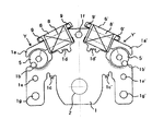
Third Embodiment Next, a third embodiment of the present invention will be described with reference to FIG.
本実施例は、前記第一または第二の実施例の光量調節装置を用いてレンズユニットとして構成したものである。したがって駆動部及び絞り羽根などの構成及び作動方法は同様である。 This embodiment is configured as a lens unit using the light amount adjusting device of the first or second embodiment. Therefore, the configuration and operation method of the drive unit and the diaphragm blades are the same.
図8に示すレンズユニットLUは、第一または第二の実施例に示す光量調節装置Eと、被写体側の前玉レンズ11と、結像面側の後玉レンズ12とを保持部材13を介して一体的に組付けて構成したもので、ヨークを構成する材料で形成されると共に、ヨークを一体的に形成したベース部材1(あるいはヨークを構成する部材にベース部材の機能を持たせたヨーク)における当該ヨークを、シャッタ羽根3に近接したレンズ11の外周より光軸中心側に一部オーバーラップさせており、これにより、レンズユニットLUの小型化を図っている。
A lens unit LU shown in FIG. 8 includes a light quantity adjusting device E shown in the first or second embodiment, a
これはヨークをベース部材と兼用させる事により、通常ならばベース部材の他にヨークの厚みが必要なため、近接するレンズに干渉してヨークとレンズをオーバーラップできないのに対して、本実施例ではベース部材の厚みのみでヨークの厚みを構成できるので、レンズに干渉することなくヨークを光軸中心側へオーバーラップして配置する事ができる。これにより、レンズユニットのサイズをより一層小型化することができる。 This is because the yoke is also used as a base member, and usually the thickness of the yoke is required in addition to the base member. Then, since the thickness of the yoke can be constituted only by the thickness of the base member, the yoke can be disposed so as to overlap the optical axis center side without interfering with the lens. Thereby, the size of the lens unit can be further reduced.
また、図8においては、ヨークが開口部2の周辺のベース部材を全て兼ねているが、ベース部材の一部分のみを兼ねるようにしても勿論良く、また、ヨーク部材より薄いベース部材上にヨーク部材を載置しても良い。
In FIG. 8, the yoke also serves as all the base members around the
また、図8においてはシャッタ及び絞り装置を備えた光量調節装置Eがレンズ群11、12の中に配置される、いわゆるビトゥインザレンズシャッタとなっており、ヨークを挟んで両側にレンズが配置されるビトゥインザレンズシャッタの場合が最もスペースの制約が多く、このため本実施例の効果が最も大きいが、レンズ群の被写体側最前部に配置される、いわゆるビフォアザレンズシャッタでも、レンズ群の最後尾に配置されるビハインドザレンズシャッタでも同様の効果は得られる。
In FIG. 8, a light amount adjusting device E having a shutter and a diaphragm device is a so-called between-the-lens shutter arranged in the
上述のように上記した第一、第二の実施例の光量調節装置は、上述したように、複数のヨークをベース部材上に一体的に形成して複数の磁気回路を構成しているので、各磁気回路同士の位置精度が格段に向上し、磁気回路同士が影響を及ぼし合うという不具合を解消できるという効果が得られる。またさらに、ヨーク部材の機能をベース部材に持たせることにより(あるいはベース部材の機能を薄くしたヨーク部材に持たせたと考えることもできる)、従来、所定の厚さのベース部材上に、シャッタ機構、または絞り機構を載置する構造に比べ、ベース部材を廃止し、その機能をシャッタ機構、または絞り機構を駆動する電磁装置に必然的に使用されるヨーク部材に持たせることにより薄型でより安価な光量調節装置を提供することができるという効果を有する。また、ベース部材1においてヨークY、Y´を構成する少なくとも一部は、ヨークに最も近接するレンズの外周より、光軸中心側に入り込んでいるように構成することにより、レンズユニットを小型化できるという効果を有している。
As described above, the light amount adjusting devices of the first and second embodiments as described above are configured by integrally forming a plurality of yokes on the base member to form a plurality of magnetic circuits. The positional accuracy between the magnetic circuits is remarkably improved, and it is possible to eliminate the problem that the magnetic circuits influence each other. Furthermore, by providing the base member with the function of the yoke member (or it can be considered that the yoke member with the thin base member function is provided), conventionally, a shutter mechanism is provided on the base member having a predetermined thickness. Compared to the structure where the diaphragm mechanism is mounted, the base member is abolished, and the function is provided to the shutter member or the yoke member that is inevitably used in the electromagnetic device that drives the diaphragm mechanism. A light amount adjusting device can be provided. Further, at least a part of the
第四の実施例
第一、第二の実施例の光量調節装置あるいは第三の実施例のレンズユニットを、図9および図10のようにデジタルカメラやカメラ付き携帯端末機器などの撮像装置に応用することにより、これら撮像装置の小型化、薄型化が達成できる。
Fourth Embodiment The light amount adjusting device of the first and second embodiments or the lens unit of the third embodiment is applied to an imaging device such as a digital camera or a camera-equipped mobile terminal device as shown in FIGS. As a result, the image pickup apparatus can be reduced in size and thickness.
図9は、撮像手段としてCCDセンサ、CMOSセンサなどの撮像素子14を備えたデジタルカメラ15の撮像光学系に第一の実施例に示す光量調節装置Eあるいは第二の実施例に示すレンズユニットLUを配置したもので、上述した効果によりカメラの撮影光学系の厚みを薄くして、カメラの薄型化を図ることができる。
FIG. 9 shows a light amount adjusting device E shown in the first embodiment or a lens unit LU shown in the second embodiment in an image pickup optical system of a
図10は、携帯端末装置に第一の実施例に示す光量調節装置Eとレンズ17とを配置したものである。光量調節装置Eに対してレンズ17は従来のようにヨークにより配置位置が限定されることがないため、上述した効果により携帯端末である薄くしかも幅が狭いカメラ付き携帯電話の更なる小型化に寄与することができる。
FIG. 10 shows an arrangement in which the light amount adjusting device E and the
なお、第一、第二の実施例の光量調節装置、あるいは第三の実施例のレンズユニットを静止画像記録機能を備えたデジタルビデオカメラ等の撮像装置に対して適用しても良い。 The light amount adjusting device of the first and second embodiments, or the lens unit of the third embodiment may be applied to an imaging device such as a digital video camera having a still image recording function.
1 ベース部材
2 開口
3 シャッタ羽根
4 絞り羽根
5 ロータ
6 ボビン
7 軸受け部材
8 励磁コイル
9 端子
10 カバー部材
11 前玉レンズ
12 後玉レンズ
13 保持部材
14 撮像素子
15 カメラ
16 形態端末
17 レンズ
20 第1のシャッタ羽根
21 第2のシャッタ羽根
E 光量調節装置
LU レンズユニット
DESCRIPTION OF
Claims (7)
前記ベース部材の開口の光軸に平行な軸を中心に前記ベース部材に対して回転し、前記開口の光軸に直交する中心線の左右に配置して、前記開口を通過する撮像光の光量を制御する第1および第2の二つの遮光部材と、
磁気回路により電磁的駆動力を得て前記二つの遮光部材をそれぞれ別々に駆動する二つの駆動手段と、を備え、
コイルを巻回したボビンが挿入されて前記二つの駆動手段の前記磁気回路を構成する二つのヨークと、前記二つの遮光部材の一部が互いにどの位置でも重なるように前記第1の遮光部材の開き位置と閉じ位置を規定する一対の第1のストッパーおよび前記第2の遮光部材の開き位置と閉じ位置を規定する一対の第2のストッパーと、を共通の板材により構成し、前記一対の第1のストッパーと前記一対の第2のストッパーとを前記開口の光軸に直交する中心線の上下方向に沿って配置し、かつ、該中心線に対して、前記一対の第1のストッパーを前記第1の遮光部材と同じ側に配置すると共に前記一対の第2のストッパーを前記第2の遮光部材と同じ側に配置したことを特徴とする光量調節装置。 A base member having an opening through which imaging light passes; and
Rotating with respect to the base member about an axis parallel to the optical axis of the opening of the base member, and arranged on the left and right of the center line orthogonal to the optical axis of the opening, and the amount of imaging light passing through the opening Two first and second light shielding members for controlling
Two driving means for obtaining an electromagnetic driving force by a magnetic circuit and driving the two light shielding members separately, and
And two yoke constituting the magnetic circuit of the two drive means bobbin wound coil is inserted, the first light blocking member so that a portion of said two light shielding members overlap at any position to each other a pair of second stopper defining a position and a closed position opening the pair of first stopper and the second light shielding member which defines a position and a closed position opening, form configured by a common plate, the pair A first stopper and the pair of second stoppers are disposed along a vertical direction of a center line perpendicular to the optical axis of the opening, and the pair of first stoppers are disposed with respect to the center line. The light quantity adjusting device, wherein the light quantity adjusting device is arranged on the same side as the first light shielding member and the pair of second stoppers are arranged on the same side as the second light shielding member .
Priority Applications (1)
| Application Number | Priority Date | Filing Date | Title |
|---|---|---|---|
| JP2004366153A JP5047459B2 (en) | 2004-12-17 | 2004-12-17 | Light amount adjusting device, imaging optical unit, and imaging device |
Applications Claiming Priority (1)
| Application Number | Priority Date | Filing Date | Title |
|---|---|---|---|
| JP2004366153A JP5047459B2 (en) | 2004-12-17 | 2004-12-17 | Light amount adjusting device, imaging optical unit, and imaging device |
Publications (3)
| Publication Number | Publication Date |
|---|---|
| JP2006171545A JP2006171545A (en) | 2006-06-29 |
| JP2006171545A5 JP2006171545A5 (en) | 2008-01-10 |
| JP5047459B2 true JP5047459B2 (en) | 2012-10-10 |
Family
ID=36672364
Family Applications (1)
| Application Number | Title | Priority Date | Filing Date |
|---|---|---|---|
| JP2004366153A Active JP5047459B2 (en) | 2004-12-17 | 2004-12-17 | Light amount adjusting device, imaging optical unit, and imaging device |
Country Status (1)
| Country | Link |
|---|---|
| JP (1) | JP5047459B2 (en) |
Families Citing this family (3)
| Publication number | Priority date | Publication date | Assignee | Title |
|---|---|---|---|---|
| JP2008176062A (en) | 2007-01-18 | 2008-07-31 | Sony Corp | Light quantity adjusting device and imaging apparatus |
| JP6605433B2 (en) * | 2016-12-15 | 2019-11-13 | 日本電産コパル株式会社 | Blade driving device, imaging device including the blade driving device, and actuator |
| CN116095438B (en) * | 2022-12-31 | 2023-09-15 | 上海比路电子股份有限公司 | Aperture shutter adjusting device, camera module and mobile terminal |
Family Cites Families (4)
| Publication number | Priority date | Publication date | Assignee | Title |
|---|---|---|---|---|
| JPH0664281B2 (en) * | 1985-12-03 | 1994-08-22 | ウエスト電気株式会社 | Driving device for lens barrel and diaphragm shutter |
| US4881093A (en) * | 1988-04-21 | 1989-11-14 | Eastman Kodak Company | Electromagnetic shutter apparatus |
| JP3205714B2 (en) * | 1997-02-03 | 2001-09-04 | 日本電産コパル株式会社 | Imaging device |
| JP2005241874A (en) * | 2004-02-25 | 2005-09-08 | Nidec Copal Corp | Blade driving device for camera |
-
2004
- 2004-12-17 JP JP2004366153A patent/JP5047459B2/en active Active
Also Published As
| Publication number | Publication date |
|---|---|
| JP2006171545A (en) | 2006-06-29 |
Similar Documents
| Publication | Publication Date | Title |
|---|---|---|
| US11480809B2 (en) | Camera device with hand-shake correction function | |
| JP4923226B2 (en) | Lens driving device and coil winding method | |
| US7061700B2 (en) | Lens barrel and image pickup device including lens barrel | |
| JP2006330314A (en) | Light quantity adjusting device, imaging optical unit and imaging apparatus | |
| US6565270B2 (en) | Light quantity controller and camera system including the same | |
| WO2009154111A1 (en) | Light adjusting device | |
| JP2009047935A (en) | Lens drive device | |
| JP5047459B2 (en) | Light amount adjusting device, imaging optical unit, and imaging device | |
| JP4164378B2 (en) | Light control device | |
| JP5047460B2 (en) | Imaging optical unit and imaging apparatus | |
| JP2005234244A (en) | Lens driver | |
| JP6785640B2 (en) | Optical device for imaging | |
| JP4204311B2 (en) | Light control device | |
| JP4423089B2 (en) | Light amount adjusting device and optical apparatus | |
| JP4901551B2 (en) | Blade driving device and imaging device | |
| JP5183898B2 (en) | Electromagnetic actuator and camera blade drive device using the same | |
| JP4954553B2 (en) | Light amount adjusting device and camera | |
| JP4101664B2 (en) | Solid-state imaging device | |
| JP2006171346A (en) | Lens drive device and imaging apparatus equipped with device | |
| JP2006330313A (en) | Light quantity adjusting device, imaging optical device and imaging apparatus | |
| JP2009047858A (en) | Lens driving device | |
| US8773582B2 (en) | System and Method for controlling a camera shutter | |
| JP6595830B2 (en) | Blade driving device and optical apparatus provided with blade driving device | |
| JP4740572B2 (en) | Light amount adjusting device and optical apparatus | |
| JP4334337B2 (en) | Camera blade drive |
Legal Events
| Date | Code | Title | Description |
|---|---|---|---|
| A521 | Request for written amendment filed |
Free format text: JAPANESE INTERMEDIATE CODE: A523 Effective date: 20071120 |
|
| A621 | Written request for application examination |
Free format text: JAPANESE INTERMEDIATE CODE: A621 Effective date: 20071120 |
|
| A977 | Report on retrieval |
Free format text: JAPANESE INTERMEDIATE CODE: A971007 Effective date: 20100531 |
|
| A131 | Notification of reasons for refusal |
Free format text: JAPANESE INTERMEDIATE CODE: A131 Effective date: 20100608 |
|
| A521 | Request for written amendment filed |
Free format text: JAPANESE INTERMEDIATE CODE: A523 Effective date: 20100804 |
|
| A131 | Notification of reasons for refusal |
Free format text: JAPANESE INTERMEDIATE CODE: A131 Effective date: 20101116 |
|
| A521 | Request for written amendment filed |
Free format text: JAPANESE INTERMEDIATE CODE: A523 Effective date: 20110117 |
|
| A131 | Notification of reasons for refusal |
Free format text: JAPANESE INTERMEDIATE CODE: A131 Effective date: 20110802 |
|
| A521 | Request for written amendment filed |
Free format text: JAPANESE INTERMEDIATE CODE: A523 Effective date: 20110926 |
|
| TRDD | Decision of grant or rejection written | ||
| A01 | Written decision to grant a patent or to grant a registration (utility model) |
Free format text: JAPANESE INTERMEDIATE CODE: A01 Effective date: 20120626 |
|
| A01 | Written decision to grant a patent or to grant a registration (utility model) |
Free format text: JAPANESE INTERMEDIATE CODE: A01 |
|
| A61 | First payment of annual fees (during grant procedure) |
Free format text: JAPANESE INTERMEDIATE CODE: A61 Effective date: 20120718 |
|
| FPAY | Renewal fee payment (event date is renewal date of database) |
Free format text: PAYMENT UNTIL: 20150727 Year of fee payment: 3 |
|
| R150 | Certificate of patent or registration of utility model |
Ref document number: 5047459 Country of ref document: JP Free format text: JAPANESE INTERMEDIATE CODE: R150 |
|
| R250 | Receipt of annual fees |
Free format text: JAPANESE INTERMEDIATE CODE: R250 |
|
| R250 | Receipt of annual fees |
Free format text: JAPANESE INTERMEDIATE CODE: R250 |
|
| R250 | Receipt of annual fees |
Free format text: JAPANESE INTERMEDIATE CODE: R250 |
|
| R250 | Receipt of annual fees |
Free format text: JAPANESE INTERMEDIATE CODE: R250 |
|
| R250 | Receipt of annual fees |
Free format text: JAPANESE INTERMEDIATE CODE: R250 |
|
| R250 | Receipt of annual fees |
Free format text: JAPANESE INTERMEDIATE CODE: R250 |
|
| R250 | Receipt of annual fees |
Free format text: JAPANESE INTERMEDIATE CODE: R250 |
|
| R250 | Receipt of annual fees |
Free format text: JAPANESE INTERMEDIATE CODE: R250 |
|
| R250 | Receipt of annual fees |
Free format text: JAPANESE INTERMEDIATE CODE: R250 |