JP5045593B2 - Steering device - Google Patents
Steering device Download PDFInfo
- Publication number
- JP5045593B2 JP5045593B2 JP2008190929A JP2008190929A JP5045593B2 JP 5045593 B2 JP5045593 B2 JP 5045593B2 JP 2008190929 A JP2008190929 A JP 2008190929A JP 2008190929 A JP2008190929 A JP 2008190929A JP 5045593 B2 JP5045593 B2 JP 5045593B2
- Authority
- JP
- Japan
- Prior art keywords
- vehicle body
- collar
- ring
- bush
- diameter
- Prior art date
- Legal status (The legal status is an assumption and is not a legal conclusion. Google has not performed a legal analysis and makes no representation as to the accuracy of the status listed.)
- Expired - Fee Related
Links
Images


Description
本発明はステアリング装置、特に、二次衝突時に、コラムがステアリングシャフトと共に、車体前方側に車体から離脱可能なステアリング装置に関する。 The present invention relates to a steering device, and more particularly to a steering device that can be detached from a vehicle body on the front side of a vehicle body along with a steering shaft in a secondary collision.
自動車が他の自動車等に衝突し、運転者が慣性でステアリングホイールに二次衝突した際の衝撃を緩和するために、運転者がステアリングホイールに二次衝突した際に、コラムがステアリングシャフトと共に車体から離脱するステアリング装置がある。 To alleviate the impact when a car collides with another car and the driver collides with the steering wheel due to inertia, when the driver collides with the steering wheel, the column and the steering shaft There is a steering device that disengages from.
このようなステアリング装置では、コラムに連結された車体取付けブラケットが、アルミ合金製等のカプセルを介して車体に固定されており、二次衝突時の衝撃荷重によって、カプセルから車体取付けブラケットが抜け出す構造が採用されている。 In such a steering device, the vehicle body mounting bracket connected to the column is fixed to the vehicle body via a capsule made of aluminum alloy or the like, and the vehicle body mounting bracket is pulled out from the capsule by an impact load at the time of a secondary collision. Is adopted.
ところが、従来のステアリング装置のカプセルは、樹脂ピンでカプセルと車体取付けブラケットを結合しているため、車体への車体取付けブラケットの結合剛性、特に振動に対する剛性が不足するだけではなく、車体取付けブラケットと車体側との通電性の確保に手間がかかるという問題があった。 However, since the capsule of the conventional steering device has the capsule and the vehicle body mounting bracket coupled with the resin pin, not only does the rigidity of the vehicle body mounting bracket to the vehicle body, particularly the rigidity against vibrations, lack, but also the vehicle body mounting bracket and There was a problem that it took time and effort to secure the conductivity with the vehicle body side.
特許文献1に示す従来のステアリング装置は、車体取付けブラケットの切欠き溝の溝幅よりも大径の大径フランジ部と、切欠き溝の溝幅よりも小径の小径筒部とを有するカラーと、切欠き溝の溝幅よりも大径の外形形状を有し、小径筒部を挿通可能な孔が形成された弾性変形可能なリングと、フランジ部の切欠き溝の周囲をカラーの大径フランジ部とリングで挟持した状態で車体に締付けるボルトで構成することにより、車体への車体取付けブラケットの結合剛性を大きくしている。
The conventional steering device shown in
上記した特許文献1のステアリング装置では、カラーの小径筒部の軸心に形成された円形の貫通孔にボルトを挿入して、車体取付けブラケットを車体に取り付けている。しかし、車体側とステアリング装置側の部品の製作誤差があると、円形の貫通孔では、車体取付けブラケットを車体に取り付けることができなくなる。車体側とステアリング装置側の部品の製作誤差を吸収して、ステアリング装置を車体に取り付けるためには、カラーの小径筒部の軸心に、車体前後方向が長軸の楕円形の貫通孔を形成することが必要となる。
In the steering device disclosed in
しかし、カラーの小径筒部の軸心に、車体前後方向が長軸の楕円形の貫通孔を形成すると、ステアリング装置を車体に取り付けるまでの間に、カラーが車体取付けブラケットに対して回転してしまう。そのため、楕円形の貫通孔の長軸の方向が車体前後方向に対して非平行になってしまい、車体側とステアリング装置側の部品の製作誤差を吸収して、ステアリング装置を車体に取り付けることができなくなる恐れがあった。 However, if an oval through hole with a long axis in the longitudinal direction of the vehicle body is formed in the axial center of the small-diameter cylindrical portion of the collar, the collar rotates relative to the vehicle body mounting bracket until the steering device is attached to the vehicle body. End up. Therefore, the direction of the long axis of the elliptical through hole becomes non-parallel to the longitudinal direction of the vehicle body, and it is possible to attach the steering device to the vehicle body by absorbing manufacturing errors of parts on the vehicle body side and the steering device side. There was a risk of being unable to do so.
本発明は、カラーの軸心の楕円形の貫通孔の長軸の方向が、車体前後方向に対して非平行になるのを防止し、車体側とステアリング装置側の部品の製作誤差を吸収して、ステアリング装置を車体に取り付けることを可能にしたステアリング装置を提供することを課題とする。 The present invention prevents the longitudinal direction of the elliptical through-hole of the collar shaft from becoming non-parallel to the longitudinal direction of the vehicle body, and absorbs manufacturing errors of parts on the vehicle body side and the steering device side. An object of the present invention is to provide a steering device that enables the steering device to be attached to a vehicle body.
上記課題は以下の手段によって解決される。すなわち、第1番目の発明は、車体後方側にステアリングホイールを装着可能なステアリングシャフト、上記ステアリングシャフトを回動可能に軸支するコラム、車体後方側が開放された切欠き溝を有するフランジ部を上記車体に固定して上記コラムを支持すると共に、二次衝突時に車体前方側に離脱可能な車体取付けブラケット、上記切欠き溝の溝幅よりも大径の大径フランジ部と、上記切欠き溝に挿通可能な小径筒部とを有するカラー、上記小径筒部の軸心に形成され、車体前後方向が長軸の楕円形に形成された貫通孔、上記切欠き溝の溝幅よりも大径の外形形状を有し、上記小径筒部を挿通可能な孔が形成された弾性変形可能なリング、上記カラーの小径筒部の外周面と切欠き溝との間に挿入され、切欠き溝に対して相対回転不能なブッシュ、上記貫通孔に挿通され、上記フランジ部の切欠き溝の周囲を上記カラーの大径フランジ部と上記リングで挟持して、上記車体取付けブラケットを車体に締付けるボルト、上記カラーの大径フランジ部の外周に形成された凹部、上記ブッシュに形成され、上記カラーの凹部に係合して、上記カラーを車体取付けブラケットに対して回り止めする凸部を備えたステアリング装置であって、上記カラーの凹部は、上記カラーの貫通孔の楕円形の長軸の延長上で、180度対向した二箇所に形成されているとともに、上記ブッシュの凸部は、上記ブッシュの車体後方側に形成され、上記切欠き溝に内嵌する後方延長部に、上記車体取付けブラケットのフランジ部の下面よりも車体下方側に向かって突出して形成されていることを特徴とするステアリング装置である。
The above problem is solved by the following means. That is, the first invention includes a steering shaft on which a steering wheel can be mounted on the rear side of the vehicle body, a column that pivotally supports the steering shaft, and a flange portion having a notch groove opened on the rear side of the vehicle body. A vehicle body mounting bracket that is fixed to the vehicle body to support the column and that can be detached to the front side of the vehicle body during a secondary collision, a large-diameter flange portion that is larger in diameter than the groove width of the notch groove, and the notch groove A collar having a small diameter cylindrical portion that can be inserted, a through hole formed in the axis of the small diameter cylindrical portion, and having a long axis in the longitudinal direction of the vehicle body, and a diameter larger than the groove width of the notch groove An elastically deformable ring having an outer shape and formed with a hole through which the small-diameter cylindrical portion can be inserted, inserted between the outer peripheral surface of the small-diameter cylindrical portion of the collar and the notch groove, Non-relative rotation A bolt that is inserted through the through-hole and that is sandwiched around the notch groove of the flange portion by the large-diameter flange portion of the collar and the ring, and tightens the vehicle body mounting bracket to the vehicle body, and the large-diameter flange of the collar A steering device having a concave portion formed on an outer periphery of a portion, a convex portion formed on the bush and engaging with the concave portion of the collar to prevent the collar from rotating with respect to a vehicle body mounting bracket. Are formed at two locations opposed to each other by 180 degrees on the extension of the elliptical long axis of the through hole of the collar, and the convex portion of the bush is formed on the vehicle body rear side of the bush, rearwardly extending portion which fitted into the notched groove, scan, characterized in that it is formed to protrude toward the vehicle lower side than the lower surface of the flange portion of the mounting bracket Is a bearings devices.
第2番目の発明は、第1番目の発明のステアリング装置において、上記リングの孔には、上記カラーの小径筒部の外周面に圧入されて食い込む複数の爪が形成されていることを特徴とするステアリング装置である。
A second invention is characterized in that, in the steering device of the first invention, a plurality of claws are formed in the hole of the ring so as to be press-fitted into the outer peripheral surface of the small-diameter cylindrical portion of the collar. Steering apparatus.
第3番目の発明は、第1番目の発明のステアリング装置において、上記ブッシュの上端に形成され、上記リングを上記車体取付けブラケットのフランジ部との間で挟持する係合突起を備えたことを特徴とするステアリング装置である。
Third invention is characterized in steering apparatus according to the first aspect of the invention, are formed on the upper end of the bush, that the ring with an engaging projection for clamping between the flange portion of the mounting bracket Is a steering device.
第4番目の発明は、第1番目の発明のステアリング装置において、上記ブッシュは、上記リングの外周よりも外側に、上記車体取付けブラケットのフランジ部とリングとの当接面よりも車体側に突出した当接面を有していることを特徴とするステアリング装置である。 Fourth invention is a steering apparatus of the first aspect, the bush is outside the outer circumference of the ring, projecting to the vehicle body side than the contact surface between the flange portion and the ring of the mounting bracket A steering device having a contact surface.
本発明のステアリング装置では、切欠き溝の溝幅よりも大径の大径フランジ部と、切欠き溝に挿通可能な小径筒部とを有するカラーと、小径筒部の軸心に形成され、車体前後方向が長軸の楕円形に形成された貫通孔と、切欠き溝の溝幅よりも大径の外形形状を有し、小径筒部を挿通可能な孔が形成された弾性変形可能なリングと、カラーの小径筒部の外周面と切欠き溝との間に挿入され、切欠き溝に対して相対回転不能なブッシュと、貫通孔に挿通され、フランジ部の切欠き溝の周囲をカラーの大径フランジ部とリングで挟持して、車体取付けブラケットを車体に締付けるボルトと、カラーの大径フランジ部の外周に形成された凹部と、ブッシュまたは車体取付けブラケットのフランジ部に形成され、カラーの凹部に係合して、カラーを車体取付けブラケットに対して回り止めする凸部を備えている。 In the steering device of the present invention, a collar having a large-diameter flange portion larger in diameter than the groove width of the notch groove, a small-diameter cylinder portion that can be inserted into the notch groove, and an axis center of the small-diameter cylinder portion, Elastically deformable with a through hole formed in an elliptical shape with a long axis in the longitudinal direction of the vehicle body and an outer shape having a diameter larger than the groove width of the notch groove and a hole through which a small diameter cylindrical portion can be inserted It is inserted between the ring, the outer peripheral surface of the small-diameter cylindrical portion of the collar, and the notch groove, and is inserted into the bush that cannot rotate relative to the notch groove and the through hole, and around the notch groove of the flange portion. The bolt is clamped between the collar's large-diameter flange and the ring, and the body mounting bracket is fastened to the vehicle body. The recess is formed on the outer periphery of the collar's large-diameter flange. Engage with the recess of the collar to remove the collar And a convex portion detent against with the bracket.
従って、ステアリング装置を車体にボルトで取り付けるまでの間、カラーが車体取付けブラケットに対して回転しないため、カラーの楕円形の貫通孔の長軸の方向が車体前後方向に平行に維持される。 Therefore, since the collar does not rotate with respect to the vehicle body mounting bracket until the steering device is attached to the vehicle body with the bolt, the direction of the long axis of the oval through hole of the collar is maintained parallel to the vehicle body longitudinal direction.
そのため、車体取付けブラケットの車体への取り付け時に、カラーとリングは、楕円形の貫通孔に沿って車体前後方向に位置の調整ができるため、車体側の車体前後方向のボルト孔の位置のばらつきや、車体取付けブラケットの車体前後方向の製作誤差を吸収して、取付けが容易となる。 For this reason, when the body mounting bracket is attached to the vehicle body, the collar and ring can be adjusted in the longitudinal direction of the vehicle body along the elliptical through hole. The manufacturing error of the vehicle body mounting bracket in the longitudinal direction of the vehicle body is absorbed, and the mounting becomes easy.
また、リングの弾性変形部が弾性変形して車体取付けブラケットを車体に取付けるため、フランジ部、リング、カラーの高さに誤差があっても、これらの高さの誤差が吸収され、一定の離脱荷重で車体取付けブラケットを車体に強固に取付けることが可能となる。 In addition, since the elastic deformation part of the ring is elastically deformed and the body mounting bracket is attached to the vehicle body, even if there is an error in the height of the flange part, ring, and collar, these height errors are absorbed and fixed separation The vehicle body mounting bracket can be firmly attached to the vehicle body with a load.
以下の実施例では、ステアリングホイールの傾斜角度を調整できる、チルト式のステアリング装置に本発明を適用した例について説明する。 In the following embodiments, an example in which the present invention is applied to a tilt-type steering device that can adjust the tilt angle of the steering wheel will be described.
図1は本発明のステアリング装置の全体側面図である。図2は図1のA−A断面図である。図3は図1のアッパー側車体取付けブラケットを示す平面図である。 FIG. 1 is an overall side view of a steering apparatus according to the present invention. 2 is a cross-sectional view taken along the line AA in FIG. FIG. 3 is a plan view showing the upper vehicle body mounting bracket of FIG.
図1から図3に示すように、アウターコラム11の内径部には、車体後方側にステアリングホイール12を装着したステアリングシャフト13が、図示しない軸受によって回動可能に軸支されている。アウターコラム11はインナーコラム14に軸方向に移動可能に外嵌し、インナーコラム14の車体前方側には、ロアー側車体取付けブラケット15が、ピボットピン16によって車体3にチルト可能に軸支されている。
As shown in FIGS. 1 to 3, a
アウターコラム11には、その下側にディスタンスブラケット4(図2参照)が溶接によって固定されている。ディスタンスブラケット4の左右の側板41、42が、アッパー側車体取付けブラケット2の左右の側板23、24の内側に挟み込まれている。側板23、24の上端には、L字状に外側に折れ曲がって延びる左右のフランジ部21、22が一体的に形成され、このフランジ部21、22が車体3に取付けられる。
A distance bracket 4 (see FIG. 2) is fixed to the
側板23、24には、チルト用長溝231、241が形成されている。チルト用長溝231、241は、上記したピボットピン16を中心とする円弧状に形成されている。ディスタンスブラケット4の左右の側板41、42には、図2の左右方向に、円形の貫通穴411、421が形成されている。
丸棒状の締付けロッド51が、上記チルト用長溝231、241及び貫通穴411、421を通して、図2の左側から挿入されている。締付けロッド51の左端には円筒状の頭部511が形成され、頭部511の右側外径部には、チルト用長溝231の溝幅よりも若干幅の狭い矩形断面の回り止め部512が形成されている。回り止め部512はチルト用長溝231に嵌入して、締付けロッド51をアッパー側車体取付けブラケット2に対して回り止めするとともに、チルト位置調整時に、チルト用長溝231に沿って、締付けロッド51を摺動させる。
A round rod-
締付けロッド51の右端外周には、締付けナット52、ワッシャ53、調整ナット54が、この順で外嵌され、締付けナット52、調整ナット54の内径部に形成された雌ねじが、締付けロッド51の右端に形成された雄ねじ55にねじ込まれている。
A
締付けナット52の右端面には操作レバー56が固定され、この操作レバー56によって、ディスタンスブラケット4の左右の側板41、42を、所定のチルト位置にクランプすることができる。
An
チルト締付け時に、操作レバー56が回動されると、締付けナット52を図2の左側に押すと同時に、締付けロッド51を右側に引くことによって、側板23、24を締付け、それによって、ディスタンスブラケット4の左右の側板41、42を、側板23、24に締付ける。
When the
チルト解除時には、操作レバー56を逆方向に回動し、締付けナット52を左側に押す力を解除すると同時に、締付けロッド51を右側に引く力を解除することによって、側板23、24を互いに離間させ、ディスタンスブラケット4の左右の側板41、42の締付けを解除する。
When the tilt is released, the
図3に示すように、左右のフランジ部21、22には、車体後方側(図3の右側)が開放され、車体後方側に向かって徐々に拡幅した略U字形状の切欠き溝25が各々形成され、この切欠き溝25を利用して、左右のフランジ部21、22が車体3に離脱可能に取付けられている。
As shown in FIG. 3, the left and
図4から図10は、一方のフランジ部22側の車体3への取付け方法を示す実施例1である。他方のフランジ部21側の車体3への取付け方法は、一方のフランジ部22側と同一であるので、説明を省略する。
FIGS. 4 to 10 show the first embodiment showing a method of attaching one
図4は本発明の実施例1のカプセルを取り付けたフランジ部の拡大平面図である。図5(1)は図4を車体上方側から見た斜視図、図5(2)は図5(1)の分解斜視図である。図6は図4を車体下方側から見た斜視図である。図7は図6の分解斜視図である。 FIG. 4 is an enlarged plan view of the flange portion to which the capsule of Example 1 of the present invention is attached. 5 (1) is a perspective view of FIG. 4 as viewed from above the vehicle body, and FIG. 5 (2) is an exploded perspective view of FIG. 5 (1). FIG. 6 is a perspective view of FIG. 4 viewed from the lower side of the vehicle body. FIG. 7 is an exploded perspective view of FIG.
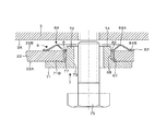
図8は図4のB−B断面図であり、ボルト締付け前の状態を示す断面図である。図9は図4のB−B断面図であり、ボルト締付け後の状態を示す断面図である。図10は図4のC−C断面図であり、ボルト締付け前の状態を示す断面図である。 8 is a cross-sectional view taken along the line BB of FIG. 4 and is a cross-sectional view showing a state before bolt tightening. 9 is a cross-sectional view taken along the line BB in FIG. 4 and is a cross-sectional view showing a state after the bolt is tightened. FIG. 10 is a cross-sectional view taken along the line CC of FIG. 4 and is a cross-sectional view showing a state before bolt tightening.
図4から図10に示すように、フランジ部22を車体3へ取付けるカプセルは、カラー7、リング8、ブッシュ6、ボルト75(図8参照)によって構成されている。カラー7は、導電性の材料で成形されており、切欠き溝25の最も幅の狭い部分の溝幅Wよりも大径の大径フランジ部71と、切欠き溝25の溝幅Wよりも外径が小さい小径筒部72で構成され、その軸心には、ボルト75を挿入するための貫通孔73が形成されている。大径フランジ部71の上面71Bは、フランジ部22の下面22Aに当接可能である。
As shown in FIGS. 4 to 10, the capsule for attaching the
小径筒部72の外周面77は円形に形成され、その軸心の貫通孔73は楕円形に形成されて、楕円形の長軸が車体前後方向(図4の左右方向)に形成され、短軸が車体左右方向(図4の上下方向)に形成されている。カラー7の材料としては、低炭素鋼、アルミニウム、マグネシウム等が考えられる。
The outer
カラー7の大径フランジ部71の外周には、円周上の二箇所に、円弧状の凹部(切欠き溝)76、76が形成されている。円弧状の凹部76、76は、大径フランジ部71の外周上の180度対向した位置で、カラー7の貫通孔73の楕円形の長軸の延長上に形成されている。
On the outer periphery of the large-
リング8は、切欠き溝25の溝幅Wよりも大径の外形形状を有し、導電性の円盤状の薄板から成形されており、円盤状の薄板を、所望の断面形状にプレスで折り曲げて成形している。リング8は、フランジ部22の上面22B側と車体3の下面3Aとの間に挿入される。
The
リング8の中心には丸孔81が形成され、丸孔81には、その円周上に等間隔に3個の爪82が、リング8の中心に向かって放射状に形成されている。爪82の内側に接する内接円の直径寸法は、小径筒部72の外周面77の外径寸法より若干小径に形成されている。
A
従って、リング8をカラー7の小径筒部72の外周面77に押し込むと、爪82が放射方向外側に押し広げられながら、小径筒部72の外周面77に嵌入し、爪82の弾力で爪82の内側が小径筒部72の外周面77に食い込むため、リング8とカラー7が結合する。すなわち、爪82はプッシュナットの機能を有している。
Therefore, when the
リング8の材料としては、ステンンレス鋼板、高張力鋼板、圧延鋼板等が考えられるが、ばね鋼が最も好ましい。また、リング8の材料硬度は、HRC35〜40が好ましい。
As a material for the
ブッシュ6は、車体前方側が中空円筒形状をしており、その中空円筒部の外周面67の外径寸法を、切欠き溝25の最も幅の狭い部分の溝幅Wに丁度内嵌する寸法に設定している。ブッシュ6の中空円筒部の内周面68の内径寸法は、カラー7の小径筒部72の外周面77の外径に丁度外嵌する寸法に設定する。ブッシュ6の材質は、摩擦係数の小さなポリアセタール(POM)等の樹脂や、金属に低摩擦材をコーティングしたものが好ましい。
The
また、ブッシュ6には、車体後方側に向かって延びる後方延長部61が形成され、後方延長部61には車体左右方向の中間位置に、車体前方側が開放されて、内周面68に連通している略U字形状の切欠き溝62が形成されている。
Further, the
後方延長部61の車体左右方向の幅は、フランジ部22の切欠き溝25の最も幅の狭い部分の溝幅Wに丁度内嵌する寸法に設定されている。ブッシュ6の後方延長部61を、切欠き溝25に組み込むと、ブッシュ6は切欠き溝25に内嵌して、切欠き溝25内に回り止めされて、位置決めされる。
The width of the
切欠き溝25は、車体後方側に向かって徐々に拡幅しているため、ブッシュ6の後方延長部61を、切欠き溝25に組み込むのが容易な構成になっている。後方延長部61には、リング8の外周83よりも外側に、フランジ部22の上面22B側よりも車体3側に向かって突出する突出部63が形成されている。
Since the
突出部63の車体左右方向の幅は、切欠き溝25の最も幅の広い部分の溝幅よりも広く形成され、突出部63の上面には、車体3の下面3Aと対向する当接面64が形成されている。
The width of the protruding
また、ブッシュ6の後方延長部61には、フランジ部22の下面22Aよりも車体下方側に向かって突出し、断面が矩形の凸部65が形成されている。凸部65の車体左右方向の幅は、カラー7の円弧状の凹部76の車体左右方向の幅よりも若干狭く形成されている。
Further, the
凸部65の車体前方端は、カラー7の円弧状の凹部76と同一曲率半径の円弧状に形成されている。また、凸部65は、凹部76、76の中心を結ぶ延長線上(カラー7の貫通孔73の楕円形の長軸の延長上)に形成されている。
The front end of the vehicle body of the
従って、ブッシュ6を切欠き溝25に車体後方側から挿入した後、ブッシュ6にカラー7の小径筒部72を車体下方側から内嵌する。この時、カラー7の貫通孔73の楕円形の長軸を切欠き溝25に平行(車体前後方向)にする。すると、ブッシュ6とカラー7は、カラー7の車体後方側の凹部76がブッシュ6の凸部65に係合し、ブッシュ6に対してカラー7が回り止めされる。
Accordingly, after the
カラー7の凹部76は、180度対向した円周上の二箇所に形成されている。従って、ブッシュ6にカラー7を組み付ける際、カラー7の車体前後方向の向きを気にする必要がないため、カラー7の組み付けが容易になる。
The
その後、リング8をカラー7の上方から、カラー7の小径筒部72の外周面77に押し込むと、リング8の爪82が放射方向外側に押し広げられながら、小径筒部72の外周面77に嵌入し、爪82の弾力で爪82の内側が小径筒部72の外周面77に食い込む。
Thereafter, when the
その結果、リング8、ブッシュ6、カラー7が結合し、ステアリング装置を車体への取付け位置に仮り置きした場合に、リング8、ブッシュ6、カラー7が切欠き溝25の車体後方側に抜け出さない。
As a result, the
このようにすれば、ステアリング装置を車体にボルト75で取り付けるまでの間、カラー7がアッパー側車体取付けブラケット2に対して回転しないため、カラー7の楕円形の貫通孔73の長軸の方向が車体前後方向に平行に維持される。
By doing so, the
この状態でボルト75をカラー7の貫通孔73に挿入して、車体3にボルトをねじ込んで行く。カラー7の貫通孔73は、車体前後方向が長い楕円形に形成されている。従って、組付け時、カラー7、ブッシュ6、リング8は、車体前後方向に、ボルトの外径と貫通孔73との間の隙間の分だけ位置調整ができる。
In this state, the
そのため、車体3側の車体前後方向のボルト孔の位置のばらつきや、ロアー側車体取付けブラケット15とアッパー側車体取付けブラケット2との間の車体前後方向の製作誤差を吸収して、容易に取付けることができる。
For this reason, it can be easily mounted by absorbing variations in the position of the bolt holes in the longitudinal direction of the vehicle body on the side of the
リング8の丸孔81の周囲には、断面が山型に湾曲した弾性変形部84が環状に形成され、弾性変形部84の山型の頂点84A側が車体3側に面し、山型の底点84B側がフランジ部22側に面している。図10に示すように、ボルト締付け前の状態では、フランジ部22の下面22Aから弾性変形部82の山型の頂点82Aまでの高さH1は、小径筒部72の高さH2よりも高くなるように設定されている。
Around the
また、フランジ部22の下面22Aからブッシュ6の当接面64までの高さH3は、小径筒部72の高さH2よりも低くなるように設定されている。また、フランジ部22の上面22Bからブッシュ6の当接面64までの高さH4は、リング8の板厚Tよりも高くなるように設定されている。
The height H3 from the
ボルト75をカラー7の貫通孔73に挿入して、車体3にボルトをねじ込んで行くと、リング8の弾性変形部84はボルトの締付け力によって潰れる。小径筒部72の上端面74が車体3の下面3Aに当接するまでボルトは締付けられ、高さH1とH2の差の分だけリング8の弾性変形部84は潰れる。
When the
このリング8の弾性変形部84が潰れた時の弾力で、図9に示すように、フランジ部22は車体3に締付けられ、アッパー側車体取付けブラケット2が車体3から離脱する時の離脱荷重が設定される。
With the elasticity when the elastically deforming
この状態で、自動車が他の自動車等に衝突し、運転者が慣性でステアリングホイール12に二次衝突し、ステアリングホイール12を上方に跳ね上げる方向の衝撃力が作用すると、図10でフランジ部22の車体後方側を上に跳ね上げる方向に衝撃力が作用する。この衝撃力で、フランジ部22の車体後方側が上に跳ね上げられると、リング8の弾性変形部84の車体後方側が潰れ、ブッシュ6の当接面64が車体3の下面3Aに当接する。
In this state, when the automobile collides with another automobile or the like, the driver collides with the
従って、リング8の弾性変形部84がそれ以上に潰れて離脱荷重が増大するのを阻止し、フランジ部22の車体後方側が上に跳ね上げられるのを阻止する。そのため、フランジ部22は、カラー7、リング8、ブッシュ6を車体3側に残して、車体前方側に円滑に移動し、二次衝突時の衝撃を緩和することが可能となる。
Accordingly, the
カラー7を回り止めするカラー7の凹部76、76とブッシュ6の凸部65は、車体前後方向に平行に形成されているため、フランジ部22が車体前方側に移動する際に、余分な離脱荷重を生じることがない。そのため、フランジ部22は、車体前方側に円滑に移動して、二次衝突時の衝撃を緩和することができる。
Since the
上記した実施例1では、カラー7に形成された凹部76が、ブッシュ6に形成された凸部65に係合して、ブッシュ6に対してカラー7が回り止めされているが、カラー7に凸部を形成し、この凸部がブッシュ6に形成された凹部に係合して、ブッシュ6に対してカラー7を回り止めしてもよい。
In the first embodiment described above, the
ボルト75の六角頭部の直径が、図6のカラー7の大径フランジ部71の直径Dよりも大きいと、六角頭部がブッシュ6の凸部65に干渉して、ボルト75が締付けられない。その場合には、ブッシュ6の凸部65の高さH5を、大径フランジ部71の高さH6よりも低くすればよい。
When the diameter of the hexagonal head of the
その場合、ボルト75を締め付けた時に、カラー7がボルト75と共回りする恐れがある。カラー7の共回りを防ぐためには、ブッシュ6の凸部65に追加して、カラー7の車体前方側の凹部76に係合してカラー7を回り止めする凸部を、フランジ部22の下面22Aに突出させて形成すればよい。
In that case, when the
次に本発明の実施例2について説明する。図11(1)は本発明の実施例2のカプセルを車体上方側から見た斜視図、図11(2)は図11(1)の分解斜視図である。図12は本発明の実施例2のカプセルを車体下方側から見た斜視図である。図13は図12の分解斜視図である。図14は本発明の実施例2のカプセルのボルト締付け前の状態を示す断面図であり、図4のB−B断面図相当である。以下の説明では、上記実施例と異なる構造部分についてのみ説明し、重複する説明は省略する。また、同一部品には同一番号を付して説明する。 Next, a second embodiment of the present invention will be described. FIG. 11 (1) is a perspective view of the capsule according to the second embodiment of the present invention as viewed from above the vehicle body, and FIG. 11 (2) is an exploded perspective view of FIG. 11 (1). FIG. 12 is a perspective view of the capsule according to the second embodiment of the present invention as viewed from the lower side of the vehicle body. FIG. 13 is an exploded perspective view of FIG. 14 is a cross-sectional view showing a state of the capsule according to the second embodiment of the present invention before bolt tightening, and corresponds to a cross-sectional view taken along the line BB of FIG. In the following description, only structural parts different from the above-described embodiment will be described, and redundant description will be omitted. Further, the same parts will be described with the same numbers.
実施例2は、カラー7の凹部76に係合してカラー7を回り止めする凸部65を、アッパー側車体取付けブラケット2に形成した例である。すなわち、図11から図14に示すように、実施例2では、実施例1と同様に、フランジ部22を車体3へ取付けるカプセルは、カラー7、リング8、ブッシュ6、ボルト75によって構成されている。
The second embodiment is an example in which a
カラー7とリング8は、実施例1と同一部品で構成され、カラー7の大径フランジ部71の外周には、実施例1と同様に、大径フランジ部71の外周上の180度対向した位置で、カラー7の貫通孔73の楕円形の長軸の延長上に、円弧状の凹部76、76が形成されている。
The
ブッシュ6の後方延長部61には、カラー7の円弧状の凹部76、76に係合する凸部65は形成されていない。その代わりに、フランジ部22の下面22Aには、切欠き溝25の車体前方端よりも車体前方側に、フランジ部22の下面22Aよりも車体下方側に向かって突出し、円柱状の形状を有する凸部26が形成されている。凸部26の円柱の直径は、カラー7の円弧状の凹部76の車体左右方向の幅よりも若干小さく形成されている。
The
また、凸部26は、凹部76、76の中心を結ぶ延長線上(カラー7の貫通孔73の楕円形の長軸の延長上)に形成されている。図13に示す凸部26の高さH7は、カラー7の大径フランジ部71の高さH6と同一、または、低くしてもよい。
Further, the
ブッシュ6を切欠き溝25に車体後方側から挿入した後、ブッシュ6にカラー7の小径筒部72を車体下方側から内嵌する。この時、カラー7の貫通孔73の楕円形の長軸を切欠き溝25に平行(車体前後方向)にする。すると、カラー7の車体前方側の凹部76がフランジ部22の下面22Aの凸部26に係合し、フランジ部22に対してカラー7が回り止めされる。
After the
その後、リング8をカラー7の上方から、カラー7の小径筒部72の外周面77に押し込むと、リング8の爪82が放射方向外側に押し広げられながら、小径筒部72の外周面77に嵌入し、爪82の弾力で爪82の内側が小径筒部72の外周面77に食い込む。
Thereafter, when the
その結果、リング8、ブッシュ6、カラー7が結合し、ステアリング装置を車体への取付け位置に仮り置きした場合に、リング8、ブッシュ6、カラー7が切欠き溝25の車体後方側に抜け出さない。
As a result, the
このようにすれば、ステアリング装置を車体にボルト75で取り付けるまでの間、カラー7がアッパー側車体取付けブラケット2に対して回転しないため、カラー7の楕円形の貫通孔73の長軸の方向が車体前後方向に平行に維持される。
By doing so, the
この状態でボルト75をカラー7の貫通孔73に挿入して、車体3にボルトをねじ込んで行く。カラー7の貫通孔73は、車体前後方向が長い楕円形に形成されている。従って、組付け時、カラー7、ブッシュ6、リング8は、車体前後方向に、ボルトの外径と貫通孔73との間の隙間の分だけ位置調整ができる。そのため、車体3側の車体前後方向のボルト孔の位置のばらつきや、ロアー側車体取付けブラケット15とアッパー側車体取付けブラケット2との間の車体前後方向の製作誤差を吸収して、容易に取付けることができる。
In this state, the
カラー7を回り止めするカラー7の凹部76とフランジ部22の凸部26は、車体前後方向に平行に形成されているため、フランジ部22が車体前方側に移動する際に、余分な離脱荷重を生じることがない。そのため、フランジ部22は、車体前方側に円滑に移動して、二次衝突時の衝撃を緩和することができる。
Since the
上記した実施例2では、カラー7に形成された凹部76が、フランジ部22に形成された凸部26に係合して、フランジ部22に対してカラー7が回り止めされているが、カラー7に凸部を形成し、この凸部がフランジ部22に形成された凹部に係合して、フランジ部22に対してカラー7を回り止めしてもよい。
In Example 2 described above, the
次に本発明の実施例3について説明する。図15(1)は本発明の実施例3のカプセルを車体上方側から見た斜視図、図15(2)は図15(1)の分解斜視図である。図16は本発明の実施例3のカプセルを車体下方側から見た斜視図である。図17は図16の分解斜視図である。図18は本発明の実施例3のカプセルのボルト締付け前の状態を示す断面図であり、図4のB−B断面図相当である。以下の説明では、上記実施例と異なる構造部分についてのみ説明し、重複する説明は省略する。また、同一部品には同一番号を付して説明する。 Next, a third embodiment of the present invention will be described. FIG. 15 (1) is a perspective view of the capsule according to the third embodiment of the present invention as viewed from above the vehicle body, and FIG. 15 (2) is an exploded perspective view of FIG. 15 (1). FIG. 16 is a perspective view of the capsule according to the third embodiment of the present invention as viewed from the lower side of the vehicle body. 17 is an exploded perspective view of FIG. 18 is a cross-sectional view showing a state of the capsule according to the third embodiment of the present invention before bolt tightening, and corresponds to a cross-sectional view taken along the line BB of FIG. In the following description, only structural parts different from the above-described embodiment will be described, and redundant description will be omitted. Further, the same parts will be described with the same numbers.
実施例3は、カラー7に対するリング8の抜け止めを確実に行うようにした例である。すなわち、図15から図18に示すように、実施例3では、実施例1と同様に、フランジ部22を車体3へ取付けるカプセルは、カラー7、リング8、ブッシュ6、ボルト75によって構成されている。
The third embodiment is an example in which the
ブッシュ6は、実施例1と同一部品で構成され、カラー7の大径フランジ部71の外周には、実施例1と同様に、大径フランジ部71の外周上の180度対向した位置で、カラー7の貫通孔73の楕円形の長軸の延長上に、円弧状の凹部76、76が形成されている。また、ブッシュ6の後方延長部61には、実施例1と同様に、カラー7の円弧状の凹部76、76に係合する凸部65が形成されている。
The
リング8の中心には、カラー7の小径筒部72の外周面77の外径寸法より若干大径の丸孔81が形成され、丸孔81には、実施例1の爪82は形成されていない。その代わりに、カラー7の小径筒部72の外周面77の上端外周には、円周上の180度対向した位置の二箇所に、係合突起78が形成されている。
In the center of the
係合突起78は、車体上方側から車体下方側に向かって拡径する傾斜面を有する鋸歯状で、リング8の丸孔81の内径寸法よりも半径方向外側に突出して形成されている。
The
ブッシュ6を切欠き溝25に車体後方側から挿入した後、ブッシュ6にカラー7の小径筒部72を車体下方側から内嵌する。この時、カラー7の貫通孔73の楕円形の長軸を切欠き溝25に平行(車体前後方向)にする。すると、ブッシュ6とカラー7は、実施例1と同様に、カラー7の車体後方側の凹部76がブッシュ6の凸部65に係合し、ブッシュ6とカラー7が回り止めされる。
After the
その後、リング8をカラー7の上方から、カラー7の小径筒部72の外周面77に押し込むと、リング8の丸孔81が係合突起78の車体上方側の傾斜面に沿って放射方向外側に押し広げられながら、小径筒部72の外周面77に嵌入する。その結果、リング8の丸孔81は、フランジ部22の上面22Bと係合突起78の下面に挟持される。そのため、カラー7に対するリング8の車体上方側への抜け止めが確実になされ、リング8、ブッシュ6、カラー7が結合する。
Thereafter, when the
その結果、ステアリング装置を車体への取付け位置に仮り置きした場合に、リング8、ブッシュ6、カラー7が切欠き溝25の車体後方側に抜け出さない。
As a result, when the steering device is temporarily placed at the mounting position on the vehicle body, the
このようにすれば、ステアリング装置を車体にボルト75で取り付けるまでの間、カラー7がアッパー側車体取付けブラケット2に対して回転しないため、カラー7の楕円形の貫通孔73の長軸の方向が車体前後方向に平行に維持される。
By doing so, the
この状態でボルト75をカラー7の貫通孔73に挿入して、車体3にボルトをねじ込んで行く。カラー7の貫通孔73は、車体前後方向が長い楕円形に形成されている。従って、組付け時、カラー7、ブッシュ6、リング8は、車体前後方向に、ボルトの外径と貫通孔73との間の隙間の分だけ位置調整ができる。そのため、車体3側の車体前後方向のボルト孔の位置のばらつきや、ロアー側車体取付けブラケット15とアッパー側車体取付けブラケット2との間の車体前後方向の製作誤差を吸収して、容易に取付けることができる。
In this state, the
上記実施例では、リング8の中心は楕円孔では無く、丸孔81が形成されているので、リング8を組み付ける際に、リング8の位相を気にせずに組み付けることができる。
In the above embodiment, the center of the
また、上記実施例では、フランジ部22、リング8、カラー7の小径筒部72の高さに誤差があっても、リング8が潰れることで、これらの高さの誤差を吸収し、一定の離脱荷重でアッパー側車体取付けブラケット2を車体3に取付けることが可能となる。また、樹脂ピンを介さない取付け方法であるため、振動剛性が高く、通電経路が確実に確保される。
Moreover, in the said Example, even if there is an error in the height of the
さらに、上記実施例では、チルト位置調整だけが可能なチルト式のステアリング装置に本発明を適用した場合について説明したが、チルト位置調整とテレスコピック位置調整の両方が可能なチルト・テレスコピック式のステアリング装置に本発明を適用してもよい。 Furthermore, in the above embodiment, the case where the present invention is applied to a tilt type steering apparatus capable of only tilt position adjustment has been described. However, a tilt / telescopic type steering apparatus capable of both tilt position adjustment and telescopic position adjustment is described. The present invention may be applied to.
11 アウターコラム
12 ステアリングホイール
13 ステアリングシャフト
14 インナーコラム
15 ロアー側車体取付けブラケット
16 ピボットピン
2 アッパー側車体取付けブラケット
21、22 フランジ部
22A 下面
22B 上面
23、24 側板
231、241 チルト用長溝
25 切欠き溝
26 凸部
3 車体
3A 下面
4 ディスタンスブラケット
41、42 側板
411、421 貫通孔
51 締付けロッド
511 頭部
512 回り止め部
52 締付けナット
53 ワッシャ
54 調整ナット
55 雄ねじ
56 操作レバー
6 ブッシュ
61 後方延長部
62 切欠き溝
63 突出部
64 当接面
65 凸部
67 外周面
68 内周面
7 カラー
71 大径フランジ部
71B 上面
72 小径筒部
73 貫通孔
74 上端面
75 ボルト
76 凹部
77 外周面
78 係合突起
8 リング
81 丸孔
82 爪
83 外周
84 弾性変形部
84A 頂点
84B 底点
DESCRIPTION OF
Claims (4)
上記ステアリングシャフトを回動可能に軸支するコラム、
車体後方側が開放された切欠き溝を有するフランジ部を上記車体に固定して上記コラムを支持すると共に、二次衝突時に車体前方側に離脱可能な車体取付けブラケット、
上記切欠き溝の溝幅よりも大径の大径フランジ部と、上記切欠き溝に挿通可能な小径筒部とを有するカラー、
上記小径筒部の軸心に形成され、車体前後方向が長軸の楕円形に形成された貫通孔、
上記切欠き溝の溝幅よりも大径の外形形状を有し、上記小径筒部を挿通可能な孔が形成された弾性変形可能なリング、
上記カラーの小径筒部の外周面と切欠き溝との間に挿入され、切欠き溝に対して相対回転不能なブッシュ、
上記貫通孔に挿通され、上記フランジ部の切欠き溝の周囲を上記カラーの大径フランジ部と上記リングで挟持して、上記車体取付けブラケットを車体に締付けるボルト、
上記カラーの大径フランジ部の外周に形成された凹部、
上記ブッシュに形成され、上記カラーの凹部に係合して、上記カラーを車体取付けブラケットに対して回り止めする凸部
を備えたステアリング装置であって、
上記カラーの凹部は、上記カラーの貫通孔の楕円形の長軸の延長上で、180度対向した二箇所に形成されているとともに、
上記ブッシュの凸部は、上記ブッシュの車体後方側に形成され、上記切欠き溝に内嵌する後方延長部に、上記車体取付けブラケットのフランジ部の下面よりも車体下方側に向かって突出して形成されていること
を特徴とするステアリング装置。 Steering shaft that can be fitted with a steering wheel on the rear side of the vehicle body,
A column that pivotally supports the steering shaft,
A vehicle body mounting bracket that supports the column by fixing a flange portion having a notch groove that is open on the rear side of the vehicle body to the vehicle body, and that can be detached to the front side of the vehicle body at the time of a secondary collision,
A collar having a large-diameter flange portion larger in diameter than the groove width of the notch groove, and a small-diameter cylindrical portion that can be inserted into the notch groove;
A through-hole formed in the axis of the small-diameter cylindrical portion and formed in an elliptical shape with the longitudinal direction of the vehicle body being a long axis
An elastically deformable ring having an outer shape larger in diameter than the groove width of the notch groove and formed with a hole through which the small diameter cylindrical portion can be inserted;
A bush that is inserted between the outer peripheral surface of the small-diameter cylindrical portion of the collar and the notch groove and cannot rotate relative to the notch groove;
A bolt that is inserted into the through-hole, clamps the periphery of the notch groove of the flange portion with the large-diameter flange portion of the collar and the ring, and tightens the vehicle body mounting bracket to the vehicle body,
A recess formed on the outer periphery of the large-diameter flange portion of the collar,
A steering device provided with a convex portion that is formed on the bush, engages with a concave portion of the collar, and prevents the collar from rotating relative to a vehicle body mounting bracket ;
The concave portion of the collar is formed at two locations opposed to each other by 180 degrees on the extension of the elliptical long axis of the through hole of the collar,
The convex part of the bush is formed on the rear side of the vehicle body of the bush, and is formed on the rear extension part fitted in the notch groove so as to protrude downward from the lower surface of the flange part of the body mounting bracket. The steering apparatus characterized by being made .
上記リングの孔には、上記カラーの小径筒部の外周面に圧入されて食い込む複数の爪が形成されていること
を特徴とするステアリング装置。 The steering apparatus according to claim 1 , wherein
A steering device according to claim 1, wherein a plurality of claws are formed in the hole of the ring so as to be pressed into the outer peripheral surface of the small-diameter cylindrical portion of the collar.
上記カラーの上端に形成され、上記リングを上記車体取付けブラケットのフランジ部との間で挟持する係合突起を備えたこと
を特徴とするステアリング装置。 The steering apparatus according to claim 1 , wherein
A steering apparatus comprising an engagement protrusion formed on an upper end of the collar and sandwiching the ring with a flange portion of the vehicle body mounting bracket.
上記ブッシュは、上記リングの外周よりも外側に、上記車体取付けブラケットのフランジ部とリングとの当接面よりも車体側に突出した当接面を有していること
を特徴とするステアリング装置。 The steering apparatus according to claim 1 , wherein
The steering device according to claim 1, wherein the bush has a contact surface that protrudes further toward the vehicle body side than a contact surface between the flange portion of the vehicle body mounting bracket and the ring outside the outer periphery of the ring.
Priority Applications (1)
| Application Number | Priority Date | Filing Date | Title |
|---|---|---|---|
| JP2008190929A JP5045593B2 (en) | 2008-07-24 | 2008-07-24 | Steering device |
Applications Claiming Priority (1)
| Application Number | Priority Date | Filing Date | Title |
|---|---|---|---|
| JP2008190929A JP5045593B2 (en) | 2008-07-24 | 2008-07-24 | Steering device |
Publications (2)
| Publication Number | Publication Date |
|---|---|
| JP2010023797A JP2010023797A (en) | 2010-02-04 |
| JP5045593B2 true JP5045593B2 (en) | 2012-10-10 |
Family
ID=41730004
Family Applications (1)
| Application Number | Title | Priority Date | Filing Date |
|---|---|---|---|
| JP2008190929A Expired - Fee Related JP5045593B2 (en) | 2008-07-24 | 2008-07-24 | Steering device |
Country Status (1)
| Country | Link |
|---|---|
| JP (1) | JP5045593B2 (en) |
Families Citing this family (1)
| Publication number | Priority date | Publication date | Assignee | Title |
|---|---|---|---|---|
| DE102020215469A1 (en) | 2020-12-08 | 2022-06-09 | Thyssenkrupp Ag | Steering column for an automobile and motor vehicle |
Family Cites Families (2)
| Publication number | Priority date | Publication date | Assignee | Title |
|---|---|---|---|---|
| JP2005280498A (en) * | 2004-03-30 | 2005-10-13 | Nsk Ltd | Energy absorbing steering column |
| JP4952875B2 (en) * | 2004-06-04 | 2012-06-13 | 日本精工株式会社 | Steering column device |
-
2008
- 2008-07-24 JP JP2008190929A patent/JP5045593B2/en not_active Expired - Fee Related
Also Published As
| Publication number | Publication date |
|---|---|
| JP2010023797A (en) | 2010-02-04 |
Similar Documents
| Publication | Publication Date | Title |
|---|---|---|
| JP4952875B2 (en) | Steering column device | |
| JP5333417B2 (en) | Steering device | |
| JP5528868B2 (en) | Steering device | |
| JP6052477B2 (en) | Steering column device | |
| JP5370520B2 (en) | Steering device | |
| JP5708838B2 (en) | Steering device | |
| JP7079147B2 (en) | Steering column | |
| US11225280B2 (en) | Steering device | |
| JP3591284B2 (en) | Swing support device for steering column for tilt type steering device | |
| JP2008018803A (en) | Steering device | |
| JP5045593B2 (en) | Steering device | |
| JPH09272446A (en) | Tilt type steering device | |
| JP6673457B2 (en) | Steering column device | |
| JP2009090894A (en) | Steering device | |
| JP5338766B2 (en) | Steering device | |
| JP5135862B2 (en) | Steering device | |
| JP3244591B2 (en) | Tilt steering system | |
| JP5465426B2 (en) | Tilt telescopic steering device | |
| JP6759746B2 (en) | Steering device | |
| JP6819241B2 (en) | Steering device | |
| JP4640999B2 (en) | Push-on-fix for locking aiming screw | |
| EP3812241A1 (en) | Steering column device | |
| JP2018130995A (en) | Steering unit | |
| JP6503864B2 (en) | Steering device | |
| JP2005329840A (en) | Steering column device |
Legal Events
| Date | Code | Title | Description |
|---|---|---|---|
| A621 | Written request for application examination |
Free format text: JAPANESE INTERMEDIATE CODE: A621 Effective date: 20110105 |
|
| A131 | Notification of reasons for refusal |
Free format text: JAPANESE INTERMEDIATE CODE: A131 Effective date: 20120522 |
|
| A977 | Report on retrieval |
Free format text: JAPANESE INTERMEDIATE CODE: A971007 Effective date: 20120524 |
|
| A521 | Written amendment |
Free format text: JAPANESE INTERMEDIATE CODE: A523 Effective date: 20120528 |
|
| TRDD | Decision of grant or rejection written | ||
| A01 | Written decision to grant a patent or to grant a registration (utility model) |
Free format text: JAPANESE INTERMEDIATE CODE: A01 Effective date: 20120619 |
|
| A01 | Written decision to grant a patent or to grant a registration (utility model) |
Free format text: JAPANESE INTERMEDIATE CODE: A01 |
|
| A61 | First payment of annual fees (during grant procedure) |
Free format text: JAPANESE INTERMEDIATE CODE: A61 Effective date: 20120702 |
|
| FPAY | Renewal fee payment (event date is renewal date of database) |
Free format text: PAYMENT UNTIL: 20150727 Year of fee payment: 3 |
|
| R150 | Certificate of patent or registration of utility model |
Ref document number: 5045593 Country of ref document: JP Free format text: JAPANESE INTERMEDIATE CODE: R150 Free format text: JAPANESE INTERMEDIATE CODE: R150 |
|
| LAPS | Cancellation because of no payment of annual fees |