JP5045542B2 - Long volume hologram layer transfer foil, method of manufacturing volume hologram laminate using the same, and volume hologram laminate - Google Patents
Long volume hologram layer transfer foil, method of manufacturing volume hologram laminate using the same, and volume hologram laminate Download PDFInfo
- Publication number
- JP5045542B2 JP5045542B2 JP2008123713A JP2008123713A JP5045542B2 JP 5045542 B2 JP5045542 B2 JP 5045542B2 JP 2008123713 A JP2008123713 A JP 2008123713A JP 2008123713 A JP2008123713 A JP 2008123713A JP 5045542 B2 JP5045542 B2 JP 5045542B2
- Authority
- JP
- Japan
- Prior art keywords
- volume hologram
- hologram layer
- layer
- transfer foil
- long
- Prior art date
- Legal status (The legal status is an assumption and is not a legal conclusion. Google has not performed a legal analysis and makes no representation as to the accuracy of the status listed.)
- Active
Links
- 238000012546 transfer Methods 0.000 title claims description 333
- 239000011888 foil Substances 0.000 title claims description 204
- 238000004519 manufacturing process Methods 0.000 title claims description 22
- 239000010410 layer Substances 0.000 claims description 493
- 239000000463 material Substances 0.000 claims description 81
- 239000002243 precursor Substances 0.000 claims description 56
- 230000002265 prevention Effects 0.000 claims description 48
- 239000011241 protective layer Substances 0.000 claims description 36
- 239000000758 substrate Substances 0.000 claims description 29
- 238000010438 heat treatment Methods 0.000 claims description 17
- 229920005992 thermoplastic resin Polymers 0.000 claims description 14
- 238000000034 method Methods 0.000 description 38
- 229920005989 resin Polymers 0.000 description 35
- 239000011347 resin Substances 0.000 description 35
- 150000001875 compounds Chemical class 0.000 description 32
- -1 amide compounds Chemical class 0.000 description 25
- 239000000975 dye Substances 0.000 description 21
- 150000003254 radicals Chemical class 0.000 description 16
- 230000000694 effects Effects 0.000 description 13
- 239000003999 initiator Substances 0.000 description 12
- 239000000203 mixture Substances 0.000 description 12
- 230000008569 process Effects 0.000 description 11
- 239000011230 binding agent Substances 0.000 description 10
- 230000001771 impaired effect Effects 0.000 description 8
- 125000002091 cationic group Chemical group 0.000 description 7
- 238000005520 cutting process Methods 0.000 description 7
- 239000000178 monomer Substances 0.000 description 7
- ZWEHNKRNPOVVGH-UHFFFAOYSA-N 2-Butanone Chemical compound CCC(C)=O ZWEHNKRNPOVVGH-UHFFFAOYSA-N 0.000 description 6
- YXFVVABEGXRONW-UHFFFAOYSA-N Toluene Chemical compound CC1=CC=CC=C1 YXFVVABEGXRONW-UHFFFAOYSA-N 0.000 description 6
- 150000002496 iodine Chemical class 0.000 description 6
- 229920003229 poly(methyl methacrylate) Polymers 0.000 description 6
- 239000004926 polymethyl methacrylate Substances 0.000 description 6
- 229920002554 vinyl polymer Polymers 0.000 description 6
- 229920002799 BoPET Polymers 0.000 description 5
- 230000004888 barrier function Effects 0.000 description 5
- 230000008901 benefit Effects 0.000 description 5
- 125000005520 diaryliodonium group Chemical group 0.000 description 5
- QGKMIGUHVLGJBR-UHFFFAOYSA-M (4z)-1-(3-methylbutyl)-4-[[1-(3-methylbutyl)quinolin-1-ium-4-yl]methylidene]quinoline;iodide Chemical compound [I-].C12=CC=CC=C2N(CCC(C)C)C=CC1=CC1=CC=[N+](CCC(C)C)C2=CC=CC=C12 QGKMIGUHVLGJBR-UHFFFAOYSA-M 0.000 description 4
- NIXOWILDQLNWCW-UHFFFAOYSA-N 2-Propenoic acid Natural products OC(=O)C=C NIXOWILDQLNWCW-UHFFFAOYSA-N 0.000 description 4
- FBPFZTCFMRRESA-FSIIMWSLSA-N D-Glucitol Natural products OC[C@H](O)[C@H](O)[C@@H](O)[C@H](O)CO FBPFZTCFMRRESA-FSIIMWSLSA-N 0.000 description 4
- FBPFZTCFMRRESA-JGWLITMVSA-N D-glucitol Chemical compound OC[C@H](O)[C@@H](O)[C@H](O)[C@H](O)CO FBPFZTCFMRRESA-JGWLITMVSA-N 0.000 description 4
- RTZKZFJDLAIYFH-UHFFFAOYSA-N Diethyl ether Chemical compound CCOCC RTZKZFJDLAIYFH-UHFFFAOYSA-N 0.000 description 4
- 125000001931 aliphatic group Chemical group 0.000 description 4
- 150000001732 carboxylic acid derivatives Chemical class 0.000 description 4
- 229920001577 copolymer Polymers 0.000 description 4
- 230000001678 irradiating effect Effects 0.000 description 4
- 229920002689 polyvinyl acetate Polymers 0.000 description 4
- 239000011118 polyvinyl acetate Substances 0.000 description 4
- 239000007870 radical polymerization initiator Substances 0.000 description 4
- 230000001235 sensitizing effect Effects 0.000 description 4
- 239000000600 sorbitol Substances 0.000 description 4
- LDHQCZJRKDOVOX-UHFFFAOYSA-N trans-crotonic acid Natural products CC=CC(O)=O LDHQCZJRKDOVOX-UHFFFAOYSA-N 0.000 description 4
- SMZOUWXMTYCWNB-UHFFFAOYSA-N 2-(2-methoxy-5-methylphenyl)ethanamine Chemical compound COC1=CC=C(C)C=C1CCN SMZOUWXMTYCWNB-UHFFFAOYSA-N 0.000 description 3
- QTBSBXVTEAMEQO-UHFFFAOYSA-N Acetic acid Chemical compound CC(O)=O QTBSBXVTEAMEQO-UHFFFAOYSA-N 0.000 description 3
- 239000004925 Acrylic resin Substances 0.000 description 3
- KWIUHFFTVRNATP-UHFFFAOYSA-N Betaine Natural products C[N+](C)(C)CC([O-])=O KWIUHFFTVRNATP-UHFFFAOYSA-N 0.000 description 3
- VGGSQFUCUMXWEO-UHFFFAOYSA-N Ethene Chemical compound C=C VGGSQFUCUMXWEO-UHFFFAOYSA-N 0.000 description 3
- 239000005977 Ethylene Substances 0.000 description 3
- KWIUHFFTVRNATP-UHFFFAOYSA-O N,N,N-trimethylglycinium Chemical compound C[N+](C)(C)CC(O)=O KWIUHFFTVRNATP-UHFFFAOYSA-O 0.000 description 3
- BZHJMEDXRYGGRV-UHFFFAOYSA-N Vinyl chloride Chemical compound ClC=C BZHJMEDXRYGGRV-UHFFFAOYSA-N 0.000 description 3
- 229920002433 Vinyl chloride-vinyl acetate copolymer Polymers 0.000 description 3
- 150000001252 acrylic acid derivatives Chemical class 0.000 description 3
- 229960003237 betaine Drugs 0.000 description 3
- 150000001735 carboxylic acids Chemical class 0.000 description 3
- 238000012663 cationic photopolymerization Methods 0.000 description 3
- 230000002950 deficient Effects 0.000 description 3
- 238000013461 design Methods 0.000 description 3
- 150000002148 esters Chemical class 0.000 description 3
- 230000000149 penetrating effect Effects 0.000 description 3
- 229920001225 polyester resin Polymers 0.000 description 3
- 239000004645 polyester resin Substances 0.000 description 3
- 239000003505 polymerization initiator Substances 0.000 description 3
- 238000006116 polymerization reaction Methods 0.000 description 3
- 229920000915 polyvinyl chloride Polymers 0.000 description 3
- 239000004800 polyvinyl chloride Substances 0.000 description 3
- 238000007789 sealing Methods 0.000 description 3
- 239000002904 solvent Substances 0.000 description 3
- 125000000391 vinyl group Chemical group [H]C([*])=C([H])[H] 0.000 description 3
- DXUMYHZTYVPBEZ-UHFFFAOYSA-N 2,4,6-tris(trichloromethyl)-1,3,5-triazine Chemical compound ClC(Cl)(Cl)C1=NC(C(Cl)(Cl)Cl)=NC(C(Cl)(Cl)Cl)=N1 DXUMYHZTYVPBEZ-UHFFFAOYSA-N 0.000 description 2
- INQDDHNZXOAFFD-UHFFFAOYSA-N 2-[2-(2-prop-2-enoyloxyethoxy)ethoxy]ethyl prop-2-enoate Chemical compound C=CC(=O)OCCOCCOCCOC(=O)C=C INQDDHNZXOAFFD-UHFFFAOYSA-N 0.000 description 2
- KUDUQBURMYMBIJ-UHFFFAOYSA-N 2-prop-2-enoyloxyethyl prop-2-enoate Chemical compound C=CC(=O)OCCOC(=O)C=C KUDUQBURMYMBIJ-UHFFFAOYSA-N 0.000 description 2
- 229920000178 Acrylic resin Polymers 0.000 description 2
- 101100008044 Caenorhabditis elegans cut-1 gene Proteins 0.000 description 2
- 229920000877 Melamine resin Polymers 0.000 description 2
- CERQOIWHTDAKMF-UHFFFAOYSA-N Methacrylic acid Chemical compound CC(=C)C(O)=O CERQOIWHTDAKMF-UHFFFAOYSA-N 0.000 description 2
- LRHPLDYGYMQRHN-UHFFFAOYSA-N N-Butanol Chemical compound CCCCO LRHPLDYGYMQRHN-UHFFFAOYSA-N 0.000 description 2
- 206010034972 Photosensitivity reaction Diseases 0.000 description 2
- 239000004698 Polyethylene Substances 0.000 description 2
- 239000004743 Polypropylene Substances 0.000 description 2
- 239000004372 Polyvinyl alcohol Substances 0.000 description 2
- ATUOYWHBWRKTHZ-UHFFFAOYSA-N Propane Chemical compound CCC ATUOYWHBWRKTHZ-UHFFFAOYSA-N 0.000 description 2
- OFOBLEOULBTSOW-UHFFFAOYSA-N Propanedioic acid Natural products OC(=O)CC(O)=O OFOBLEOULBTSOW-UHFFFAOYSA-N 0.000 description 2
- SMWDFEZZVXVKRB-UHFFFAOYSA-N Quinoline Chemical compound N1=CC=CC2=CC=CC=C21 SMWDFEZZVXVKRB-UHFFFAOYSA-N 0.000 description 2
- PPBRXRYQALVLMV-UHFFFAOYSA-N Styrene Chemical compound C=CC1=CC=CC=C1 PPBRXRYQALVLMV-UHFFFAOYSA-N 0.000 description 2
- DHKHKXVYLBGOIT-UHFFFAOYSA-N acetaldehyde Diethyl Acetal Natural products CCOC(C)OCC DHKHKXVYLBGOIT-UHFFFAOYSA-N 0.000 description 2
- 239000002253 acid Substances 0.000 description 2
- 125000005396 acrylic acid ester group Chemical group 0.000 description 2
- 239000000654 additive Substances 0.000 description 2
- 239000012461 cellulose resin Substances 0.000 description 2
- 229920006026 co-polymeric resin Polymers 0.000 description 2
- 239000000470 constituent Substances 0.000 description 2
- 238000010586 diagram Methods 0.000 description 2
- 229920001971 elastomer Polymers 0.000 description 2
- 239000003822 epoxy resin Substances 0.000 description 2
- 239000012793 heat-sealing layer Substances 0.000 description 2
- 230000005865 ionizing radiation Effects 0.000 description 2
- VZCYOOQTPOCHFL-UPHRSURJSA-N maleic acid Chemical compound OC(=O)\C=C/C(O)=O VZCYOOQTPOCHFL-UPHRSURJSA-N 0.000 description 2
- 239000011976 maleic acid Substances 0.000 description 2
- FQPSGWSUVKBHSU-UHFFFAOYSA-N methacrylamide Chemical compound CC(=C)C(N)=O FQPSGWSUVKBHSU-UHFFFAOYSA-N 0.000 description 2
- 125000005395 methacrylic acid group Chemical group 0.000 description 2
- LVHBHZANLOWSRM-UHFFFAOYSA-N methylenebutanedioic acid Natural products OC(=O)CC(=C)C(O)=O LVHBHZANLOWSRM-UHFFFAOYSA-N 0.000 description 2
- 230000036211 photosensitivity Effects 0.000 description 2
- 239000004014 plasticizer Substances 0.000 description 2
- 229920002037 poly(vinyl butyral) polymer Polymers 0.000 description 2
- 229920000647 polyepoxide Polymers 0.000 description 2
- 229920000573 polyethylene Polymers 0.000 description 2
- 229920000139 polyethylene terephthalate Polymers 0.000 description 2
- 239000005020 polyethylene terephthalate Substances 0.000 description 2
- 229920001155 polypropylene Polymers 0.000 description 2
- 229920000346 polystyrene-polyisoprene block-polystyrene Polymers 0.000 description 2
- 229920002451 polyvinyl alcohol Polymers 0.000 description 2
- 238000002360 preparation method Methods 0.000 description 2
- 238000004080 punching Methods 0.000 description 2
- 239000005060 rubber Substances 0.000 description 2
- 229920002050 silicone resin Polymers 0.000 description 2
- 229920006132 styrene block copolymer Polymers 0.000 description 2
- 229920000468 styrene butadiene styrene block copolymer Polymers 0.000 description 2
- 150000005846 sugar alcohols Polymers 0.000 description 2
- OKYDCMQQLGECPI-UHFFFAOYSA-N thiopyrylium Chemical class C1=CC=[S+]C=C1 OKYDCMQQLGECPI-UHFFFAOYSA-N 0.000 description 2
- VZCYOOQTPOCHFL-UHFFFAOYSA-N trans-butenedioic acid Natural products OC(=O)C=CC(O)=O VZCYOOQTPOCHFL-UHFFFAOYSA-N 0.000 description 2
- 125000005409 triarylsulfonium group Chemical class 0.000 description 2
- WZKZYRSMAQLVTF-UHFFFAOYSA-N (2-butylphenyl)-phenyliodanium Chemical group C(CCC)C1=C(C=CC=C1)[I+]C1=CC=CC=C1 WZKZYRSMAQLVTF-UHFFFAOYSA-N 0.000 description 1
- FGTUGLXGCCYKPJ-SPIKMXEPSA-N (Z)-but-2-enedioic acid 2-[2-(2-hydroxyethoxy)ethoxy]ethanol Chemical compound OC(=O)\C=C/C(O)=O.OC(=O)\C=C/C(O)=O.OCCOCCOCCO FGTUGLXGCCYKPJ-SPIKMXEPSA-N 0.000 description 1
- 229920003067 (meth)acrylic acid ester copolymer Polymers 0.000 description 1
- SORHAFXJCOXOIC-CCAGOZQPSA-N (z)-4-[2-[(z)-3-carboxyprop-2-enoyl]oxyethoxy]-4-oxobut-2-enoic acid Chemical compound OC(=O)\C=C/C(=O)OCCOC(=O)\C=C/C(O)=O SORHAFXJCOXOIC-CCAGOZQPSA-N 0.000 description 1
- YHMYGUUIMTVXNW-UHFFFAOYSA-N 1,3-dihydrobenzimidazole-2-thione Chemical compound C1=CC=C2NC(S)=NC2=C1 YHMYGUUIMTVXNW-UHFFFAOYSA-N 0.000 description 1
- CDVGOPJOZUAFPX-UHFFFAOYSA-N 1-(oxiran-2-ylmethoxy)hexan-1-ol Chemical compound CCCCCC(O)OCC1CO1 CDVGOPJOZUAFPX-UHFFFAOYSA-N 0.000 description 1
- SSZOCHFYWWVSAI-UHFFFAOYSA-N 1-bromo-2-ethenylbenzene Chemical compound BrC1=CC=CC=C1C=C SSZOCHFYWWVSAI-UHFFFAOYSA-N 0.000 description 1
- RLRINNKRRPQIGW-UHFFFAOYSA-N 1-ethenyl-2-[4-(2-ethenylphenyl)butyl]benzene Chemical compound C=CC1=CC=CC=C1CCCCC1=CC=CC=C1C=C RLRINNKRRPQIGW-UHFFFAOYSA-N 0.000 description 1
- RSVZYSKAPMBSMY-UHFFFAOYSA-N 2,2,3,3-tetrafluoropropyl 2-methylprop-2-enoate Chemical compound CC(=C)C(=O)OCC(F)(F)C(F)F RSVZYSKAPMBSMY-UHFFFAOYSA-N 0.000 description 1
- VHJHZYSXJKREEE-UHFFFAOYSA-N 2,2,3,3-tetrafluoropropyl prop-2-enoate Chemical compound FC(F)C(F)(F)COC(=O)C=C VHJHZYSXJKREEE-UHFFFAOYSA-N 0.000 description 1
- RKYJPYDJNQXILT-UHFFFAOYSA-N 2-(2-prop-2-enoyloxyethoxycarbonyl)benzoic acid Chemical compound OC(=O)C1=CC=CC=C1C(=O)OCCOC(=O)C=C RKYJPYDJNQXILT-UHFFFAOYSA-N 0.000 description 1
- JAHNSTQSQJOJLO-UHFFFAOYSA-N 2-(3-fluorophenyl)-1h-imidazole Chemical compound FC1=CC=CC(C=2NC=CN=2)=C1 JAHNSTQSQJOJLO-UHFFFAOYSA-N 0.000 description 1
- QTUVQQKHBMGYEH-UHFFFAOYSA-N 2-(trichloromethyl)-1,3,5-triazine Chemical compound ClC(Cl)(Cl)C1=NC=NC=N1 QTUVQQKHBMGYEH-UHFFFAOYSA-N 0.000 description 1
- APJRQJNSYFWQJD-GGWOSOGESA-N 2-[(e)-but-2-enoyl]oxyethyl (e)-but-2-enoate Chemical compound C\C=C\C(=O)OCCOC(=O)\C=C\C APJRQJNSYFWQJD-GGWOSOGESA-N 0.000 description 1
- APJRQJNSYFWQJD-GLIMQPGKSA-N 2-[(z)-but-2-enoyl]oxyethyl (z)-but-2-enoate Chemical compound C\C=C/C(=O)OCCOC(=O)\C=C/C APJRQJNSYFWQJD-GLIMQPGKSA-N 0.000 description 1
- MCNPOZMLKGDJGP-UHFFFAOYSA-N 2-[2-(4-methoxyphenyl)ethenyl]-4,6-bis(trichloromethyl)-1,3,5-triazine Chemical compound C1=CC(OC)=CC=C1C=CC1=NC(C(Cl)(Cl)Cl)=NC(C(Cl)(Cl)Cl)=N1 MCNPOZMLKGDJGP-UHFFFAOYSA-N 0.000 description 1
- AOBIOSPNXBMOAT-UHFFFAOYSA-N 2-[2-(oxiran-2-ylmethoxy)ethoxymethyl]oxirane Chemical compound C1OC1COCCOCC1CO1 AOBIOSPNXBMOAT-UHFFFAOYSA-N 0.000 description 1
- HWSSEYVMGDIFMH-UHFFFAOYSA-N 2-[2-[2-(2-methylprop-2-enoyloxy)ethoxy]ethoxy]ethyl 2-methylprop-2-enoate Chemical compound CC(=C)C(=O)OCCOCCOCCOC(=O)C(C)=C HWSSEYVMGDIFMH-UHFFFAOYSA-N 0.000 description 1
- WTYYGFLRBWMFRY-UHFFFAOYSA-N 2-[6-(oxiran-2-ylmethoxy)hexoxymethyl]oxirane Chemical compound C1OC1COCCCCCCOCC1CO1 WTYYGFLRBWMFRY-UHFFFAOYSA-N 0.000 description 1
- LETDRANQSOEVCX-UHFFFAOYSA-N 2-methyl-4,6-bis(trichloromethyl)-1,3,5-triazine Chemical compound CC1=NC(C(Cl)(Cl)Cl)=NC(C(Cl)(Cl)Cl)=N1 LETDRANQSOEVCX-UHFFFAOYSA-N 0.000 description 1
- TURITJIWSQEMDB-UHFFFAOYSA-N 2-methyl-n-[(2-methylprop-2-enoylamino)methyl]prop-2-enamide Chemical compound CC(=C)C(=O)NCNC(=O)C(C)=C TURITJIWSQEMDB-UHFFFAOYSA-N 0.000 description 1
- GDHSRTFITZTMMP-UHFFFAOYSA-N 2-methylidenebutanedioic acid;propane-1,2-diol Chemical compound CC(O)CO.OC(=O)CC(=C)C(O)=O.OC(=O)CC(=C)C(O)=O GDHSRTFITZTMMP-UHFFFAOYSA-N 0.000 description 1
- RZVINYQDSSQUKO-UHFFFAOYSA-N 2-phenoxyethyl prop-2-enoate Chemical compound C=CC(=O)OCCOC1=CC=CC=C1 RZVINYQDSSQUKO-UHFFFAOYSA-N 0.000 description 1
- KVPYIEPKUGXISR-UHFFFAOYSA-N 2-phenoxypropyl prop-2-enoate Chemical compound C=CC(=O)OCC(C)OC1=CC=CC=C1 KVPYIEPKUGXISR-UHFFFAOYSA-N 0.000 description 1
- ROPDSOYFYJCSTC-UHFFFAOYSA-N 2-phenoxyundecyl prop-2-enoate Chemical compound CCCCCCCCCC(COC(=O)C=C)OC1=CC=CC=C1 ROPDSOYFYJCSTC-UHFFFAOYSA-N 0.000 description 1
- HAZQZUFYRLFOLC-UHFFFAOYSA-N 2-phenyl-4,6-bis(trichloromethyl)-1,3,5-triazine Chemical compound ClC(Cl)(Cl)C1=NC(C(Cl)(Cl)Cl)=NC(C=2C=CC=CC=2)=N1 HAZQZUFYRLFOLC-UHFFFAOYSA-N 0.000 description 1
- VFZKVQVQOMDJEG-UHFFFAOYSA-N 2-prop-2-enoyloxypropyl prop-2-enoate Chemical compound C=CC(=O)OC(C)COC(=O)C=C VFZKVQVQOMDJEG-UHFFFAOYSA-N 0.000 description 1
- KEPGNQLKWDULGD-UHFFFAOYSA-N 3-(3-prop-2-enoyloxypropoxy)propyl prop-2-enoate Chemical compound C=CC(=O)OCCCOCCCOC(=O)C=C KEPGNQLKWDULGD-UHFFFAOYSA-N 0.000 description 1
- JJZNCUHIYJBAMS-UHFFFAOYSA-N 3-phenyl-2h-1,2-oxazol-5-one Chemical compound N1OC(=O)C=C1C1=CC=CC=C1 JJZNCUHIYJBAMS-UHFFFAOYSA-N 0.000 description 1
- FQMIAEWUVYWVNB-UHFFFAOYSA-N 3-prop-2-enoyloxybutyl prop-2-enoate Chemical compound C=CC(=O)OC(C)CCOC(=O)C=C FQMIAEWUVYWVNB-UHFFFAOYSA-N 0.000 description 1
- XOJWAAUYNWGQAU-UHFFFAOYSA-N 4-(2-methylprop-2-enoyloxy)butyl 2-methylprop-2-enoate Chemical compound CC(=C)C(=O)OCCCCOC(=O)C(C)=C XOJWAAUYNWGQAU-UHFFFAOYSA-N 0.000 description 1
- KTZOPXAHXBBDBX-FCXRPNKRSA-N 4-[(e)-but-2-enoyl]oxybutyl (e)-but-2-enoate Chemical compound C\C=C\C(=O)OCCCCOC(=O)\C=C\C KTZOPXAHXBBDBX-FCXRPNKRSA-N 0.000 description 1
- JHWGFJBTMHEZME-UHFFFAOYSA-N 4-prop-2-enoyloxybutyl prop-2-enoate Chemical compound C=CC(=O)OCCCCOC(=O)C=C JHWGFJBTMHEZME-UHFFFAOYSA-N 0.000 description 1
- CDSULTPOCMWJCM-UHFFFAOYSA-N 4h-chromene-2,3-dione Chemical compound C1=CC=C2OC(=O)C(=O)CC2=C1 CDSULTPOCMWJCM-UHFFFAOYSA-N 0.000 description 1
- ZLQGITSKRNWIOT-UHFFFAOYSA-N 5-(dimethylamino)furan-2-carbaldehyde Chemical compound CN(C)C1=CC=C(C=O)O1 ZLQGITSKRNWIOT-UHFFFAOYSA-N 0.000 description 1
- FAYVAXYICXQWOP-UHFFFAOYSA-M 9,10-dimethoxyanthracene-2-sulfonate Chemical compound [O-]S(=O)(=O)C1=CC=C2C(OC)=C(C=CC=C3)C3=C(OC)C2=C1 FAYVAXYICXQWOP-UHFFFAOYSA-M 0.000 description 1
- PQJUJGAVDBINPI-UHFFFAOYSA-N 9H-thioxanthene Chemical compound C1=CC=C2CC3=CC=CC=C3SC2=C1 PQJUJGAVDBINPI-UHFFFAOYSA-N 0.000 description 1
- HRPVXLWXLXDGHG-UHFFFAOYSA-N Acrylamide Chemical compound NC(=O)C=C HRPVXLWXLXDGHG-UHFFFAOYSA-N 0.000 description 1
- 229920002126 Acrylic acid copolymer Polymers 0.000 description 1
- NLHHRLWOUZZQLW-UHFFFAOYSA-N Acrylonitrile Chemical compound C=CC#N NLHHRLWOUZZQLW-UHFFFAOYSA-N 0.000 description 1
- CPELXLSAUQHCOX-UHFFFAOYSA-M Bromide Chemical compound [Br-] CPELXLSAUQHCOX-UHFFFAOYSA-M 0.000 description 1
- 239000007848 Bronsted acid Substances 0.000 description 1
- LAKGQRZUKPZJDH-GLIMQPGKSA-N C\C=C/C(=O)OCC(CO)(CO)COC(=O)\C=C/C Chemical compound C\C=C/C(=O)OCC(CO)(CO)COC(=O)\C=C/C LAKGQRZUKPZJDH-GLIMQPGKSA-N 0.000 description 1
- VEXZGXHMUGYJMC-UHFFFAOYSA-M Chloride anion Chemical compound [Cl-] VEXZGXHMUGYJMC-UHFFFAOYSA-M 0.000 description 1
- 239000004709 Chlorinated polyethylene Substances 0.000 description 1
- XDTMQSROBMDMFD-UHFFFAOYSA-N Cyclohexane Chemical compound C1CCCCC1 XDTMQSROBMDMFD-UHFFFAOYSA-N 0.000 description 1
- LFQSCWFLJHTTHZ-UHFFFAOYSA-N Ethanol Chemical compound CCO LFQSCWFLJHTTHZ-UHFFFAOYSA-N 0.000 description 1
- 229920000219 Ethylene vinyl alcohol Polymers 0.000 description 1
- YCKRFDGAMUMZLT-UHFFFAOYSA-N Fluorine atom Chemical compound [F] YCKRFDGAMUMZLT-UHFFFAOYSA-N 0.000 description 1
- 108010010803 Gelatin Proteins 0.000 description 1
- 239000002841 Lewis acid Substances 0.000 description 1
- 239000004640 Melamine resin Substances 0.000 description 1
- NTIZESTWPVYFNL-UHFFFAOYSA-N Methyl isobutyl ketone Chemical compound CC(C)CC(C)=O NTIZESTWPVYFNL-UHFFFAOYSA-N 0.000 description 1
- UIHCLUNTQKBZGK-UHFFFAOYSA-N Methyl isobutyl ketone Natural products CCC(C)C(C)=O UIHCLUNTQKBZGK-UHFFFAOYSA-N 0.000 description 1
- VVQNEPGJFQJSBK-UHFFFAOYSA-N Methyl methacrylate Chemical compound COC(=O)C(C)=C VVQNEPGJFQJSBK-UHFFFAOYSA-N 0.000 description 1
- NPKSPKHJBVJUKB-UHFFFAOYSA-N N-phenylglycine Chemical compound OC(=O)CNC1=CC=CC=C1 NPKSPKHJBVJUKB-UHFFFAOYSA-N 0.000 description 1
- YDMUKYUKJKCOEE-SPIKMXEPSA-N OC(=O)\C=C/C(O)=O.OC(=O)\C=C/C(O)=O.OCC(CO)(CO)CO Chemical compound OC(=O)\C=C/C(O)=O.OC(=O)\C=C/C(O)=O.OCC(CO)(CO)CO YDMUKYUKJKCOEE-SPIKMXEPSA-N 0.000 description 1
- 239000002033 PVDF binder Substances 0.000 description 1
- FQYUMYWMJTYZTK-UHFFFAOYSA-N Phenyl glycidyl ether Chemical compound C1OC1COC1=CC=CC=C1 FQYUMYWMJTYZTK-UHFFFAOYSA-N 0.000 description 1
- 229920003171 Poly (ethylene oxide) Polymers 0.000 description 1
- 239000004696 Poly ether ether ketone Substances 0.000 description 1
- 229920002845 Poly(methacrylic acid) Polymers 0.000 description 1
- 229920002319 Poly(methyl acrylate) Polymers 0.000 description 1
- 239000004952 Polyamide Substances 0.000 description 1
- 239000005062 Polybutadiene Substances 0.000 description 1
- 239000004695 Polyether sulfone Substances 0.000 description 1
- 239000002202 Polyethylene glycol Substances 0.000 description 1
- 229920001328 Polyvinylidene chloride Polymers 0.000 description 1
- 239000006087 Silane Coupling Agent Substances 0.000 description 1
- ZMANZCXQSJIPKH-UHFFFAOYSA-N Triethylamine Chemical class CCN(CC)CC ZMANZCXQSJIPKH-UHFFFAOYSA-N 0.000 description 1
- ZJCCRDAZUWHFQH-UHFFFAOYSA-N Trimethylolpropane Chemical compound CCC(CO)(CO)CO ZJCCRDAZUWHFQH-UHFFFAOYSA-N 0.000 description 1
- DAKWPKUUDNSNPN-UHFFFAOYSA-N Trimethylolpropane triacrylate Chemical compound C=CC(=O)OCC(CC)(COC(=O)C=C)COC(=O)C=C DAKWPKUUDNSNPN-UHFFFAOYSA-N 0.000 description 1
- OKKRPWIIYQTPQF-UHFFFAOYSA-N Trimethylolpropane trimethacrylate Chemical compound CC(=C)C(=O)OCC(CC)(COC(=O)C(C)=C)COC(=O)C(C)=C OKKRPWIIYQTPQF-UHFFFAOYSA-N 0.000 description 1
- 229920001807 Urea-formaldehyde Polymers 0.000 description 1
- ULQMPOIOSDXIGC-UHFFFAOYSA-N [2,2-dimethyl-3-(2-methylprop-2-enoyloxy)propyl] 2-methylprop-2-enoate Chemical compound CC(=C)C(=O)OCC(C)(C)COC(=O)C(C)=C ULQMPOIOSDXIGC-UHFFFAOYSA-N 0.000 description 1
- LAKGQRZUKPZJDH-GGWOSOGESA-N [2-[[(e)-but-2-enoyl]oxymethyl]-3-hydroxy-2-(hydroxymethyl)propyl] (e)-but-2-enoate Chemical compound C\C=C\C(=O)OCC(CO)(CO)COC(=O)\C=C\C LAKGQRZUKPZJDH-GGWOSOGESA-N 0.000 description 1
- SWHLOXLFJPTYTL-UHFFFAOYSA-N [2-methyl-3-(2-methylprop-2-enoyloxy)-2-(2-methylprop-2-enoyloxymethyl)propyl] 2-methylprop-2-enoate Chemical compound CC(=C)C(=O)OCC(C)(COC(=O)C(C)=C)COC(=O)C(C)=C SWHLOXLFJPTYTL-UHFFFAOYSA-N 0.000 description 1
- HSZUHSXXAOWGQY-UHFFFAOYSA-N [2-methyl-3-prop-2-enoyloxy-2-(prop-2-enoyloxymethyl)propyl] prop-2-enoate Chemical compound C=CC(=O)OCC(C)(COC(=O)C=C)COC(=O)C=C HSZUHSXXAOWGQY-UHFFFAOYSA-N 0.000 description 1
- 239000011354 acetal resin Substances 0.000 description 1
- 238000006359 acetalization reaction Methods 0.000 description 1
- 150000001241 acetals Chemical class 0.000 description 1
- 230000000996 additive effect Effects 0.000 description 1
- 239000000853 adhesive Substances 0.000 description 1
- 230000001070 adhesive effect Effects 0.000 description 1
- 229920000180 alkyd Polymers 0.000 description 1
- 125000000217 alkyl group Chemical group 0.000 description 1
- 150000001408 amides Chemical class 0.000 description 1
- 239000002216 antistatic agent Substances 0.000 description 1
- 239000012298 atmosphere Substances 0.000 description 1
- 230000015572 biosynthetic process Effects 0.000 description 1
- OZQCLFIWZYVKKK-UHFFFAOYSA-N butane-1,3-diol 2-methylidenebutanedioic acid Chemical compound CC(O)CCO.OC(=O)CC(=C)C(O)=O.OC(=O)CC(=C)C(O)=O OZQCLFIWZYVKKK-UHFFFAOYSA-N 0.000 description 1
- QHIWVLPBUQWDMQ-UHFFFAOYSA-N butyl prop-2-enoate;methyl 2-methylprop-2-enoate;prop-2-enoic acid Chemical compound OC(=O)C=C.COC(=O)C(C)=C.CCCCOC(=O)C=C QHIWVLPBUQWDMQ-UHFFFAOYSA-N 0.000 description 1
- 239000005018 casein Substances 0.000 description 1
- BECPQYXYKAMYBN-UHFFFAOYSA-N casein, tech. Chemical compound NCCCCC(C(O)=O)N=C(O)C(CC(O)=O)N=C(O)C(CCC(O)=N)N=C(O)C(CC(C)C)N=C(O)C(CCC(O)=O)N=C(O)C(CC(O)=O)N=C(O)C(CCC(O)=O)N=C(O)C(C(C)O)N=C(O)C(CCC(O)=N)N=C(O)C(CCC(O)=N)N=C(O)C(CCC(O)=N)N=C(O)C(CCC(O)=O)N=C(O)C(CCC(O)=O)N=C(O)C(COP(O)(O)=O)N=C(O)C(CCC(O)=N)N=C(O)C(N)CC1=CC=CC=C1 BECPQYXYKAMYBN-UHFFFAOYSA-N 0.000 description 1
- 235000021240 caseins Nutrition 0.000 description 1
- 238000010538 cationic polymerization reaction Methods 0.000 description 1
- 150000001768 cations Chemical class 0.000 description 1
- 239000011248 coating agent Substances 0.000 description 1
- 238000000576 coating method Methods 0.000 description 1
- 239000003086 colorant Substances 0.000 description 1
- 230000000052 comparative effect Effects 0.000 description 1
- LDHQCZJRKDOVOX-NSCUHMNNSA-N crotonic acid Chemical compound C\C=C\C(O)=O LDHQCZJRKDOVOX-NSCUHMNNSA-N 0.000 description 1
- GPLRAVKSCUXZTP-UHFFFAOYSA-N diglycerol Chemical compound OCC(O)COCC(O)CO GPLRAVKSCUXZTP-UHFFFAOYSA-N 0.000 description 1
- OZLBDYMWFAHSOQ-UHFFFAOYSA-N diphenyliodanium Chemical compound C=1C=CC=CC=1[I+]C1=CC=CC=C1 OZLBDYMWFAHSOQ-UHFFFAOYSA-N 0.000 description 1
- 239000002270 dispersing agent Substances 0.000 description 1
- BIAWWFZNZAIXRF-UHFFFAOYSA-N ditert-butyl 1-benzoylcyclohexa-3,5-diene-1,3-dicarboperoxoate Chemical compound C1C(C(=O)OOC(C)(C)C)=CC=CC1(C(=O)OOC(C)(C)C)C(=O)C1=CC=CC=C1 BIAWWFZNZAIXRF-UHFFFAOYSA-N 0.000 description 1
- KGGOIDKBHYYNIC-UHFFFAOYSA-N ditert-butyl 4-[3,4-bis(tert-butylperoxycarbonyl)benzoyl]benzene-1,2-dicarboperoxoate Chemical compound C1=C(C(=O)OOC(C)(C)C)C(C(=O)OOC(C)(C)C)=CC=C1C(=O)C1=CC=C(C(=O)OOC(C)(C)C)C(C(=O)OOC(C)(C)C)=C1 KGGOIDKBHYYNIC-UHFFFAOYSA-N 0.000 description 1
- 238000010894 electron beam technology Methods 0.000 description 1
- 239000000839 emulsion Substances 0.000 description 1
- DAOJMFXILKTYRL-UHFFFAOYSA-N ethane-1,2-diol;2-methylidenebutanedioic acid Chemical compound OCCO.OC(=O)CC(=C)C(O)=O.OC(=O)CC(=C)C(O)=O DAOJMFXILKTYRL-UHFFFAOYSA-N 0.000 description 1
- NRJXUPLBIUZXLW-UHFFFAOYSA-N ethene;prop-1-ene;styrene Chemical compound C=C.CC=C.C=CC1=CC=CC=C1.C=CC1=CC=CC=C1 NRJXUPLBIUZXLW-UHFFFAOYSA-N 0.000 description 1
- BXOUVIIITJXIKB-UHFFFAOYSA-N ethene;styrene Chemical group C=C.C=CC1=CC=CC=C1 BXOUVIIITJXIKB-UHFFFAOYSA-N 0.000 description 1
- 229920001038 ethylene copolymer Polymers 0.000 description 1
- 239000005038 ethylene vinyl acetate Substances 0.000 description 1
- 238000011156 evaluation Methods 0.000 description 1
- 239000000945 filler Substances 0.000 description 1
- 239000010419 fine particle Substances 0.000 description 1
- 239000011737 fluorine Substances 0.000 description 1
- 229910052731 fluorine Inorganic materials 0.000 description 1
- 125000000524 functional group Chemical group 0.000 description 1
- 229920000159 gelatin Polymers 0.000 description 1
- 239000008273 gelatin Substances 0.000 description 1
- 235000019322 gelatine Nutrition 0.000 description 1
- 235000011852 gelatine desserts Nutrition 0.000 description 1
- 239000011521 glass Substances 0.000 description 1
- 230000009477 glass transition Effects 0.000 description 1
- 238000007756 gravure coating Methods 0.000 description 1
- XLYOFNOQVPJJNP-UHFFFAOYSA-M hydroxide Chemical compound [OH-] XLYOFNOQVPJJNP-UHFFFAOYSA-M 0.000 description 1
- 150000002460 imidazoles Chemical class 0.000 description 1
- 230000006872 improvement Effects 0.000 description 1
- 238000009776 industrial production Methods 0.000 description 1
- 239000003112 inhibitor Substances 0.000 description 1
- 230000002452 interceptive effect Effects 0.000 description 1
- MGFYSGNNHQQTJW-UHFFFAOYSA-N iodonium Chemical compound [IH2+] MGFYSGNNHQQTJW-UHFFFAOYSA-N 0.000 description 1
- XEEYBQQBJWHFJM-UHFFFAOYSA-N iron Substances [Fe] XEEYBQQBJWHFJM-UHFFFAOYSA-N 0.000 description 1
- 229910052742 iron Inorganic materials 0.000 description 1
- LDHQCZJRKDOVOX-IHWYPQMZSA-N isocrotonic acid Chemical compound C\C=C/C(O)=O LDHQCZJRKDOVOX-IHWYPQMZSA-N 0.000 description 1
- 238000010030 laminating Methods 0.000 description 1
- 150000007517 lewis acids Chemical class 0.000 description 1
- 239000007788 liquid Substances 0.000 description 1
- JDSHMPZPIAZGSV-UHFFFAOYSA-N melamine Chemical compound NC1=NC(N)=NC(N)=N1 JDSHMPZPIAZGSV-UHFFFAOYSA-N 0.000 description 1
- QSHDDOUJBYECFT-UHFFFAOYSA-N mercury Chemical compound [Hg] QSHDDOUJBYECFT-UHFFFAOYSA-N 0.000 description 1
- 229910052753 mercury Inorganic materials 0.000 description 1
- DZVCFNFOPIZQKX-LTHRDKTGSA-M merocyanine Chemical compound [Na+].O=C1N(CCCC)C(=O)N(CCCC)C(=O)C1=C\C=C\C=C/1N(CCCS([O-])(=O)=O)C2=CC=CC=C2O\1 DZVCFNFOPIZQKX-LTHRDKTGSA-M 0.000 description 1
- 229910052751 metal Inorganic materials 0.000 description 1
- 239000002184 metal Substances 0.000 description 1
- 229910044991 metal oxide Inorganic materials 0.000 description 1
- 150000004706 metal oxides Chemical class 0.000 description 1
- 150000002739 metals Chemical class 0.000 description 1
- 125000005397 methacrylic acid ester group Chemical group 0.000 description 1
- YDKNBNOOCSNPNS-UHFFFAOYSA-N methyl 1,3-benzoxazole-2-carboxylate Chemical compound C1=CC=C2OC(C(=O)OC)=NC2=C1 YDKNBNOOCSNPNS-UHFFFAOYSA-N 0.000 description 1
- 125000002496 methyl group Chemical group [H]C([H])([H])* 0.000 description 1
- ZIUHHBKFKCYYJD-UHFFFAOYSA-N n,n'-methylenebisacrylamide Chemical compound C=CC(=O)NCNC(=O)C=C ZIUHHBKFKCYYJD-UHFFFAOYSA-N 0.000 description 1
- YQCFXPARMSSRRK-UHFFFAOYSA-N n-[6-(prop-2-enoylamino)hexyl]prop-2-enamide Chemical compound C=CC(=O)NCCCCCCNC(=O)C=C YQCFXPARMSSRRK-UHFFFAOYSA-N 0.000 description 1
- KHARCSTZAGNHOT-UHFFFAOYSA-N naphthalene-2,3-dicarboxylic acid Chemical compound C1=CC=C2C=C(C(O)=O)C(C(=O)O)=CC2=C1 KHARCSTZAGNHOT-UHFFFAOYSA-N 0.000 description 1
- 150000001451 organic peroxides Chemical class 0.000 description 1
- 239000002245 particle Substances 0.000 description 1
- WXZMFSXDPGVJKK-UHFFFAOYSA-N pentaerythritol Chemical compound OCC(CO)(CO)CO WXZMFSXDPGVJKK-UHFFFAOYSA-N 0.000 description 1
- VLTRZXGMWDSKGL-UHFFFAOYSA-M perchlorate Inorganic materials [O-]Cl(=O)(=O)=O VLTRZXGMWDSKGL-UHFFFAOYSA-M 0.000 description 1
- VLTRZXGMWDSKGL-UHFFFAOYSA-N perchloric acid Chemical compound OCl(=O)(=O)=O VLTRZXGMWDSKGL-UHFFFAOYSA-N 0.000 description 1
- 239000005011 phenolic resin Substances 0.000 description 1
- WRAQQYDMVSCOTE-UHFFFAOYSA-N phenyl prop-2-enoate Chemical compound C=CC(=O)OC1=CC=CC=C1 WRAQQYDMVSCOTE-UHFFFAOYSA-N 0.000 description 1
- 239000011295 pitch Substances 0.000 description 1
- 229920003023 plastic Polymers 0.000 description 1
- 239000004033 plastic Substances 0.000 description 1
- 229920001084 poly(chloroprene) Polymers 0.000 description 1
- 229920001200 poly(ethylene-vinyl acetate) Polymers 0.000 description 1
- 229920002647 polyamide Polymers 0.000 description 1
- 229920006122 polyamide resin Polymers 0.000 description 1
- 229920002857 polybutadiene Polymers 0.000 description 1
- 229920005668 polycarbonate resin Polymers 0.000 description 1
- 239000004431 polycarbonate resin Substances 0.000 description 1
- 229920000728 polyester Polymers 0.000 description 1
- 229920006267 polyester film Polymers 0.000 description 1
- 229920006393 polyether sulfone Polymers 0.000 description 1
- 229920002530 polyetherether ketone Polymers 0.000 description 1
- 229920001223 polyethylene glycol Polymers 0.000 description 1
- 229920013716 polyethylene resin Polymers 0.000 description 1
- 229920001721 polyimide Polymers 0.000 description 1
- 229920001195 polyisoprene Polymers 0.000 description 1
- 229920005672 polyolefin resin Polymers 0.000 description 1
- 229920006324 polyoxymethylene Polymers 0.000 description 1
- 229920002635 polyurethane Polymers 0.000 description 1
- 239000004814 polyurethane Substances 0.000 description 1
- 229920005749 polyurethane resin Polymers 0.000 description 1
- 229920001289 polyvinyl ether Polymers 0.000 description 1
- 229920002620 polyvinyl fluoride Polymers 0.000 description 1
- 239000005033 polyvinylidene chloride Substances 0.000 description 1
- 229920002981 polyvinylidene fluoride Polymers 0.000 description 1
- 239000001294 propane Substances 0.000 description 1
- WVIICGIFSIBFOG-UHFFFAOYSA-N pyrylium Chemical compound C1=CC=[O+]C=C1 WVIICGIFSIBFOG-UHFFFAOYSA-N 0.000 description 1
- 230000009257 reactivity Effects 0.000 description 1
- 150000003839 salts Chemical class 0.000 description 1
- 238000009751 slip forming Methods 0.000 description 1
- GGCZERPQGJTIQP-UHFFFAOYSA-N sodium;9,10-dioxoanthracene-2-sulfonic acid Chemical compound [Na+].C1=CC=C2C(=O)C3=CC(S(=O)(=O)O)=CC=C3C(=O)C2=C1 GGCZERPQGJTIQP-UHFFFAOYSA-N 0.000 description 1
- MXNUCYGENRZCBO-UHFFFAOYSA-M sodium;ethene;2-methylprop-2-enoate Chemical compound [Na+].C=C.CC(=C)C([O-])=O MXNUCYGENRZCBO-UHFFFAOYSA-M 0.000 description 1
- 230000000087 stabilizing effect Effects 0.000 description 1
- 229920001935 styrene-ethylene-butadiene-styrene Polymers 0.000 description 1
- 239000004094 surface-active agent Substances 0.000 description 1
- 238000012719 thermal polymerization Methods 0.000 description 1
- RLGKSXCGHMXELQ-ZRDIBKRKSA-N trans-2-styrylquinoline Chemical compound C=1C=C2C=CC=CC2=NC=1\C=C\C1=CC=CC=C1 RLGKSXCGHMXELQ-ZRDIBKRKSA-N 0.000 description 1
- 238000013518 transcription Methods 0.000 description 1
- 230000035897 transcription Effects 0.000 description 1
- ITMCEJHCFYSIIV-UHFFFAOYSA-M triflate Chemical compound [O-]S(=O)(=O)C(F)(F)F ITMCEJHCFYSIIV-UHFFFAOYSA-M 0.000 description 1
- WLOQLWBIJZDHET-UHFFFAOYSA-N triphenylsulfonium Chemical compound C1=CC=CC=C1[S+](C=1C=CC=CC=1)C1=CC=CC=C1 WLOQLWBIJZDHET-UHFFFAOYSA-N 0.000 description 1
- 239000012953 triphenylsulfonium Substances 0.000 description 1
- 238000009941 weaving Methods 0.000 description 1
- 239000001018 xanthene dye Substances 0.000 description 1
Images


Classifications
-
- G—PHYSICS
- G03—PHOTOGRAPHY; CINEMATOGRAPHY; ANALOGOUS TECHNIQUES USING WAVES OTHER THAN OPTICAL WAVES; ELECTROGRAPHY; HOLOGRAPHY
- G03H—HOLOGRAPHIC PROCESSES OR APPARATUS
- G03H1/00—Holographic processes or apparatus using light, infrared or ultraviolet waves for obtaining holograms or for obtaining an image from them; Details peculiar thereto
- G03H1/04—Processes or apparatus for producing holograms
- G03H1/18—Particular processing of hologram record carriers, e.g. for obtaining blazed holograms
-
- G—PHYSICS
- G03—PHOTOGRAPHY; CINEMATOGRAPHY; ANALOGOUS TECHNIQUES USING WAVES OTHER THAN OPTICAL WAVES; ELECTROGRAPHY; HOLOGRAPHY
- G03H—HOLOGRAPHIC PROCESSES OR APPARATUS
- G03H1/00—Holographic processes or apparatus using light, infrared or ultraviolet waves for obtaining holograms or for obtaining an image from them; Details peculiar thereto
- G03H1/02—Details of features involved during the holographic process; Replication of holograms without interference recording
- G03H1/0272—Substrate bearing the hologram
-
- G—PHYSICS
- G09—EDUCATION; CRYPTOGRAPHY; DISPLAY; ADVERTISING; SEALS
- G09F—DISPLAYING; ADVERTISING; SIGNS; LABELS OR NAME-PLATES; SEALS
- G09F3/00—Labels, tag tickets, or similar identification or indication means; Seals; Postage or like stamps
- G09F3/02—Forms or constructions
- G09F3/0291—Labels or tickets undergoing a change under particular conditions, e.g. heat, radiation, passage of time
- G09F3/0292—Labels or tickets undergoing a change under particular conditions, e.g. heat, radiation, passage of time tamper indicating labels
-
- G—PHYSICS
- G03—PHOTOGRAPHY; CINEMATOGRAPHY; ANALOGOUS TECHNIQUES USING WAVES OTHER THAN OPTICAL WAVES; ELECTROGRAPHY; HOLOGRAPHY
- G03H—HOLOGRAPHIC PROCESSES OR APPARATUS
- G03H1/00—Holographic processes or apparatus using light, infrared or ultraviolet waves for obtaining holograms or for obtaining an image from them; Details peculiar thereto
- G03H1/0005—Adaptation of holography to specific applications
- G03H1/0011—Adaptation of holography to specific applications for security or authentication
-
- G—PHYSICS
- G03—PHOTOGRAPHY; CINEMATOGRAPHY; ANALOGOUS TECHNIQUES USING WAVES OTHER THAN OPTICAL WAVES; ELECTROGRAPHY; HOLOGRAPHY
- G03H—HOLOGRAPHIC PROCESSES OR APPARATUS
- G03H1/00—Holographic processes or apparatus using light, infrared or ultraviolet waves for obtaining holograms or for obtaining an image from them; Details peculiar thereto
- G03H1/02—Details of features involved during the holographic process; Replication of holograms without interference recording
- G03H1/0236—Form or shape of the hologram when not registered to the substrate, e.g. trimming the hologram to alphanumerical shape
-
- G—PHYSICS
- G03—PHOTOGRAPHY; CINEMATOGRAPHY; ANALOGOUS TECHNIQUES USING WAVES OTHER THAN OPTICAL WAVES; ELECTROGRAPHY; HOLOGRAPHY
- G03H—HOLOGRAPHIC PROCESSES OR APPARATUS
- G03H1/00—Holographic processes or apparatus using light, infrared or ultraviolet waves for obtaining holograms or for obtaining an image from them; Details peculiar thereto
- G03H1/02—Details of features involved during the holographic process; Replication of holograms without interference recording
- G03H1/024—Hologram nature or properties
- G03H1/0248—Volume holograms
-
- G—PHYSICS
- G03—PHOTOGRAPHY; CINEMATOGRAPHY; ANALOGOUS TECHNIQUES USING WAVES OTHER THAN OPTICAL WAVES; ELECTROGRAPHY; HOLOGRAPHY
- G03H—HOLOGRAPHIC PROCESSES OR APPARATUS
- G03H1/00—Holographic processes or apparatus using light, infrared or ultraviolet waves for obtaining holograms or for obtaining an image from them; Details peculiar thereto
- G03H1/04—Processes or apparatus for producing holograms
- G03H1/18—Particular processing of hologram record carriers, e.g. for obtaining blazed holograms
- G03H1/182—Post-exposure processing, e.g. latensification
-
- G—PHYSICS
- G03—PHOTOGRAPHY; CINEMATOGRAPHY; ANALOGOUS TECHNIQUES USING WAVES OTHER THAN OPTICAL WAVES; ELECTROGRAPHY; HOLOGRAPHY
- G03H—HOLOGRAPHIC PROCESSES OR APPARATUS
- G03H1/00—Holographic processes or apparatus using light, infrared or ultraviolet waves for obtaining holograms or for obtaining an image from them; Details peculiar thereto
- G03H1/04—Processes or apparatus for producing holograms
- G03H1/18—Particular processing of hologram record carriers, e.g. for obtaining blazed holograms
- G03H2001/187—Trimming process, i.e. macroscopically patterning the hologram
-
- G—PHYSICS
- G03—PHOTOGRAPHY; CINEMATOGRAPHY; ANALOGOUS TECHNIQUES USING WAVES OTHER THAN OPTICAL WAVES; ELECTROGRAPHY; HOLOGRAPHY
- G03H—HOLOGRAPHIC PROCESSES OR APPARATUS
- G03H2250/00—Laminate comprising a hologram layer
- G03H2250/10—Laminate comprising a hologram layer arranged to be transferred onto a carrier body
-
- G—PHYSICS
- G03—PHOTOGRAPHY; CINEMATOGRAPHY; ANALOGOUS TECHNIQUES USING WAVES OTHER THAN OPTICAL WAVES; ELECTROGRAPHY; HOLOGRAPHY
- G03H—HOLOGRAPHIC PROCESSES OR APPARATUS
- G03H2250/00—Laminate comprising a hologram layer
- G03H2250/39—Protective layer
-
- G—PHYSICS
- G03—PHOTOGRAPHY; CINEMATOGRAPHY; ANALOGOUS TECHNIQUES USING WAVES OTHER THAN OPTICAL WAVES; ELECTROGRAPHY; HOLOGRAPHY
- G03H—HOLOGRAPHIC PROCESSES OR APPARATUS
- G03H2260/00—Recording materials or recording processes
- G03H2260/12—Photopolymer
-
- G—PHYSICS
- G03—PHOTOGRAPHY; CINEMATOGRAPHY; ANALOGOUS TECHNIQUES USING WAVES OTHER THAN OPTICAL WAVES; ELECTROGRAPHY; HOLOGRAPHY
- G03H—HOLOGRAPHIC PROCESSES OR APPARATUS
- G03H2270/00—Substrate bearing the hologram
- G03H2270/20—Shape
- G03H2270/23—Ribbon shaped, e.g. holographic foil
Description
本発明は連続的に体積ホログラム層を転写するために長尺状に形成された長尺体積ホログラム層転写箔、これを用いた体積ホログラム積層体の製造方法、および体積ホログラム積層体に関するものである。 The present invention relates to a long volume hologram layer transfer foil formed in a long shape to continuously transfer a volume hologram layer, a method for producing a volume hologram laminate using the same, and a volume hologram laminate. .
ホログラムは、波長の等しい二つの光(物体光と参照光)を干渉させることによって、物体光の波面が干渉縞として感光材料に記録されたものであり、干渉縞記録時の参照光と同一波長の光が当てられると干渉縞によって回折現象が生じ、元の物体光と同一の波面が再生できるものである。ホログラムは、外観が美しく、複製が困難である等の利点を有することからセキュリティ用途等に多く使用されている。なかでもクレジットカードや、キャッシュカード等に代表されるプラスチックカードにおいては、主として複製防止および意匠性付与の観点からホログラム付カードが広く用いられるに至っている。 A hologram is the one where the wavefront of object light is recorded on the photosensitive material as interference fringes by interfering two lights with the same wavelength (object light and reference light), and the same wavelength as the reference light at the time of interference fringe recording When the light is applied, a diffraction phenomenon occurs due to interference fringes, and the same wavefront as that of the original object light can be reproduced. Holograms are widely used for security applications and the like because they have advantages such as beautiful appearance and difficulty in copying. In particular, in plastic cards represented by credit cards, cash cards, and the like, hologram-attached cards have been widely used mainly from the viewpoint of preventing duplication and imparting design properties.
このようなホログラムは、干渉縞の記録形態によっていくつかの種類に分類することができるが、代表的には表面レリーフ型ホログラムと体積型ホログラムとに分けることができる。ここで、上記表面レリーフ型ホログラムは、ホログラム層の表面に微細な凹凸パターンが賦型されることによりホログラムが記録されたものである。一方、上記体積型ホログラムは光の干渉によって生じる干渉縞が、屈折率の異なる縞として厚み方向に三次元的に描画されることによってホログラムが記録されたものである。なかでも、上記体積型ホログラムは材料の屈折率差によってホログラム像が記録されたものであるため、上記レリーフ型ホログラムに比べて複製することが困難であるという利点を有することから、有価証券やカード類の偽造防止手段としての用途が期待されている。 Such holograms can be classified into several types depending on the recording pattern of interference fringes, but typically can be classified into surface relief holograms and volume holograms. Here, the surface relief hologram is a hologram recorded by forming a fine uneven pattern on the surface of the hologram layer. On the other hand, the volume hologram is a hologram recorded by three-dimensionally drawing interference fringes generated by light interference as stripes having different refractive indexes in the thickness direction. Among these, since the volume hologram is a hologram image recorded by the difference in refractive index of the material, it has the advantage that it is difficult to duplicate compared to the relief hologram, so that securities and cards can be used. It is expected to be used as an anti-counterfeiting measure.
また、意匠性の付与や偽造防止手段等としてホログラムを用いる場合において、ホログラムを有価証券やカード等に付与する方法としては、ホログラムを付与する対象に応じて種々の方法が知られている。このような方法としては、例えば、スリット状のホログラムを編み込む方法や、ホログラムを外部から視認可能なように媒体中に埋め込む方法が知られているが、一般的にはホログラムを所定の位置に貼付する方法が用いられている。なかでも、より簡便な方法として、任意の基材上にホログラムが形成されたホログラム層転写箔から、ホログラムを転写することによってホログラムを所定の位置に貼付する方法が広く用いられるに至っている。 Further, in the case of using a hologram as a design imparting or counterfeiting prevention means, various methods are known as a method for imparting a hologram to securities, cards, etc. depending on the object to which the hologram is imparted. As such a method, for example, a method of weaving a slit-shaped hologram or a method of embedding the hologram in a medium so that it can be visually recognized from the outside is known. Method is used. Among them, as a simpler method, a method of sticking a hologram at a predetermined position by transferring a hologram from a hologram layer transfer foil in which a hologram is formed on an arbitrary base material has been widely used.
ここで、上記体積型ホログラムには屈折率の異なる複数の材料が用いられるのが一般的であり、通常は特定の光を照射することによって重合させることが可能な光重合性材料が用いられている。このため、体積型ホログラムが記録されたホログラム層は機械強度が大きくなる傾向があることが知られている。また、体積型ホログラムは、屈折率差が三次元的に配列されることによってホログラム像が記録されるものであるという性質上、ホログラムが形成される層の厚みが上記レリーフ型ホログラムと比較して厚くなる傾向にある。このため、体積型ホログラムは箔切れ性が乏しく、上述したホログラム層転写箔を用いて体積型ホログラムを転写する方法を用いることが困難であることが指摘されていた。 Here, a plurality of materials having different refractive indexes are generally used for the volume hologram, and usually a photopolymerizable material that can be polymerized by irradiating with specific light is used. Yes. For this reason, it is known that the hologram layer in which the volume hologram is recorded tends to have high mechanical strength. In addition, the volume hologram has a property that a hologram image is recorded by three-dimensionally arranging the refractive index difference, so that the thickness of the layer on which the hologram is formed is smaller than that of the relief hologram. It tends to be thicker. For this reason, it has been pointed out that volume holograms have poor foil cutting properties and it is difficult to use a method of transferring volume holograms using the above-described hologram layer transfer foil.
このような状況において、特許文献1および2には体積型ホログラムが記録されたホログラム層の破断点伸度および破断強度を所定の値に調整することにより、体積型ホログラムについても上述したホログラム層転写箔を用いた転写方法を用いることを可能とした例が開示されている。
Under such circumstances,
ところで、ホログラムを用いた意匠性の付与や偽造防止は、その有用性に鑑みさらなる汎用性の向上が求められている。これに伴い、本発明者らは工業的生産過程において連続的に体積ホログラムを所定の位置に付与することを可能にするため、ホログラム層転写箔を長尺状に形成し、体積ホログラムを連続的に転写する方法を考案した。このような方法は連続的に体積ホログラムを転写できる方法として有用である。しかしながら、その一方でこのような方法では、従来、体積ホログラムでは実施することが困難であった、ホログラム層転写箔上に形成された体積ホログラムを部分的に転写させることが必要になる。このため、長尺に形成された体積ホログラム層転写箔においては、体積ホログラム層に対して、従来よりもさらに高い箔切れ性が求められるという課題が明らかとなった。 By the way, the improvement of versatility is calculated | required in view of the usefulness for the provision of the design property using a hologram, and prevention of forgery. Along with this, in order to enable the volume hologram to be continuously applied to a predetermined position in the industrial production process, the inventors have formed a hologram layer transfer foil in a long shape, and the volume hologram is continuously formed. I devised a method to transfer to. Such a method is useful as a method capable of continuously transferring a volume hologram. However, on the other hand, in such a method, it is necessary to partially transfer the volume hologram formed on the hologram layer transfer foil, which has heretofore been difficult to implement with a volume hologram. For this reason, in the volume hologram layer transfer foil formed in elongate, the subject that the foil cutting property higher than before was calculated | required with respect to the volume hologram layer became clear.
本発明はこのような新たな課題を解決するためになされたものであり、被転写体の所定の位置に体積ホログラム層を連続的に転写することが可能な、長尺体積ホログラム層転写箔を提供することを主目的とするものである。 The present invention has been made to solve such a new problem, and is a long volume hologram layer transfer foil capable of continuously transferring a volume hologram layer to a predetermined position of a transfer target. The main purpose is to provide.
上記課題を解決するために本発明は、基材と、上記基材上に形成され、体積ホログラムが記録された体積ホログラム層と、上記体積ホログラム層上に形成され、熱可塑性樹脂を含有するヒートシール層とを有し、長尺状に形成された長尺体積ホログラム層転写箔であって、長手方向に対して垂直方向の全幅の少なくとも一部に、上記ヒートシール層を貫通し、かつ、上記体積ホログラム層の少なくとも一部が切断されるように形成された切れ込み部を有することを特徴とする、長尺体積ホログラム層転写箔を提供する。 In order to solve the above-described problems, the present invention provides a base material, a volume hologram layer formed on the base material and having a volume hologram recorded thereon, and a heat formed on the volume hologram layer and containing a thermoplastic resin. A long volume hologram layer transfer foil formed in a long shape, having a sealing layer, penetrating the heat sealing layer in at least a part of the full width in a direction perpendicular to the longitudinal direction, and The present invention provides a long volume hologram layer transfer foil characterized by having a notch formed so that at least a part of the volume hologram layer is cut.
本発明によれば、上記切れ込み部が上記ヒートシール層を貫通し、かつ、上記体積ホログラム層の少なくとも一部が切断されるように形成されていることにより、本発明の長尺体積ホログラム層転写箔を用いて体積ホログラム積層体を製造する際に、上記切れ込み部が形成された位置を始点として、上記基材を体積ホログラム層から剥離することにより、上記体積ホログラム層を容易に転写させることができる。
また、本発明によれば上記切れ込み部が、長手方向に対して垂直方向の全幅の少なくとも一部に形成されていることにより、上記切れ込み部をきっかけとして、上記体積ホログラム層を破断することができる。このため、例えば本発明の長尺体積ホログラム層転写箔から体積ホログラム層を転写することによって体積ホログラム積層体を転写する際に、体積ホログラム層を部分的に転写させる場合であっても体積ホログラム層の箔切れ不良が生じることを防止できる。このため、本発明によれば、被転写体への転写される体積ホログラム層の面積に関わらず、所定の面積の体積ホログラム層を連続的に転写することができる。
このようなことから、本発明によれば被転写体の所定の位置に体積ホログラムを連続的に転写することが可能な、長尺体積ホログラム層転写箔を得ることができる。
According to the present invention, the slit portion is formed such that the cut portion penetrates the heat seal layer and at least a part of the volume hologram layer is cut. When manufacturing a volume hologram laminate using a foil, the volume hologram layer can be easily transferred by peeling the substrate from the volume hologram layer starting from the position where the cut portion is formed. it can.
Further, according to the present invention, since the cut portion is formed in at least a part of the entire width in the direction perpendicular to the longitudinal direction, the volume hologram layer can be broken by using the cut portion as a trigger. . Therefore, for example, when transferring the volume hologram laminate by transferring the volume hologram layer from the long volume hologram layer transfer foil of the present invention, the volume hologram layer is transferred even when the volume hologram layer is partially transferred. It is possible to prevent the occurrence of defective foil cutting. Therefore, according to the present invention, it is possible to continuously transfer a volume hologram layer having a predetermined area regardless of the area of the volume hologram layer transferred to the transfer target.
For this reason, according to the present invention, it is possible to obtain a long volume hologram layer transfer foil capable of continuously transferring a volume hologram to a predetermined position of a transfer target.
本発明においては、上記切れ込み部が、長手方向に対して垂直方向の全幅に渡って形成されていることが好ましい。上記切れ込み部が、長手方向に対して垂直方向の全幅に渡って形成されていることにより、上記切れ込み部をきっかけとして、上記体積ホログラム層をより破断しやすくすることができるからである。 In the present invention, the cut portion is preferably formed over the entire width in the direction perpendicular to the longitudinal direction. This is because, by forming the cut portion over the entire width in the direction perpendicular to the longitudinal direction, the volume hologram layer can be more easily broken by using the cut portion as a trigger.
本発明においては、上記切れ込み部が複線状に形成されていてもよい。上記切れ込み部が複線状に形成されることにより、例えば、本発明の長尺体積ホログラム層転写箔を用いて、被転写体へ体積ホログラム層を転写する際に、被転写体を配置する位置精度にバラツキが生じたとしても、体積ホログラム層の転写性が損なわれることを防止できるからである。さらに、上記切れ込み部が複線状に形成されることにより、複線状の切れ込み部のうちの一部の切れ込み部が、被転写体に転写される。上記転写された切れ込み部によって、例えば、被転写体から体積ホログラム層を剥がそうとした場合、上記転写された切れ込み部が起点となって、体積ホログラム層が破壊されやすくなり、偽造防止の効果を得ることができるからである。 In the present invention, the cut portion may be formed in a double line shape. By forming the cut portion in a double-line shape, for example, when transferring the volume hologram layer to the transfer object using the long volume hologram layer transfer foil of the present invention, the positional accuracy of arranging the transfer object This is because it is possible to prevent the transferability of the volume hologram layer from being impaired even if variations occur. Further, by forming the cut portion in a double-line shape, a part of the double-wire cut portion is transferred to the transfer target. For example, when the transferred hologram portion is to be peeled off from the transfer object, the transferred hologram portion is easily broken and the forgery prevention effect is obtained. Because it can be obtained.
また、本発明においては、上記切れ込み部が点線状に形成されていてもよい。これにより、例えば、本発明の長尺体積ホログラム層転写箔を用いて、被転写体へ体積ホログラム層を転写する際に、被転写体を配置する位置精度にバラツキが生じたとしても、体積ホログラム層の転写性が損なわれることを防止できるからである。 In the present invention, the cut portion may be formed in a dotted line shape. As a result, for example, when the volume hologram layer is transferred to the transfer object using the long volume hologram layer transfer foil of the present invention, even if the positional accuracy of arranging the transfer object varies, the volume hologram This is because the transferability of the layer can be prevented from being impaired.
また本発明においては、上記体積ホログラム層と上記基材との間に剥離性保護層が形成されていることが好ましい。上記剥離性保護層が形成されていることにより、基材と体積ホログラム層との密着性を調整することができる結果、本発明の長尺体積ホログラム層転写箔から体積ホログラム層を転写させる際に、体積ホログラム層の基材からの剥離性を向上させることができるからである。
また、本発明の体積ホログラム層転写箔を用いて体積ホログラム積層体を製造する際に、上記剥離性保護層は体積ホログラム層と共に転写されることになるため、転写された体積ホログラム層を保護することができるからである。
Moreover, in this invention, it is preferable that the peelable protective layer is formed between the said volume hologram layer and the said base material. When the peelable protective layer is formed, the adhesion between the substrate and the volume hologram layer can be adjusted. As a result, when transferring the volume hologram layer from the long volume hologram layer transfer foil of the present invention, This is because the peelability of the volume hologram layer from the substrate can be improved.
Moreover, when manufacturing a volume hologram laminated body using the volume hologram layer transfer foil of this invention, since the said peelable protective layer will be transcribe | transferred with a volume hologram layer, it protects the transferred volume hologram layer. Because it can.
本発明においては、被転写体側に転写される部分である転写部の一部に、上記ヒートシール層を貫通し、かつ、上記体積ホログラム層の少なくとも一部が切断されるように形成された偽造防止切れ込み部前駆体を有することが好ましい。これにより、後述する体積ホログラム積層体の体積ホログラム層を剥がそうと試みた場合、上記体積ホログラム層を連続体として、剥がしにくくすることができる。具体的には、上記体積ホログラム層をそのまま剥がそうとした場合、偽造防止切れ込み部が起点となって破壊されやすくなる。したがって、上記体積ホログラム層を貼りかえることが困難となり、偽造防止の効果を得ることができる。 In the present invention, a forgery formed so as to penetrate the heat seal layer and cut at least a part of the volume hologram layer in a part of a transfer part which is a part transferred to the transfer target side. It is preferable to have a prevention notch precursor. Thereby, when it is going to peel off the volume hologram layer of the volume hologram laminated body mentioned later, the said volume hologram layer can be made into a continuous body and can be made hard to peel off. Specifically, when the volume hologram layer is peeled off as it is, the forgery prevention cut portion becomes a starting point and is easily destroyed. Therefore, it becomes difficult to replace the volume hologram layer, and the effect of preventing forgery can be obtained.
本発明は、被転写体と、上記被転写体上に形成されたヒートシール層と、上記ヒートシール層上に形成された体積ホログラム層と、を有する体積ホログラム積層体であって、上記ヒートシール層を貫通し、かつ、上記体積ホログラム層の少なくとも一部が切断されるように形成された偽造防止切れ込み部を有することを特徴とする、体積ホログラム積層体を提供する。 The present invention is a volume hologram laminate comprising a transfer object, a heat seal layer formed on the transfer object, and a volume hologram layer formed on the heat seal layer, the heat seal There is provided a volume hologram laminate, comprising a forgery-preventing cut portion formed so as to penetrate the layer and at least a part of the volume hologram layer is cut.
本発明によれば、上記体積ホログラム積層体が、上記ヒートシール層を貫通し、かつ、上記体積ホログラム層の少なくとも一部が切断されるように形成された偽造防止切れ込み部を有することにより、体積ホログラム積層体の被転写体から体積ホログラム層を貼り替えようと試みた際、偽造防止切れ込み部を起点として、体積ホログラム層が破壊されやすくなる。このため、偽造防止機能の高い体積ホログラム積層体を得ることができる。 According to the present invention, the volume hologram laminate has a forgery prevention cut portion formed so as to penetrate the heat seal layer and cut at least part of the volume hologram layer. When an attempt is made to replace the volume hologram layer from the transferred body of the hologram laminate, the volume hologram layer is likely to be destroyed starting from the forgery prevention cut portion. For this reason, the volume hologram laminated body with a high forgery prevention function can be obtained.
本発明は、上記本発明に係る長尺体積ホログラム層転写箔を用い、上記長尺体積ホログラム層転写箔のヒートシール層上に、上記長尺体積ホログラム層転写箔に形成された切れ込み部と重なるように被転写体を配置する被転写体配置工程と、少なくとも1辺が上記切れ込み部と重なるような形状に、上記ヒートシール層を加熱することによって、上記ヒートシール層の加熱された領域と上記被転写体とを接着する加熱接着工程と、上記長尺体積ホログラム層転写箔の上記切れ込み部が形成された位置を始点として、上記被転写体と接着された領域上に配置されている上記長尺体積ホログラム層転写箔の基材を剥離する基材剥離工程と、を有することを特徴とする体積ホログラム積層体の製造方法を提供する。 The present invention uses the long volume hologram layer transfer foil according to the present invention, and overlaps the cut portion formed in the long volume hologram layer transfer foil on the heat seal layer of the long volume hologram layer transfer foil. The transferred body placement step of placing the transferred body as described above, and heating the heat seal layer in a shape such that at least one side overlaps the cut portion, the heated region of the heat seal layer and the above The heating and bonding step for bonding the transfer target and the position where the cut portion of the long volume hologram layer transfer foil is formed as a starting point is arranged on the region bonded to the transfer target. There is provided a method for producing a volume hologram laminate, comprising: a base material peeling step for peeling a base material of a scale volume hologram layer transfer foil.
本発明によれば長尺体積ホログラム層転写箔として、上記本発明の長尺体積ホログラム層転写箔が用いられ、上記加熱接着工程において少なくとも1辺が上記切れ込み部と重なるような形状に、上記ヒートシール層が加熱され、さらに、上記基材剥離工程において上記切れ込み部が形成された位置を始点として基材が剥離されることにより、転写に伴う体積ホログラム層の破断不良が生じることを防止することができる。
このため、本発明によれば被転写体の所定の位置に体積ホログラムを連続的に転写することによって、安定的に体積ホログラム積層体を製造することができる。
According to the present invention, the long volume hologram layer transfer foil of the present invention is used as the long volume hologram layer transfer foil, and the heat is formed in a shape such that at least one side overlaps the cut portion in the heat bonding step. The sealing layer is heated, and further, the base material is peeled off from the position where the cut portion is formed in the base material peeling step, thereby preventing the volume hologram layer from being broken due to transfer. Can do.
For this reason, according to this invention, a volume hologram laminated body can be manufactured stably by transferring a volume hologram continuously to the predetermined position of a to-be-transferred body.
本発明の長尺体積ホログラム層転写箔によれば、体積ホログラム層の転写不良が生じることを防止し、被転写体の所定の位置に体積ホログラム層を連続的に転写することができるという効果を奏する。また、本発明の体積ホログラム積層体によれば、優れた偽造防止効果を奏する。 According to the long volume hologram layer transfer foil of the present invention, it is possible to prevent the transfer failure of the volume hologram layer and to continuously transfer the volume hologram layer to a predetermined position of the transfer target. Play. In addition, according to the volume hologram laminate of the present invention, an excellent anti-counterfeit effect is exhibited.
本発明は長尺体積ホログラム層転写箔と、体積ホログラム積層体と、長尺体積ホログラム層転写箔を用いた体積ホログラム積層体の製造方法とに関するものである。
以下、本発明の長尺体積ホログラム層転写箔、体積ホログラム積層体および体積ホログラム積層体の製造方法について順に説明する。
The present invention relates to a long volume hologram layer transfer foil, a volume hologram laminate, and a method for producing a volume hologram laminate using a long volume hologram layer transfer foil.
Hereinafter, the production method of the long volume hologram layer transfer foil, the volume hologram laminate, and the volume hologram laminate of the present invention will be described in order.
なお、本発明に用いられる「切れ込み部」「偽造防止切れ込み部前駆体」「偽造防止切れ込み部」は、以下に定義されるものとする。「切れ込み部」とは、本発明に用いられる長尺体積ホログラム層転写箔に施された切れ込みであり、上記長尺体積ホログラム層転写箔を用いて体積ホログラム積層体を製造する際に、上記切れ込み部が形成された位置を始点として、上記基材を体積ホログラム層から剥離することにより、上記体積ホログラム層を容易に転写させるために用いられるものである。また、「偽造防止切れ込み部前駆体」とは、上記長尺体積ホログラム層転写箔に上記「切れ込み部」とは別に施された切れ込みであり、上記長尺体積ホログラム層転写箔が被転写体に転写される際、転写される部分である転写部の一部と共に転写されるものである。「偽造防止切れ込み部」とは、上記長尺体積ホログラム層転写箔を用いて製造された体積ホログラム積層体が有する切れ込みであり、上述した「切れ込み部」の一部または「偽造防止切れ込み部前駆体」が上記長尺体積ホログラム層転写箔と共に転写された場合に、当該「偽造防止切れ込み部」となるものである。 It should be noted that the “cut portion”, “counterfeit prevention cut portion precursor”, and “counterfeit prevention cut portion” used in the present invention are defined as follows. The “cut portion” is a cut made on the long volume hologram layer transfer foil used in the present invention. When the volume hologram laminate is manufactured using the long volume hologram layer transfer foil, the cut portion is formed. It is used for easily transferring the volume hologram layer by peeling the substrate from the volume hologram layer, starting from the position where the portion is formed. The “counterfeit prevention cut portion precursor” is a cut made in the long volume hologram layer transfer foil separately from the “cut portion”, and the long volume hologram layer transfer foil is applied to the transfer object. When the image is transferred, the image is transferred together with a part of the transfer portion that is the transferred portion. The “counterfeit prevention notch” is a notch included in the volume hologram laminate manufactured using the long volume hologram layer transfer foil, and is a part of the aforementioned “notch” or “counterfeit prevention notch precursor”. "Is transferred together with the long volume hologram layer transfer foil, it becomes the" counterfeit prevention cut portion ".
A.長尺体積ホログラム層転写箔
まず、本発明の長尺体積ホログラム層転写箔について説明する。上述したように本発明の長尺体積ホログラム層転写箔は、基材と、上記基材上に形成され、体積ホログラムが記録された体積ホログラム層と、上記体積ホログラム層上に形成され、熱可塑性樹脂を含有するヒートシール層とを有し、長尺状に形成されたものであって、長手方向に対して垂直方向の全幅の少なくとも一部に、上記ヒートシール層を貫通し、かつ、上記体積ホログラム層の少なくとも一部が切断されるように形成された切れ込み部を有することを特徴とするものである。
A. Long Volume Hologram Layer Transfer Foil First, the long volume hologram layer transfer foil of the present invention will be described. As described above, the long volume hologram layer transfer foil of the present invention is formed on the substrate, the volume hologram layer formed on the substrate, on which the volume hologram is recorded, and formed on the volume hologram layer. A heat-seal layer containing a resin and formed in a long shape, penetrating the heat-seal layer in at least a part of the full width in a direction perpendicular to the longitudinal direction, and the above It has a notch part formed so that at least one part of a volume hologram layer may be cut | disconnected.
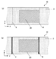
このような本発明の長尺体積ホログラム層転写箔について図を参照しながら説明する。図1は本発明の長尺体積ホログラム層転写箔の一例を示す概略断面図である。図1(a)に例示するように、本発明の長尺体積ホログラム層転写箔10は、基材1と、上記基材1上に形成され、体積ホログラムが記録された体積ホログラム層2と、上記体積ホログラム層2上に形成され、熱可塑性樹脂を含有するヒートシール層3とを有するものである。また、図1(a)に例示するように、本発明の長尺体積ホログラム積層体は長尺状に形成されたものである。
このような例において、本発明の長尺体積ホログラム層転写箔10は、上記ヒートシール層3を貫通し、かつ、上記体積ホログラム層2の少なくとも一部が切断されるように切れ込み部4が形成されていることを有することを特徴とするものである。
ここで、図1(b)は、図1(a)におけるzの方向から正視した本発明の長尺体積ホログラム層転写箔10の概略図である。図1(b)に例示するように上記切れ込み部4は、長尺体積ホログラム層転写箔10の長手方向yに対して垂直方向xの全幅に渡って形成されているものである。
Such a long volume hologram layer transfer foil of the present invention will be described with reference to the drawings. FIG. 1 is a schematic sectional view showing an example of a long volume hologram layer transfer foil of the present invention. As illustrated in FIG. 1A, a long volume hologram
In such an example, the long volume hologram
Here, FIG.1 (b) is the schematic of the elongate volume hologram
本発明によれば、上記切れ込み部が上記ヒートシール層を貫通し、かつ、上記体積ホログラム層の少なくとも一部を切断するように形成されていることにより、本発明の長尺体積ホログラム層転写箔を用いて体積ホログラム積層体を製造する際に、上記切れ込み部が形成された位置を始点として、上記基材を体積ホログラム層から剥離することにより、上記体積ホログラム層を容易に転写させることができる。
また、本発明によれば上記切れ込み部が、長手方向に対して垂直方向の全幅の少なくとも一部に形成されていることにより、上記切れ込み部をきっかけとして上記体積ホログラム層を破断することができる。このため、例えば本発明の長尺体積ホログラム層転写箔から体積ホログラム層を転写することによって体積ホログラム積層体を転写する際に、体積ホログラム層を部分的に転写させる場合であっても体積ホログラム層の箔切れ不良が生じることを防止できる。したがって、本発明によれば、被転写体への転写される体積ホログラム層の面積に関わらず、所定の面積の体積ホログラム層を連続的に転写することができる。
このようなことから、本発明によれば被転写体の所定の位置に体積ホログラムを連続的に転写することが可能な、長尺体積ホログラム層転写箔を得ることができる。
According to the present invention, the slit portion penetrates the heat seal layer and is formed so as to cut at least a part of the volume hologram layer. When the volume hologram laminate is manufactured using the above, the volume hologram layer can be easily transferred by peeling the substrate from the volume hologram layer starting from the position where the cut portion is formed. .
Further, according to the present invention, since the cut portion is formed in at least a part of the entire width in the direction perpendicular to the longitudinal direction, the volume hologram layer can be broken by using the cut portion as a trigger. Therefore, for example, when transferring the volume hologram laminate by transferring the volume hologram layer from the long volume hologram layer transfer foil of the present invention, the volume hologram layer is transferred even when the volume hologram layer is partially transferred. It is possible to prevent the occurrence of defective foil cutting. Therefore, according to the present invention, a volume hologram layer having a predetermined area can be continuously transferred regardless of the area of the volume hologram layer transferred to the transfer target.
For this reason, according to the present invention, it is possible to obtain a long volume hologram layer transfer foil capable of continuously transferring a volume hologram to a predetermined position of a transfer target.
本発明の長尺体積ホログラム層転写箔は、少なくとも基材と、体積ホログラム層と、ヒートシール層とを有するものであり、必要に応じて「5.その他の層」の項で後述する層や「6.偽造防止切れ込み部前駆体」の項で後述する偽造防止切れ込み部前駆体が用いられてもよいものである。
以下、本発明の長尺体積ホログラム層転写箔に用いられる各構成について順に説明する。
The long volume hologram layer transfer foil of the present invention has at least a base material, a volume hologram layer, and a heat seal layer. If necessary, a layer described later in the section of “5. The anti-counterfeit notch precursor described later in “6. Anti-counterfeit notch precursor” may be used.
Hereafter, each structure used for the long volume hologram layer transfer foil of this invention is demonstrated in order.
1.切れ込み部
まず、本発明の長尺体積ホログラム層転写箔に形成された切れ込み部について説明する。本発明における切れ込み部は、本発明の長尺体積ホログラム層転写箔の長手方向に対して垂直方向の全幅の少なくとも一部に、後述するヒートシール層を貫通し、かつ、後述する体積ホログラム層の少なくとも一部が切断されるように形成されたものである。
以下、このような切れ込み部について詳細に説明する。
1. Cut portion First, the cut portion formed in the long volume hologram layer transfer foil of the present invention will be described. The notch in the present invention penetrates through the heat seal layer described later at least part of the full width in the direction perpendicular to the longitudinal direction of the long volume hologram layer transfer foil of the present invention, and the volume hologram layer described later. It is formed so that at least a part is cut.
Hereinafter, such a cut portion will be described in detail.
(1)厚み方向の形成態様
まず、本発明の長尺体積ホログラム層転写箔の厚み方向に対して切れ込み部が形成されている態様について説明する。厚み方向を基準とした場合、本発明における切れ込み部は、後述するヒートシール層を貫通し、かつ、後述する体積ホログラム層の少なくとも一部が切断されるように形成されたものである。
(1) Forming Mode in the Thickness Direction First, a mode in which a cut portion is formed in the thickness direction of the long volume hologram layer transfer foil of the present invention will be described. When the thickness direction is used as a reference, the cut portion in the present invention is formed so as to penetrate the heat seal layer described later and to cut at least a part of the volume hologram layer described later.
本発明において切れ込み部が厚み方向に形成されている態様としては、後述するヒートシール層を貫通し、かつ、少なくとも体積ホログラム層の少なくとも一部が切断されるように形成されている態様であれば特に限定されるものではない。なかでも本発明においては、少なくとも体積ホログラム層の1/3以上を切断するように形成されていることが好ましく、特に1/2以上を切断するように形成されていることが好ましい。切れ込み部がこのように形成されていることにより、本発明の長尺体積ホログラム層転写箔から体積ホログラム層を転写させて体積ホログラム積層体を製造する際に、体積ホログラム層の破断不良が生じることをより効果的に防止できるからである。
さらに本発明においては切れ込み部が体積ホログラム層を完全に切断するように形成されていることが最も好ましい。これにより本発明の長尺体積ホログラム層転写箔を用いて体積ホログラム積層体を製造する際に、体積ホログラム層の切断不良が問題になることが無くなるからである。
In the present invention, the cut portion is formed in the thickness direction as long as it penetrates the heat seal layer described later and at least a portion of the volume hologram layer is cut. It is not particularly limited. In particular, in the present invention, it is preferably formed so as to cut at least 1/3 or more of the volume hologram layer, and particularly preferably formed so as to cut 1/2 or more. By forming the cut portion in this way, when the volume hologram layer is transferred from the long volume hologram layer transfer foil of the present invention to produce a volume hologram laminate, the volume hologram layer may fail to break. It is because it can prevent more effectively.
Further, in the present invention, it is most preferable that the cut portion is formed so as to completely cut the volume hologram layer. This is because, when a volume hologram laminate is manufactured using the long volume hologram layer transfer foil of the present invention, a defective cutting of the volume hologram layer does not become a problem.
また、本発明の長尺体積ホログラム層転写箔において後述する基材と体積ホログラム層との間に「5.その他の層」の項で後述する層(以下、この項において「その他の層」とする)が用いられている場合、切れ込み部は当該その他の層を切断するように形成されていてもよく、あるいは、切断しないように形成されていてもよい。切れ込み部が上記その他の層を切断するように形成されている場合、その態様としては少なくとも一部のみが切断されるように形成されている態様であってもよく、あるいは、完全に切断されるように形成されている態様であってもよい。
より具体的には、後述するように本発明の長尺体積ホログラム層転写箔は、基材と体積ホログラム層との間に剥離性保護層が形成されていることが好ましいものであるが、このような場合において、切れ込み部が形成されている態様としては、剥離性保護層の少なくとも一部または全部が切断されている態様であってもよく、あるいは、剥離性保護層は全く切断されていない態様であってもよい。
In the long volume hologram layer transfer foil of the present invention, a layer described later in the section of “5. Other layers” (hereinafter referred to as “other layers” in this section) between the substrate and volume hologram layer described later. Is used, the cut portion may be formed so as to cut the other layer, or may be formed so as not to cut. When the cut portion is formed so as to cut the other layers, it may be a mode in which at least a part of the cut portion is cut or completely cut. The aspect currently formed may be sufficient.
More specifically, as described later, the long volume hologram layer transfer foil of the present invention preferably has a peelable protective layer formed between the substrate and the volume hologram layer. In such a case, the aspect in which the cut portion is formed may be an aspect in which at least a part or all of the peelable protective layer is cut, or the peelable protective layer is not cut at all. An aspect may be sufficient.
なお、本発明における切れ込み部は後述する基材の一部が切断されるように形成されていてもよいが、基材が切断されないように形成されていることが好ましい。本発明の長尺体積ホログラム層転写箔は、連続的に体積ホログラム層を転写させることによって体積ホログラム積層体を製造するために好適に用いられるものであるため、上記基材の一部に切れ込み部が形成されていると、体積ホログラム層を転写させる際に基材が破断してしまい、体積ホログラム層の連続的な転写が困難になる可能性があるからである。 In addition, although the cut | notch part in this invention may be formed so that a part of base material mentioned later may be cut | disconnected, it is preferable that it is formed so that a base material may not be cut | disconnected. Since the long volume hologram layer transfer foil of the present invention is suitably used for producing a volume hologram laminate by continuously transferring a volume hologram layer, a cut portion is formed in a part of the substrate. This is because, when the volume hologram layer is transferred, the base material is broken when transferring the volume hologram layer, which may make it difficult to continuously transfer the volume hologram layer.
(2)面内方向の形成態様
次に、本発明の長尺体積ホログラム層転写箔の面内方向に対して切れ込み部が形成されている態様について説明する。面内方向を基準とした場合、本発明における切れ込み部は、長尺体積ホログラム層転写箔の長手方向に対して垂直方向の全幅の少なくとも一部に形成されたものである。ここで、「長手方向に対して垂直方向」とは、厳密に垂直である場合の他、切れ込み部の機能を奏し得る範囲内で略垂直である場合も含むものとする。
(2) Forming Mode in In-Plane Direction Next, a mode in which a cut portion is formed in the in-plane direction of the long volume hologram layer transfer foil of the present invention will be described. When the in-plane direction is used as a reference, the cut portion in the present invention is formed in at least a part of the full width in the direction perpendicular to the longitudinal direction of the long volume hologram layer transfer foil. Here, the term “perpendicular to the longitudinal direction” includes not only strictly perpendicular but also the case of being substantially perpendicular within the range in which the function of the cut portion can be achieved.
本発明において切れ込み部が面内方向に形成されている態様としては、長尺体積ホログラム層転写箔の長手方向に対して垂直方向の全幅の少なくとも一部に形成された態様であれば特に限定されるものではない。図2は、上記切れ込み部が形成された態様の一例を示す概略図である。上記切れ込み部が全幅の少なくとも一部に形成された態様としては、図2(a)に例示するように、本発明における長尺体積ホログラム層転写箔10において、切れ込み部4が、全幅の両端を含まずに形成された態様や、図2(b)に例示するように、切れ込み部4が全幅の両端のうち片方の端部から全幅の途中まで形成された態様、図2(c)に例示するように、切れ込み部4が全幅に渡って形成された態様を挙げることができる。本発明においては中でも、全幅に渡って形成された態様であることが好ましい。全幅に渡って形成された態様とすることにより、箔切れ不良を防止するためにより効果的であるからである。また、必要に応じてこれらの態様を組み合わせて用いることもできる。
In the present invention, the aspect in which the cut portion is formed in the in-plane direction is particularly limited as long as it is an aspect formed in at least a part of the full width in the direction perpendicular to the longitudinal direction of the long volume hologram layer transfer foil. It is not something. FIG. 2 is a schematic diagram illustrating an example of an aspect in which the cut portion is formed. As an aspect in which the cut portion is formed in at least a part of the full width, as illustrated in FIG. 2A, in the long volume hologram
さらに、上記切れ込み部は、直線状に形成された態様であってもよく、あるいは、曲線状または屈曲線状に形成された態様であってもよい。本発明においてはこれらのいずれの態様であっても好適に用いることができるが、なかでも直線状に形成された態様であることが好ましい。切れ込み部が直線状に形成されていることにより、切れ込み部を所定の位置に形成することが容易になるからである。また、直線状に形成されていることにより、体積ホログラム層の破断不良が生じることをより効果的に防止することができるからである。 Further, the cut portion may be formed in a linear shape, or may be formed in a curved shape or a bent line shape. In the present invention, any of these embodiments can be suitably used, but in particular, an embodiment formed linearly is preferable. This is because the cut portion is formed in a predetermined position by forming the cut portion in a straight line. Moreover, it is because it can prevent more effectively that the volume hologram layer breaks badly by being formed linearly.
切れ込み部が直線状に形成されている態様としては、本発明の長尺体積ホログラム層転写箔を用いて体積ホログラム層が転写される被転写体の形状等に応じて、体積ホログラム層を転写する際に、体積ホログラム層が破断される始点となるような態様であれば特に限定されるものではない。このような態様としては例えば、実線状に形成された態様や、点線状に形成された態様等を挙げることができる。本発明においてはこれらのいずれの態様であっても好適に用いることができる。また、必要に応じてこれらの態様を組み合わせて用いることもできる。 As an aspect in which the cut portion is formed in a straight line shape, the volume hologram layer is transferred according to the shape of the transfer target body onto which the volume hologram layer is transferred using the long volume hologram layer transfer foil of the present invention. In this case, there is no particular limitation as long as the volume hologram layer is a starting point at which the volume hologram layer is broken. Examples of such a mode include a mode formed in a solid line, a mode formed in a dotted line, and the like. In the present invention, any of these embodiments can be suitably used. Moreover, these aspects can also be used in combination as necessary.
切れ込み部が実線状あるいは点線状に形成されている場合は、本発明における切れ込み部は複線状に形成されていることが好ましい。これにより、例えば、本発明の長尺体積ホログラム層転写箔を用いて、被転写体へ体積ホログラム層を転写する際に、被転写体を配置する位置精度にバラツキが生じたとしても、体積ホログラム層の転写性が損なわれることを防止できるからである。さらに、上記切れ込み部が複線状に形成されることにより、複線状の切れ込み部のうちの一部の切れ込み部が、転写の際、被転写体に転写され、「B.体積ホログラム積層体」の「3.偽造防止切れ込み部」の項で後述する偽造防止切れ込み部となる。これにより、例えば、本発明の長尺体積ホログラム層転写箔を転写して製造される体積ホログラム積層体は、上記偽造防止切れ込み部を有することになる。上記体積ホログラム積層体の被転写体から体積ホログラム層を剥がそうとした場合、上記偽造防止切れ込み部が起点となって、体積ホログラム層が破壊されやすくなり、偽造防止の効果を得ることが可能となる。なお、本発明において切れ込み部が「複線状に形成されている」とは、互いに平行な複数の直線状の切れ込み部が一組となって形成されている、または互いに略平行な複数の直線状の切れ込み部が一組となって形成されていることを意味するものである。 When the cut portion is formed in a solid line shape or a dotted line shape, the cut portion in the present invention is preferably formed in a double line shape. As a result, for example, when the volume hologram layer is transferred to the transfer object using the long volume hologram layer transfer foil of the present invention, even if the positional accuracy of arranging the transfer object varies, the volume hologram This is because the transferability of the layer can be prevented from being impaired. Further, by forming the cut portion in a double-line shape, a part of the double-line cut portion is transferred to the transfer target during transfer, and the "B. Volume hologram laminate" It becomes a forgery prevention notch described later in the section of “3. Thereby, for example, the volume hologram laminate produced by transferring the long volume hologram layer transfer foil of the present invention has the forgery prevention cut portion. When the volume hologram layer is to be peeled off from the transfer body of the volume hologram laminate, the forgery prevention notch is the starting point, the volume hologram layer is easily destroyed, and the effect of preventing forgery can be obtained. Become. In the present invention, the notches are “formed in double lines” means that a plurality of straight notches parallel to each other are formed as a set, or a plurality of straight notches substantially parallel to each other. This means that the cut portions are formed as a set.
ここで、本発明において切れ込み部が複線状に形成されていることにより、被転写体へ体積ホログラム層を転写する際に、被転写体を配置する位置精度にバラツキが生じたとしても、体積ホログラム層の転写性が損なわれることを防止できる理由について図を参照しながら具体的に説明する。図3は本発明の長尺体積ホログラム層転写箔の好適な使用態様の一例を示す概略図である。図3(a)に例示するように、本発明の長尺体積ホログラム層転写箔の好適な使用態様の一つとして、被転写体20を、被転写体20の端部が上記切れ込み部4に一致するように配置した後、体積ホログラム層(図示せず)を被転写体20へ転写する態様を挙げることができる。このとき、図3(a)に例示するように切れ込み部4が単線状に形成されていると、切れ込み部4と被転写体20の端部とを一致させるには高度の位置制御が要求されることになる。そして、被転写体20を配置する位置にバラツキが生じ、被転写体20の端部が上記切れ込み部4とずれた位置に配置されると、体積ホログラム層を転写する始点がずれてしまうため、体積ホログラム層の転写性が損なわれてしまうおそれがある。
しかしながら、図3(b)に例示するように、切れ込み部4が複線状に形成されていると、被転写体20が配置される位置にバラツキが生じたとしても、複線状に形成されたいずれかの切れ込み部4に被転写体20の端部が一致するように配置することができる。このため、被転写体を配置する位置精度にバラツキが生じたとしても、体積ホログラム層の転写性が損なわれることを防止できるのである。
Here, since the notches are formed in a double-line shape in the present invention, even if there is a variation in the position accuracy of the transfer object when transferring the volume hologram layer to the transfer object, the volume hologram The reason why the transferability of the layer can be prevented from being impaired will be specifically described with reference to the drawings. FIG. 3 is a schematic view showing an example of a preferred usage mode of the long volume hologram layer transfer foil of the present invention. As illustrated in FIG. 3A, as one of the preferable usage modes of the long volume hologram layer transfer foil of the present invention, the transferred
However, as illustrated in FIG. 3B, when the
本発明において、切れ込み部が複線状に形成されている態様としては、例えば、複数の実線状の切れ込み部が一組となって形成されている態様や、複数の点線状の切れ込み部が一組となって形成されている態様や、実線状の切れ込み部と点線状の切れ込み部と一組となって形成されている態様等を挙げることができる。本発明においてはこれらのいずれの態様であっても好適に用いることができる。 In the present invention, as an aspect in which the cut portion is formed in a double line shape, for example, a mode in which a plurality of solid line cut portions are formed as a set, or a set of a plurality of dotted line cut portions. The aspect currently formed, the aspect currently formed as a set with a solid line-like cut part and a dotted line-like cut part, etc. can be mentioned. In the present invention, any of these embodiments can be suitably used.
ここで、切れ込み部が複線状に形成されている態様が、複数の点線状の切れ込み部が一組となって形成されている態様である場合、被転写体へ体積ホログラム層を転写する際に、被転写体を配置する位置精度にバラツキが生じたとしても、体積ホログラム層の転写性が損なわれることをさらに防止できる。その理由について、図を参照しながら説明する。
図4は、上記切れ込み部が複数の点線状の切れ込み部が一組となって形成されている場合の利点を説明する概略図である。上述したように、本発明の長尺体積ホログラム層転写箔の好適な使用態様の一つとして、被転写体の端部が上記切れ込み部に一致するように配置した後、体積ホログラム層を被転写体へ転写する態様を挙げることができる。このような態様においては、図4(a)に例示するように、被転写体20の端部が、切れ込み部4に対して斜めに配置されてしまった場合、実線状の切れ込み部4の場合は、体積ホログラム層を転写する際に切れ込み部4が形成されていない部位が破断されることになるため、体積ホログラム層の破断不良が生じてしまう可能性がある。
しかしながら、図4(b)に例示するように切れ込み部4が複数の点線状の切れ込み部が一組となって形成されている場合は、たとえ被転写体20の端部が、切れ込み部4に対して斜めに配置されてしまった場合であっても、隣接する切れ込み部4が互いに連結されることにより、体積ホログラム層を転写する際に切れ込み部4が形成されていない部位が破断されることを少なくすることができる。
このため、被転写体を配置する位置精度にバラツキが生じたとしても、体積ホログラム層の転写性が損なわれることを防止できるのである。
Here, when the aspect in which the cut portion is formed in a double-line shape is an embodiment in which a plurality of dotted cut portions are formed as a set, when transferring the volume hologram layer to the transfer object Even if the positional accuracy for arranging the transfer object varies, it is possible to further prevent the transferability of the volume hologram layer from being impaired. The reason will be described with reference to the drawings.
FIG. 4 is a schematic diagram for explaining an advantage in the case where the cut portion is formed as a set of a plurality of dotted cut portions. As described above, as one of the preferable usage modes of the long volume hologram layer transfer foil of the present invention, the volume hologram layer is transferred after the end of the transfer target body is arranged so as to coincide with the cut portion. Examples of transfer to the body can be given. In such an embodiment, as illustrated in FIG. 4A, when the end of the
However, as illustrated in FIG. 4B, when the
For this reason, even if the positional accuracy at which the transfer object is arranged varies, it is possible to prevent the transferability of the volume hologram layer from being impaired.
ここで、切れ込み部が複線状に形成されている態様が、複数の点線状の切れ込み部が一組となって形成されている態様である場合、一組として形成されている個々の切れ込み部の点線のピッチはすべて同一であってもよく、あるいは、異なっていてもよい。 Here, when the mode in which the cut portions are formed in a double line shape is a mode in which a plurality of dotted line cut portions are formed as a set, the individual cut portions formed as a set The pitches of the dotted lines may all be the same or different.
なお、切れ込み部が複線状に形成されている場合、一組に形成される切れ込み部の数は特に限定されるものではなく、本発明の長尺体積ホログラム層転写箔を用いて体積ホログラム層を転写する被転写体の形状等に応じて、任意に決定することができる。また、切れ込み部が複線状に形成されている場合、一組に形成された切れ込み部内における複数の切れ込み部の間隔は、0.1mm〜2mmの範囲内であることが好ましい。 When the cut portions are formed in a double-line shape, the number of cut portions formed in one set is not particularly limited, and the volume hologram layer is formed using the long volume hologram layer transfer foil of the present invention. It can be arbitrarily determined according to the shape of the transfer object to be transferred. Moreover, when the notch part is formed in double-line shape, it is preferable that the space | interval of the some notch part in the notch part formed in 1 set exists in the range of 0.1 mm-2 mm.
本発明の長尺体積ホログラム層転写箔は長尺に形成されたものであるため、通常、本発明の長尺体積ホログラム層転写箔には複数本の切れ込み部が形成されることになる。このとき、複数本の切れ込み部が形成されている態様としては特に限定されるものではなく、本発明の長尺体積ホログラム層転写箔を用いて体積ホログラム層が転写される被転写体の形状等に応じて任意の態様を用いることができる。
ここで、切れ込み部が複線状に形成されている場合、一組に形成された複数の切れ込み部をまとめて「一本」の切れ込み部と評価するものとする。
Since the long volume hologram layer transfer foil of the present invention is formed in a long shape, a plurality of cut portions are usually formed in the long volume hologram layer transfer foil of the present invention. At this time, the aspect in which a plurality of cut portions are formed is not particularly limited, and the shape of the transfer target body onto which the volume hologram layer is transferred using the long volume hologram layer transfer foil of the present invention, etc. Any embodiment can be used depending on the case.
Here, when the cut portion is formed in a double-line shape, a plurality of cut portions formed in one set are collectively evaluated as “one” cut portion.
本発明の長尺体積ホログラム層転写箔に複数本の切れ込み部が形成された態様としては、例えば、図5(a)に例示するように被転写体20の、長尺体積ホログラム層転写箔10の長手方向に垂直な端部に、切れ込み部4が一致するように形成された態様や、図5(b)に例示するように上記互いに隣接する切れ込み部4の間隔が、被転写体20の、長尺体積ホログラム層転写箔10の長手方向に平行方向の幅よりも短くなるように形成された態様等を例示することができる。
本発明においては、これらのいずれの態様であっても好適に用いることができる。
As an aspect in which a plurality of slits are formed in the long volume hologram layer transfer foil of the present invention, for example, as illustrated in FIG. A mode in which the
In the present invention, any of these embodiments can be suitably used.
また、本発明に用いられる切れ込み部は、他の切れ込み部と組み合わされて形成されたものであってもよい。切れ込み部がこのような態様で形成された例としては、例えば、本発明の長尺体積ホログラム層転写箔の長手方向に対して平行方向に形成された平行切れ込み部と組み合わされた態様を挙げることができる。このような態様で切れ込み部が形成された例としては、例えば、図6に例示するように平行切れ込み部5が、被転写体20の、長尺体積ホログラム層転写箔10の長手方向yに平行な方向の端部に一致するように形成された態様を例示することができる。
Further, the cut portion used in the present invention may be formed in combination with another cut portion. As an example in which the cut portion is formed in such a manner, for example, an embodiment combined with a parallel cut portion formed in a direction parallel to the longitudinal direction of the long volume hologram layer transfer foil of the present invention is mentioned. Can do. As an example in which the cut portion is formed in such a manner, for example, as illustrated in FIG. 6, the
2.体積ホログラム層
次に本発明に用いられる体積ホログラム層について説明する。本発明に用いられる体積ホログラム層は、体積ホログラムが記録されたものであり、本発明の長尺体積ホログラム層転写箔を用いて体積ホログラム積層体を製造する際に、被転写体へ転写されるものである。
以下、このような体積ホログラム層について詳細に説明する。
2. Volume hologram layer Next, the volume hologram layer used in the present invention will be described. The volume hologram layer used in the present invention is a volume hologram recorded, and is transferred to a transfer target when a volume hologram laminate is manufactured using the long volume hologram layer transfer foil of the present invention. Is.
Hereinafter, such a volume hologram layer will be described in detail.
(1)構成材料
本発明に用いられる体積ホログラム層を構成する材料としては、体積ホログラムを記録することができるものであれば特に限定されるものではなく、一般的に体積ホログラムに用いられる材料を任意に用いることができる。このような材料としては、例えば、銀塩材料、重クロム酸ゼラチン乳剤、光重合性樹脂、光架橋性樹脂等の公知の体積ホログラム記録材料が挙げることできるが、なかでも本発明においては、(i)バインダー樹脂、光重合可能な化合物、光重合開始剤および増感色素を含有する第1の感光材料、または、(ii)カチオン重合性化合物、ラジカル重合性化合物、光ラジカル重合開始剤系および光カチオン重合開始剤系を含有する第2の感光材料を好適に用いることができる。
以下、このような第1の感光材料および第2の感光材料について順に説明する。
(1) Constituent material The material constituting the volume hologram layer used in the present invention is not particularly limited as long as it can record a volume hologram, and a material generally used for a volume hologram is used. It can be used arbitrarily. Examples of such a material include known volume hologram recording materials such as silver salt materials, dichromated gelatin emulsions, photopolymerizable resins, and photocrosslinkable resins. i) a first photosensitive material containing a binder resin, a photopolymerizable compound, a photopolymerization initiator and a sensitizing dye, or (ii) a cationic polymerizable compound, a radical polymerizable compound, a photo radical polymerization initiator system, and A second photosensitive material containing a cationic photopolymerization initiator system can be suitably used.
Hereinafter, the first photosensitive material and the second photosensitive material will be described in order.
(i)第1の感光材料
まず、上記第1の感光材料について説明する。上述したように第1の感光材料はバインダー樹脂、光重合可能な化合物、光重合開始剤および増感色素を含有するものである。
(I) First photosensitive material First, the first photosensitive material will be described. As described above, the first photosensitive material contains a binder resin, a photopolymerizable compound, a photopolymerization initiator, and a sensitizing dye.
(バインダー樹脂)
上記バインダー樹脂としては、例えば、ポリ(メタ)アクリル酸エステル、またはその部分加水分解物、ポリ酢酸ビニルまたはその加水分解物、アクリル酸、アクリル酸エステル等の共重合可能なモノマー群の少なくとも1つを重合成分とする共重合体、またはそれらの混合物や、ポリイソプレン、ポリブタジエン、ポリクロロプレン、ポリビニルアルコールの部分アセタール化物であるポリビニルアセタール、ポリビニルブチラール、ポリ酢酸ビニル、塩化ビニル−酢酸ビニル共重合体等、またはそれらの混合物等を挙げることができる。ここで、体積ホログラム層を形成する際には、記録された体積ホログラムを安定化するために、加熱してモノマーを移動させる工程が実施される場合がある。このため、本発明に用いられるバインダー樹脂はガラス転移温度が比較的低く、モノマー移動が容易に移動できるものであることが好ましい。
(Binder resin)
Examples of the binder resin include at least one copolymerizable monomer group such as poly (meth) acrylic acid ester or a partially hydrolyzed product thereof, polyvinyl acetate or a hydrolyzed product thereof, acrylic acid, and an acrylic acid ester. As a polymerization component, or a mixture thereof, polyisoprene, polybutadiene, polychloroprene, polyvinyl acetal which is a partial acetalization product of polyvinyl alcohol, polyvinyl butyral, polyvinyl acetate, vinyl chloride-vinyl acetate copolymer, etc. Or a mixture thereof. Here, when the volume hologram layer is formed, a step of moving the monomer by heating may be performed in order to stabilize the recorded volume hologram. For this reason, it is preferable that the binder resin used in the present invention has a relatively low glass transition temperature and can easily move the monomer.
(光重合可能な化合物)
上記光重合可能な化合物としては、後述するような1分子中に少なくとも1個のエチレン性不飽和結合を有する光重合、光架橋可能なモノマー、オリゴマー、プレポリマーおよびそれらの混合物を用いることができる。具体例としては、不飽和カルボン酸およびその塩、不飽和カルボン酸と脂肪族多価アルコール化合物とのエステル、不飽和カルボン酸と脂肪族多価アミン化合物とのアミド化合物等を挙げることができる。
(Photopolymerizable compound)
As the photopolymerizable compound, there can be used photopolymerization having at least one ethylenically unsaturated bond per molecule, photocrosslinkable monomer, oligomer, prepolymer and a mixture thereof as described later. . Specific examples include unsaturated carboxylic acids and salts thereof, esters of unsaturated carboxylic acids and aliphatic polyhydric alcohol compounds, amide compounds of unsaturated carboxylic acids and aliphatic polyvalent amine compounds, and the like.
ここで、上記不飽和カルボン酸のモノマーの具体例としては、例えば、アクリル酸、メタクリル酸、イタコン酸、クロトン酸、イソクロトン酸、マレイン酸等を挙げることができる。また上記脂肪族多価アルコール化合物と不飽和カルボン酸とのエステルのモノマーの具体例としては、例えば、アクリル酸エステルとして、エチレングリコールジアクリレート、トリエチレングリコールジアクリレート、1,3−ブタンジオールジアクリレート、テトラメチレングリコールジアクリレート、プロピレングリコールジアクリレート、ネオペンチルグリコールジアクリレート、トリメチロールプロパントリアクリレート、トリメチロールプロパントリ(アクリロイルオキシプロピル)エーテル、トリメチロールエタントリアクリレート等を挙げることができる。 Here, specific examples of the unsaturated carboxylic acid monomer include acrylic acid, methacrylic acid, itaconic acid, crotonic acid, isocrotonic acid, maleic acid and the like. Specific examples of the ester monomer of the aliphatic polyhydric alcohol compound and the unsaturated carboxylic acid include, for example, acrylic acid esters such as ethylene glycol diacrylate, triethylene glycol diacrylate, and 1,3-butanediol diacrylate. , Tetramethylene glycol diacrylate, propylene glycol diacrylate, neopentyl glycol diacrylate, trimethylolpropane triacrylate, trimethylolpropane tri (acryloyloxypropyl) ether, trimethylolethane triacrylate, and the like.
上記メタクリル酸エステルとしては、テトラメチレングリコールジメタクリレート、トリエチレングリコールジメタクリレート、ネオペンチルグリコールジメタクリレート、トリメチロールプロパントリメタクリレート、トリメチロールエタントリメタクリレート等を挙げることができる。また、上記イタコン酸エステルとしてはエチレングリコールジイタコネート、プロピレングリコールジイタコネート、1,3−ブタンジオールジイタコネート等を挙げることができる。また、上記クロトン酸エステルとしては、エチレングリコールジクロトネート、テトラメチレングリコールジクロトネート、ペンタエリスリトールジクロトネート、ソルビトールテトラクロトネート等を挙げることができる。さらに上記イソクロトン酸エステルとしては、エチレングリコールジイソクロトネート、ペンタエリスリトールジイソクロトネート、ソルビトールテトライソクロトネート等を挙げることができる。さらにまた、上記マレイン酸エステルとしては、エチレングリコールジマレエート、トリエチレングリコールジマレエート、ペンタエリスリトールジマレエート、ソルビトールテトラマレエート等を挙げることができる。 Examples of the methacrylic acid ester include tetramethylene glycol dimethacrylate, triethylene glycol dimethacrylate, neopentyl glycol dimethacrylate, trimethylolpropane trimethacrylate, and trimethylolethane trimethacrylate. Examples of the itaconic acid ester include ethylene glycol diitaconate, propylene glycol diitaconate, and 1,3-butanediol diitaconate. Examples of the crotonic acid ester include ethylene glycol dicrotonate, tetramethylene glycol dicrotonate, pentaerythritol dicrotonate, and sorbitol tetracrotonate. Furthermore, examples of the isocrotonic acid ester include ethylene glycol diisocrotonate, pentaerythritol diisocrotonate, and sorbitol tetraisocrotonate. Furthermore, examples of the maleic ester include ethylene glycol dimaleate, triethylene glycol dimaleate, pentaerythritol dimaleate, and sorbitol tetramaleate.
上記ハロゲン化不飽和カルボン酸としては、2,2,3,3−テトラフルオロプロピルアクリレート、1H,1H,2H,2H−ヘプタデカフルオロデシルアクリレート、2,2,3,3−テトラフルオロプロピルメタクリレート等を挙げることができる。
また、上記不飽和カルボン酸と脂肪族多価アミン化合物とのアミドのモノマーの具体例としては、メチレンビスアクリルアミド、メチレンビスメタクリルアミド、1,6−ヘキサメチレンビスアクリルアミド、1,6−ヘキサメチレンビスメタクリルアミド等を挙げることができる。
Examples of the halogenated unsaturated carboxylic acid include 2,2,3,3-tetrafluoropropyl acrylate, 1H, 1H, 2H, 2H-heptadecafluorodecyl acrylate, 2,2,3,3-tetrafluoropropyl methacrylate, and the like. Can be mentioned.
Specific examples of the amide monomer of the unsaturated carboxylic acid and the aliphatic polyvalent amine compound include methylene bisacrylamide, methylene bismethacrylamide, 1,6-hexamethylene bisacrylamide, 1,6-hexamethylene bis. And methacrylamide.
(光重合開始剤)
本発明に用いられる光重合開始剤としては、例えば、1,3−ジ(t−ブチルジオキシカルボニル)ベンゾフェノン、3,3´,4,4´−テトラキス(t−ブチルジオキシカルボニル)ベンゾフェノン、N−フェニルグリシン、2,4,6−トリス(トリクロロメチル)−s−トリアジン、3−フェニル−5−イソオキサゾロン、2−メルカプトベンズイミダゾール、また、イミダゾール二量体類等を挙げることができる。なかでも本発明に用いられる光重合開始剤は、記録された体積ホログラムの安定化の観点から、ホログラム記録後に分解処理されるものが好ましい。例えば有機過酸化物系にあっては紫外線照射することにより容易に分解されるので好ましい。
(Photopolymerization initiator)
Examples of the photopolymerization initiator used in the present invention include 1,3-di (t-butyldioxycarbonyl) benzophenone, 3,3 ′, 4,4′-tetrakis (t-butyldioxycarbonyl) benzophenone, Examples thereof include N-phenylglycine, 2,4,6-tris (trichloromethyl) -s-triazine, 3-phenyl-5-isoxazolone, 2-mercaptobenzimidazole, and imidazole dimers. Among them, the photopolymerization initiator used in the present invention is preferably one that is decomposed after hologram recording from the viewpoint of stabilizing the recorded volume hologram. For example, organic peroxides are preferable because they are easily decomposed by irradiation with ultraviolet rays.
(増感色素)
本発明に用いられる増感色素としては、チオピリリウム塩系色素、メロシアニン系色素、キノリン系色素、スチリルキノリン系色素、ケトクマリン系色素、チオキサンテン系色素、キサンテン系色素、オキソノール系色素、シアニン染料、ローダミン染料、チオピリリウム塩系色素、ピリリウムイオン系色素、ジフェニルヨードニウムイオン系色素等を挙げることができる。
(Sensitizing dye)
Sensitizing dyes used in the present invention include thiopyrylium salt dyes, merocyanine dyes, quinoline dyes, styrylquinoline dyes, ketocoumarin dyes, thioxanthene dyes, xanthene dyes, oxonol dyes, cyanine dyes, rhodamines. And dyes, thiopyrylium salt dyes, pyrylium ion dyes, diphenyliodonium ion dyes, and the like.
(ii)第2の感光材料
次に、本発明に用いられる第2の感光材料について説明する。上述したように第2の感光材料は、カチオン重合性化合物、ラジカル重合性化合物、光ラジカル重合開始剤系、および、カチオン重合開始剤系を含有するものである。
(Ii) Second Photosensitive Material Next, the second photosensitive material used in the present invention will be described. As described above, the second photosensitive material contains a cationic polymerizable compound, a radical polymerizable compound, a photo radical polymerization initiator system, and a cationic polymerization initiator system.
ここで、このような第2感光材料が用いられる場合、体積ホログラム層に体積ホログラムが記録する方法としては、光ラジカル重合開始剤系が感光するレーザー光等の光を照射し、次いで、光カチオン重合開始剤系が感光する上記レーザー光とは別の波長の光を照射する方法が用いられることになる。 Here, when such a second photosensitive material is used, the volume hologram is recorded on the volume hologram layer by irradiating light such as a laser beam that is exposed to a photo radical polymerization initiator system, A method of irradiating light having a wavelength different from that of the laser light that the polymerization initiator system is sensitive to will be used.
(カチオン重合性化合物)
上記カチオン重合性化合物としては、ラジカル重合性化合物の重合が比較的低粘度の組成物中で行われることが好ましいという点から、室温で液状のものが好適に用いられる。このようなカチオン重合性化合物としては、例えば、ジグリセロールジエーテル、ペンタエリスリトールポリジグリシジルエーテル、1,4−ビス(2,3−エポキシプロポキシパーフルオロイソプロピル)シクロヘキサン、ソルビトールポリグリシジルエーテル、1,6−ヘキサンジオールグリシジルエーテル、ポリエチレングリコールジグリシジルエーテル、フェニルグリシジルエーテル等を挙げることができる。
(Cationically polymerizable compound)
As the cationic polymerizable compound, a liquid compound at room temperature is preferably used because it is preferable that the polymerization of the radical polymerizable compound is performed in a composition having a relatively low viscosity. Examples of such cationically polymerizable compounds include diglycerol diether, pentaerythritol polydiglycidyl ether, 1,4-bis (2,3-epoxypropoxyperfluoroisopropyl) cyclohexane, sorbitol polyglycidyl ether, 1,6- Examples thereof include hexanediol glycidyl ether, polyethylene glycol diglycidyl ether, and phenyl glycidyl ether.
(ラジカル重合性化合物)
上記ラジカル重合性化合物としては、分子中に少なくとも1つのエチレン性不飽和二重結合を有するものが好ましい。また、本発明に用いられるラジカル重合性化合物の平均屈折率は、上記カチオン重合性化合物の平均屈折率より大きいことが好ましく、なかでも0.02以上大きいことが好ましい。これは、ラジカル重合性化合物とカチオン重合性化合物との屈折率の差によって、体積ホログラムが形成されることによるものである。したがって、平均屈折率の差が上記値以下である場合には、屈折率変調が不十分となるからである。本発明に用いられるラジカル重合性化合物としては、例えば、アクリルアミド、メタクリルアミド、スチレン、2−ブロモスチレン、フェニルアクリレート、2−フェノキシエチルアクリレート、2,3−ナフタレンジカルボン酸(アクリロキシエチル)モノエステル、メチルフェノキシエチルアクリレート、ノニルフェノキシエチルアクリレート、β−アクリロキシエチルハイドロゲンフタレート等を挙げることができる。
(Radically polymerizable compound)
As the radical polymerizable compound, those having at least one ethylenically unsaturated double bond in the molecule are preferable. The average refractive index of the radical polymerizable compound used in the present invention is preferably larger than the average refractive index of the cationic polymerizable compound, and more preferably 0.02 or more. This is because a volume hologram is formed by the difference in refractive index between the radical polymerizable compound and the cationic polymerizable compound. Therefore, when the average refractive index difference is not more than the above value, the refractive index modulation becomes insufficient. Examples of the radical polymerizable compound used in the present invention include acrylamide, methacrylamide, styrene, 2-bromostyrene, phenyl acrylate, 2-phenoxyethyl acrylate, 2,3-naphthalenedicarboxylic acid (acryloxyethyl) monoester, Examples thereof include methylphenoxyethyl acrylate, nonylphenoxyethyl acrylate, and β-acryloxyethyl hydrogen phthalate.
(光ラジカル重合開始剤系)
本発明に用いられる光ラジカル重合開始剤系としては、体積ホログラムを記録する際に、第1露光によって活性ラジカルを生成し、該活性ラジカルがラジカル重合性化合物を重合させることができるものであれば特に限定されるものではない。また、一般に光を吸収する成分である増感剤と活性ラジカル発生化合物や酸発生化合物を組み合わせて用いてもよい。このような光ラジカル重合開始剤系における増感剤は可視レーザー光を吸収するために色素のような有色化合物が用いられる場合が多いが、無色透明ホログラムとする場合には、シアニン系色素の使用が好ましい。シアニン系色素は一般に光によって分解しやすいため、本発明における後露光、または室内光や太陽光の下に数時間から数日放置することでホログラム中の色素が分解されて可視域に吸収を持たなくなり、無色透明な体積ホログラムを得ることができるからである。
(Photo radical polymerization initiator system)
As the radical photopolymerization initiator system used in the present invention, any active radical can be generated by the first exposure when the volume hologram is recorded, and the active radical can polymerize the radical polymerizable compound. It is not particularly limited. Moreover, you may use combining the sensitizer which is a component which generally absorbs light, an active radical generating compound, and an acid generating compound. A sensitizer in such a radical photopolymerization initiator system often uses a colored compound such as a dye to absorb visible laser light, but in the case of a colorless transparent hologram, a cyanine dye is used. Is preferred. Since cyanine dyes are generally easily decomposed by light, the dyes in the hologram are decomposed and absorbed in the visible range by being left exposed for several hours to several days under post-exposure or indoor light or sunlight in the present invention. This is because a colorless and transparent volume hologram can be obtained.
上記シアニン系色素の具体例としては、アンヒドロ−3,3´−ジカルボキシメチル−9−エチル−2,2´チアカルボシアニンベタイン、アンヒドロ−3−カルボキシメチル−3´,9´−ジエチル−2,2´チアカルボシアニンベタイン、3,3´,9−トリエチル−2,2´−チアカルボシアニン・ヨウ素塩、3,9−ジエチル−3´−カルボキシメチル−2,2´−チアカルボシアニン・ヨウ素塩、3,3´,9−トリエチル−2,2´−(4,5,4´,5´−ジベンゾ)チアカルボシアニン・ヨウ素塩、2−[3−(3−エチル−2−ベンゾチアゾリデン)−1−プロペニル]−6−[2−(3−エチル−2−ベンゾチアゾリデン)エチリデンイミノ]−3−エチル−1,3,5−チアジアゾリウム・ヨウ素塩、2−[[3−アリル−4−オキソ−5−(3−n−プロピル−5,6−ジメチル−2−ベンゾチアゾリリデン)−エチリデン−2−チアゾリニリデン]メチル]3−エチル−4,5−ジフェニルチアゾリニウム・ヨウ素塩、1,1´,3,3,3´,3´−ヘキサメチル−2,2´−インドトリカルボシアニン・ヨウ素塩、3,3´−ジエチル−2,2´−チアトリカルボシアニン・過塩素酸塩、アンヒドロ−1−エチル−4−メトキシ−3´−カルボキシメチル−5´−クロロ−2,2´−キノチアシアニンベタイン、アンヒドロ−5,5´−ジフェニル−9−エチル−3,3´−ジスルホプロピルオキサカルボシアニンヒドロキシド・トリエチルアミン塩等が挙げられ、これらの1種または2種以上を組み合わせて使用することができる。 Specific examples of the cyanine dye include anhydro-3,3′-dicarboxymethyl-9-ethyl-2,2′thiacarbocyanine betaine, anhydro-3-carboxymethyl-3 ′, 9′-diethyl-2. , 2 'thiacarbocyanine betaine, 3,3', 9-triethyl-2,2'-thiacarbocyanine iodine salt, 3,9-diethyl-3'-carboxymethyl-2,2'-thiacarbocyanine Iodine salt, 3,3 ′, 9-triethyl-2,2 ′-(4,5,4 ′, 5′-dibenzo) thiacarbocyanine iodine salt, 2- [3- (3-ethyl-2-benzo Thiazolidene) -1-propenyl] -6- [2- (3-ethyl-2-benzothiazolidene) ethylideneimino] -3-ethyl-1,3,5-thiadiazolium iodine salt, 2- [[3-Allyl-4 Oxo-5- (3-n-propyl-5,6-dimethyl-2-benzothiazolidene) -ethylidene-2-thiazolinylidene] methyl] 3-ethyl-4,5-diphenylthiazolinium-iodine salt, 1 , 1 ', 3,3,3', 3'-hexamethyl-2,2'-indotricarbocyanine / iodine salt, 3,3'-diethyl-2,2'-thiatricarbocyanine / perchlorate Anhydro-1-ethyl-4-methoxy-3'-carboxymethyl-5'-chloro-2,2'-quinothiocyanine betaine, anhydro-5,5'-diphenyl-9-ethyl-3,3'- Examples thereof include disulfopropyloxacarbocyanine hydroxide and triethylamine salts, and one or more of these can be used in combination.
上記活性ラジカル発生化合物としては、例えば、ジアリールヨードニウム塩類、あるいは2,4,6−置換−1,3,5−トリアジン類が挙げられる。高い感光性が必要なときは、ジアリールヨードニウム塩類の使用が特に好ましい。上記ジアリールヨードニウム塩類の具体例としては、ジフェニルヨードニウム、4,4´−ジクロロジフェニルヨードニウム、4,4´−ジメトキシジフェニルヨードニウム、4,4´−ジターシャリーブチルジフェニルヨードニウム、3,3´−ジニトロジフェニルヨードニウムなどのクロリド、ブロミド、テトラフルオロボレート、ヘキサフルオロホスフェート、ヘキサフルオロアルセネート、ヘキサフルオロアンチモネート、トリフルオロメタンスルホン酸塩、9,10−ジメトキシアントラセン−2−スルホン酸塩などが例示される。又2,4,6−置換−1,3,5−トリアジン類の具体例としては、2−メチル−4,6−ビス(トリクロロメチル)ー1,3,5−トリアジン、2,4,6−トリス(トリクロロメチル)−1,3,5−トリアジン、2−フェニル−4,6−ビス(トリクロロメチル)−1,3,5−トリアジン、2,4−ビス(トリクロロメチル)−6−(p−メトキシフェニルビニル)−1,3,5−トリアジン、2−(4´−メトキシ−1´−ナフチル)−4,6−ビス(トリクロロメチル)−1,3,5−トリアジン等が挙げられる。 Examples of the active radical generating compound include diaryliodonium salts and 2,4,6-substituted-1,3,5-triazines. The use of diaryliodonium salts is particularly preferred when high photosensitivity is required. Specific examples of the diaryl iodonium salts include diphenyl iodonium, 4,4′-dichlorodiphenyl iodonium, 4,4′-dimethoxydiphenyl iodonium, 4,4′-ditertiary butyl diphenyl iodonium, 3,3′-dinitrodiphenyl iodonium. Such as chloride, bromide, tetrafluoroborate, hexafluorophosphate, hexafluoroarsenate, hexafluoroantimonate, trifluoromethanesulfonate, 9,10-dimethoxyanthracene-2-sulfonate, and the like. Specific examples of 2,4,6-substituted-1,3,5-triazines include 2-methyl-4,6-bis (trichloromethyl) -1,3,5-triazine, 2,4,6 -Tris (trichloromethyl) -1,3,5-triazine, 2-phenyl-4,6-bis (trichloromethyl) -1,3,5-triazine, 2,4-bis (trichloromethyl) -6- ( p-methoxyphenylvinyl) -1,3,5-triazine, 2- (4′-methoxy-1′-naphthyl) -4,6-bis (trichloromethyl) -1,3,5-triazine and the like. .
(光カチオン重合開始剤系)
本発明に用いられる光カチオン重合開始剤系としは、体積ホログラムが記録される際の第1露光に対しては低感光性で、第1露光と異なる波長の光を照射する後露光に感光してブレンステッド酸あるいはルイス酸を発生し、カチオン重合性化合物を重合させるような開始剤系であれば特に限定されるものではない。なかでも本発明においては第1露光の間はカチオン重合性化合物を重合させないものが用いられることが特に好ましい。このような光カチオン重合開始剤系としては、例えばジアリールヨードニウム塩類、トリアリールスルホニウム塩類、鉄アレン錯体類等が挙げられる。ジアリールヨードニウム塩類で好ましいものとしては上述した光ラジカル重合開始剤系で示したヨードニウムのテトラフルオロボレート、ヘキサフルオロホスフェート、ヘキサフルオロアルセネート、ヘキサフルオロアンチモネートなどが挙げられる。トリアリールスルホニウム塩類で好ましいものとしては、トリフェニルスルホニウム、4−ターシャリーブチルトリフェニルスルホニウム等が挙げられる。
(Photocationic polymerization initiator system)
The cationic photopolymerization initiator system used in the present invention has low photosensitivity for the first exposure when a volume hologram is recorded, and is sensitive to post-exposure by irradiating light having a wavelength different from that of the first exposure. The initiator system is not particularly limited as long as it generates a Bronsted acid or a Lewis acid and polymerizes a cationically polymerizable compound. In particular, in the present invention, it is particularly preferable to use a compound that does not polymerize the cationic polymerizable compound during the first exposure. Examples of such a cationic photopolymerization initiator system include diaryliodonium salts, triarylsulfonium salts, iron allene complexes, and the like. Preferable diaryliodonium salts include iodonium tetrafluoroborate, hexafluorophosphate, hexafluoroarsenate, hexafluoroantimonate and the like shown in the radical photopolymerization initiator system described above. Preferable triarylsulfonium salts include triphenylsulfonium, 4-tertiarybutyltriphenylsulfonium, and the like.
(その他)
第2の感光材料には、必要に応じてバインダー樹脂、熱重合防止剤、シランカップリング剤、可塑剤、着色料等を併用してもよい。バインダー樹脂は、ホログラム形成前の組成物の成膜性、膜厚の均一性を改善する場合や、レーザー光等の光の照射による重合で形成された干渉縞を後露光までの間、安定に存在させるために使用される。バインダー樹脂は、カチオン重合性化合物やラジカル重合性化合物と相溶性のよいものであればよく、例えば塩素化ポリエチレン、ポリメチルメタクリレート、メチルメタクリレートと他の(メタ)アクリル酸アルキルエステルとの共重合体、塩化ビニルとアクリロニトリルの共重合体、ポリ酢酸ビニル等が挙げられる。バインダー樹脂は、その側鎖又は主鎖にカチオン重合性基等の反応性を有していてもよい。
(Other)
In the second photosensitive material, a binder resin, a thermal polymerization inhibitor, a silane coupling agent, a plasticizer, a colorant, and the like may be used in combination as necessary. The binder resin is used to improve the film formability and film thickness uniformity of the composition before hologram formation, and to stabilize interference fringes formed by polymerization by irradiation with light such as laser light until post-exposure. Used to make it exist. The binder resin only needs to be compatible with the cationic polymerizable compound or the radical polymerizable compound. For example, a copolymer of chlorinated polyethylene, polymethyl methacrylate, methyl methacrylate and other alkyl (meth) acrylates. And a copolymer of vinyl chloride and acrylonitrile, polyvinyl acetate, and the like. The binder resin may have reactivity such as a cation polymerizable group in its side chain or main chain.
(2)その他
本発明に用いられる体積ホログラム層の厚みは、所定の体積ホログラム層を形成することができる範囲内であれば特に限定されるものではなく、上述した構成材料の種類に応じて適宜調整することができる。なかでも本発明に用いられる体積ホログラム層の厚みは、1μm〜50μmの範囲内であることが好ましく、特に3μm〜25μmの範囲内であることが好ましい。
なお、本発明においては体積ホログラム層の少なくとも一部を切断するように上記切れ込み部が形成されていることから、厚みに関わらず転写特性の良好な体積ホログラム層を得ることができる。
(2) Others The thickness of the volume hologram layer used in the present invention is not particularly limited as long as it is within a range in which a predetermined volume hologram layer can be formed, and is appropriately determined according to the type of the constituent material described above. Can be adjusted. In particular, the thickness of the volume hologram layer used in the present invention is preferably in the range of 1 μm to 50 μm, and particularly preferably in the range of 3 μm to 25 μm.
In the present invention, since the cut portion is formed so as to cut at least a part of the volume hologram layer, a volume hologram layer having good transfer characteristics can be obtained regardless of the thickness.
3.ヒートシール層
次に本発明に用いられるヒートシール層について説明する。本発明に用いられるヒートシール層は熱可塑性樹脂を含有するものであり、本発明の長尺体積ホログラム層転写箔を用いて体積ホログラム積層体を製造する際に、体積ホログラム層と被転写体とを接着させる機能を有するものである。
以下、本発明に用いられるヒートシール層について詳細に説明する。
3. Next, the heat seal layer used in the present invention will be described. The heat seal layer used in the present invention contains a thermoplastic resin, and when producing a volume hologram laminate using the long volume hologram layer transfer foil of the present invention, a volume hologram layer, a transferred object, Has a function of adhering.
Hereinafter, the heat seal layer used in the present invention will be described in detail.
本発明に用いられる熱可塑性樹脂としては、本発明の長尺体積ホログラム層転写箔から体積ホログラム層が転写される被転写体の種類に応じて、体積ホログラム層と被転写体とを接着できるものであれば特に限定されるものではない。このような熱可塑性樹脂としては、例えば、エチレン−酢酸ビニル共重合樹脂、塩化ビニル−酢酸ビニル共重合樹脂、ポリアミド樹脂、ポリエステル樹脂、ポリエチレン樹脂、エチレン−イソブチルアクリレート共重合樹脂、ブチラール樹脂、ポリ酢酸ビニルおよびその共重合体樹脂、アイオノマー樹脂、酸変性ポリオレフィン系樹脂、アクリル系・メタクリル系などの(メタ)アクリル系樹脂、アクリル酸エステル系樹脂、エチレン・(メタ)アクリル酸共重合体、エチレン・(メタ)アクリル酸エステル共重合体、ポリメチルメタクリレート系樹脂、セルロース系樹脂、ポリビニルエーテル系樹脂、ポリウレタン樹脂、ポリカーボネート樹脂、ポリプロピレン樹脂、エポキシ樹脂、フェノール樹脂、ビニル系樹脂、マレイン酸樹脂、アルキッド樹脂、ポリエチレンオキサイド樹脂、ユリア樹脂、メラミン樹脂、メラミン・アルキッド樹脂、シリコーン樹脂、ゴム系樹脂、スチレンブタジエンスチレンブロック共重合体(SBS)、スチレンイソプレンスチレンブロック共重合体(SIS)、スチレンエチレンブチレンスチレンブロック共重合体(SEBS)、スチレンエチレンプロピレンスチレンブロック共重合体(SEPS)等を挙げることができる。本発明においてはこれらのいずれの熱可塑性樹脂であっても好適に用いることができる。 As the thermoplastic resin used in the present invention, a volume hologram layer and a transfer target can be bonded in accordance with the type of transfer target to which the volume hologram layer is transferred from the long volume hologram layer transfer foil of the present invention. If it is, it will not specifically limit. Examples of such thermoplastic resins include ethylene-vinyl acetate copolymer resin, vinyl chloride-vinyl acetate copolymer resin, polyamide resin, polyester resin, polyethylene resin, ethylene-isobutyl acrylate copolymer resin, butyral resin, polyacetic acid. Vinyl and its copolymer resins, ionomer resins, acid-modified polyolefin resins, acrylic / methacrylic (meth) acrylic resins, acrylic ester resins, ethylene / (meth) acrylic acid copolymers, ethylene / (Meth) acrylic acid ester copolymer, polymethyl methacrylate resin, cellulose resin, polyvinyl ether resin, polyurethane resin, polycarbonate resin, polypropylene resin, epoxy resin, phenol resin, vinyl resin, maleic acid resin, Al Resin, polyethylene oxide resin, urea resin, melamine resin, melamine alkyd resin, silicone resin, rubber resin, styrene butadiene styrene block copolymer (SBS), styrene isoprene styrene block copolymer (SIS), styrene ethylene Examples include butylene styrene block copolymer (SEBS) and styrene ethylene propylene styrene block copolymer (SEPS). In the present invention, any of these thermoplastic resins can be suitably used.
なお、本発明に用いられる熱可塑性樹脂は1種類のみであってもよく、あるいは、2種類以上であってもよい。 In addition, the thermoplastic resin used for this invention may be only 1 type, or 2 or more types may be sufficient as it.
本発明に用いられるヒートシール層には、上記熱可塑性樹脂以外に他の添加剤が含まれていてもよい。本発明に用いられる添加剤としては、例えば、分散剤、充填剤、可塑剤、帯電防止剤等を挙げることができる。 The heat seal layer used in the present invention may contain other additives in addition to the thermoplastic resin. Examples of the additive used in the present invention include a dispersant, a filler, a plasticizer, and an antistatic agent.
本発明に用いられるヒートシール層の厚みは特に限定されるものではなく、体積ホログラム層転写箔の種類や、本発明の長尺体積ホログラム層転写箔を用いて体積ホログラム層が転写される被転写体の種類等によって適宜選択されるものであるが、通常、1μm〜50μmの範囲内であることが好ましく、なかでも1μm〜25μmの範囲内であることが好ましい。厚みが上記範囲よりも薄いと被転写体との接着性が不十分になってしまう可能性があるからである。また上記範囲よりも厚いと、本発明の長尺体積ホログラム層転写箔から体積ホログラム層を転写する際に、ヒートシール層を加熱する温度が高くなりすぎてしまい、基材等に損傷が生じてしまう可能性があるからである。 The thickness of the heat seal layer used in the present invention is not particularly limited, and the type of volume hologram layer transfer foil or the transferred volume hologram layer to be transferred using the long volume hologram layer transfer foil of the present invention Although it is appropriately selected depending on the type of body, etc., it is usually preferably in the range of 1 μm to 50 μm, and more preferably in the range of 1 μm to 25 μm. This is because if the thickness is less than the above range, the adhesiveness to the transferred object may be insufficient. If the thickness is larger than the above range, when transferring the volume hologram layer from the long volume hologram layer transfer foil of the present invention, the temperature for heating the heat seal layer becomes too high, and the substrate or the like is damaged. It is because there is a possibility that it will end.
なお、本発明に用いられるヒートシール層は、厚み方向を貫くように切れ込み部が、また、必要に応じて「6.偽造防止切れ込み部前駆体」の項で後述する偽造防止切れ込み部前駆体が形成されたものになる。 The heat seal layer used in the present invention has a notch so as to penetrate the thickness direction, and if necessary, an anti-counterfeit notch precursor described later in the section “6. Anti-counterfeit notch precursor”. It will be formed.
4.基材
次に、本発明に用いられる基材について説明する。本発明に用いられる基材は、上述した体積ホログラム層およびヒートシール層を支持する機能を有するものである。
4). Next, the substrate used in the present invention will be described. The base material used in the present invention has a function of supporting the volume hologram layer and the heat seal layer described above.
本発明に用いられる基材としては、上記体積ホログラム層およびヒートシール層を支持できるものであれば特に限定されるものではない。このような基材の具体例としては、例えば、ポリエチレンフィルム、ポリプロピレンフィルム、ポリフッ化エチレン系フィルム、ポリフッ化ビニリデンフィルム、ポリ塩化ビニルフィルム、ポリ塩化ビニリデンフィルム、エチレン−ビニルアルコール共重合体フィルム、ポリビニルアルコールフィルム、ポリメチルメタクリレートフィルム、ポリエーテルスルホンフィルム、ポリエーテルエーテルケトンフィルム、ポリアミドフィルム、テトラフルオロエチレン−パーフルオロアルキルビニルエーテル共重合体フィルム、ポリエチレンテレフタレートフィルム等のポリエステルフィルム、ポリイミドフィルム等の樹脂フィルム等を挙げることができる。 The substrate used in the present invention is not particularly limited as long as it can support the volume hologram layer and the heat seal layer. Specific examples of such a substrate include, for example, a polyethylene film, a polypropylene film, a polyvinyl fluoride film, a polyvinylidene fluoride film, a polyvinyl chloride film, a polyvinylidene chloride film, an ethylene-vinyl alcohol copolymer film, and polyvinyl. Alcohol film, polymethyl methacrylate film, polyethersulfone film, polyetheretherketone film, polyamide film, tetrafluoroethylene-perfluoroalkylvinylether copolymer film, polyester film such as polyethylene terephthalate film, resin film such as polyimide film, etc. Can be mentioned.
また、本発明に用いられる基材の厚みは、本発明によって製造される体積ホログラム積層体の用途や種類等に応じて適宜選択されるものであるが、通常2μm〜200μm、好ましくは10μm〜50μmの範囲内とされる。 The thickness of the substrate used in the present invention is appropriately selected according to the use and type of the volume hologram laminate produced by the present invention, but is usually 2 μm to 200 μm, preferably 10 μm to 50 μm. Within the range of
5.その他の層
本発明の長尺体積ホログラム層転写箔は少なくとも上記基材、体積ホログラム層、およびヒートシール層を有し、上記切れ込み部が形成されたものであるが、本発明には必要に応じてこれら以外の他の層を用いることができる。本発明に用いられるその他の層は、特に限定されるものではなく、本発明の長尺体積ホログラム層転写箔を用いて製造する体積ホログラム積層体の用途等に応じて適宜選択して用いることができる。なかでも本発明に好適に用いられるその他の層としては、上記基材と上記体積ホログラム層との間に形成される剥離性保護層を挙げることができる。
5. Other Layers The long volume hologram layer transfer foil of the present invention has at least the above-mentioned base material, volume hologram layer, and heat seal layer, and is formed with the above-mentioned cut portion. Other layers other than these can be used. The other layers used in the present invention are not particularly limited, and may be appropriately selected and used depending on the use of the volume hologram laminate produced using the long volume hologram layer transfer foil of the present invention. it can. Among these, the other layer preferably used in the present invention includes a peelable protective layer formed between the substrate and the volume hologram layer.
本発明の長尺体積ホログラム層転写箔に剥離性保護層が用いられる場合について図を参照しながら説明する。図7は本発明の長尺体積ホログラム層転写箔に剥離性保護層が用いられている場合の一例を示す概略断面図である。図7に例示するように、本発明の長尺体積ホログラム層転写箔10’は、基材1と、体積ホログラム層2との間に剥離性保護層6が形成されていてもよい。
The case where a peelable protective layer is used for the long volume hologram layer transfer foil of the present invention will be described with reference to the drawings. FIG. 7 is a schematic sectional view showing an example in which a peelable protective layer is used in the long volume hologram layer transfer foil of the present invention. As illustrated in FIG. 7, in the long volume hologram
本発明の長尺体積ホログラム層転写箔に剥離性保護層が用いられることにより、次の2つの点において有利な効果が得られる。
まず第1に、上記剥離性保護層が用いられることにより、基材と体積ホログラム層とを接着力を任意の範囲に調整することができるため、本発明の長尺体積ホログラム層転写箔から体積ホログラム層を転写させる際に、体積ホログラム層の基材からの剥離性を向上させることができる。
第2に、上記剥離性保護層が用いられることにより、本発明の長尺体積ホログラム層転写箔を用いて被転写体に体積ホログラム層を転写した際に、体積ホログラム層の表面を剥離性保護層によって覆うことができるため、転写された体積ホログラム層を保護することができる。
By using a peelable protective layer for the long volume hologram layer transfer foil of the present invention, advantageous effects are obtained in the following two points.
First, since the peelable protective layer is used, the adhesive force between the base material and the volume hologram layer can be adjusted to an arbitrary range. When transferring the hologram layer, the peelability of the volume hologram layer from the substrate can be improved.
Second, by using the peelable protective layer, the surface of the volume hologram layer is peelable protected when the volume hologram layer is transferred to the transfer object using the long volume hologram layer transfer foil of the present invention. Since it can be covered with a layer, the transferred volume hologram layer can be protected.
なお、図7においては、切れ込み部が剥離性保護層を切断するように形成されている例を挙げたが、本発明に剥離性保護層が用いられる態様はこのような態様に限定されるものではなく、例えば、切れ込み部が剥離性保護層を切断しないように形成されていてもよい。 In addition, although the example in which the notch | incision part was formed so that a peelable protective layer might be cut | disconnected was given in FIG. 7, the aspect in which a peelable protective layer is used for this invention is limited to such an aspect Instead, for example, the cut portion may be formed so as not to cut the peelable protective layer.
本発明に用いられる剥離性保護層に用いられる材料としては、例えばポリメチルアクリレート、ポリメチルメタクリレート等のアクリル系およびメタアクリル系樹脂、ポリ塩化ビニル樹脂、セルロース樹脂、シリコーン樹脂、塩化ゴム、カゼイン、各種界面活性剤、金属酸化物等の1種または2種以上混合したもの等を挙げることができる。 Examples of the material used for the peelable protective layer used in the present invention include acrylic and methacrylic resins such as polymethyl acrylate and polymethyl methacrylate, polyvinyl chloride resin, cellulose resin, silicone resin, chlorinated rubber, casein, Examples include various surfactants, metal oxides, or a mixture of two or more.
上記剥離性保護層以外に、本発明に用いられるその他の層としては、例えば、体積ホログラム層とヒートシール層との接着性、あるいは、体積ホログラム層と、上記剥離性保護層との接着性を向上させるために用いられるプライマー層を挙げることができる。このようなプライマー層としては、例えば、ポリウレタン、ポリエステル、ポリ塩化ビニル系樹脂、ポリ酢酸ビニル系樹脂、塩化ビニル−酢酸ビニル共重合体、アクリル樹脂、ポリビニルアルコール系樹脂、ポリビニルアセタール樹脂、エチレンと酢酸ビニルあるいはアクリル酸等との共重合体、エポキシ樹脂等が用いられたものを挙げることができる。 In addition to the peelable protective layer, other layers used in the present invention include, for example, the adhesiveness between the volume hologram layer and the heat seal layer, or the adhesiveness between the volume hologram layer and the peelable protective layer. The primer layer used in order to improve can be mentioned. Examples of such a primer layer include polyurethane, polyester, polyvinyl chloride resin, polyvinyl acetate resin, vinyl chloride-vinyl acetate copolymer, acrylic resin, polyvinyl alcohol resin, polyvinyl acetal resin, ethylene and acetic acid. Examples include those using a copolymer with vinyl or acrylic acid, an epoxy resin, or the like.
また本発明においては上記その他の層として、上記体積ホログラム層とヒートシール層との間にバリア層が形成されてもよい。体積ホログラム層に用いられる感光材料やヒートシール層に用いられる熱可塑樹脂の組み合わせによっては、経時的に体積ホログラム層から他の層への低分子量成分の移行が起こり、これに起因して体積ホログラム層に記録された体積ホログラムの再生波長が青側(短波長側)に移行してしまう場合があるが、バリア層を設けることによって、このような問題を解消することができるからである。 In the present invention, as the other layer, a barrier layer may be formed between the volume hologram layer and the heat seal layer. Depending on the combination of the photosensitive material used for the volume hologram layer and the thermoplastic resin used for the heat seal layer, the low molecular weight component may be transferred from the volume hologram layer to other layers over time. This is because the reproduction wavelength of the volume hologram recorded on the layer may shift to the blue side (short wavelength side), but such a problem can be solved by providing a barrier layer.
バリア層に用いられる材料としては、所望のバリア性を発現できる材料であれば特に限定されるものではないが、通常、透明性有機樹脂材料が用いられる。本発明に用いられる透明性有機樹脂材料としては、例えば、無溶剤系の3官能以上、好ましくは6官能以上の、紫外線や電子線等の電離放射線に反応する電離放射線硬化性エポキシ変性アクリレート樹脂、ウレタン変性アクリレート樹脂、アクリル変性ポリエステル樹脂等を挙げることができる。 The material used for the barrier layer is not particularly limited as long as it can exhibit a desired barrier property, but a transparent organic resin material is usually used. As the transparent organic resin material used in the present invention, for example, a solvent-free trifunctional or higher functional group, preferably a hexafunctional or higher functional ionizing radiation curable epoxy-modified acrylate resin that reacts with ionizing radiation such as ultraviolet rays or electron beams, Examples include urethane-modified acrylate resins and acrylic-modified polyester resins.
6.偽造防止切れ込み部前駆体
本発明の長尺体積ホログラム層転写箔は、必要に応じて、偽造防止切れ込み部前駆体を有していてもよい。本発明の長尺体積ホログラム層転写箔に用いられる偽造防止切れ込み部前駆体は、被転写体側に転写される部分である転写部の一部に、上記ヒートシール層を貫通し、かつ、上記体積ホログラム層の少なくとも一部が切断されるように形成されることを特徴とするものである。また、本発明に用いられる偽造防止切れ込み部前駆体は、本発明の長尺体積ホログラム層転写箔が被転写体に転写される際、転写される部分である転写部の一部(以下、転写部位とする)と共に転写され、後述する「B.体積ホログラム積層体」の「3.偽造防止切れ込み部」の項に記載した偽造防止切れ込み部となるものである。すなわち、本発明の長尺体積ホログラム層転写箔が被転写体に転写されて製造される体積ホログラム積層体が偽造防止切れ込み部を有することになる。これにより、体積ホログラム積層体から体積ホログラム層を剥がそうとした場合、上記偽造防止切れ込み部を起点として、体積ホログラム層が破壊されやすくなり、偽造防止の効果を得ることができる。
以下、本発明の長尺体積ホログラム層転写箔に偽造防止切れ込み部前駆体が用いられる場合について説明する。
6). Anti-counterfeit notch precursor The long volume hologram layer transfer foil of the present invention may have an anti-counterfeit notch precursor as required. The anti-counterfeit cut portion precursor used for the long volume hologram layer transfer foil of the present invention penetrates the heat seal layer into a part of the transfer portion which is a portion transferred to the transfer target side, and the volume The hologram layer is formed so as to be cut at least partially. The anti-counterfeit cut portion precursor used in the present invention is a part of a transfer portion (hereinafter referred to as a transfer portion) that is a portion to be transferred when the long volume hologram layer transfer foil of the present invention is transferred to a transfer target. The forgery prevention notch described in the section “3. Forgery prevention notch” of “B. Volume hologram laminate” described later is used. That is, the volume hologram laminate manufactured by transferring the long volume hologram layer transfer foil of the present invention to a transfer target body has a forgery prevention cut portion. As a result, when the volume hologram layer is to be peeled off from the volume hologram laminate, the volume hologram layer is likely to be destroyed starting from the forgery-preventing notch, and the effect of preventing forgery can be obtained.
Hereinafter, the case where a forgery prevention notch precursor is used for the long volume hologram layer transfer foil of the present invention will be described.
本発明における偽造防止切れ込み部前駆体は、本発明の長尺体積ホログラム層転写箔の転写に際して、被転写体側に転写される部分である転写部の一部に、上記ヒートシール層を貫通し、かつ、上記体積ホログラム層の少なくとも一部が切断されるように形成されたものである。偽造防止切れ込み部前駆体を有することにより、後述する体積ホログラム積層体の体積ホログラム層を剥がそうと試みた場合、偽造防止切れ込み部(体積ホログラム層は、転写箔から剥がされているので、上記偽造防止切れ込み部前駆体は偽造防止切れ込み部となる。)により、連続体として、上記体積ホログラム層を剥がしにくくなる。具体的には、上記体積ホログラム層をそのまま剥がそうとした場合、偽造防止切れ込み部が起点となって破壊され、貼りかえることが困難になり、偽造防止の効果を得ることができる。 The anti-counterfeit cut portion precursor in the present invention penetrates the heat seal layer in a part of the transfer portion which is a portion transferred to the transfer target side when transferring the long volume hologram layer transfer foil of the present invention, And it is formed so that at least a part of the volume hologram layer may be cut. When an attempt is made to peel off the volume hologram layer of the volume hologram laminate, which will be described later, by having the forgery prevention cut portion precursor, the forgery prevention cut portion (the volume hologram layer is peeled off from the transfer foil. The prevention notch part precursor becomes a forgery prevention notch part.), Which makes it difficult to peel off the volume hologram layer as a continuous body. Specifically, when the volume hologram layer is peeled off as it is, the forgery prevention cut portion is destroyed as a starting point, making it difficult to replace, and the effect of preventing forgery can be obtained.
本発明の長尺体積ホログラム層転写箔の偽造防止切れ込み部前駆体が形成されている態様について厚み方向と面内方向とに分けて説明する。 The aspect in which the anti-counterfeit cut portion precursor of the long volume hologram layer transfer foil of the present invention is described separately in the thickness direction and the in-plane direction.
厚み方向を基準とした場合、本発明における偽造防止切れ込み部前駆体は、上記ヒートシール層を貫通し、かつ、上記体積ホログラム層の少なくとも一部が切断されるように形成されたものである。本発明において偽造防止切れ込み部前駆体が厚み方向に形成されている態様としては、転写の際、被転写体と接する側の上記ヒートシール層の表面を始点とし、上記ヒートシール層を貫通し、かつ、少なくとも体積ホログラム層の少なくとも一部が切断されるように形成されている態様であれば特に限定されるものではない。なかでも本発明においては、少なくとも体積ホログラム層の1/3以上を切断するように形成されていることが好ましく、特に1/2以上を切断するように形成されていることが好ましい。さらに本発明においては偽造防止切れ込み部前駆体が体積ホログラム層を完全に切断するように形成されていることが最も好ましい。偽造防止切れ込み部前駆体がこのように形成されていることにより、後述する体積ホログラム積層体の体積ホログラム層を剥がそうとする際に、偽造防止切れ込み部を起点として破壊され、偽造防止の効果を得ることができるからである。 When based on the thickness direction, the anti-counterfeit cut portion precursor in the present invention is formed so as to penetrate the heat seal layer and to cut at least a part of the volume hologram layer. As an aspect in which the anti-counterfeit cut portion precursor is formed in the thickness direction in the present invention, at the time of transfer, starting from the surface of the heat seal layer on the side in contact with the transfer target, penetrating the heat seal layer, And it will not specifically limit if it is the aspect currently formed so that at least one part of the volume hologram layer may be cut | disconnected. In particular, in the present invention, it is preferably formed so as to cut at least 1/3 or more of the volume hologram layer, and particularly preferably formed so as to cut 1/2 or more. Furthermore, in the present invention, it is most preferable that the forgery prevention cut portion precursor is formed so as to completely cut the volume hologram layer. By forming the anti-counterfeit cut portion precursor in this manner, when the volume hologram layer of the volume hologram laminate described later is to be peeled off, the anti-counterfeit cut portion is destroyed starting from the anti-counterfeit cut portion, and the effect of preventing forgery is obtained. Because it can be obtained.
また、本発明の長尺体積ホログラム層転写箔において上述した基材と体積ホログラム層との間にその他の層が用いられている場合、偽造防止切れ込み部前駆体は当該その他の層を切断するように形成されていてもよく、あるいは、切断しないように形成されていてもよい。偽造防止切れ込み部前駆体が上記その他の層を切断するように形成されている場合、その態様としては少なくとも一部のみが切断されるように形成されている態様であってもよく、あるいは、完全に切断されるように形成されている態様であってもよい。
より具体的には、上述したように本発明の長尺体積ホログラム層転写箔は、基材と体積ホログラム層との間に剥離性保護層が形成されていることが好ましいものであるが、このような場合において、偽造防止切れ込み部前駆体が形成されている態様としては、剥離性保護層の少なくとも一部または全部が切断されている態様であってもよく、あるいは、剥離性保護層は全く切断されていない態様であってもよい。
Further, in the long volume hologram layer transfer foil of the present invention, when another layer is used between the base material and the volume hologram layer described above, the forgery prevention cut portion precursor seems to cut the other layer. Or may be formed so as not to cut. When the anti-counterfeit cut portion precursor is formed so as to cut the other layers, the embodiment may be a mode in which at least a part is cut or completely The aspect currently formed so that it may be cut | disconnected by may be sufficient.
More specifically, as described above, the long volume hologram layer transfer foil of the present invention preferably has a peelable protective layer formed between the substrate and the volume hologram layer. In such a case, the aspect in which the forgery prevention cut portion precursor is formed may be an aspect in which at least a part or all of the peelable protective layer is cut, or the peelable protective layer is not at all. The aspect which is not cut | disconnected may be sufficient.
なお、本発明における偽造防止切れ込み部前駆体は上述した基材の一部が切断されるように形成されていてもよいが、基材が切断されないように形成されていることが好ましい。本発明の長尺体積ホログラム層転写箔は、連続的に体積ホログラム層を転写させることによって体積ホログラム積層体を製造するために好適に用いられるものであるため、上記基材の一部に偽造防止切れ込み部前駆体が形成されていると、体積ホログラム層を転写させる際に基材が破断してしまい、体積ホログラム層の連続的な転写が困難になる可能性があるからである。 In addition, although the forgery prevention notch part precursor in this invention may be formed so that a part of base material mentioned above may be cut | disconnected, it is preferable that it is formed so that a base material may not be cut | disconnected. Since the long volume hologram layer transfer foil of the present invention is suitably used for producing a volume hologram laminate by continuously transferring a volume hologram layer, forgery prevention is performed on a part of the substrate. This is because, when the cut portion precursor is formed, the base material is broken when the volume hologram layer is transferred, and it is difficult to continuously transfer the volume hologram layer.
次に、本発明の長尺体積ホログラム層転写箔の面内方向に対して偽造防止切れ込み部前駆体が形成されている態様について説明する。面内方向を基準とした場合、本発明における偽造防止切れ込み部前駆体は、後述する体積ホログラム積層体の体積ホログラム層を剥がそうとする際に、体積ホログラム層が切断されるような態様であれば特に限定されるものではない。したがって、図8(a)に例示されるように、偽造防止切れ込み部前駆体7が、本発明の長尺体積ホログラム層転写箔10の全幅に渡って形成されている態様や、図8(b)に例示されるように、本発明の長尺体積ホログラム層転写箔10の長手方向であって、かつ切れ込み部4まで達しないように形成されている態様や、図8(c)に例示されるように、本発明の長尺体積ホログラム層転写箔10において、転写部位の対角線の方向に、対角線の両端のうちの片方の端部を含むように形成されている態様等を挙げることができる。また、本発明において偽造防止切れ込み部前駆体が面内方向に形成されている位置としては、特に限定されるものではないが、本発明の長尺体積ホログラム層転写箔の転写部位の端部が好ましい。転写部位の端部に切れ込み部を有することにより、画像情報の視認性を害することなく、偽造防止の効果を得ることができるからである。
Next, an aspect in which the forgery prevention cut portion precursor is formed in the in-plane direction of the long volume hologram layer transfer foil of the present invention will be described. When the in-plane direction is used as a reference, the anti-counterfeit cut portion precursor in the present invention may be such that the volume hologram layer is cut when the volume hologram layer of the volume hologram laminate to be described later is peeled off. There is no particular limitation. Therefore, as illustrated in FIG. 8A, the anti-counterfeit
また、本発明の長尺体積ホログラム層転写箔には複数本の偽造防止切れ込み部前駆体が形成されていてもよい。このとき、複数本の偽造防止切れ込み部前駆体が形成されている態様としては特に限定されるものではなく、本発明の長尺体積ホログラム層転写箔を用いて体積ホログラム層が転写される被転写体の形状等に応じて任意の態様を用いることができる。例えば、図9(a)に例示されるように、2本の偽造防止切れ込み部前駆体7が、本発明の長尺体積ホログラム層転写箔10の全幅方向に平行に並んでいる態様や、図9(b)に示されるように、本発明の長尺体積ホログラム層転写箔10の長手方向に平行に並んでいる態様や、図9(c)に示されるように、本発明の長尺体積ホログラム層転写箔10の転写部位の対角線の方向に向き合っている態様等を挙げることができる。また、3本の偽造防止切れ込み部前駆体を有する場合は、図10(a)に例示されるように、3本の偽造防止切れ込み部前駆体7が、本発明の長尺体積ホログラム層転写箔10の全幅方向に平行に並んでいる態様や、図10(b)に例示されるように、本発明の長尺体積ホログラム層転写箔10の、2本が転写部位の対角線の方向にあって、かつ、1本が長手方向である態様や、図10(c)に例示されるように、三角形状の態様等を挙げることができる。さらに、4本の偽造防止切れ込み部前駆体を有する場合は、図11(a)に例示されるように、4本の偽造防止切れ込み部前駆体7が、転写部位の対角線の方向に4本が向き合っている態様、図11(b)に例示されるように、四角形状の態様等を挙げることができる。本発明においては、これらのいずれの態様であっても好適に用いることができる。
ここで、偽造防止切れ込み部前駆体が複線状に形成されている場合、一組に形成された複数の偽造防止切れ込み部前駆体をまとめて「一本」の偽造防止切れ込み部前駆体と評価するものとする。
Further, a plurality of anti-counterfeit cut portion precursors may be formed on the long volume hologram layer transfer foil of the present invention. At this time, the embodiment in which a plurality of anti-counterfeit cut portion precursors are formed is not particularly limited, and the transferred volume hologram layer is transferred using the long volume hologram layer transfer foil of the present invention. Any mode can be used depending on the shape of the body. For example, as illustrated in FIG. 9A, two anti-counterfeit
Here, when the anti-counterfeit notch portion precursor is formed in a double-line shape, a plurality of anti-counterfeit notch precursors formed in one set are collectively evaluated as a “one” anti-counterfeit notch portion precursor. Shall.
また、本発明に用いられる偽造防止切れ込み部前駆体は、他の切れ込み部と組み合わされて形成されたものであってもよい。偽造防止切れ込み部前駆体がこのような態様で形成された例としては、「1.切れ込み部(2)面内方向の形成態様」で上述したように、例えば、図6に示される本発明の長尺体積ホログラム層転写箔の長手方向に対して平行方向に形成された平行切れ込み部5と組み合わされた態様を挙げることができる。
Moreover, the forgery prevention notch part precursor used for this invention may be formed in combination with another notch part. As an example in which the anti-counterfeit notch portion precursor is formed in such a manner, as described above in “1. Forming Mode of the Notch Portion (2) In-Plane Direction”, for example, according to the present invention shown in FIG. The aspect combined with the parallel cut | notch
さらに、上記偽造防止切れ込み部前駆体が形成される態様としては、直線状、曲線状または屈曲線状を挙げることができるが、上述した「1.切れ込み部(2)面内方向の形成態様」の項に記載したものと同様であるので、ここでの説明は省略する。 Furthermore, examples of the manner in which the forgery-preventing cut portion precursor is formed include a straight shape, a curved shape, or a bent line shape, but the above-described “1. Forming Mode of the Cut portion (2) In-Plane Direction” Since it is the same as that described in the section, the explanation here is omitted.
上記偽造防止切れ込み部前駆体を形成する方法としては、特に限定されるものではなく、後述される「8.長尺体積ホログラム層転写箔の製造方法」の項の上記切れ込み部を形成する方法と同様の方法によって形成することができる。 The method for forming the anti-counterfeit cut portion precursor is not particularly limited, and the method for forming the cut portion in the section of “8. Method for producing long volume hologram layer transfer foil” described later; It can be formed by a similar method.
7.長尺体積ホログラム層転写箔
本発明の長尺体積ホログラム層転写箔は長尺に形成されたものであるが、本発明における「長尺」とは、長手方向の距離と、長手方向に垂直な方向の距離との比(長手方向の距離/長手方向に垂直な方向の距離)が、5以上であることを意味するものとする。
7). Long Volume Hologram Layer Transfer Foil The long volume hologram layer transfer foil of the present invention is formed in a long shape. In the present invention, “long” means a distance in the longitudinal direction and a direction perpendicular to the longitudinal direction. It means that the ratio to the distance in the direction (distance in the longitudinal direction / distance in the direction perpendicular to the longitudinal direction) is 5 or more.
8.長尺体積ホログラム層転写箔の製造方法
本発明の長尺体積ホログラム層転写箔は、長尺の基材上に体積ホログラム層、ヒートシール層を順次積層した後、上記切れ込み部を形成することよって製造することができる。ここで、上記切れ込み部を形成する方法としては、特に限定されるものではなく、任意の切断手段を用いて上記ヒートシール層側から切り込むことによって形成することができる。
8). Manufacturing method of long volume hologram layer transfer foil The long volume hologram layer transfer foil of the present invention is formed by sequentially laminating a volume hologram layer and a heat seal layer on a long base material, and then forming the cut portion. Can be manufactured. Here, the method for forming the cut portion is not particularly limited, and the cut portion can be formed by cutting from the heat seal layer side using any cutting means.
B.体積ホログラム積層体
次に、本発明の体積ホログラム積層体について説明する。本発明の体積ホログラム積層体は、被転写体と、上記被転写体上に形成されたヒートシール層と、上記ヒートシール層上に形成された体積ホログラム層と、を有する体積ホログラム積層体であって、上記ヒートシール層を貫通し、かつ、上記体積ホログラム層の少なくとも一部が切断されるように形成された偽造防止切れ込み部を有することを特徴とするものである。
B. Volume hologram laminate Next, the volume hologram laminate of the present invention will be described. The volume hologram laminate of the present invention is a volume hologram laminate having a transfer target, a heat seal layer formed on the transfer target, and a volume hologram layer formed on the heat seal layer. The anti-counterfeit cut portion is formed so as to penetrate the heat seal layer and cut at least a part of the volume hologram layer.
このような本発明の体積ホログラム積層体について図を参照しながら説明する。図12は本発明の体積ホログラム積層体の一例を示す概略断面図である。図12(a)に例示するように、本発明の体積ホログラム積層体30は、被転写体20と、上記被転写体20上に形成され、熱可塑性樹脂を含有するヒートシール層3と、上記ヒートシール層3上に形成され、体積ホログラムが記録された体積ホログラム層2とを有するものである。
このような例において、本発明の体積ホログラム積層体30は、上記ヒートシール層3を貫通し、かつ、上記体積ホログラム層2の少なくとも一部が切断されるように偽造防止切れ込み部8が形成されていることを特徴とするものである。
ここで、図12(b)は、図12(a)におけるzの方向から正視した本発明の体積ホログラム積層体30の概略図である。図12(b)に例示するように上記偽造防止切れ込み部8は、本発明の体積ホログラム積層体30の被転写体20から体積ホログラム層2を剥がそうとする際に、体積ホログラム層2が切断されるような態様で形成されているものである。
Such a volume hologram laminate of the present invention will be described with reference to the drawings. FIG. 12 is a schematic sectional view showing an example of the volume hologram laminate of the present invention. As illustrated in FIG. 12A, the
In such an example, the
Here, FIG.12 (b) is the schematic of the volume hologram laminated
本発明によれば、上記偽造防止切れ込み部が上記ヒートシール層を貫通し、かつ、上記体積ホログラム層の少なくとも一部を切断するように形成されていることにより、本発明の体積ホログラム積層体の被転写体から体積ホログラム層を剥がそうとする際に、体積ホログラム層が破断し、貼りかえることが困難となって、偽造防止機能に優れた体積ホログラム積層体を得ることができる。 According to the present invention, the anti-counterfeit cut portion is formed so as to penetrate the heat seal layer and cut at least a part of the volume hologram layer. When the volume hologram layer is peeled off from the transfer target, the volume hologram layer is broken and difficult to be replaced, and a volume hologram laminate having an excellent anti-counterfeit function can be obtained.
本発明の体積ホログラム積層体は、少なくとも被転写体と、ヒートシール層と、体積ホログラム層と、偽造防止切れ込み部とを有するものであり、必要に応じて他の層が用いられても良いものである。
以下、本発明の体積ホログラム積層体に用いられる各構成について順に説明する。
The volume hologram laminate of the present invention has at least a transfer object, a heat seal layer, a volume hologram layer, and an anti-counterfeit cut portion, and other layers may be used as necessary. It is.
Hereafter, each structure used for the volume hologram laminated body of this invention is demonstrated in order.
なお、本発明の体積ホログラム積層体に用いられるヒートシール層と、体積ホログラム層とは、上記「A.長尺体積ホログラム層転写箔」の項において説明したものと同様であるため、ここでの説明は省略する。 The heat seal layer and the volume hologram layer used in the volume hologram laminate of the present invention are the same as those described in the above section “A. Long volume hologram layer transfer foil”. Description is omitted.
1.被転写体
まず、本発明の体積ホログラム積層体に用いられる被転写体について説明する。本発明の体積ホログラム積層体に用いられる被転写体としては、上記ヒートシール層を介して体積ホログラム層と接着させることが可能なものであれば特に限定されるものではなく、本発明の体積ホログラム積層体の用途等に応じて任意に選択して用いることができる。このような被転写体としては、例えば、パスポート、冊子や商品券などに使われる紙やIDカードなどの各種カード、フィルム、布、金属、ガラス等を挙げることができる。
1. Transfer object First, the transfer object used in the volume hologram laminate of the present invention will be described. The material to be transferred used in the volume hologram laminate of the present invention is not particularly limited as long as it can be adhered to the volume hologram layer via the heat seal layer, and the volume hologram of the present invention. It can be arbitrarily selected and used according to the use of the laminate. Examples of such a member to be transferred include various cards such as paper used for passports, booklets and gift certificates, ID cards, films, cloths, metals, and glass.
2.その他の層
本発明の体積ホログラム積層体は少なくとも上記被転写体、体積ホログラム層およびヒートシール層を有するものであるが、本発明には必要に応じてこれら以外の他の層が形成されていてもよい。本発明の体積ホログラム積層体に用いられるその他の層としては特に限定されるものでなく、本発明の体積ホログラム積層体の用途等に応じて適宜選択して用いることができる。中でも本発明に好適に用いられるものとしては、上記体積ホログラム層上に形成される剥離性保護層を挙げることができる。
2. Other Layers The volume hologram laminate of the present invention has at least the transfer target, the volume hologram layer, and the heat seal layer, but other layers other than these are formed in the present invention as necessary. It may be. The other layers used in the volume hologram laminate of the present invention are not particularly limited, and can be appropriately selected and used depending on the use of the volume hologram laminate of the present invention. Among them, examples of the layer suitably used in the present invention include a peelable protective layer formed on the volume hologram layer.
本発明の体積ホログラム積層体に剥離性保護層が用いられる場合について図を参照しながら説明する。図13は本発明の体積ホログラム積層体に剥離性保護層が用いられている場合の一例を示す概略断面図である。図13に例示するように、本発明の体積ホログラム積層体30’は、体積ホログラム層2上に剥離性保護層6が形成されていてもよい。また、図13中の8および20は、図12に用いられている符号と同様のものを示す。
The case where a peelable protective layer is used in the volume hologram laminate of the present invention will be described with reference to the drawings. FIG. 13 is a schematic cross-sectional view showing an example when a peelable protective layer is used in the volume hologram laminate of the present invention. As illustrated in FIG. 13, in the
なお、本発明の体積ホログラム積層体に用いられる剥離性保護層の詳細については、上記「A.長尺体積ホログラム層転写箔」の項において説明したものと同様であるため、ここでの説明は省略する。 The details of the peelable protective layer used in the volume hologram laminate of the present invention are the same as those described in the above section “A. Long volume hologram layer transfer foil”. Omitted.
また、本発明の体積ホログラム積層体に用いられるその他の層としては、上記以外にも「A.長尺体積ホログラム層転写箔」の項で説明したプライマー層や、バリア層なども用いることができる。 Further, as other layers used in the volume hologram laminate of the present invention, the primer layer and the barrier layer described in the section “A. Long volume hologram layer transfer foil” can be used in addition to the above. .
3.偽造防止切れ込み部
本発明の体積ホログラム積層体には、偽造防止切れ込み部が形成されていてもよい。本発明に用いられる偽造防止切れ込み部は、「A.長尺体積ホログラム層転写箔」の「6.偽造防止切れ込み部前駆体」の項で上述したとおり、上記偽造防止切れ込み部前駆体が、本発明の長尺体積ホログラム層転写箔が被転写体に転写される際、転写部位と共に転写され、偽造防止切れ込み部となるものである。本発明の体積ホログラム積層体が、偽造防止切れ込み部を有することにより、体積ホログラム積層体の被転写体から体積ホログラム層を剥がそうとした場合、偽造防止切れ込み部を起点として、体積ホログラム層が破断されやすくなり、偽造防止の効果を得ることができる。
3. Anti-counterfeit notch The anti-counterfeit notch may be formed in the volume hologram laminate of the present invention. The anti-counterfeit notch used in the present invention is the anti-counterfeit notch as described above in “6. Anti-counterfeit notch precursor” of “A. Long volume hologram layer transfer foil”. When the long volume hologram layer transfer foil of the invention is transferred to the transfer target, it is transferred together with the transfer portion to become a forgery prevention cut-out portion. Since the volume hologram laminate of the present invention has a forgery-preventing cut-in portion, when the volume hologram layer is to be peeled off from the transferred material of the volume hologram laminate, the volume hologram layer is broken starting from the forgery-preventing cut-out portion. It becomes easy to be counterfeited and the effect of preventing forgery can be obtained.
さらに、「A.長尺体積ホログラム層転写箔」の「1.切れ込み部」の項で上述したとおり、上記切れ込み部が複線状に形成されることにより、複線状の切れ込み部のうちの一部の切れ込み部が、転写の際、被転写体に転写され、偽造防止切れ込み部となる。これにより、例えば、本発明の長尺体積ホログラム層転写箔を転写して製造される体積ホログラム積層体は、上記偽造防止切れ込み部を有することになる。上記体積ホログラム積層体の被転写体から体積ホログラム層を剥がそうとした場合、上記偽造防止切れ込み部が起点となって、体積ホログラム層が破壊されやすくなり、偽造防止の効果を得ることが可能となる。 Further, as described above in the section “1. Cut section” of “A. Long volume hologram layer transfer foil”, a part of the double-line cut section is formed by forming the cut section in a double line form. The notch portion is transferred to the transfer medium during transfer and becomes a forgery preventing notch portion. Thereby, for example, the volume hologram laminate produced by transferring the long volume hologram layer transfer foil of the present invention has the forgery prevention cut portion. When the volume hologram layer is to be peeled off from the transfer body of the volume hologram laminate, the forgery prevention notch is the starting point, the volume hologram layer is easily destroyed, and the effect of preventing forgery can be obtained. Become.
ここで、上記切れ込み部が複線状に形成されている態様において、切れ込み部の一部が、被転写体に転写され、偽造防止切れ込み部となることについて図を用いて説明する。図14は本発明の長尺体積ホログラム層転写箔の一例を示す概略図である。図14(a)に例示するように、本発明の長尺体積ホログラム層転写箔10の長手方向に対して垂直方向に3本の複線状の切れ込み部4と、1本の切れ込み部4’が形成されている。なお、切れ込み部4と切れ込み部4’は共に、上述した「A.長尺体積ホログラム層転写箔」の「1.切れ込み部」の項において説明される切れ込み部であるが、説明の便宜上、切れ込み部4、切れ込み部4’としているものである。複線状の切れ込み部4のうちの一本の切れ込み部および切れ込み部4’は、ヒートシール層3を加熱する際の、加熱領域の全幅方向の端部にそれぞれ形成されている。ここで、図14(b)は、図14(a)におけるzの方向から正視した本発明の長尺体積ホログラム層転写箔10の概略図である。図14(b)に例示するように、上記複線状の切れ込み部4および切れ込み部4’は、長尺体積ホログラム層転写箔10の長手方向yに対して垂直方向xの全幅に渡って、かつ互いに平行に形成されているものである。また、被転写体20は、複線状の切れ込み部4のうち、加熱領域の全幅方向の端部と一致する位置に形成されている1本の切れ込み部と被転写体20の端部とが重なるように配置されている。図15は本発明の体積ホログラム積層体の一例を示す概略図である。図15(a)は、図14(a)における長尺体積ホログラム層転写箔10を被転写体20に転写して製造された体積ホログラム積層体30を示すものである。また、図15(b)は、図15(a)におけるzの方向から正視した体積ホログラム積層体30の概略図である。図14(a)における本発明の長尺体積ホログラム層転写箔10に複線状に形成された切れ込み部4のうちの2本が、被転写体20に転写され、図15(a)および図15(b)に例示されるように、偽造防止切れ込み部8となり、本発明の体積ホログラム積層体30において、偽造防止の効果を果たすことができる。なお、図14および図15中の1,2,3は図1に用いられている符号と同様のものを示す。また、本発明の偽造防止切れ込み部の詳細は「A.長尺体積ホログラム層転写箔」の「6.偽造防止切れ込み部前駆体」の項において説明したものと同様であるため、ここでの説明は省略する。
Here, in the aspect in which the cut portion is formed in a double-line shape, it will be described with reference to the drawing that a portion of the cut portion is transferred to the transfer body and becomes a forgery preventing cut portion. FIG. 14 is a schematic view showing an example of the long volume hologram layer transfer foil of the present invention. As illustrated in FIG. 14 (a), there are three
4.体積ホログラム積層体
本発明の体積ホログラム積層体は、上記被転写体、ヒートシール層、体積ホログラム層を有するものであることから、上記被転写体に予め記録されていた諸情報に加え、体積ホログラムに基づく画像等の情報がさらに追加されたものになる。このような本発明の体積ホログラム積層体について、図を参照しながら具体的に説明する。図16は本発明の体積ホログラム積層体および本発明に用いられる被転写体の具体例を示す概略図である。図16(a)に例示するように、本発明に用いられる被転写体としては、予め顔画像情報、文字情報、および図画情報等のあらゆる情報が記録されたものを用いることができる。そして、図16(b)に例示するように本発明の体積ホログラム積層体は、上記図16(a)に例示した被転写体に、体積ホログラム転写箔が転写されることによってさらに情報が記録されたものになる。
4). Volume hologram laminate Since the volume hologram laminate of the present invention has the above-mentioned transfer target, a heat seal layer, and a volume hologram layer, in addition to various information recorded in advance on the transfer target, a volume hologram Information such as an image based on is further added. The volume hologram laminate of the present invention will be specifically described with reference to the drawings. FIG. 16 is a schematic view showing a specific example of the volume hologram laminate of the present invention and the transfer target used in the present invention. As illustrated in FIG. 16 (a), the transfer object used in the present invention may be one in which all kinds of information such as face image information, character information, and drawing information are recorded in advance. As illustrated in FIG. 16B, the volume hologram laminate of the present invention further records information by transferring the volume hologram transfer foil to the transfer target illustrated in FIG. 16A. It becomes a thing.
5.体積ホログラム積層体の製造方法
本発明の体積ホログラム積層体は、一般的に公知の方法によって製造することできる。本発明の体積ホログラム積層体の製造方法の具体例としては、例えば、後述する「C.体積ホログラム積層体の製造方法」の項で用いられる方法を用いて製造することができる。
5. Production Method of Volume Hologram Laminate The volume hologram laminate of the present invention can be produced by a generally known method. As a specific example of the production method of the volume hologram laminate of the present invention, for example, it can be produced using the method used in the section “C. Production method of volume hologram laminate” described later.
C.体積ホログラム積層体の製造方法
次に本発明の体積ホログラム積層体の製造方法について説明する。上述したように本発明の体積ホログラム積層体の製造方法は、上記本発明に係る長尺体積ホログラム層転写箔を用い、上記長尺体積ホログラム層転写箔のヒートシール層上に被転写体を、上記長尺体積ホログラム層転写箔に形成された切れ込み部と重なるように配置する被転写体配置工程と、少なくとも1辺が上記切れ込み部と重なるような形状に、上記ヒートシール層を加熱することによって、上記ヒートシール層の加熱された領域と上記被転写体とを接着する加熱接着工程と、上記長尺体積ホログラム層転写箔の上記切れ込み部が形成された位置を始点として、上記被転写体と接着された領域上に配置されている上記長尺体積ホログラム層の基材を剥離する基材剥離工程と、を有することを特徴とするものである。
C. Next, a method for manufacturing the volume hologram laminate of the present invention will be described. As described above, the method for producing a volume hologram laminate of the present invention uses the long volume hologram layer transfer foil according to the present invention, and a transfer object is formed on the heat seal layer of the long volume hologram layer transfer foil. By transferring the transferred object placing step so as to overlap the cut portion formed in the long volume hologram layer transfer foil, and heating the heat seal layer in a shape such that at least one side overlaps the cut portion Starting from the heat bonding step of bonding the heated region of the heat seal layer and the transfer target, and the position where the cut portion of the long volume hologram layer transfer foil is formed, And a base material peeling step for peeling the base material of the long volume hologram layer disposed on the bonded region.
このような本発明の体積ホログラム積層体の製造方法について図を参照しながら説明する。図17は本発明の体積ホログラム積層体の製造方法の一例を示す概略図である。図17に例示するように本発明の体積ホログラム積層体の製造方法は、上記本発明に係る長尺体積ホログラム層転写箔10’を用い(図17(a))、当該長尺体積ホログラム層転写箔10’のヒートシール層3上に、被転写体20を上記切れ込み部4と重なるように配置する被転写体配置工程と(図17(b))、少なくとも1辺が上記長尺体積ホログラム層転写箔10’に形成された垂直切れ込み部4と重なるように、上記ヒートシール層3を加熱することによって、上記ヒートシール層3の加熱された領域と上記被転写体20を接着する加熱接着工程と(図17(c))、上記長尺体積ホログラム層転写箔10’の上記切れ込み部4が形成された位置を始点として、上記被転写体20と接着された領域上に配置されている上記長尺体積ホログラム層転写箔10’の基材1を剥離する基材剥離工程と(図17(d))、を有することにより、被転写体20上に、ヒートシール層3と体積ホログラム層2とがこの順で積層された体積ホログラム積層体30’’を製造するものである(図17(e))。
Such a volume hologram laminate manufacturing method of the present invention will be described with reference to the drawings. FIG. 17 is a schematic view showing an example of a method for producing a volume hologram laminate of the present invention. As exemplified in FIG. 17, the volume hologram laminate manufacturing method of the present invention uses the above-described long volume hologram
ここで、図18は上記加熱接着工程を例示する概略図であり、図18(a)は、図18(b)におけるz’方向の正視図である。図18(a)に例示するように本発明においては、上記加熱接着工程において加熱される領域Aの形状が、少なくとも1辺が切れ込み部4と重なるような形状であることを特徴とするものでもある。
Here, FIG. 18 is a schematic view illustrating the heat bonding step, and FIG. 18A is a front view in the z ′ direction in FIG. As illustrated in FIG. 18A, in the present invention, the shape of the region A heated in the heat bonding step is such that at least one side overlaps the
本発明によれば長尺体積ホログラム層転写箔として、上記本発明の長尺体積ホログラム層転写箔が用いられ、上記加熱接着工程において少なくとも1辺が上記切れ込み部と重なるような形状に、上記ヒートシール層が加熱され、さらに、上記基材剥離工程において上記切れ込み部が形成された位置を始点として基材が剥離されることにより、転写に伴う体積ホログラム層の破断不良が生じることを防止することができる。
このため、本発明によれば被転写体の所定の位置に体積ホログラムを連続的に転写することによって、安定的に体積ホログラム積層体を製造することができる。
According to the present invention, the long volume hologram layer transfer foil of the present invention is used as the long volume hologram layer transfer foil, and the heat is formed in a shape such that at least one side overlaps the cut portion in the heat bonding step. The sealing layer is heated, and further, the base material is peeled off from the position where the cut portion is formed in the base material peeling step, thereby preventing the volume hologram layer from being broken due to transfer. Can do.
For this reason, according to this invention, a volume hologram laminated body can be manufactured stably by transferring a volume hologram continuously to the predetermined position of a to-be-transferred body.
本発明の体積ホログラム積層体の製造方法は、少なくとも上記被転写体配置工程と、加熱接着工程と、基材剥離工程とを有するものである。
以下、本発明に用いられる各工程について順に説明する。
The method for producing a volume hologram laminate of the present invention includes at least the transferred object arranging step, the heat bonding step, and the substrate peeling step.
Hereafter, each process used for this invention is demonstrated in order.
1.被転写体配置工程
まず、本発明に用いられる被転写体配置工程について説明する。上述したように本工程は、上記本発明に係る長尺体積ホログラム層転写箔を用い、当該長尺体積ホログラム層転写箔のヒートシール層上に、被転写体を、上記長尺体積ホログラム層転写箔に形成された切れ込み部と重なるように配置する工程である。
1. First, the transferred object arranging step used in the present invention will be described. As described above, this step uses the long volume hologram layer transfer foil according to the present invention, and transfers the transferred object onto the long volume hologram layer transfer foil on the heat seal layer of the long volume hologram layer transfer foil. It is the process of arrange | positioning so that it may overlap with the cut | notch part formed in foil.
ここで、本工程に用いられる長尺体積ホログラム層転写箔については上記「A.長尺体積ホログラム層転写箔」の項において説明したものと同様であるため、ここでの説明は省略する。 Here, since the long volume hologram layer transfer foil used in this step is the same as that described in the section of “A. Long volume hologram layer transfer foil”, description thereof is omitted here.
本工程に用いられる被転写体としては、上記長尺体積ホログラム層転写箔が備えるヒートシール層を介して上記転写箔と接着させることが可能なものであれば特に限定されるものではなく、本発明によって製造される体積ホログラム積層体の用途等に応じて任意に選択して用いることができる。本工程に用いられる被転写体としては、例えば、冊子や商品券などに使われる紙や各種カード、フィルム、布等を挙げることができる。 The material to be transferred used in this step is not particularly limited as long as it can be bonded to the transfer foil via a heat seal layer provided in the long volume hologram layer transfer foil. The volume hologram laminate produced according to the invention can be arbitrarily selected and used depending on the use and the like of the volume hologram laminate. Examples of the material to be transferred used in this step include paper used for booklets and gift certificates, various cards, films, cloths, and the like.
本工程において被転写体が配置される位置としては、上記長尺体積ホログラム層転写箔のヒートシール層上であって、かつ、当該長尺体積ホログラム層転写箔に形成された切れ込み部と重なるような位置であれば特に限定されるものではない。ここで、本工程においては、上記切れ込み部が被転写体の端部と重なる場合も、本工程における「重なる」に含まれるものとする。 In this step, the transfer object is disposed on the heat seal layer of the long volume hologram layer transfer foil and so as to overlap the cut portion formed on the long volume hologram layer transfer foil. There is no particular limitation as long as the position is correct. Here, in this step, the case where the cut portion overlaps with the end of the transfer target is also included in the “overlap” in this step.
本工程に用いられる長尺体積ホログラム層転写箔に複数の切れ込み部が形成されている場合、被転写体が配置される態様としては、例えば、図19(a)に例示するように少なくとも1本の切れ込み部と重なるような態様であってもよく、あるいは、図19(b)に例示するように2本の切れ込み部と重なるような態様であってもよい。 In the case where a plurality of slits are formed in the long volume hologram layer transfer foil used in this step, for example, at least one as shown in FIG. It may be an aspect that overlaps with the notch, or an aspect that overlaps with two notches as illustrated in FIG. 19B.
また、本工程において被転写体が2本の切れ込み部と重なるように配置される態様としては、図20(a)に例示するような2本の切れ込み部が共に被転写体の端部に重ならないように配置される態様と、図20(b)に例示するような1本の切れ込み部が被転写体の端部に重なるように配置される態様と、図20(c)に例示するような2本の切れ込み部が被転写体の端部に重なるように配置される態様とを挙げることができる。本工程においてはこれらのいずれの態様であっても好適に用いることができる。 Further, as an aspect in which the transferred body is arranged so as to overlap the two cut portions in this step, both of the two cut portions as illustrated in FIG. 20A overlap the end portion of the transferred body. A mode in which the slits are arranged so as not to become, a mode in which one notch as illustrated in FIG. 20B overlaps with an end of the transfer target, and a mode in FIG. 20C. And an embodiment in which two notches are arranged so as to overlap the end of the transfer target. Any of these embodiments can be suitably used in this step.
また、本工程に用いられる長尺体積ホログラム層転写箔において切れ込み部が、平行切れ込み部と組み合わされて形成されている場合、本工程においては当該平行切れ込み部とも重なるように被転写体が配置されることが好ましい。このような場合について図を参照しながら説明する。図21に例示するように、本工程に用いられる長尺体積ホログラム層転写箔10において切れ込み部4が、平行切れ込み部5と組み合わされて形成されている場合、本工程においては切れ込み部4のみではなく、上記平行切れ込み部5とも重なるように被転写体20が配置されることが好ましい。
In addition, in the long volume hologram layer transfer foil used in this step, when the cut portion is formed in combination with the parallel cut portion, in this step, the transfer target is disposed so as to overlap with the parallel cut portion. It is preferable. Such a case will be described with reference to the drawings. As illustrated in FIG. 21, in the case where the
平行切れ込み部と被転写体とが重なるように配置される態様としては、被転写体の端部と平行切れ込み部とが重なるように配置される態様であってもよく、あるいは、被転写体の端部と平行切れ込み部とが重ならないように配置される態様であってもよい。 As a mode in which the parallel cut portion and the transferred body are arranged so as to overlap each other, a mode in which the end of the transferred body and the parallel cut portion are arranged to overlap each other may be used. The aspect arrange | positioned so that an edge part and a parallel notch part may not overlap may be sufficient.
2.加熱接着工程
次に、本発明に用いられる加熱接着工程について説明する。上述したように本工程は、長尺体積ホログラム層転写箔のヒートシール層上に被転写体が配置された状態で、少なくとも1辺が上記長尺体積ホログラム層転写箔に形成された切れ込み部と重なるような形状に、上記ヒートシール層を加熱することによって、上記ヒートシール層の加熱された領域と上記被転写体とを接着する工程である。なお、本工程における「ヒートシール層を加熱する」とは、本発明に用いられる長尺体積ホログラム層転写箔を加熱することも含むものとする。
2. Next, the heat bonding process used in the present invention will be described. As described above, this step includes a notch formed on the long volume hologram layer transfer foil with at least one side in a state where the transfer target is disposed on the heat seal layer of the long volume hologram layer transfer foil. This is a step of bonding the heated region of the heat seal layer and the transfer target body by heating the heat seal layer in a shape that overlaps. In addition, “heating the heat seal layer” in this step includes heating the long volume hologram layer transfer foil used in the present invention.
本工程においてヒートシール層が加熱される態様としては、少なくとも1辺が上記長尺体積ホログラム層転写箔に形成された切れ込み部と重なるような形状に加熱される態様であれば特に限定されるものではない。このような形状としては特に限定されるものではなく、本発明によって製造される体積ホログラム積層体の用途等に応じて、任意に決定することができる。このような形状としては、例えば、三角形、四角形、五角形、六角形等の多角形や楕円形等を挙げることができる。 In this step, the heat sealing layer is heated in any way as long as at least one side is heated to a shape that overlaps the cut portion formed in the long volume hologram layer transfer foil. is not. Such a shape is not particularly limited, and can be arbitrarily determined according to the use of the volume hologram laminate produced by the present invention. Examples of such a shape include a polygon such as a triangle, a quadrangle, a pentagon, and a hexagon, and an ellipse.
本工程においてヒートシール層が加熱される形状について図を参照しながら説明する。図22および図23は、本工程においてヒートシール層が加熱される態様の一例を示す概略図である。図22は1辺が切れ込み部と重なるような形状に加熱される態様の一例を示す概略図である。また、図23は2辺が切れ込み部と重なるような形状に加熱される態様の一例を示す概略図である。これらの図に例示するように、本工程においてヒートシール層3が加熱される形状(図22および図23においてAで示す領域の形状)としては、少なくとも1辺が切れ込み部4と重なるような形状であれば特に限定されるものではない。
The shape in which the heat seal layer is heated in this step will be described with reference to the drawings. 22 and 23 are schematic views showing an example of a mode in which the heat seal layer is heated in this step. FIG. 22 is a schematic view showing an example of a mode in which one side is heated to a shape that overlaps the cut portion. FIG. 23 is a schematic view showing an example of a mode in which the two sides are heated to a shape that overlaps the cut portion. As illustrated in these drawings, the shape in which the
なお、本発明においては上記図23(c)に示すような角丸の多角形も上記「多角形」に含まれるものとする。 In the present invention, the rounded polygon as shown in FIG. 23C is also included in the “polygon”.
本工程においてはこれらのいずれの形状であっても好適に用いることができるが、なかでも被転写体が2本の切れ込み部と重なるように配置されている場合においては、本工程において2辺が切れ込み部と重なるような形状に、上記ヒートシール層が加熱されることが好ましい。 Any of these shapes can be suitably used in this step. However, in the case where the transferred object is arranged so as to overlap the two cut portions, in this step, the two sides It is preferable that the heat seal layer is heated to a shape that overlaps the cut portion.
本工程においてヒートシール層を加熱する手段としては、所望の領域のみを所定の温度に過熱できる方法であれば特に限定されるものではない。このようは方法としては、加熱ローラーを用いる方法や、熱プレス、ホットスタンプ等を挙げることができる。本工程においてはこれらのいずれの加熱手段であっても好適に用いることができる。 The means for heating the heat seal layer in this step is not particularly limited as long as only a desired region can be heated to a predetermined temperature. Examples of the method include a method using a heating roller, a hot press, a hot stamp, and the like. Any of these heating means can be suitably used in this step.
3.基材剥離工程
次に、本発明に用いられる基材剥離工程について説明する。上述したように本工程は、上記長尺体積ホログラム層転写箔の上記切れ込み部が形成された位置を始点として、上記被転写体と接着された領域上に配置されている上記長尺体積ホログラム層の基材を剥離する工程である。
3. Base material peeling process Next, the base material peeling process used for this invention is demonstrated. As described above, the long volume hologram layer is disposed on the area bonded to the transfer target, starting from the position where the cut portion of the long volume hologram layer transfer foil is formed. This is a step of peeling the substrate.
本工程において基材を剥離する方法としては、上記被転写体と接着された領域のみの基材を剥離することができる方法であれば特に限定されるものではない。通常は、長尺体積ホログラム層転写箔を被転写体から物理的に引き離すことによって剥離する方法が用いられる。本工程においては、被転写体と接着された領域の端部と切れ込み部が形成された位置とが一致していることから、このような方法で剥離する場合であっても、体積ホログラム層の破断不良が生じることなく、良好な転写を実施することができる。 The method for peeling the substrate in this step is not particularly limited as long as it can peel the substrate only in the region adhered to the transfer target. Usually, a method is used in which the long volume hologram layer transfer foil is peeled off by physically separating it from the transfer target. In this step, since the end of the region bonded to the transfer object and the position where the cut portion is formed coincide with each other, even if the volume hologram layer is peeled by such a method, Good transfer can be carried out without causing breakage failure.
なお、本発明は、上記実施形態に限定されるものではない。上記実施形態は、例示であり、本発明の特許請求の範囲に記載された技術的思想と実質的に同一な構成を有し、同様な作用効果を奏するものは、いかなるものであっても本発明の技術的範囲に包含される。 The present invention is not limited to the above embodiment. The above-described embodiment is an exemplification, and the present invention has substantially the same configuration as the technical idea described in the claims of the present invention, and any device that exhibits the same function and effect is the present invention. It is included in the technical scope of the invention.
以下、実施例を挙げて本発明を具体的に説明するが、本発明の実施態様は以下の実施例に限定されるものではない。 EXAMPLES Hereinafter, although an Example is given and this invention is demonstrated concretely, the embodiment of this invention is not limited to a following example.
1.実施例1
(第1積層体)
第1のフィルムとしてPETフィルム(ルミラーT60(50μm):東レ(株)製)を準備し、ホログラム形成材料として、下記組成からなる体積ホログラム記録材料を、乾燥膜厚7μmとなるようにグラビアコートにて塗工し、塗工面に表面離型処理PETフィルム(「SP−PET」50μm、トーセロ(株)製)をラミネートし、第1積層体を作製した。
1. Example 1
(First laminate)
A PET film (Lumirror T60 (50 μm): manufactured by Toray Industries, Inc.) is prepared as a first film, and a volume hologram recording material having the following composition is applied as a hologram forming material to a gravure coat so as to have a dry film thickness of 7 μm. Then, a surface release treatment PET film (“SP-PET” 50 μm, manufactured by Tosero Co., Ltd.) was laminated on the coated surface to prepare a first laminate.
<体積ホログラム記録材料の組成>
・バインダー樹脂(ポリメチルメタクリレート系樹脂(分子量200,000))
50重量部
・3,9−ジエチル−3’−カルボキシルメチル−2,2’−チアカルボシアニン沃素塩 0.5重量部
・ジフェニルヨードニウムヘキサフルオロアンチモネート 6重量部
・2,2−ビス(4−(アクリロキシジエトキシ)フェニル)プロパン
80重量部
・1,6−ヘキサンジオールジグリシジルエーテル 80重量部
・フッ素系微粒子 8重量部
・溶剤(メチルイソブチルケトン/n−ブタノール=1/1(重量比)
200重量部
<Composition of volume hologram recording material>
・ Binder resin (polymethyl methacrylate resin (molecular weight 200,000))
50 parts by weight- 3,9-diethyl-3'-carboxylmethyl-2,2'-thiacarbocyanine iodine salt 0.5 parts by weight diphenyliodonium hexafluoroantimonate 6 parts by
80 parts by weight, 1,6-hexanediol diglycidyl ether 80 parts by weight,
200 parts by weight
(基材/保護層の第2積層体)
第2のフィルムとしてPETフィルム(ルミラーT60(50μm):東レ(株)製)を準備し、保護層として、下記組成からなる材料を、乾燥膜厚1μmとなるようにグラビアコートにて塗工した。
(Substrate / protective layer second laminate)
A PET film (Lumirror T60 (50 μm): manufactured by Toray Industries, Inc.) was prepared as a second film, and a material having the following composition was applied as a protective layer by gravure coating so as to have a dry film thickness of 1 μm. .
<保護層形成用材料の組成>
・ポリメチルメタクリレート樹脂(分子量;35000) 97重量部
・ポリエチレンワックス(分子量;10000、平均粒径;5μm)
3重量部
・溶剤(メチルエチルケトン/トルエン=1/1(重量比))
400重量部
<Composition of protective layer forming material>
・ 97 parts by weight of polymethyl methacrylate resin (molecular weight: 35000) ・ polyethylene wax (molecular weight: 10,000, average particle size: 5 μm)
3 parts by weight / solvent (methyl ethyl ketone / toluene = 1/1 (weight ratio))
400 parts by weight
(体積ホログラムの記録)
第1のフィルム/体積ホログラム記録用材料の層/表面離型処理PETフィルムの積層体に波長;532nmのレーザー光を用いてリップマンホログラムを撮影し記録した。記録後、この積層体を100℃の雰囲気中で10分間加熱し、加熱後表面離型処理済PETフィルムを剥離して露出させた体積ホログラム記録用材料の層に、第2のフィルム/保護層の積層体の保護層側が接するようにして重ね、ニップした80℃の熱ローラー対の間を通過させて、第1のフィルム/体積ホログラム層/保護層/第2のフィルムの積層体を得た後、高圧水銀灯を用いて、全面に照射線量;2500mJ/cm2の紫外線を照射して、体積ホログラム記録用材料の層の定着を行った。
(Volume hologram recording)
A Lippmann hologram was photographed and recorded on a laminate of the first film / volume hologram recording material layer / surface release treatment PET film using a laser beam having a wavelength of 532 nm. After the recording, the laminate was heated in an atmosphere of 100 ° C. for 10 minutes, and after the heating, the surface release-treated PET film was peeled off and exposed to the layer of the volume hologram recording material that was exposed to the second film / protective layer. The laminated body was laminated so that the protective layer side was in contact with each other and passed through a pair of heated rollers at 80 ° C. to obtain a laminated body of the first film / volume hologram layer / protective layer / second film. Thereafter, using a high-pressure mercury lamp, the entire surface was irradiated with ultraviolet rays having an irradiation dose of 2500 mJ /
(ヒートシール層の塗工)
上記で作製した第1のフィルム/体積ホログラム層/保護層/第2のフィルムの第1のフィルムを剥離し体積ホログラム層上に下記組成からなる材料を、乾燥膜厚4μmとなるようにグラビアコートにて塗工した。
(Coating of heat seal layer)
The first film / volume hologram layer / protective layer / second film prepared as described above is peeled off, and a material having the following composition is peeled off on the volume hologram layer, and a gravure coat is applied so that the dry film thickness is 4 μm. Coated with.
<ヒートシール層形成用材料の組成>
・ポリエステル樹脂(バイロン550 TOYOBO製 Tg:−15℃ 分子量28000) 20重量部
・溶剤(メチルエチルケトン/トルエン=1/1(重量比)) 80重量部
<Composition of heat seal layer forming material>
・ Polyester resin (byron 550, manufactured by TOYOBO, Tg: −15 ° C., molecular weight 28000) 20 parts by weight ・ Solvent (methyl ethyl ketone / toluene = 1/1 (weight ratio)) 80 parts by weight
(切れ込み部の作製)
上記によって作製したホログラム転写箔のヒートシール面から抜き加工機(OPM−HL300−S 恩田製作所製)を用いフィルムの長尺方向に対して垂直方向全体に垂直切れ込みを入れた。垂直切れ込みの形態として、(1)フィルムの長尺方向に対して垂直方向全体に1本の切れ込み、(2)フィルムの長尺方向に対して垂直方向全体に0.3mm間隔で5本の切れ込み、(3)フィルムの長尺方向に対して垂直方向全体の1.5mm間に多数の破断した切れ込み、を入れたものを作製した。また、(4)5cmの正方形の切れ込みを入れたものを作製した。
(Preparation of notch)
Using a punching machine (OPM-HL300-S manufactured by Onda Seisakusho) from the heat seal surface of the hologram transfer foil produced as described above, vertical cuts were made in the entire direction perpendicular to the longitudinal direction of the film. As the shape of the vertical cut, (1) one cut in the whole vertical direction with respect to the longitudinal direction of the film, and (2) five cuts at intervals of 0.3 mm in the whole vertical direction with respect to the long direction of the film. (3) A film having a large number of broken cuts was produced between 1.5 mm in the entire direction perpendicular to the longitudinal direction of the film. Also, (4) a 5 cm square notch was produced.
(熱転写)
上記(1)から(3)の切れ込みを入れた体積ホログラム転写箔について、カード製造用の市販の熱ラミネーターを用い、転写温度150℃、転写スピード1m/minで転写評価を行った。(1)はカード端と転写箔の切れ込み位置を重ねると切れ込み位置から転写箔が破断し、カードへ全面転写することができた。(2)(3)は切れ込みのある区間にカード端を重ねることで転写箔が破断し、カードへ全面転写することができた。上記(4)についてホットスタンプ機を用い転写温度150℃、圧力0.8MPaで塩化ビニルカードへ転写評価を行った。5cmの正方形の押し型を使用し、転写箔の切れ込み内をホットスタンプするときれいに5cmの正方形上に転写することが出来た。
(Thermal transfer)
The volume hologram transfer foil with the cuts (1) to (3) above was evaluated for transfer at a transfer temperature of 150 ° C. and a transfer speed of 1 m / min using a commercially available thermal laminator for card production. In (1), when the card edge and the cut position of the transfer foil were overlapped, the transfer foil was broken from the cut position, and the entire surface could be transferred to the card. (2) In (3), the transfer foil was broken by overlapping the end of the card in the section with the cut, and the entire surface could be transferred to the card. The above (4) was evaluated for transfer to a vinyl chloride card using a hot stamping machine at a transfer temperature of 150 ° C. and a pressure of 0.8 MPa. Using a 5 cm square stamping die and hot stamping the inside of the notch of the transfer foil, it was possible to transfer the image onto the 5 cm square neatly.
2.実施例2
ヒートシール層の塗工までは、実施例1と同様に作製し、ホログラム転写箔を作製した。
2. Example 2
Until the application of the heat seal layer, it was produced in the same manner as in Example 1 to produce a hologram transfer foil.
(切れ込み部および偽造防止切れ込み部前駆体の作製)
上記によって作製したホログラム転写箔のヒートシール面から抜き加工機(OPM−HL300−S 恩田製作所製)を用いフィルムの長尺方向に対して垂直方向の一部に垂直切れ込みを入れた。垂直切れ込みの形態として、(1)フィルムの長尺方向に対して垂直方向に、全幅の両端から5mmを除いて、0.3mm間隔で5本の切れ込み、(2)(1)と同様の切れ込み部を施し、上記切れ込み部と同様の方法で、偽造防止切れ込み部前駆体を作製した。偽造防止切れ込み部前駆体の形態として、フィルムの長尺方向に対して垂直方向に、全幅の両端か5mmを除いて、切れ込み部から転写方向に15mmの位置に、1本の切れ込みを作製した。
(Preparation of cut portion and anti-counterfeit cut portion precursor)
Using a punching machine (OPM-HL300-S manufactured by Onda Seisakusho) from the heat seal surface of the hologram transfer foil produced as described above, a vertical cut was made in a portion perpendicular to the longitudinal direction of the film. As a form of the vertical cut, (1) 5 cuts at intervals of 0.3 mm except for 5 mm from both ends of the full width in the direction perpendicular to the longitudinal direction of the film, and (2) the same cut as (1) The anti-counterfeit cut portion precursor was prepared in the same manner as the cut portion. As a form of the anti-counterfeit cut portion precursor, one cut was produced at a position 15 mm from the cut portion in the transfer direction, except for both ends of the full width or 5 mm in the direction perpendicular to the longitudinal direction of the film.
(熱転写)
上記(1)および(2)の切れ込みを入れた体積ホログラム転写箔について、カード製造用の市販の熱ラミネーターを用い、転写温度150℃、転写スピード1m/minで転写評価を行った。(1)はカード端と転写箔の切れ込み位置を重ねると切れ込み位置から転写箔が破断し、カードへ全面転写することができた。さらに、複線状の切れ込み部のうちの一部が、カードへ転写され、偽造防止切れ込み部となることが確認された。(2)も(1)と同様に、カード端と転写箔の切れ込み位置を重ねると切れ込み位置から転写箔が破断し、カードへ全面転写することができた。また、偽造防止切れ込み部前駆体がカードへ転写され、偽造防止切れ込み部となることが確認された。
(Thermal transfer)
The volume hologram transfer foil with the cuts (1) and (2) was evaluated for transfer at a transfer temperature of 150 ° C. and a transfer speed of 1 m / min using a commercially available thermal laminator for card production. In (1), when the card edge and the cut position of the transfer foil were overlapped, the transfer foil was broken from the cut position, and the entire surface could be transferred to the card. Further, it was confirmed that a part of the double-lined cut portion was transferred to the card and became a forgery-proof cut portion. Similarly to (1), in (2), when the card edge and the cut position of the transfer foil were overlapped, the transfer foil was broken from the cut position, and the entire surface could be transferred to the card. In addition, it was confirmed that the forgery-preventing cut portion precursor was transferred to the card and became a forgery-preventing cut portion.
2.比較例
切れ込み部を形成しなかったこと以外は、実施例と同様の方法により、体積ホログラム転写箔を作製した。
2. Comparative Example A volume hologram transfer foil was produced in the same manner as in the example except that the cut portion was not formed.
作製した体積ホログラム転写箔について、用紙転写用の市販の熱ラミネーターを用い、転写温度150℃、転写スピード1m/minで転写評価を行った。その結果、転写箔と用紙は接着したが、その後、転写箔が基材から剥がれず用紙と共に搬送されてしまい、プリンター内に詰まった。
また、ホットスタンプ機で転写温度150℃、圧力0.8MPaで塩化ビニルカードへ転写評価を行った。1cmの正方形の押し型を使用してホットスタンプを行ったところ、転写箔はカードへ転写したが、約1mmの転写箔のバリが発生し1cmの正方形状にきれいに転写することは出来なかった。
The produced volume hologram transfer foil was evaluated for transfer at a transfer temperature of 150 ° C. and a transfer speed of 1 m / min using a commercially available thermal laminator for paper transfer. As a result, the transfer foil and the paper adhered, but the transfer foil was not peeled off from the base material and was transported together with the paper, and jammed in the printer.
Moreover, the transfer evaluation to the vinyl chloride card was performed at a transfer temperature of 150 ° C. and a pressure of 0.8 MPa with a hot stamp machine. When hot stamping was performed using a 1 cm square stamping die, the transfer foil was transferred to the card, but burrs of the transfer foil of about 1 mm were generated and could not be transferred cleanly into a 1 cm square shape.
1 … 基材
2 … 体積ホログラム層
3 … ヒートシール層
4 … 切れ込み部
5 … 平行切れ込み部
6 … 剥離性保護層
7 … 偽造防止切れ込み部前駆体
8 … 偽造防止切れ込み部
10,10’ … 長尺体積ホログラム層転写箔
20 … 被転写体
30,30’,30’’ … 体積ホログラム積層体
DESCRIPTION OF
Claims (6)
長手方向に対して垂直方向の全幅に渡って、前記ヒートシール層を貫通し、かつ、前記体積ホログラム層の少なくとも一部が切断されるように形成された切れ込み部を有することを特徴とする、長尺体積ホログラム層転写箔。 A base material, a volume hologram layer formed on the base material on which a volume hologram is recorded, and a heat seal layer formed on the volume hologram layer and containing a thermoplastic resin. A long volume hologram layer transfer foil formed on
It has a notch formed so as to penetrate the heat seal layer over the entire width in the direction perpendicular to the longitudinal direction and to cut at least a part of the volume hologram layer , Long volume hologram layer transfer foil.
長手方向に対して垂直方向の全幅の少なくとも一部に、前記ヒートシール層を貫通し、かつ、前記体積ホログラム層の少なくとも一部が切断されるように形成された切れ込み部を有し、
前記切れ込み部が、複線状に形成されていることを特徴とする、長尺体積ホログラム層転写箔。 A base material, a volume hologram layer formed on the base material on which a volume hologram is recorded, and a heat seal layer formed on the volume hologram layer and containing a thermoplastic resin. A long volume hologram layer transfer foil formed on
At least a part of the entire width in the direction perpendicular to the longitudinal direction has a notch formed so as to penetrate the heat seal layer and to cut at least a part of the volume hologram layer,
The long volume hologram layer transfer foil, wherein the cut portion is formed in a double-line shape.
長手方向に対して垂直方向の全幅の少なくとも一部に、前記ヒートシール層を貫通し、かつ、前記体積ホログラム層の少なくとも一部が切断されるように形成された切れ込み部を有し、
前記切れ込み部が点線状に形成されていることを特徴とする、長尺体積ホログラム層転写箔。 A base material, a volume hologram layer formed on the base material on which a volume hologram is recorded, and a heat seal layer formed on the volume hologram layer and containing a thermoplastic resin. A long volume hologram layer transfer foil formed on
At least a part of the entire width in the direction perpendicular to the longitudinal direction has a notch formed so as to penetrate the heat seal layer and to cut at least a part of the volume hologram layer,
The long volume hologram layer transfer foil, wherein the cut portion is formed in a dotted line shape.
長手方向に対して垂直方向の全幅の少なくとも一部に、前記ヒートシール層を貫通し、かつ、前記体積ホログラム層の少なくとも一部が切断されるように形成された切れ込み部を有する長尺体積ホログラム層転写箔を用い、
前記長尺体積ホログラム層転写箔のヒートシール層上に被転写体を、前記長尺体積ホログラム層転写箔に形成された切れ込み部と重なるように配置する被転写体配置工程と、
少なくとも1辺が前記切れ込み部と重なるような形状に、前記ヒートシール層を加熱することによって、前記ヒートシール層の加熱された領域と前記被転写体とを接着する加熱接着工程と、
前記長尺体積ホログラム層転写箔の前記切れ込み部が形成された位置を始点として、前記被転写体と接着された領域上に配置されている前記長尺体積ホログラム層転写箔の基材を剥離する基材剥離工程と、を有することを特徴とする、体積ホログラム積層体の製造方法。 A base material, a volume hologram layer formed on the base material on which a volume hologram is recorded, and a heat seal layer formed on the volume hologram layer and containing a thermoplastic resin. A long volume hologram layer transfer foil formed on
A long volume hologram having a cut portion formed so as to penetrate the heat seal layer and cut at least a part of the volume hologram layer in at least a part of the entire width in a direction perpendicular to the longitudinal direction. Using layer transfer foil,
A transferred object arrangement step of arranging a transferred object on the heat seal layer of the elongated volume hologram layer transfer foil so as to overlap a notch formed in the elongated volume hologram layer transfer foil;
A heating and bonding step of bonding the heated region of the heat seal layer and the transferred body by heating the heat seal layer in a shape such that at least one side overlaps the cut portion;
Starting from the position where the cut portion of the long volume hologram layer transfer foil is formed, the base material of the long volume hologram layer transfer foil disposed on the region bonded to the transfer target is peeled off. And a substrate peeling step. A method for producing a volume hologram laminate.
Priority Applications (1)
| Application Number | Priority Date | Filing Date | Title |
|---|---|---|---|
| JP2008123713A JP5045542B2 (en) | 2007-05-25 | 2008-05-09 | Long volume hologram layer transfer foil, method of manufacturing volume hologram laminate using the same, and volume hologram laminate |
Applications Claiming Priority (3)
| Application Number | Priority Date | Filing Date | Title |
|---|---|---|---|
| JP2007139610 | 2007-05-25 | ||
| JP2007139610 | 2007-05-25 | ||
| JP2008123713A JP5045542B2 (en) | 2007-05-25 | 2008-05-09 | Long volume hologram layer transfer foil, method of manufacturing volume hologram laminate using the same, and volume hologram laminate |
Related Child Applications (1)
| Application Number | Title | Priority Date | Filing Date |
|---|---|---|---|
| JP2012157171A Division JP2012208520A (en) | 2007-05-25 | 2012-07-13 | Long volume hologram layer transfer foil, manufacturing method of volume hologram laminate using the same, and volume hologram laminate |
Publications (2)
| Publication Number | Publication Date |
|---|---|
| JP2009009105A JP2009009105A (en) | 2009-01-15 |
| JP5045542B2 true JP5045542B2 (en) | 2012-10-10 |
Family
ID=39758429
Family Applications (2)
| Application Number | Title | Priority Date | Filing Date |
|---|---|---|---|
| JP2008123713A Active JP5045542B2 (en) | 2007-05-25 | 2008-05-09 | Long volume hologram layer transfer foil, method of manufacturing volume hologram laminate using the same, and volume hologram laminate |
| JP2012157171A Pending JP2012208520A (en) | 2007-05-25 | 2012-07-13 | Long volume hologram layer transfer foil, manufacturing method of volume hologram laminate using the same, and volume hologram laminate |
Family Applications After (1)
| Application Number | Title | Priority Date | Filing Date |
|---|---|---|---|
| JP2012157171A Pending JP2012208520A (en) | 2007-05-25 | 2012-07-13 | Long volume hologram layer transfer foil, manufacturing method of volume hologram laminate using the same, and volume hologram laminate |
Country Status (4)
| Country | Link |
|---|---|
| US (1) | US8367275B2 (en) |
| EP (1) | EP1995648A3 (en) |
| JP (2) | JP5045542B2 (en) |
| CN (1) | CN101327700B (en) |
Families Citing this family (10)
| Publication number | Priority date | Publication date | Assignee | Title |
|---|---|---|---|---|
| JP5262615B2 (en) * | 2008-11-21 | 2013-08-14 | 大日本印刷株式会社 | Long volume hologram layer transfer foil and method for producing volume hologram laminate using the same |
| EP2339511A1 (en) * | 2009-12-17 | 2011-06-29 | Gemalto SA | Communicating object securing a communication interface by contact |
| JP5884314B2 (en) | 2010-09-30 | 2016-03-15 | 大日本印刷株式会社 | Volume hologram transfer foil |
| US9195215B2 (en) * | 2011-11-29 | 2015-11-24 | Bayer Intellectual Property Gmbh | Holographic medium having a protective layer |
| DE102012105342A1 (en) † | 2012-06-20 | 2013-12-24 | Kba-Notasys Sa | Method for transferring a decorative section of a stamping foil |
| EP2772917A1 (en) * | 2013-02-27 | 2014-09-03 | Bayer MaterialScience AG | Protective lacquers based on radiation-crosslinkable polyurethane dispersions |
| TWI640428B (en) * | 2013-02-27 | 2018-11-11 | 拜耳材料科學股份有限公司 | Protective coatings and adhesives based on acrylate |
| JP6808722B2 (en) * | 2015-08-27 | 2021-01-06 | クレイン セキュリティー テクノロジーズ インコーポレーテッド | Single or dual transfer process for making a well-defined single element and transferring it to a protected object |
| WO2020010272A1 (en) * | 2018-07-03 | 2020-01-09 | Crane & Co., Inc. | Security document with attached security device which demonstrates increased harvesting resistance |
| DE102022001403A1 (en) | 2021-11-04 | 2023-05-04 | Giesecke+Devrient Currency Technology Gmbh | Transfer security element material and document of value with a security element |
Family Cites Families (35)
| Publication number | Priority date | Publication date | Assignee | Title |
|---|---|---|---|---|
| US4959283A (en) | 1988-01-15 | 1990-09-25 | E. I. Du Pont De Nemours And Company | Dry film process for altering wavelength response of holograms |
| JPH0444667U (en) | 1990-08-22 | 1992-04-15 | ||
| JP3046687B2 (en) | 1992-10-16 | 2000-05-29 | 大日本スクリーン製造株式会社 | Image recording data creation device |
| JPH06308887A (en) | 1993-04-23 | 1994-11-04 | Dainippon Printing Co Ltd | Perfume-containing seal for timepiece |
| JPH08248209A (en) * | 1995-03-08 | 1996-09-27 | Omron Corp | Sheet-like optical element package |
| JP3880014B2 (en) * | 1996-09-27 | 2007-02-14 | 大日本印刷株式会社 | Hologram laminate |
| JPH1142863A (en) * | 1997-07-29 | 1999-02-16 | Dainippon Printing Co Ltd | Image receiving sheet |
| FR2772494B1 (en) * | 1997-12-15 | 2001-02-23 | Gemplus Card Int | CHIP CARD WITH GUARANTEE LABEL |
| US6482489B1 (en) * | 1998-10-20 | 2002-11-19 | Dai Nippon Printing Co., Ltd. | Hologram laminates |
| JP2000284673A (en) * | 1999-03-30 | 2000-10-13 | Dainippon Printing Co Ltd | Volume hologram laminated body and label for production of volume hologram laminated body |
| JP2000229473A (en) * | 1999-02-09 | 2000-08-22 | Canon Inc | Ink jet recording medium and its manufacture |
| JP2000238439A (en) * | 1999-02-19 | 2000-09-05 | Dainippon Printing Co Ltd | Intermediate transfer recording medium and image forming method |
| US6276725B1 (en) * | 1999-04-09 | 2001-08-21 | The Standard Register Company | Automation friendly security labels for specimen container |
| JP2001063294A (en) * | 1999-08-27 | 2001-03-13 | Konica Corp | Method for transfer of leaf |
| EP1150183B1 (en) * | 2000-04-28 | 2017-03-15 | Dai Nippon Printing Co., Ltd. | Volume hologram multilayer structure |
| JP4803333B2 (en) * | 2000-04-28 | 2011-10-26 | 大日本印刷株式会社 | Hologram laminate |
| US7101644B2 (en) * | 2000-06-23 | 2006-09-05 | Dai Nippon Printing Co., Ltd. | Hologram transfer foil |
| AU779061B2 (en) * | 2000-06-27 | 2005-01-06 | Dainippon Printing Co. Ltd. | Multilayer volume hologram, and label for multilayer volume hologram fabrication |
| EP1188570B1 (en) * | 2000-09-14 | 2007-05-09 | Dai Nippon Printing Co., Ltd. | Intermediate transfer recording medium and method for image formation |
| US7095324B2 (en) * | 2001-03-06 | 2006-08-22 | Intermec Ip Corp | Tamper evident smart label with RF transponder |
| US7122235B2 (en) * | 2001-06-11 | 2006-10-17 | Eastman Kodak Company | Tack free cauterized edge for pressure sensitive adhesive web |
| JP4479984B2 (en) * | 2001-08-21 | 2010-06-09 | 大日本印刷株式会社 | Method for producing volume hologram transfer sheet |
| JP4187196B2 (en) * | 2001-11-05 | 2008-11-26 | 大日本印刷株式会社 | Anti-counterfeit volume hologram laminate and anti-counterfeit volume hologram seal |
| US6852397B2 (en) * | 2001-11-05 | 2005-02-08 | Dai Nippon Printing Co., Ltd. | Counterfeit-proof volume hologram multilayer structure, and counterfeit-proof volume hologram seal |
| JP4381050B2 (en) | 2002-07-26 | 2009-12-09 | 大日本印刷株式会社 | Volume hologram transfer foil |
| JP2004284096A (en) * | 2003-03-20 | 2004-10-14 | Dainippon Printing Co Ltd | Intermediate transfer recording medium, manufacturing method for it and method for forming image |
| JP4935072B2 (en) * | 2003-07-14 | 2012-05-23 | 大日本印刷株式会社 | Anti-counterfeit label and method for producing the same |
| JP4565541B2 (en) * | 2003-10-31 | 2010-10-20 | 日本発條株式会社 | Identification medium and article to be identified |
| GB0325946D0 (en) * | 2003-11-06 | 2003-12-10 | Optaglio Ltd | Tamper resistant data protection security laminates |
| JP2005200105A (en) * | 2003-12-19 | 2005-07-28 | Haagen-Dazs Japan Inc | Easy-unsealable carton |
| JP4622505B2 (en) * | 2004-12-22 | 2011-02-02 | コニカミノルタフォトイメージング株式会社 | Method for generating hologram element |
| US7745065B2 (en) * | 2005-06-02 | 2010-06-29 | Dai Nippon Printing Co., Ltd. | Volume hologram transfer foil, and volume hologram multilayer structure |
| JP4924805B2 (en) * | 2005-06-02 | 2012-04-25 | 大日本印刷株式会社 | Volume hologram transfer foil and volume hologram laminate |
| JP4752423B2 (en) * | 2005-09-27 | 2011-08-17 | 大日本印刷株式会社 | Authenticity indicator |
| JP3120178U (en) * | 2006-01-11 | 2006-03-23 | 大阪シーリング印刷株式会社 | Shrink package |
-
2008
- 2008-05-09 JP JP2008123713A patent/JP5045542B2/en active Active
- 2008-05-22 EP EP20080156733 patent/EP1995648A3/en not_active Withdrawn
- 2008-05-23 US US12/126,074 patent/US8367275B2/en active Active
- 2008-05-23 CN CN2008101091553A patent/CN101327700B/en active Active
-
2012
- 2012-07-13 JP JP2012157171A patent/JP2012208520A/en active Pending
Also Published As
| Publication number | Publication date |
|---|---|
| US20080299464A1 (en) | 2008-12-04 |
| CN101327700B (en) | 2012-09-19 |
| JP2009009105A (en) | 2009-01-15 |
| JP2012208520A (en) | 2012-10-25 |
| EP1995648A2 (en) | 2008-11-26 |
| EP1995648A3 (en) | 2009-12-02 |
| CN101327700A (en) | 2008-12-24 |
| US8367275B2 (en) | 2013-02-05 |
Similar Documents
| Publication | Publication Date | Title |
|---|---|---|
| JP5045542B2 (en) | Long volume hologram layer transfer foil, method of manufacturing volume hologram laminate using the same, and volume hologram laminate | |
| JP4985137B2 (en) | Volume hologram transfer foil, volume hologram laminate, and manufacturing method thereof | |
| EP2309340B1 (en) | Volume hologram transfer foil and volume hologram laminate | |
| JP4935072B2 (en) | Anti-counterfeit label and method for producing the same | |
| JP5262615B2 (en) | Long volume hologram layer transfer foil and method for producing volume hologram laminate using the same | |
| JP2009000839A (en) | Hologram transfer foil and hologram laminate | |
| JP4858697B2 (en) | Method for producing cholesteric liquid crystal medium with volume hologram | |
| JP4676584B2 (en) | Hologram laminate and hologram label | |
| JP5024267B2 (en) | Method for manufacturing volume hologram laminate | |
| JP5024202B2 (en) | Long volume hologram layer transfer foil and method for producing volume hologram laminate using the same | |
| JP4895014B2 (en) | Method for producing cholesteric liquid crystal medium with volume hologram | |
| JP2003058026A (en) | Forgery preventive volume hologram laminate | |
| JP6003307B2 (en) | Volume hologram transfer foil | |
| JP5382190B2 (en) | Hologram transfer foil and hologram laminate | |
| JP5310891B2 (en) | Volume hologram transfer foil, volume hologram laminate, and manufacturing method thereof | |
| JP5303946B2 (en) | Transfer method and apparatus for forming volume hologram layer on recording medium | |
| JP2009003195A (en) | Volume hologram transfer foil and volume hologram layered product | |
| JP2009003197A (en) | Volume hologram transfer foil and volume hologram layered product | |
| JP5526946B2 (en) | Volume hologram transfer foil manufacturing method, volume hologram laminate manufacturing method, and volume hologram transfer foil | |
| JP2009003196A (en) | Volume hologram transfer foil and volume hologram layered product | |
| JP2009078427A (en) | Hardenable laminate and its manufacturing method |
Legal Events
| Date | Code | Title | Description |
|---|---|---|---|
| A621 | Written request for application examination |
Free format text: JAPANESE INTERMEDIATE CODE: A621 Effective date: 20110310 |
|
| A977 | Report on retrieval |
Free format text: JAPANESE INTERMEDIATE CODE: A971007 Effective date: 20120201 |
|
| A131 | Notification of reasons for refusal |
Free format text: JAPANESE INTERMEDIATE CODE: A131 Effective date: 20120207 |
|
| A521 | Written amendment |
Free format text: JAPANESE INTERMEDIATE CODE: A523 Effective date: 20120406 |
|
| TRDD | Decision of grant or rejection written | ||
| A01 | Written decision to grant a patent or to grant a registration (utility model) |
Free format text: JAPANESE INTERMEDIATE CODE: A01 Effective date: 20120619 |
|
| A01 | Written decision to grant a patent or to grant a registration (utility model) |
Free format text: JAPANESE INTERMEDIATE CODE: A01 |
|
| A61 | First payment of annual fees (during grant procedure) |
Free format text: JAPANESE INTERMEDIATE CODE: A61 Effective date: 20120702 |
|
| FPAY | Renewal fee payment (event date is renewal date of database) |
Free format text: PAYMENT UNTIL: 20150727 Year of fee payment: 3 |
|
| R150 | Certificate of patent or registration of utility model |
Ref document number: 5045542 Country of ref document: JP Free format text: JAPANESE INTERMEDIATE CODE: R150 Free format text: JAPANESE INTERMEDIATE CODE: R150 |